Embed Size (px)
Citation preview

A COMPARATIVE STUDY OF RCC & STEEL PILE
FOUNDATION FOR AN INTEGRAL BRIDGE
A Dissertation Work Submitted in Partial Fulfillment for the
Requirements for the award of Degree of
Master of Engineering
in
CIVIL - Computer Aided Structural Analysis and Design
To Gujarat University
Prepared by:
Viral B Panchal
Guided by:
Prof C S Sanghvi
Applied Mechanics Department
L. D. College of Engineering
Ahmedabad-380 015
August 2011

I
GOVERNMENT OF GUJARAT L. D. COLLEGE OF ENGINEERING AHMEDABAD – 380015
CERTIFICATE
This is to certify that the work presented in the Dissertation
Entitled
“A Comparative Study Of RCC & Steel Pile Foundation For An Integral Bridge”
has been carried out by
Panchal Viral Bipinchandra
Registration No: ME 45 Date: 31/8/06 Seat No: 3006 Year: June 2008
in a manner sufficiently satisfactory to warrant its acceptance as a partial fulfillment of the requirements for the award of the
Degree of
“Master of Engineering in CIVIL-CASAD”
This is a bonafide work done by the student and has not been submitted to any other University / Institute for the award of
any other Degree / Diploma.
Prof. C. S. Sanghvi Guide
Prof (Dr) H S Patel Prof (Dr) R K Gajjar P.G. In-charge Prof. & Head of Dept.
Prof. M. N. Patel Principal
Applied Mechanics Department
L. D. College of Engineering, Ahmedabad – 380015 Gujarat, India August 2011

II
DISSERTATION APPROVAL SHEET
Dissertation entitled “A Comparative Study Of RCC & Steel Pile
Foundation For An Integral Bridge” is submitted by Panchal
Viral Bipinchandra of L. D. College of Engineering, Ahmedabad
is approved for the Award of the Degree of Master of
Engineering (Civil) in the field of Computer Aided Structural
Analysis and Design by Gujarat University.
INTERNAL EXAMINER (S):
(Prof. C. S. SANGHVI)
EXTERNAL EXAMINER (S):
( )

INDEX
Chapter
No. Content Page No.
Abstract (i)
Acknowledgement (iii)
1 Introduction 1
1.1 Introduction To Integral Bridges 1
1.2 Bridge Substructure 10
2 Literature Review 17
3 Project Description 20
4 Analysis 24
4.1 Load Description 24
4.2 Load Calculation 43
4.3 Pile Analysis 61
5 Pile Design 73
5.1 Geotechnical Design Of RCC Piles 73
5.2 Structural Design Of RCC Piles 83
5.3 Geotechnical Design Of Steel Piles 89
5.4 Structural Design Of Steel Piles 97

6 Comparison Of Results 108
7 Conclusion And Future Scope 113
8 References 115
Appendix – A - Wave Force Calculation Charts 117
Appendix – B - Super structure Analysis & Design 129
Appendix – C - General Arrangement Drawing
Appendix – D - Construction Sequence Drawing
Appendix – E - RCC Pile Detail Drawing
Appendix – F - Steel Pile Detail Drawing
Appendix – G - Pile Cap Reinforcement Detail Drawing
Appendix –H - Longitudinal Beam Reinforcement Detail Drawing
Appendix –I - Diaphragm Reinforcement Detail Drawing
Appendix –J - Deck Slab Reinforcement Detail Drawing
Papers For Publication
1). A Comparative Study Of RCC & Steel Pile Foundation For An
Integral Bridge
2). Integral Bridges

LIST OF FIGURES
Figure No. Description Page No. 1 Sketch Of A Typical 3 Span Integral Bridge 1 2 Transfer Of Movements In Integral Bridges 3 3 Different Types Of End Supports For Integral Bridge 4 4 IRC Class AA Loading 25 5 IRC Class 70R Loading 26 6 IRC Class A Loading 26 7 IRC Class B Loading 26 8 Curves For Impact Factor 28 9 Enveloping Cylinders 34 10 Pressure Distribution 35 11 Definition Sketch Of Wave Forces On A Vertical Cylinder. 36 12 Breaking Wave Height & Regions Of Validity Of Various
Wave Theories 41
13 Application Of Wave Force – Operating & Extreme 56 14 Application Of Current Force – Operating 57 15 Application Of Current Force – Extreme 58 16 Cross Section Of Staad Model 61 17 3D View Of Staad Model 62 18 RCC Pile Bending Moment Mz Envelop 63 19 RCC Pile Bending Moment My Envelop 63 20 RCC Pile Axial Force Envelope 64 21 RCC Pile Shear Force Envelope 64 22 Steel Pile Bending Moment Mz Envelope 67 23 Steel Pile Bending Moment My Envelope 68 24 Steel Pile Axial Force Envelope 68 25 Steel Pile Shear Force Envelope 69 26 Parabolic variation of subgrade modulus 76 27 Neutral axis 87 28 Shear key details 101 29 Concrete plug neutral axis 107 A.1 Values Of Kim 117 A.2 Values Of KDm 118 A.3 Values Of Sim 119 A.4 Values Of SDm 120 A.5 Values Of Фm For W=0.05 121 A.6 Values Of Фm For W=0.1 122 A.7 Values Of Фm For W=0.5 123 A.8 Values Of Фm For W=1 124

A.9 Values Of αm For W=0.05 125 A.10 Values Of αm For W=0.1 126 A.11 Values Of αm For W=0.5 127 A.12 Values Of αm For W=0.5 128 B.1 Longitudinal & Pile Cap Beam Arrangement 129 B.2 Precast deck plank arrangement 134
LIST OF TABLES
Table No. Description Page No. 1 Values Of Ce 34 2 Pressure Distribution Co-efficient 35 3.1 Grid A – Design forces 65 3.2 Grid A – Service forces 65 4.1 Grid B – Design forces 66 4.2 Grid B – Service forces 66 5 Axial Forces 67 6 Deflection 67 7.1 Steel Pile Grid A Forces- Axial compression with bending
(operating) 69
7.2 Steel Pile Grid A Forces- Axial compression with bending (extreme)
70
8.1 Steel Pile Grid B Forces- Axial compression with bending (operating)
70
8.2 Steel Pile Grid B Forces- Axial compression with bending (extreme)
71
9 Steel pile – Axial Forces 71 10.1 Steel pile grid A -Concrete Plug Design Forces 71 10.2 Steel pile grid A -Concrete Plug Service Forces 72 11.1 Steel pile grid B -Concrete Plug Design Forces 72 11.2 Steel pile grid B -Concrete Plug Service Forces 72 12 Deflection 72 13 Range of Modulus of Subgrade Reaction ks 75 14 Values of Cm 76 15.1-15.2 Spring Constant Calculation 78 16 Soil Properties 80 17 Reinforcement Summary 85 18.1-18.2 Crack Width Check Summary 87-88 19 Rate Of Corrosion For Structural Steel 98 20.1-20.2 Steel Pile Design Summary 99-100 21 Concrete Plug Reinforcement Summary 104

22.1-22.2 Concrete Plug Crack Width Check Summary 107 B.1.1 Pilecap Beam Design Forces 129 B.1.2 Pilecap Beam Service Forces 130 B.2.1-B.2.2 L-beam Design And Service Forces 131 B.3.1-B.3.2 End Diaphragm Forces 134
i
ABSTRACT
The twentieth century heralded a new era in bridge building concepts with large
improvements in material and methods. Rapid developments in the theory of structures along
with the advent of the computer made it possible to pioneer innovative designs. The design of
bridge structures has become intricate with the changeover from the conventional simply
supported girder slab bridges to complex forms such as bridges without joints, cable stayed
and suspension bridges. The analysis of such structures, having different forms and shapes,
requires ingenuity of a high order as research may lag behind practical possibilities.
Bridge design and construction all over the world has undergone remarkable changes
in the past two decades. The increase in demand for complex roadway alignments, advances
in construction technology and availability of computing power for bridges design, are some
of the factors for these developments. Concept of “Integral Bridges” is one of these
developments. Such bridges are the answer for short and medium length bridges where
bearings and expansion joints can either be eliminated altogether or reduced to a minimum.
By incorporation of intermediate expansion joints the integral bridge concept can be extended
to long bridges and viaducts too. This concept is already in practice in countries like US, UK,
Australia etc. Due to ease & economy in construction and maintenance, It is also getting
popular in India. This concept is widely used in recent projects of Delhi Metro.
Integral bridge concept is widely adopted in marine structures. This concept is used as
a approach bridge to connect berthing structure to the shore. Their function is to provide
supporting structure material handling system like conveyors in addition to providing
carriageway for vehicular traffic like in case of road bridges. Main reasons for increasing
popularity of integral concept in marine structures are efforts of minimizing use of bearings
and to resist large lateral forces. Bearings are difficult to maintain and more difficult to
replace. Also it is a vulnerable point in structure at time of extreme events like earthquake and
cyclones. Also integral bridge requires flexible foundation to accommodate thermal stresses
and stresses produced from lateral forces like waves, current, wind, seismic etc. As pile
foundation is a flexible foundation as compared to piers or caissons and because of ease of
construction it is generally adopted in marine approach bridges. However there can be
variations in pile foundations for integral bridges like bored cast in situ RCC piles, driven
precast piles, driven precast prestress piles, driven steel piles etc.
This study is based on integral bridge concept with two different pile types. This
study deals with the introduction, behavior, analysis, design, conclusion and future scope. The

ii
analysis and design of one integral approach bridge which is constructed at Dahej is done
using Staad Pro 2007 software. The necessary data related to site conditions and loadings is
obtained from PMC Projects (India) Private Limited, Ahmedabad. Analysis and design of
two alternatives are carried out here. One alternative is analyzed and designed using RCC
bored cast in situ piles. Design of a typical integral piled approach (superstructure and
substructure) is presented in this alternative. In second alternative, foundation is changed to
driven vertical steel pile keeping superstructure system same as in first alternative. Structural
comparison is made between these two alternatives. Assuming all the data regarding length,
site conditions and loading to be constant, a comparison between results obtained from
analysis and design of two alternatives (bored RCC piles and driven steel piles) of bridge is
made.

iii
ACKNOLEDGEMENT
I grab this opportunity to express my profound gratitude to all the individuals who
helped me and guided me at different stages of my dissertation work.
To begin with, I would like to thank my guide Prof. C.S.Sanghvi, Applied Mechanics
Dept., L.D.C.E., who has given immense contribution at every stage of this research work.
I will remain grateful to Mr. Munish Kotwal (Stup Consultants) for their support and
PMC Projects (I) Pvt. Ltd providing me training at design office. I am indebted to Mr. Nirav
Shah (PMC Projects (I) Pvt. Ltd) and Mr. Tushar Pandya (Stup Consultants) for providing me
all the necessary data for formulating thesis topic and thesis content. I am very much thankful
to both of them for their invaluable guidance and support throught the tenure of this
dissertation work.
I wish to express my sincere thanks to my classmates and friends Dhyan, Rajmayur,
Dhruva, Jignesh for their motivation. I am very much thankful to my friends Khyati and
Dharmesh for their continuous support during this course work.

CHAPTER 1
INTRODUCTION

Chapter-1 Introduction
A Comparative Study Of RCC & Steel Pile Foundation For An Integral Bridge 1
1.1 Introduction To Integral Bridges 1.1.1 Integral Bridge Concept:
Integral bridges are bridges where the superstructure is continuous and connected
monolithically with the substructure with a moment-resisting connection. As an effect we
obtain a structure acting as one unit.
The terminology varies in different sources, so sometimes the bridges which just do
not have dilatations are called jointless bridges. These structures still have bearings, so the
structure still can move in the horizontal plane (but these movements are limited).In polish
literature, there are many definitions used with regard to discussed structures: bridges with
spans connected with supports with no hinged connection (with regard to the way of
supporting spans on supports), frame bridges (with regard to static scheme of construction),
bridges supported on piles (with regard to the type of foundation), etc. However, there is no
definition which describes all the features of integral structures (a material, foundation type,
static scheme and cooperation with surrounding soil). Here in this thesis, integral bridge
supported on piles is taken for study. Integral bridges accommodate superstructure movements
without conventional expansion joints. With the superstructure rigidly connected to the
substructure and with flexible substructure piling, the superstructure is permitted to expand
and contract. The integral abutment bridge concept is based on the theory that due to the
flexibility of the piling, thermal stresses are transferred to the substructure by way of a rigid
connection between the superstructure and substructure.
Such bridges are the answer for small and medium length bridges where bearings and
expansion joints can be either eliminated altogether or reduced to a minimum. By
incorporation of intermediate expansion joints, the integral bridge concept can be extended to
long bridges and viaducts too. Integral bridges are designed to provide resistance to thermal
movements, breaking forces, seismic forces and winds by the stiffness of the soil abutting the
end supports and the intermediate supports.
A typical three span integral abutment bridge is shown in Fig. 1.
Fig.1 Sketch Of A Typical 3 Span Integral Bridge

Chapter-1 Introduction
A Comparative Study Of RCC & Steel Pile Foundation For An Integral Bridge 2
The principle difference between the integral bridge and conventional bridge is in the
design of sub structure and end supports. In a conventional bridge, thermal movements,
structural flexure, shrinkage etc. are accommodated by a designed and clearly delineated
movement joint. In an integral bridge, reliance is placed upon compliance of the soil behind
abutment with imposed movements of the bridge structure. Any required provision for
movement in the carriageway is then placed outside the structure length where it will cause
less deterioration to the structure.
Fig. 2 shows three principle methods by which an integral bridge can accommodate
movements of the super structure.
Fig. 3 shows different types of end supports used for integral bridges. The main types
of the end supports can be categorized and described as:
a). Frame abutment:- Full height frame abutments are suitable for short single-span
bridges. The horizontal movements will only be small, so the earth pressures should not be
very high.
b). Embedded wall abutment:- Embedded wall abutments are also suitable for short
single-span integral bridges.
c). Piled abutment with reinforced soil wall :- A piled abutment with reinforced soil
abutment wall and wing walls is a form of construction that should have a wide application.
d). End screen (semi integral) :- Semi-integral construction with bearings on top of a
rigid retaining wall is a design method that can be used for full-height abutments for bridges
of any length. Jacking of the deck can result in soil movement under the abutment soffit. This
can obstruct the deck from returning to its original level.
e). Piled bank seat :- Piled bank seats are recommended for widespread use. The piles
prevent settlement while allowing horizontal movement and rotation.
f). Piled bank seat with end screen (semi integral):- Bank seats can be designed as
semi-integral abutments. The footing is not required to move horizontally and piled or spread
footings can be used.
g). Bank pad abutment :- Shallow abutments on spread footings are only considered
to be suitable for situations where the foundation is very stiff and there can be no settlement
problems. A granular fill layer should be placed below the footing to allow sliding.

Chapter-1 Introduction
A Comparative Study Of RCC & Steel Pile Foundation For An Integral Bridge 3
Fig. 2 Transfer Of Movements In Integral Bridges

Chapter-1 Introduction
A Comparative Study Of RCC & Steel Pile Foundation For An Integral Bridge 4
(a) (b)
(c) (d)
(e) (f)
(g)
Fig. 3 Different Types Of End Supports For Integral Bridges

Chapter-1 Introduction
A Comparative Study Of RCC & Steel Pile Foundation For An Integral Bridge 5
1.1.2 Background:
Joints and bearings are expensive to buy, install, maintain and repair and more costly
to replace. The most frequently encountered corrosion problem involves leaking expansion
joints that permit salt laden runoff water from the roadway surface to attack girder ends,
bearings and supporting RCC substructure. Also bridge deck joints are subjected to continual
wear and heavy impact from repeated live loads as well as continual stages of movement from
expansion and contraction caused by temperature changes, creep and shrinkage or long term
movement effects such as settlement and soil pressure. It is necessary to detail these joints so
that adequate space is available for maintenance and replacement of bearings.
The problems arising from provision of bearings and expansion joints can be summarized as:
• Increased incidence of inspection and maintenance required, bridge durability is
often impaired.
• Necessity of replacement during the service life of the bridge since their design life
is lesser than that of the rest of the bridge elements.
• Decrease in redundancy and difficulties in providing adequate ductility for resisting
earthquake effects, leading to larger earthquake design forces.
Surajbari new bridge superstructure shifted in the transverse direction

Chapter-1 Introduction
A Comparative Study Of RCC & Steel Pile Foundation For An Integral Bridge 6
Bridge between Surajbari & Bhachau – Violent shaking has resulted in pier head being
damaged due to pounding of deck
Possibilities of dislodgement of superstructure during accidental loads, especially
those due to earthquakes, is a clear danger requiring expensive and clumsy attachments. The
latest amendments to the Indian Road Congress codes require the positive measures such as
restrainers be provided so that girders do not get dislodged during earthquake.
• Bridges presents soft target for terrorists who could put them out of service with little
difficulty.
Because of above mentioned problems, use of integral or integral abutment bridge is
being increased all over the world.
Simply supported bridges are still popular in India. The main reason for their
popularity is that these structures are simple to design and execute. The sub-structural design
is also greatly simplified because of the determinate nature of the structure. Sometimes there
are situations where bearings/simply supported spans/expansion joints can not be altogether
avoided because of the length of the bridge. In such cases intermediate joints will be provided
with bearings to allow horizontal movements. But these joints will be lesser in numbers as
compared to simply supported bridges. On the other hand, monolithic joints and redundancy
of the structural system do result in savings in the cost of the construction and maintenance.
Elimination of bearings improves the structural performance during earthquakes. Finally,
integral form of construction will require lesser inspection and maintenance efforts. Several
urban structures in India have been built with this concept. However no national standards or

Chapter-1 Introduction
A Comparative Study Of RCC & Steel Pile Foundation For An Integral Bridge 7
uniform policy regarding the permissible bridge length, skews and design procedures have
been clearly established, although certain general concepts become common in practice.
The advisory note BA 42/96 recommends that all bridges need to be integral if overall
length exceeds 60 m and skews less than 30 deg. The longitudinal movement in the bridge
abutment is limited to 20mm from the position at time of restraint during construction.
Integral bridges are designed for same range of temperatures as other bridges. According to
IAJB 2005, the range of design criteria for selection of integral bridge is summarized in Table
below.
Steel girders Concrete
Maximum span (ft) 65-300 60-200
Total length (ft) 150-650 150-1175
Maximum skew (degree) 15-70 15-70
Maximum curvature 0-10 0-10
Length of the bridge taken for study in this thesis is more than above mentioned range.
However it is still designed with integral concept with provision of intermediate expansion
joints to cater for horizontal movements.
It is still considered integral because of the monolithic moment connection of the
superstructure with foundation (piles).
Some of the common features of monolithic bridge construction include:
i) Elimination of the pier cap which improves bridge aesthetics.
ii) Heavily reinforced slender piers
iii) Change in the structural system.
1.1.3 Benefits of Integral Bridges:
Some of the advantages of adopting Integral bridges over that of the conventional bridges
are summarized below:
i. Simplified Construction- The simple characteristics of integral bridges make for
rapid and economical construction. For example, there is no need to construct
cofferdams, make footing excavations, place backfill, remove cofferdams, and
prepare bridge seats, place bearings, back walls, and deck joints. Instead, integral
construction generally results in just four concrete placement days. After the
embankments, piles and pile caps have been placed and deck stringers erected,
deck slabs, continuity connections, and approach slabs can follow in rapid
succession.

Chapter-1 Introduction
A Comparative Study Of RCC & Steel Pile Foundation For An Integral Bridge 8
ii. No bearings and Joints- Integral bridges can be built without bearings and deck
joints. Not only will this result in savings in initial costs, the absence of joints and
bearings will reduce maintenance efforts. This is an important benefit because
presently available deck joint sealing devices have such short effective service
lives.
iii. Improved Design efficiency- Tangible efficiencies are achieved in substructure
design due to an increase in the number of supports over which longitudinal and
transverse superstructure loads may be distributed. Built-in abutments can be
designed to accommodate some bending moment capacity, reducing end span
bending moments with possible savings in end span girders. Due to rigid
connection between superstructure and substructure, bending moments are
considerably less thus resulting in smaller sections and economy in reinforcement
and concrete.
iv. Enhanced load distribution- One of the most important attributes of integral
bridges is their substantial reserve strength capacity. The integrity of their unified
structural system makes them extremely resistant to the potentially damaging
effects of illegal super imposed loads, pressures generated by the restrained growth
of jointed rigid pavements, earthquakes, and debris laden flood flows. A joint less
bridge with integral abutments will have a higher degree or redundancy that may
be beneficial in earthquake zones. The problem of retaining the superstructure on
its bearing during seismic events is eliminated and the inherent damping of the
integral bridge structural system allows it to better absorb energy and limit
damage.
The reasons for adopting integral bridges in India and elsewhere could be quite
different. When earthquake forces like predominant or when considerations like increased
resistance to blast are to be reckoned with or there is a strong need of incorporating reduced
cost of inspection & maintenance integral bridge concept is an excellent option.
Application of Integral bridge concept is also widely seen in pile supported marine
structures. In such water front structures, it is very difficult and costly to replace bearings.
Also due to the equipments on the deck level, movement of the deck is limited in horizontal
directions. So, less numbers of joints are required to reduce these longitudinal and lateral
movements. Also many a times, marine structures are supported on piles or sheet piles which
are easier to construct as compared to other deep foundations in ocean water with aggressive
environmental conditions. And super structure is rigidly connected to piles. So lateral

Chapter-1 Introduction
A Comparative Study Of RCC & Steel Pile Foundation For An Integral Bridge 9
movements induced due to temperature produced stresses and environmental loadings such as
waves, current and wind are effectively sustained by piles and transferred to the ground. As
piles are slender flexible members, it can sustain more bending and deflections.
1.1.4 Problems and uncertainities:-
Despite the significant advantages of integral abutment bridges, there are some
problems and uncertainties associated with them. Many articles, mentioned that the main
problem connected with integral bridges are consequences of temperature variations and
traffic loads, which cause horizontal bridge movements. Horizontal movements and rotations
of the abutment cause settlement of the approach fill, resulting in a void near abutment if the
bridge has approach slabs. Effects of lateral movements of integral abutments under cyclic
loadings are obvious problem which demands solving, but positive aspect in this case is that
temperature induced displacements in the traditional bridge is over twice bigger than
displacement at the end of (considering objects with the same span length) integrated structure
because of symmetrical nature of the thermal effects as illustrated in the Figure..
The other uncertainties connected with designing and performance of integral
abutment bridges are:
The elimination of intermediate joints in multiple spans results in a structural
continuity that may induce secondary stresses in the superstructure. These forces due to
shrinkage, creep, thermal gradients, differential settlement, differential deflections, and earth
pressure can cause cracks in concrete bridge abutments. Wingwalls can crack due to rotation
and contraction of the superstructure. Also, differential settlement of the substructure can
cause more damage in case of integral bridges as compared to traditional briges.
Integral bridges should be provided with approach slabs to prevent vehicular traffic
from consolidating backfill adjacent to abutments, to eliminate live load surcharging of
backfill, and to minimize the adverse effect of consolidating backfill and approach
embankments on movement of vehicular traffic. For bridges with closed decks (curbs,
barriers, etc.), approach slabs should be provided with curbs to confine and carry deck

Chapter-1 Introduction
A Comparative Study Of RCC & Steel Pile Foundation For An Integral Bridge 10
drainage across backfill to the approaches and prevent erosion, or saturation and freezing of
the backfill.
The piles that support the abutments may be subjected to high stresses as a result of
cyclic elongation and contraction of the bridge structure. These stresses can cause formation
of plastic hinges in the piles and may reduce their axial load capacities.
The application of integral bridge concept has few other limitations. Integral bridges
can not be used with weak embankments or subsoil, and they can only be used for limited
lengths, although the maximum length is still somewhat unclear. Integral bridges are suitable
if the expected temperature induced moment at each abutment is certain value specified by
suitable authorities in every country, and somewhat larger moments can be tolerable.
1.2 Bridge Substructure: Usually substructure of a bridge refers to that part of it which supports the structure
that carries the roadway (called superstructure). Thus the substructure covers pier and abutment
bodies together with their foundations, and also the arrangements above the piers and abutments
through which the superstructure sits, i.e. bears on the substructure. The latter are called the
bearings. The more usual types of foundation for substructure are briefly discussed below:
Shallow Type:-
These are foundations generally placed after open excavation, and are called open
foundations. Examples of such foundations are isolated footing, combined footing, strip footing,
raft etc.
Deep Type:-
These are constructed by various special means. Deep foundations are piles and caissons
(or wells). Piles are essentially giant-sized nails (of concrete, steel or timber) that are either driven
into the subsoil (in which case they displace the soil in their place) or are placed-in after boring holes
in subsoil (in which case they replace the soil in their place). These giant-sized- 'nails' can be square,
rectangular, H-shaped or circular in section (20 to 200 cm or more in diameter), and can range in
length from about 4 to 40 m or more. A group of piles is capped together at top (usually by a
reinforced concrete cap) to support the pier or abutment body above.
Caisson is basically constructed at the open surface level in portions and sunk downwards
by essentially mechanically excavating soil from within its dredge-hole all the way till its cutting
edge reaches the desired founding level, after which the well is effectively sealed (i.e.. plugged) at

Chapter-1 Introduction
A Comparative Study Of RCC & Steel Pile Foundation For An Integral Bridge 11
bottom, then filled by sand (at least partly), and then capped at or near the surface level. The pier or
abutment body is then constructed on the cap.
Pile Foundations:-
Piles are columnar elements in a foundation which have the function of transferring
load from the superstructure through weak compressible strata or through water, onto stiffer or
more compact and less compressible soils or onto rock. They may be required to carry uplift
loads when used to support tall structures subjected to overturning forces from winds or
waves. Piles used in marine structures are subjected to lateral loads from the impact of
berthing ships and from waves. Combinations of vertical and horizontal loads are carried
where piles are used to support retaining walls, bridge piers and abutments, and machinery
foundations.
The British Standard Code of Practice for Foundations (BS 8004) places piles in three
categories. These are as follows:
Large displacement piles comprise solid-section piles or hollow-section piles with a closed
end, which are driven or jacked into the ground and thus displace the soil. All types of driven
and cast-in-place piles come into this category.
Small-displacement piles are also driven or jacked into the ground but have a relatively small
cross-sectional area. They include rolled steel H- or I-sections, and pipe or box sections driven
with an open end such that the soil enters the hollow section. Where these pile types plug with
soil during driving they become large displacement types.
Replacement piles are formed by first removing the soil by boring using a wide range of
drilling techniques. Concrete may be placed into an unlined or lined hole, or the lining may be
withdrawn as the concrete is placed. Preformed elements of timber, concrete, or steel may be
placed in drilled holes.
Types of piles in each of these categories can be listed as follows.
Large displacement piles (driven types)
1. Timber (round or square section, jointed or continuous).
2. Precast concrete (solid or tubular section in continuous or jointed units).
3. Prestressed concrete (solid or tubular section).
4. Steel tube (driven with closed end).
5. Steel box (driven with closed end).
6. Fluted and tapered steel tube.
7. Jacked-down steel tube with closed end.
8. Jacked-down solid concrete cylinder.
Chapter-1 Introduction
A Comparative Study Of RCC & Steel Pile Foundation For An Integral Bridge 12
Large displacement piles (driven and cast-in-place types)
1. Steel tube driven and withdrawn after placing concrete.
2. Precast concrete shell filled with concrete.
3. Thin-walled steel shell driven by withdrawable mandrel and then filled with concrete.
Small-displacement piles
1. Precast concrete (tubular section driven with open end).
2. Prestressed concrete (tubular section driven with open end).
3. Steel H-section.
4. Steel tube section (driven with open end and soil removed as required).
5. Steel box section (driven with open end and soil removed as required).
Replacement piles
1. Concrete placed in hole drilled by rotary auger, baling, grabbing, airlift or reverse-
circulation methods (bored and cast in place).
2. Tubes placed in hole drilled as above and filled with concrete as necessary.
3. Precast concrete units placed in drilled hole.
4. Cement mortar or concrete injected into drilled hole.
5. Steel sections placed in drilled hole.
6. Steel tube drilled down.
Composite piles
Numerous types of piles of composite construction may be formed by combining units
in each of the above categories, or by adopting combinations of piles in more than one
category. Thus composite piles of a displacement type can be formed by jointing a timber
section to a precast concrete section, or a precast concrete pile can have an H-section jointed
to its lower extremity. Composite piles consisting of more than one type can be formed by
driving a steel or precast concrete unit at the base of a drilled hole, or by driving a tube and
then drilling out the soil and extending the drill hole to form a bored and cast in place pile.
1.2.1 Selection of pile type
The selection of the appropriate type of pile from any of the above categories depends
on the following three principal factors:
The location and type of structure
The ground conditions
Durability
Considering the first factor, some form of displacement pile is the first choice for a marine
structure. A solid precast or prestressed concrete pile can be used in fairly shallow water, but

Chapter-1 Introduction
A Comparative Study Of RCC & Steel Pile Foundation For An Integral Bridge 13
in deep water a solid pile becomes too heavy to handle and either a steel tubular pile or a
circular cast in place RCC pile is used. Steel tubular piles are preferred to H-sections for
exposed marine conditions because of the smaller drag forces from waves and currents.
Piling for a structure on land is open to a wide choice in any of the three categories. Bored and
cast-in-place piles are the cheapest type where unlined or only partly-lined holes can be drilled
by rotary auger. These piles can be drilled in very large diameters and provided with enlarged
or grout-injected bases, and thus are suitable to withstand high working loads. Augered piles
are also suitable where it is desired to avoid ground heave, noise and vibration, i.e. for piling
in urban areas, particularly where stringent noise regulations are enforced. Driven and cast-in-
place piles are economical for land structures where light or moderate loads are to be carried,
but the ground heave, noise and vibration associated with these types may make them
unsuitable for some environments.
Timber piles are suitable for light to moderate loadings in countries where timber is easily
obtainable. Steel or precast concrete driven piles are not as economical as driven or bored and
cast-in-place piles for land structures. Jacked-down steel tubes or concrete units are used for
underpinning work.
The second factor, ground conditions, influences both the material forming the pile and the
method of installation. Firm to stiff cohesive soils favour the augered bored pile, but augering
without support of the borehole by a bentonite slurry, cannot be performed in very soft clays,
or in loose or water-bearing granular soils, for which driven or driven-and-cast-in-place piles
would be suitable. Piles with enlarged bases formed by auger drilling can be installed only in
firm to stiff or hard cohesive soils or in weak rocks. Driven and driven-and-cast-in-place piles
cannot be used in ground containing boulders or other massive obstructions, nor can they be
used in soils subject to ground heave, in situations where this phenomenon must be prevented.
Driven-and-cast-in-place piles which employ a withdrawable tube cannot be used for very
deep penetrations because of the limitations of jointing and pulling out the driving tube. For
such conditions either a driven pile or a mandrel-driven thin walled shell pile would be
suitable. For hard driving conditions, e.g., boulder clays or gravelly soils, a thick-walled steel
tubular pile or a steel H-section can withstand heavier driving than a precast concrete pile of
solid or tubular section. Thin steel shell piles are liable to tearing when being driven through
soils containing boulders or similar obstructions. Some form of drilled pile, such as a drilled-
in steel tube, would be used for piles taken down into a rock for the purpose of mobilizing
resistance to uplift or lateral loads.

Chapter-1 Introduction
A Comparative Study Of RCC & Steel Pile Foundation For An Integral Bridge 14
The factor of durability affects the choice of material for a pile. Although timber piles are
cheap in some countries they are liable to decay above ground-water level, and in marine
structures they suffer damage by destructive mollusc-type organisms. Precast concrete piles
do not suffer corrosion in saline water below the ‘splash zone’, and rich well-compacted
concrete can withstand attack from quite high concentrations of sulphates in soils and ground
waters. Cast-in-place concrete piles are not so resistant to aggressive substances because of
difficulties in ensuring complete compaction of the concrete, but protection can be provided
against attack by placing the concrete in permanent linings of coated light-gauge metal or
plastics. Steel piles can have a long life in ordinary soil conditions if they are completely
embedded in undisturbed soil but the portions of a pile exposed to sea water or to disturbed
soil must be protected against corrosion by suitable means if a long life is required.
Bored And Cast In Place Piles:
In stable ground an unlined hole can be drilled by hand or mechanical auger. If
reinforcement is required, a reinforcement cage is then placed in the hole, followed by the
concrete. In loose or water-bearing soils and in broken rocks casing is needed to support the
sides of the borehole, this casing may be withdrawn during or after placing the concrete. In
stiff to hard clays and in weak rocks an enlarged base can be formed to increase the end-
bearing resistance of the piles The enlargement is formed by a rotating expanding tool, or by
hand excavation in piles having a large shaft diameter. A sufficient cover of stable cohesive
soil must be left over the top of the enlargement in order to avoid a ‘run’ of loose or weak soil
into the unlined cavity.
Bored piles drilled by mechanical spiral-plate or bucket augers or by grabbing rigs can drill
piles with a shaft diameter up to 7.3m, but it is usual to limit the maximum size to 2.13m
diameter to suit the auger plant generally available. Boreholes up to 120m deep are possible
with the larger rotary auger machines.
For reasons of economy and the need to develop skin friction on the shaft, it is the normal
practice to withdraw the casing during or after placing the concrete. As in the case of driven-
and-cast-in-place piles, this procedure requires care and conscientious workmanship by the
operatives in order to prevent the concrete being lifted by the casing and thus resulting in
voids in the shaft or inclusions of collapsed soil.
The shafts or bored-and-cast-in-place piles are liable to ‘necking’ or ‘waisting’ in soft clays or
peats. Sometimes a permanent casing of light spirally-welded metal may provided over the
portion of the shaft within these soil types.

Chapter-1 Introduction
A Comparative Study Of RCC & Steel Pile Foundation For An Integral Bridge 15
Steel Piles:
Steel piles have the advantages of being robust, light to handle, capable of carrying
high compressive loads when driven on to a hard stratum, and capable of being driven hard to
a deep penetration to reach a bearing stratum or to develop a high skin frictional resistance,
although their cost per metre run is high compared with precast concrete piles. They can be
designed as small displacement piles, which is advantageous in situations where ground heave
and lateral displacement must be avoided. They can be readily cut down and extended where
the level of the bearing stratum varies; also the head of a pile which buckles during driving
can be cut down and re-trimmed for further driving. They have a good resilience and high
resistance to buckling and bending forces.
Types of steel piles include plain tubes, box-sections, H-sections, and tapered and fluted tubes
(Monotubes). Hollow-section piles can be driven with open ends. If the base resistance must
be eliminated when driving hollow-section piles to a deep penetration, the soil within the pile
can be cleaned out by grabbing, by augers, by reverse water-circulation drilling, or by airlift. It
is not always necessary to fill hollow-section piles with concrete. In normal undisturbed soil
conditions they should have an adequate resistance to corrosion during the working life of a
structure, and the portion of the pile above the sea bed in marine structures or in disturbed
ground can be protected by cathodic means, supplemented by bituminous or resin coatings or
by any other suitable means. Concrete filling may be undesirable in marine structures where
resilience, rather than rigidity, is required to deal with bending and impact forces.
Piles are driven open ended to increase the ease of penetration, particularly when dense sand
layers exist in the soil stratum. This enables the pile to be installed to the full design length
and thus the design capacity of the pile to be obtained. This is especially relevant to long piles
which are often designed for friction, with the end bearing component making little
contribution to the final capacity. In this mode of penetration a plug of soil forms up the
middle of the pile. Generally a concrete plug is formed at junction of pile with superstructure
for transferring forces to piles.
Geotechnical and structural design of bored cast in situ RCC pile as well as driven steel pile is
described in proceeding chapters.

CHAPTER 2
LITERATURE REVIEW

Chapter-2 Literature Review
A Comparative Study Of RCC & Steel Pile Foundation For An Integral Bridge 17
2.1 Literature Review: 1. Tomlinson M.J., “Pile Design And Construction Practice”, E & FN Spon, Fourth
Edition
This book provides all the basic details about pile foundations. It covers almost every
aspects of piling including analysis for vertical as well as lateral loading, design, construction
of different types of piles. Also topics covered in the book such as piling for marine and
offshore structures helped in carrying out research work. Problems related to lateral loadings
have been given detailed treatment in this book.
2. Poulos H.G. and Davis E.H., “Pile Foundation Analysis and Design”, John Willey
And Sons Publications.
This book provides detail information about various methods for analysis of different
types of piles and pile groups for vertical and lateral loadings. Settlement analysis of piles and
pile groups is also presented in detail in the book. Special topics such as pile-raft systems,
piles in swelling-shrinking soils, piles in soil undergoing lateral movements are also covered
in the book.
3. Bowles Joseph E., “Foundation Analysis and Design”, McGraw-Hill Companies,
Inc., Fifth Edition.
This book provides basic knowledge regarding soil mechanics and foundation analysis in
general. Non-linear behavior of piles is explained here with methods like FEM, FDM and
closed form solution approach. Use of modulus of subgrade reaction in analyzing pile for
lateral loading is also explained in detail. Modelling of “soil-pile interaction” in the form of
providing spring stiffness is shown in the book.
4. Raina V.K., “Concrete Bridge Practice”, The McGraw-Hill Publishing Company
Limited, Second Edition.
This book covers almost all the aspects of concrete bridges. Topics such as structural
analysis and design of superstructure and substructure of different types of concrete bridges,
distribution of thermal stresses, bearings etc. are covered in book which are partly applicable
to marine structures also.
5. Dawson Thomas H., “Offshore Structural Engineering”, United Status Naval
Academy
Detailed information regarding calculation of environmental loads and effect of these
loading on offshore structures is provided in this book.
6. Hambly E.C., “Bridge Deck Behavior”, E & F N Spon Publications, Second Edition

Chapter-2 Literature Review
A Comparative Study Of RCC & Steel Pile Foundation For An Integral Bridge 18
Different methods of analysis of different types of bridge deck systems are given in the
book.
7. O’brien Eugene J. and Keogh Damien L., “Design Details Of Integral Bridges”.
Integral bridge concept is discussed in this book in detail. Topics such as modeling of
expansion and contraction of integral bridges, connection in integral bridges, time dependent
effects in composite integral bridges are covered in this book.
8. Tandon Mahesh, “Recent Integral Bridges”
In this paper author has provided conceptual information of integral bridges. Advantages
and disadvantages of integral bridges versus conventional bridges are presented in this paper.
It also provides details of integral bridges built in India.
9. Roman Eugenia, Khodair Yasser and Sophia Hassiotis, “Design Details Of Integral
Bridges”
Details of connections of approach slab with bridge deck, abutment with bridge decks for
integral bridge systems are studied in this paper.
10. API Recommended Practice 2A-WSD
This standard of American Petroleum Institute gives specifications for design of
superstructure as well as sub structure of fixed offshore platform. It is also widely used in field
for geotechnical and structural design of driven steel piles. In this thesis also , this standard is
referred for steel pile design.
11. Coastal Engineering Manual – 2006 - US Army Corps Of Engineers
This excellent publication from US Army Corps Of Engineers gives extensively detailed
information regarding almost all aspects of coastal structures. Manual is widely used as a
standard for assessing the effects of environmental loads such as waves, current etc. Planning,
design and re-strengthening of coastal structures, effects of environmental forces on coastal
structures, case studies etc. are covered in detail in this manual. Theoretical background of
waves and assessment of wave forces are discussed in detail in it. In thesis, this manual has
been referred for calculation of wave forces on piles.

CHAPTER 3
PROJECT DESCRIPTION

Chapter-3 Project Description
A Comparative Study Of RCC & Steel Pile Foundation For An Integral Bridge 20
3.1 Project Description: Piled approach connects offshore berth to the rock bund which is connected to shore.
Offshore berth is a free standing structure on piles and connected to shore by 2410 m long
approach. The approach has an 1167.9 m bridge portion supported on piles apart from a rubble
bund portion of about 1240 m long. The approach bridge and bund will provide access to back
up yard. The general arrangement drawings are shown in Appendix C.
Approach bridge carries 7.5 m wide carriageway with provision for steel trestle for conveyor
galleries. The structure consists of bored cast in situ piles with pilecap beams spanning across
pile bents. Entire approach is divided into 7 unit each unit consisting of approximately 125 m
length. Each unit consists of approximately 13 pile bents at a spacing of 12m. Each unit is
separated from adjacent unit by expansion gaps.
Site Information:
1. Wind:
Basic wind speed : 19 m/s for operating condition;
44 m/s for storm condition.
2. Tidal Data:
Principal levels with reference to chart datum (0.0m ) are given below:
HAT : 10.1 m
MHWS : 9.1 m
MHWN : 7.1 m
MSL : 5.1 m
MLWN : 3.0 m
MLWS : 1.0 m
LAT : 0.0 m
3. Wave Data:
Description Operating Condition Survival Condition
Wave Height (m) 2.2 6.5
Direction Of Approach 180-270 N 210 N
Time Period (sec) 6.0 10.0
4. Current Data:
The design current parameters to be considered are as below:
Current velocity at surface : 3.85 m/s
Current velocity at mid depth : 2.25 m/s

Chapter-3 Project Description
A Comparative Study Of RCC & Steel Pile Foundation For An Integral Bridge 21
Current velocity at bottom : 1.80 m/s
Direction of current is NNE during flood and SSW during ebb.
5. Levels:
Design dredged level for approach varies from (+) 3.15 m to (-) 15.0 m.
The deck elevation of the approach shall be (+) 15.0 m for units 1 to 6. Deck level shall be
gradually increased from (+)15.0m to (+)17.0 m CD in last unit.
6. Earthquake:
Seismic loading will be considered in accordance with IS: 1893 (part 1): 2000.
50 % live load shall be considered during earthquake.
7. Design Life:
Design life will be considered as 50 years for approach.
8. Deflection:
Horizontal deflection will be checked under serviceability load combinations and will be
limited to 50mm at top of deck to suit proper functioning of material handling system installed
over deck.
9. Scour:
General Scour- A scour of 4m in deep water and 1.0 m in shallow water from sea bed level
will be considered in design. Sea bed level upto (+)1.0m CD will be considered as shallow
water and greater than that will be considered as deep water.
Local Scour – In addition to the general scour, a local scour of 1.0 m around pile will also be
considered.
10. Crack width:
Crack width will be checked under serviceability load combinations and will be limited to
0.004 times clear cover to main reinforcement.
11. Parameters for materials:
Grade of concrete: M40 for piles and M30 for beams and slab of superstructure.
Grade of reinforcement: Fe500 conforming to IS 1786
12. Load Combinations:
Load combinations for analysis and design are considered in accordance with IS: 4651(part 4)
and IS 456:2000.
Analysis and Design:
The 3-D modeling and analysis of the structure is carried out with Staadpro 2007 package.
Structural design of RCC elements is done for Limit state of collapse and checked for limit
state of serviceability as per IS:456-2000. The geotechnical design of bored cast in situ RCC

Chapter-3 Project Description
A Comparative Study Of RCC & Steel Pile Foundation For An Integral Bridge 22
piles is also carried out as per the IS:2911 (part 1/sec 2)-1979. Structural as well as
geotechnical design of steel piles is done in accordance with API RP 2A-WSD. Analysis and
design is carried out keeping in view construction stages. Design of superstructure member is
checked for each of the following construction stages (refer Appendix D):
• Initially piles will be constructed.
• Precast pile muffs will be placed over piles and then concreting will be done for pile
muff hole.
• Precast pliecap beams will be placed over precast pilemuff and stage-I concreting will
be done over pile muff upto top of precast pilecap beam.
• As stage-I concrete integrates with the precast pilecap beam, pilecap beam will start
behaving as a continuous member. After achieving required strength, precast
longitudinal beams will be placed over precast pilecap beams. Precast deck planks will
be placed over precast longitudinal beams then and stage-II concreting upto top of
deck will be done.
Three types of models are used in analysis. Model-1 is used for analysis of the structure
for moving loads. All possible moving load combinations loads in accordance with IRC:6-
2000 are generated to attain any position on the carriageway portion. Different worst possible
positions of vehicles were identified from this model for producing maximum stresses in piles
and superstructure components like pilecap beams, longitudinal girder and slab. Results of this
model are used for generating moving load in main analysis model i.e. model-2. Model-2 is
used for analysis of piles and superstructure for all possible loads and load combination.
Model-3 is used for analysis of structure for stage-II loads. Stage-II loads are dead loads
imposed on pilecap beam after stage-I concreting and remaining live loads as well as
environmental loads. Results of this model are used for crack width check.
In all staad models, soil is modeled in the form of springs providing stiffness to piles in all the
three directions. In model, pilecap beams are modeled as inverted U shape beam and
longitudinal T beams are modeled as rectangular beams ignoring haunch portion. Load
combinations are in accordance with relevant IS codes. Description of loads and load
combinations is presented in proceeding chapters.
Structural design of piles is done using spreadsheets “RCC PILE DESIGN”,
“STEEL PILE DESIGN”. Geotechnical design of piles is done using spreadsheets “RCC
PILE CAPACITY” and “STEEL PILE CAPACITY” Structural design of super-structural
elements is done using spreadsheets “BEAM DESIGN” and “BEAM DESIGN”. Soil

Chapter-3 Project Description
A Comparative Study Of RCC & Steel Pile Foundation For An Integral Bridge 23
stiffness is calculated using spreadsheet “SPRING CONSTANT”. However sample
calculation is presented for each of the above mentioned calculations.

CHAPTER 4
PILE ANALYSIS

Chapter-4 Pile Analysis
A Comparative Study Of RCC & Steel Pile Foundation For An Integral Bridge 24
4.1 Load Description: Loads are differentiated between static and dynamic. The static loads on the structure
come from gravity loads, deck loads, hydrostatic loads and current loads. The dynamic loads
originate from the variable wind and waves. Following is the list of main loads whose effects
should be analyzed to estimate the forces (shear, moments etc.) at all critical sections of the
structure. Only then the structure should be designed for those forces to decide section size,
reinforcement, prestress etc., so as to resist these forces at the specified stress levels and
serviceability criteria (crack width, deflections etc.)
1. Dead load of the structure
2. Construction, erection and handling loads
3. Vehicular and other possible live load
4. Impact load of moving live load
5. Braking force
6. Wind load
7. Seismic force
8. Wave force
9. Water current force
10. Buoyancy
11. Thermal effect
12. Secondary effects (creep, shrinkage etc.)
All above mentioned loads are briefly discussed here:
1. Dead Load : It includes weight of all permanent portions of the entire structure and includes weights of
the anticipated future additions.
a). Structural Dead Loads- Structural dead loads are the loads imposed on a member by its
own weight and the weight of the other structural elements that it supports including rails, side
walks, slabs, beams etc. This dead load may come in stages in case of stage construction
b). Super Imposed Dead Loads- In addition to the structural dead loads, member should be
designed to support the weight of the super imposed dead loads including footpath, earth fill,
wearing course, kerbs , pipes, cables and any other immovable appurtenances installed on the
structure.
2. Construction, Erection and Handling Loads: Consideration should be given to the effect of temporary imposed by sequence of
construction stages, forming, false work and construction equipment and the stresses created

Chapter-4 Pile Analysis
A Comparative Study Of RCC & Steel Pile Foundation For An Integral Bridge 25
by lifting or placing precast members. The stability of the precast members during and after
construction should be investigated.
3. Live Load: Bridge design standards specify the design loads, which are meant to reflect the worst
loading that can be caused on the bridge by traffic, permitted and expected to pass over it. For
the highway bridges, the Indian Road Congress has specified standard design loadings in IRC
section II. IRC: 6 - 2000 – section II gives the specifications for the various loads and stresses
to be considered in bridge design. There are three types of standard loadings for which the
bridges are designed namely, IRC class AA loading, IRC class A loading and IRC class B
loading. Within kerb to kerb width of roadway, the standard vehicle or train of standard
vehicle shall be assumed to travel parallel to the length of the bridge and shall be assumed to
occupy any position which will produce maximum stresses provided that the specified
minimum clear distance between a vehicle and the roadway face of the kerb and between two
passing or crossing vehicles is not encroached upon. For each of the standard vehicle or train,
all axle of a unit of vehicles shall be considered as acting simultaneously in a position causing
maximum stresses. Brief description of these standard loadings is given here.
Fig.4 IRC Class AA Loading
IRC class AA loading consists of either a tracked vehicle of 70 tonnes or a wheeled vehicle of
40 tonnes with dimensions as shown in Fig. 4. The units in the figure are mm for length and
tonnes for load. Normally, bridges on national highways and state highways are designed for
Chapter-4 Pile Analysis
A Comparative Study Of RCC & Steel Pile Foundation For An Integral Bridge 26
these loadings. Bridges designed for class AA should be checked for IRC class A loading also,
since under certain conditions, larger stresses may be obtained under class A loading.
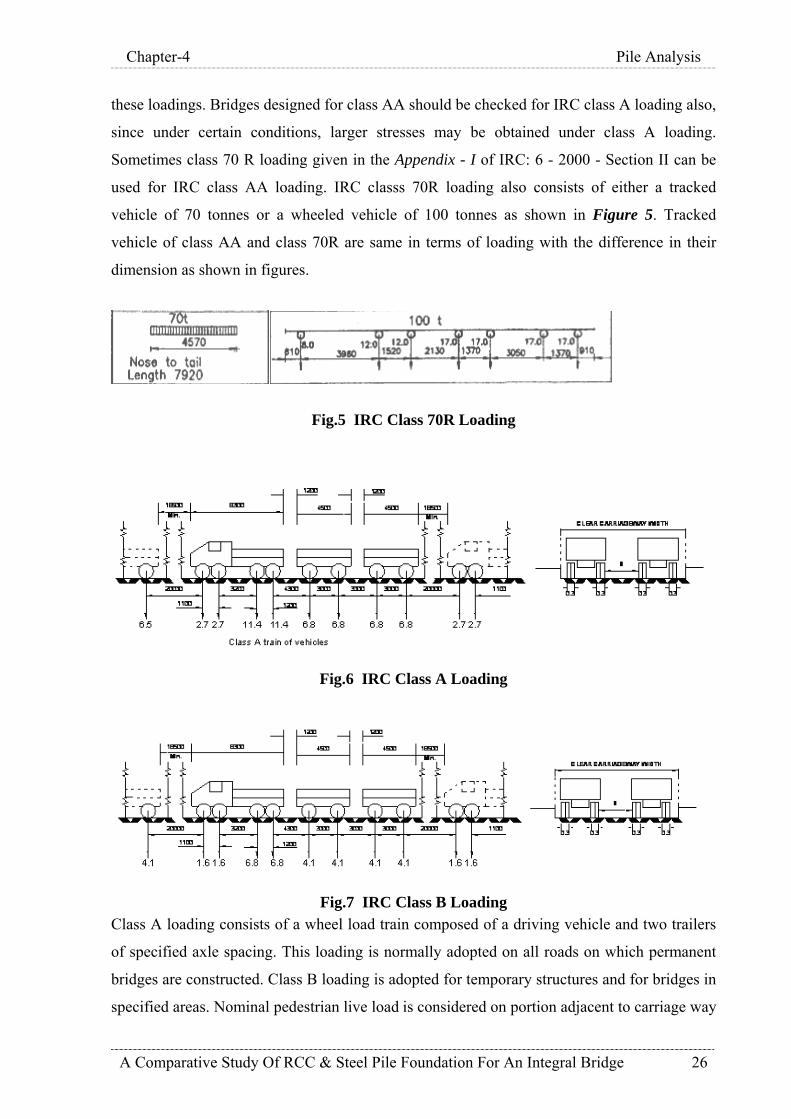
Sometimes class 70 R loading given in the Appendix - I of IRC: 6 - 2000 - Section II can be
used for IRC class AA loading. IRC classs 70R loading also consists of either a tracked
vehicle of 70 tonnes or a wheeled vehicle of 100 tonnes as shown in Figure 5. Tracked
vehicle of class AA and class 70R are same in terms of loading with the difference in their
dimension as shown in figures.
Fig.5 IRC Class 70R Loading
Fig.6 IRC Class A Loading
Fig.7 IRC Class B Loading
Class A loading consists of a wheel load train composed of a driving vehicle and two trailers
of specified axle spacing. This loading is normally adopted on all roads on which permanent
bridges are constructed. Class B loading is adopted for temporary structures and for bridges in
specified areas. Nominal pedestrian live load is considered on portion adjacent to carriage way

Chapter-4 Pile Analysis
A Comparative Study Of RCC & Steel Pile Foundation For An Integral Bridge 27
and conveyor area. Live load due to operation of conveyor which includes belt pull, material
live load, belt and idler weight is also considered.
4. Impact Load On Moving Live Load: The dynamic force induced by vehicle-bridge interaction resulting from the passage of
vehicles plays a significant role in bridge design. In practice to allow for such a dynamic
effect, it is required that static vehicle force be increased by a dynamic allowance factor,
called the impact factor in design. However, it has been observed that dynamic vehicle load on
bridge depends on dynamic properties of vehicle, dynamic properties of bridge, vehicle speed
and bridge surface roughness. This dynamic force is an important parameter in bridge design
and evaluation. In addition to the importance in design, dynamic vehicle load causes subtle
problems and contributes to fatigue, surface wear and cracking of concrete that leads to
corrosion. It continually degrades bridges and increases the necessity of regular maintenance.
The need to develop an approach and derive a simple closed form solution to predict the
dynamic vehicle load for applications of bridge design is apparent. More detailed analysis is
required to reach such a closed form solution which is out of scope of this study. While the
actual modeling of this effect can be a complex affair, the impact factor used by IRC allows
for a conservative solution of the problem.
As per Cl. 211 of IRC:6-2000, impact factor for standard vehicles is given as under:
For class A & B loading: a). Impact factor for RCC bridges = 4.5/(6+L)
b). Impact factor for steel bridges = 9/(13.5+L), where L is span in meters.
For class AA & 70R loading: a). For spans less than 9 m:
i). For tracked vehicles- 25% for spans upto 5m linearly reducing to 10% for spans of
9m
ii). For wheeled vehicles- 25%
b). For spans of 9 m or more:
i). RCC bridges-
For tracked vehicles- 10% for spans up to 40 m and in accordance with the curve
given in figure 5 for span in excess of 40 m.
For wheeled vehicles- 25% for spans up to 12 m and in accordance with the curve
given in figure 5 for span in excess of 12 m.
ii). Steel bridges-
For tracked vehicles- 10% for all spans
Chapter-4 Pile Analysis
A Comparative Study Of RCC & Steel Pile Foundation For An Integral Bridge 28
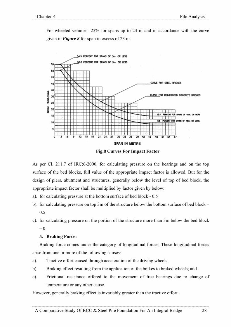
For wheeled vehicles- 25% for spans up to 23 m and in accordance with the curve
given in Figure 8 for span in excess of 23 m.
Fig.8 Curves For Impact Factor
As per Cl. 211.7 of IRC:6-2000, for calculating pressure on the bearings and on the top
surface of the bed blocks, full value of the appropriate impact factor is allowed. But for the
design of piers, abutment and structures, generally below the level of top of bed block, the
appropriate impact factor shall be multiplied by factor given by below:
a). for calculating pressure at the bottom surface of bed block - 0.5
b). for calculating pressure on top 3m of the structure below the bottom surface of bed block –
0.5
c). for calculating pressure on the portion of the structure more than 3m below the bed block
– 0
5. Braking Force:
Braking force comes under the category of longitudinal forces. These longitudinal forces
arise from one or more of the following causes:
a). Tractive effort caused through acceleration of the driving wheels;
b). Braking effect resulting from the application of the brakes to braked wheels; and
c). Frictional resistance offered to the movement of free bearings due to change of
temperature or any other cause.
However, generally braking effect is invariably greater than the tractive effort.
Chapter-4 Pile Analysis
A Comparative Study Of RCC & Steel Pile Foundation For An Integral Bridge 29
As per IRC, the braking effect on a simply supported span or a continuous span or any other
type of bridge unit shall be assumed to have the following value:
a). In case of single lane or a two lane bridge: 20% of the first train load plus 10% of load
of succeeding train or part thereof, the train load in one lane only being considered at a time.
Where the first train is not entirely covering the full span, the braking force shall be taken as
equal to 20% of the loads actually on the span.
b). In case of bridge having more than two lanes: as in a). above for the first two lanes
plus 5% of the loads on the lanes in excess of two.
This braking force is assumed to act at a height of 1.2 m above the roadway surface.
The distribution of longitudinal horizontal forces among bridge supports is affected by
horizontal deformation of bridges, flexing of supports and rotation of foundations. IRC:6
gives procedure for the distribution of horizontal forces for spans resting on stiff and flexible
supports. As present case is of flexible supports, only later case is presented here.
In simple and continuous decks with flexible supports, distribution of horizontal forces can
estimated after taking into account of deformation of bearings, flexing of piers and abutment
and rotation of foundation as well as location of Zero Movement Point (Z.M.P.) of the deck.
Shear rating of a support is the horizontal force required to move the top of the support
through a unit distance taking into account horizontal deformation of the bridge, flexibility of
the support and rotation of the foundation. The distribution of the horizontal forces depends
solely on shear ratings of the supports and may be estimated in proportion of shear rating of
individual support to the sum of shear ratings of all the supports.
But here in this study, braking force to be distributed to each support is calculated as total
braking forces divided by number of supports because there are other horizontal forces which
are large in magnitude (wave, wind, current, earthquake etc.) which are governing the
design. So distribution of the braking force like above mentioned method gives quite
satisfactory results.
6. Wind Load:
Wind load on a bridge may act –
- Horizontally, transverse to the direction of span.
- Horizontally, along the direction of span,
- Vertically upwards, causing uplifts.
- Wind load on vehicles.

Chapter-4 Pile Analysis
A Comparative Study Of RCC & Steel Pile Foundation For An Integral Bridge 30
Wind load may not generally significant in short span bridges. For medium span bridges,
the design of substructure is affected by wind loading. The super structure design is affected
by wind only in case of long span bridges. The bridge covered in this study project is not of
long span but still effect of wind force on the structure is analyzed for because it is situated
into the sea and flexibility and slenderness of the piles. Wind force is calculated in accordance
with IS:875 part 3 -1987. A brief description of wind load is presented here.
Wind means motion of air in atmosphere. The response of structure to wind depends upon
characteristics of wind. From point of view of assessing wind load, it is convenient to divide
the wind into two categories: rotating and non rotating. Rotating winds are caused by tropical
cyclones and tornadoes. The wind speed caused by this may exceed 200 km/h. Non
rotating winds are caused by differential pressures and thus move in the preferred direction.
These are also called pressure system wind. Their speed can also exceed 200 km/h.
A large number of structures those are being constructed at present tend to be wind
sensitive because of their shapes, slenderness, flexibility, size and lightness. Tall and slender
structures are flexible and exhibit a dynamic response to wind. Tall structure vibrate in the
wind due to turbulence inherent in the wind as well as that generated by the structure itself due
to separation of the flow. Thus there is a mean and fluctuating response to the wind. Besides
this dynamic forces act not only in the direction of the wind flow but also in a direction
perpendicular to it so that tall structures exhibit across wind response also.
Along wind response has a mean component and fluctuating component. The latter is
further expressed as a sum of background and resonant components. If the damping is small,
which is usually the case, the bulk of the contribution is due to the resonant portion. Across
wind response is on account of flow separation from cross section of the structure which
results in vortices being shed at a given frequency. The pattern of this across wind
phenomenon is comparatively more regular for circular sections such as those for chimneys
and towers which can undergo resonant vibrations when the structural frequency matches with
the forcing frequency. The response is affected significantly by the turbulence content of the
wind.
A theoretical treatment of tall slender structures in the along wind direction is better
developed than for across wind direction and for this reason it may be advisable to undertake
model studies in a wind tunnel for such structures.
Clause 7.1 of IS:875 (part 3)-1987 contains methods of evaluating the dynamic effects of
wind on flexible structures that can oscillate in wind. The wind on earth’s surface is turbulent
in nature that gives rise to randomly varying wind pressures about a certain value associated

Chapter-4 Pile Analysis
A Comparative Study Of RCC & Steel Pile Foundation For An Integral Bridge 31
with the mean wind speed. The dynamic part of the wind pressure would set up oscillations in
a flexible structure which may be defined as one having the fundamental time period of
vibration more than 1 second. Oscillations will thus be caused in the along wind direction.
Flexible structures also respond to across wind direction on account of vortex shedding. In
the cross wind direction, a flexible structure would tend to oscillate due to shedding of eddies
alternately from either side of the structure at regular intervals, thus imposing a dynamic force
that has a major component in a direction normal to that of wind(lift) and only a small
component along the wind(drag). The frequency of eddy shedding is dependent on structural
size, shape and wind speed, all grouped into a non dimensional parameter called Strouhal
Number. The present code does not lay down any specific procedure for determining the
design wind force related to the cross wind motion.
Code gives for procedure for only determining along wind force using Gust Factor
method. This method uses hourly mean wind speed concept instead of 3 second gust wind
speed as in static method of calculating wind pressures. The static wind pressure thus obtained
is then multiplied by Gust factor G. The structure is considered to vibrate in its fundamental
mode of vibration. The gust factor G includes the effect of non correlation of the peak
pressures by defining a size reduction factor S. It also accounts for the resonant and the non-
resonant effects of the random wind pressures. The equation for G contains two terms one for
the low frequency wind speed variations called the non resonant or background effects and
other for resonance effects. The first term accounts for the natural frequency of vibration of
the structure while the second term depends on the gust energy and aerodynamic admittance at
the natural frequency of vibration as well as on damping of the system. The resonant response
is insignificant for rigid structures (T>1.0 sec). For flexible structures, the background factor
B may be small resulting in reduced wind forces obtained from dynamic analysis as compared
to static analysis. The roughness factor r together with the peak factor gf is a measure of the
turbulence intensity present in the wind. Thus gf.r is equivalent to twice the turbulence
intensity.
The integral piled approach which is covered in this study is a flexible structure having
natural time period of more than 1.0 second. So wind force is applied to the exposed face of
the elements (pile, beams and slab) of the structure as per Gust factor method described in
IS:875(part 3)-1987 using force coefficient in both lateral directions (positive and negative).
In addition to this, wind load on moving vehicles over bridge as per Cl.212.4 of IRC:6-2000.
This clause states that the lateral wind force against any exposed moving live load shall be

Chapter-4 Pile Analysis
A Comparative Study Of RCC & Steel Pile Foundation For An Integral Bridge 32
considered as acting at 1.5 m above the roadway and shall be assumed to have the following
values:
Highway bridges, ordinary - 300 kg/linear meter.
Highway bridges, carrying tramway - 450 kg/linear meter.
While calculating the wind force on live load, clear distance between the trailers of train
of vehicles shall not be omitted.
Wind load is applied both for operating case and extreme (storm wind) case. Wind speed
considered in each of these cases is obtained from site investigation report.
7. Seismic Force:
In general, structures subjected to earthquake forces are to be designed to survive the
strains resulting from the design earthquake motion. Factors that are considered when
designing to resist earthquake motions are:
1. The proximity of the site to known active faults.
2. The seismic response of the soil at the site.
3. The dynamic response characteristics of the total structure.
Bridge as a whole and every part of it shall be designed and constructed to resist stresses
produced by lateral forces produced due to earthquake. The stresses shall be calculated as the
effect of a force applied horizontally at the centre of mass of the elements of the structure into
which it is conveniently divided for the purpose of design. The forces shall be assumed to
come from any horizontal direction.
All components of the bridge, that is, superstructure, substructure, bearing, foundation and soil are susceptible to damage in the event of strong ground shaking. The earthquake resistant design should consider the effect of earthquake motions on each component of the bridge. The design should ensure that seismic resistance of the bridge and its components is adequate to meet the general requirement so that emergency communication after the earthquake shall be maintained with appropriate reliability for the design basis earthquake.
As per IRC:6-2000, all bridges in seismic zone V shall be designed for seismic forces.
Major bridges i.e. with total lengths of more than 60m in zones III and IV shall be designed
for seismic forces. Bridges in zones I and II need not be designed for seismic forces. The
vertical seismic coefficient shall be considered in case of structures built in zone IV and V in
which stability is criterion for design or for overall stability analysis of the structure.
Following are the assumptions given in the draft version of IS:1893-1984 “Criteria For
Earthquake Resistant Design Of Structures (Part 3) Bridges and Retaining Walls” for the
earthquake analysis of bridges:
Chapter-4 Pile Analysis
A Comparative Study Of RCC & Steel Pile Foundation For An Integral Bridge 33
a) The seismic forces due to design basis earthquake (DBE) should not be combined with
design wind forces,
b) The scour to be considered for design shall be based on mean design flood. In the absence
of detailed data the scour to be considered for design shall be 0.9 times the maximum design
scour depth,
c) The earthquake accelerations should be applied to full mass in case of submerged structures
and not on buoyant mass,
d) The seismic force on live load in bridges should not be considered in longitudinal direction.
The seismic force on live load should be considered in transverse direction as,
e) The seismic force on flowing mass of water in the longitudinal direction in case of
aqueducts should not be considered, however seismic force on this water mass be considered
in transverse direction. The hydrodynamic action of water on the walls of water carrying
trough be considered on liquid retaining structures,
f) The earthquake accelerations on embedded portion of bridges foundation should be reduced
as per provisions made in code ,
g) The value of elastic modulus of material, where required, may be taken as for static
analysis unless a more definite value is available for use in seismic condition.
As per IS:1893-1984 “Criteria For Earthquake Resistant Design Of Structures”,
seismic force due to live load shall be ignored while acting in the direction of traffic but shall
be taken into consideration while acting in the direction perpendicular to traffic. Seismic force
due to live load shall be calculated for 50% of the design live load excluding impact for
railway bridges and 25% of the design live load excluding impact for road bridges. For
calculating stresses due to live load during earthquake, 100% design live load for railway
bridges and 50% design live load for road bridge is considered. Horizontal as well as vertical
seismic coefficient shall be calculated based on specifications given in IS:1893-2002.
The super structure of the bridge shall have a minimum factor of safety of 1.5 against
overturning in the transverse direction due to simultaneous action of horizontal and vertical
accelerations.
The seismic forces on the sub structure above the normal scour depth shall be as
follows:
1). Horizontal and vertical forces due to dead, live and seismic loads transferred from
superstructure to the substructure through the bearings.
2). Horizontal and vertical seismic forces due to self-weight applied at the centre of mass
ignoring reduction due to buoyancy or uplift.

Chapter-4 Pile Analysis
A Comparative Study Of RCC & Steel Pile Foundation For An Integral Bridge 34
3). Hydrodynamic force acting on piers and modification in earth pressure due to
earthquake given in acting on abutments.
The hydrodynamic force on submerged portion of pier is also assumed to act in a horizontal
direction corresponding to that of earthquake motion. The total horizontal force is given by the
following formula:
F = Ce Ah We …………………4.1
Where,
Ce = a coefficient (see Table 1)
Ah = design horizontal seismic coefficient
We = weight of water in the enveloping cylinder.
Table1- Values Of Ce
Height Of Submerged Portion Of Pier (H) /
Radius Of Enveloping Cylinder Ce
1.0 0.390
2.0 0.575
3.0 0.675
4.0 0.730
Some typical cases of submerged portion of piers and enveloping cylinders are illustrated in
following Figure 9.
Figure.9 Enveloping Cylinders
A typical diagram showing distribution of hydrodynamic pressure is shown in the Figure 10
below. Values of coefficients C1,C2,C3 and C4 for use in figure are shown in Table 2.

Chapter-4 Pile Analysis
A Comparative Study Of RCC & Steel Pile Foundation For An Integral Bridge 35
Figure.10 Pressure Distribution
Table2- Pressure Distribution Co-efficient
C1 C2 C3 C4
0.1 0.410 0.026 0.9345 0.2 0.673 0.093 0.8712 0.3 0.832 0184 0.8103 0.4 0.922 0.289 0.7515 0.5 0.970 0.403 0.6945 06 0.990 0.521 0.6390 0.8 0.999 0.760 0.5320 1.0 1.000 1.000 0.4286
When relative movement between two adjacent units of a bridge are designed to occur at a
separation/expansion joint, sufficient clearance shall be provided between them, to permit the
calculated relative movement under design earthquake conditions to freely occur without
inducing damage. Where the two units may be out of phase, the clearance to be provided may
be estimated as the square root of the sum of squares of the calculated displacements of the
two units under maximum elastic seismic forces.

Chapter-4 Pile Analysis
A Comparative Study Of RCC & Steel Pile Foundation For An Integral Bridge 36
8. Wave Force:
Wave force on vertical cylindrical pile is calculated in accordance with Coastal
Engineering Manual (Part 6)-2006. A brief description of the same is given here:
Morison et al. (1950) suggested that the horizontal force per unit length of a vertical
cylindrical pile subjected to waves is analogous to the mechanism by which fluid forces on
bodies occur in unidirectional flow, and this force can be expressed by the formulation,
uDuCdtduDCfff DMDi ρπρ
21
4
2
+=+= …………………4.2
Where,
fi = inertial force per unit length of pile;
fD = drag force per unit length of pile;
ρ = mass density of fluid;
D = pile diameter;
u = horizontal water particle velocity at the axis of the pile;
du/dt = horizontal water particle acceleration;
CD = drag hydrodynamic force coefficient;
CM = inertia or mass hydrodynamic coefficient;
Variables important in determining wave forces on circular pile subjected to wave motion are
shown in Figure.11 below.
Figure.11 Definition Sketch Of Wave Forces On A Vertical Cylinder.

Chapter-4 Pile Analysis
A Comparative Study Of RCC & Steel Pile Foundation For An Integral Bridge 37
The inertia force fi term is of the form obtained from an analysis of the force on a body
in an accelerated flow of an ideal non viscous fluid. The drag force term fD is the drag force
exerted on a cylinder in a steady flow of a real viscous fluid. Using linear wave theory,
MacCamy and Fuchs (1954) analyzed theoretically the problem of waves passing a circular
cylinder. Their analysis assumed an ideal non viscous fluid and led to an inertia force having
the form given for fi under special conditions. Although their theoretical result is valid for all
ratios of pile diameter to wavelength, D/L, the inertia force was found to be nearly
proportional to the acceleration du/dt for small values of D/L (where L is wavelength
calculated by linear theory). This theoretical result provides an indication of how small the
pile should be for above equation to apply, and the restriction is given as:
05.0<LD
Where L is calculated by linear wave theory. This restriction will seldom be violated for
slender pile force calculations; however, the restriction may be important when applying
above equation to larger structures such as cylindrical caissons.
For application of above equation, it is necessary to choose an appropriate wave theory
for estimating particle velocity and acceleration from values of wave height H, wave period T
and water depth d and for that particular wave condition, appropriate values of coefficient CD
& CM must be selected.
Calculation of forces and moments:
For structural design of a single vertical pile, it is often unnecessary to know in detail
the distribution of forces over the height of the pile. Instead, the designer needs to know the
total maximum force and the total maximum moment about the mud line (z = -d) acting on the
pile. The total time-varying force and the time-varying moment acting about the mud line is
found by integrating equation 4.2 between the bottom and the free surface, i.e.,
Di
n
dD
n
di FFdzfdzfF +=+= ∫∫
−−
…………………4.3
Di
n
dD
n
di MMdzfdzdzfdzM +=+++= ∫∫
−−
)()( …………………4.4
In general form these quantities may be written
iMi HKDgCF4
2πρ= …………………4.5

Chapter-4 Pile Analysis
A Comparative Study Of RCC & Steel Pile Foundation For An Integral Bridge 38
DDD KgDHCF 2
21 ρ=
…………………4.6
iiMi dSHKDgCM4
2πρ= …………………4.7
DDDD dSKgDHCM 2
21 ρ=
…………………4.8
in which CM and CD may be assumed as constant and factors Ki,KD,Si and SD are
dimensionless parameters that depends on the specific wave theory used in integrations.
Linear wave theory:
The force on a slender cylindrical pile can be estimated using linear wave theory, but
the result is limited to situations where linear wave theory provides a reasonable
approximation of the wave kinematics. This implies small amplitude waves and greater
depths.
With the pile center line located at x = 0, as shown in Figure 8, the equations for surface
elevation, horizontal component of local fluid velocity and horizontal component of local fluid
acceleration are respectively,
⎥⎦⎤
⎢⎣⎡=
TtH πη 2cos
2 …………………4.9
[ ][ ] ⎥⎦
⎤⎢⎣⎡+
=T
tLd
LdzL
gTHu ππ
π 2cos/2cosh
/)(2cosh2
…………………4.10
Introducing above equations into basic equation of force gives following equations for inertia
and drag force.
[ ][ ] ⎥⎦
⎤⎢⎣⎡−⎥
⎦
⎤⎢⎣
⎡ +=
Tt
LdLdz
LHDgCf Mi
ππ
πππρ 2sin/2cosh
/)(2cosh4
2
…………………4.11
[ ][ ] ⎥⎦
⎤⎢⎣⎡
⎥⎦⎤
⎢⎣⎡
⎥⎥⎦
⎤
⎢⎢⎣
⎡⎥⎦
⎤⎢⎣
⎡ +=
Tt
Tt
LdLdz
LgTgDHCf DD
πππ
πρ 2cos2cos/2cosh
/)(2cosh42
12
2
22 …………………4.12
Above equations show that the two force components vary with elevation z on the pile and
with time t. The inertia force fi is maximum for sin (-2πt/T) = 1, which corresponds to t = -T/4
for linear wave theory. Thus, the maximum inertia force on the pile occurs T/4 seconds before
the passage of the wave crest that occurs at t = 0. The maximum value of the drag force
component fD coincides with passage of the wave crest at t = 0.

Chapter-4 Pile Analysis
A Comparative Study Of RCC & Steel Pile Foundation For An Integral Bridge 39
The magnitude of the maximum inertia force per unit length of pile varies with depth
the same as the horizontal acceleration component. The maximum value occurs at the swl (z =
0) and decreases with depth. The same trend is true for the maximum drag force per unit
length of pile except the decrease with depth is more rapid because the depth attenuation
factor (cosh[2π(z+d)/L}/cosh[2πd/L]) is squared in equation.
The total time-varying force and the time-varying moment acting about the mudline is found
for linear wave theory by integrating equations 4.11 & 4.12 between the bottom and the swl (z
= 0) using the expressions for fi and fD given by equations respectively. The integration results
in total force and moment components given by equations with values of the dimensionless
parameters Ki , KD , Si , and SD given by,
⎥⎦⎤
⎢⎣⎡−⎥⎦
⎤⎢⎣⎡=
Tt
LdKi
ππ 2sin2tanh21
…………………4.13
[ ] ⎥⎦⎤
⎢⎣⎡
⎥⎦⎤
⎢⎣⎡
⎥⎦
⎤⎢⎣
⎡+=
Tt
Tt
LdLdK D
πππ
π 2cos2cos/4sinh
/41tanh81
…………………4.14
⎥⎦⎤
⎢⎣⎡
⎥⎦⎤
⎢⎣⎡=
Tt
Ttn ππ 2cos2cos
41
[ ][ ]LdLd
LdSi /2sinh)/2(/2cosh11ππ
π−+= …………………4.15
[ ][ ]⎥⎦
⎤⎢⎣
⎡ −++=
LdLdLd
nSD /4sinh)/4(
/4cosh121
21
21
πππ …………………4.16
Where,
[ ]⎥⎦⎤
⎢⎣
⎡+==
LdLd
CC
n g
/4sinh/41
21
ππ
The maximum values for total inertia force and moment are found by taking t = -T/4 in
equations. Likewise, the maximum values for total drag force and moment are found by taking
t = 0 in equations. A conservative design approach would be to sum the individual maximum
inertia and drag components that occur during a wave cycle to get total maximum force and

Chapter-4 Pile Analysis
A Comparative Study Of RCC & Steel Pile Foundation For An Integral Bridge 40
moments. However, the individual maximums do not occur simultaneously, so the real
maximum total force and moment will be somewhat less. The correct method is to calculate
the time-varying sum of inertia and drag components, and then use the maximum sum that
occurs over the wave cycle. The time at which the maximum occurs may vary depending on
the selected values for CM and CD.
Although linear wave theory provides a nice closed-form solution for forces and
moments on slender cylindrical piles, in practice the hydrodynamics associated with the
steeper design wave conditions will not be well predicted by linear wave theory. Even more
critical is the fact that linear theory provides no estimate of the force caused by that portion of
the wave above the swl, an area where the horizontal velocities and accelerations are the
greatest. An adhoc adjustment is to assume a linear force distribution having a maximum
value of force estimated at the still-water line and a value of zero at the crest location of the
linear wave (H/2 above the swl). Most likely, the design wave will be nonlinear with steep
wave crests and with much of the wave height above the swl, and it would be well advised to
use an appropriate nonlinear wave theory in the force and moment calculation.
Non linear wave theory:
Design conditions for vertical cylindrical piles in coastal waters will most likely
consist of nonlinear waves characterized by steep crests and shallow troughs. For accurate
force and moment estimates, an appropriate nonlinear wave theory should be used to calculate
values of u and du/dt corresponding to the design wave height, wave period, and water depth.
The variation of fi and fD with time at any vertical location on the pile can be estimated using
values of u and du/dt from as Stoke's fifth-order wave theory (Skjelbriea et al. 1960) or
stream-function theory (Dean 1974).
The separate total maximum inertia force and moment and total drag force and
moment on a vertical cylindrical pile subjected to nonlinear waves can be estimated using
equations 4.7 to 4.10. Values for Ki , KD , Si , and SD in these equations are given by Kim ,
KDm , Sim, and SDm , respectively, in the nomograms shown in Figures A.1 through A.4 of
Appendix A. These nomograms were constructed using stream-function theory (Dean 1974),
and they provide the maximum total force and total moment for the inertia and drag
components considered separately rather than the combined total force and moment. The
curves in these figures represent wave height as a fraction of the breaking wave height.
Breaking wave height is obtained from Figure 12 for values of d /gT2 using the curve labeled
Breaking Limit. Same figure can also be used for selecting appropriate wave theory for design
wave.

Chapter-4 Pile Analysis
A Comparative Study Of RCC & Steel Pile Foundation For An Integral Bridge 41
For linear waves, the maximum inertia force occurs at t = -T/4 and the maximum drag
force occurs at t = 0. However, for nonlinear waves the times corresponding to maximum
inertia and drag forces are phase dependent and not separated by a constant quarter
wavelength as in linear wave theory.
The total maximum force Fm, where the sum of the inertia and drag components is maximum
can be estimated as,
DgHCF Dmm2ρφ= …………………4.17
Similarly maximum moment Mm can be estimated as,
DdgHCM Dmm2ρα=
…………………4.18
Values of Фm and αm are estimated from Figure A.5 to A.6 of Appendix A. These figures are
also constructed using stream function theory. Selection of figure depends upon non
dimensional parameter W given as,
HCDC
WD
M= …………………4.19

Chapter-4 Pile Analysis
A Comparative Study Of RCC & Steel Pile Foundation For An Integral Bridge 42
Figure.12 Breaking Wave Height & Regions Of Validity Of Various Wave Theories.
Wave force is calculated and applied for both operating and extreme (storm) cases.
9. Water Current Force:
For structures those are located in a place where there are strong currents such as a tidal
currents or river flow, it is necessary to carry out investigations on the forces produced by the
currents with largest velocity from the most unfavorable direction. Depending upon the type
of the structures or members, it may also be necessary to consider vertical distribution of the
current velocity. When waves coexist with currents, it is necessary to use the current velocity
and direction in the state of coexistence. Type of currents in the sea area include ocean
currents, tidal currents and wind driven drift currents along with density currents caused by
density differences due to salinity or water temperature. In addition in the coastal area, there
are longshore currents and rip currents caused by waves.

Chapter-4 Pile Analysis
A Comparative Study Of RCC & Steel Pile Foundation For An Integral Bridge 43
Force due to water current is applied as per provisions given in IRC:6. As per Cl. 213 of
IRC:6-2000, any part of a bridge which may be submerged in running water shall be designed
to sustain safely the horizontal pressure due to the force of current. On piers parallel to the
direction of water current, the intensity of pressure shall be calculated from the following
equation:
P = 52KV2 …………………4.20
Where P = intensity of pressure in kg/m2;
V = velocity of the current at the point where pressure is being calculated;
K = a coefficient having following value for different shape of piers;
a). square ended pier = 1.5
b). circular pier = 0.66
c). piers with triangular cut and ease waters, the angle = 0.5
included between faces being 30 degrees or less
d). piers with triangular cut and ease waters, the angle = 0.5 to 0.7
included between faces being more than 30 degrees
but less than 60 degrees
e). piers with triangular cut and ease waters, the angle = 0.7 to 0.9
included between faces being more than 60 degrees
but less than 90 degrees
Current force is applied for operating and extreme cases. In operating case, mean sea level is
considered as top water level and in extreme condition HAT level is considered as top water
level.
10. Buoyancy:
Effect of buoyancy is considered in calculating the weight of portion of foundation under
water. Buoyancy effect is also considered in working out bearing capacity of pile foundation.
11. Thermal Effects:
There are two thermal effects which can induce stresses in bridges. The first is a uniform
temperature change which results in an axial expansion or contraction. If restrained, such as in
an arch or a frame bridge, this can generate significant axial force, bending moment and shear.
The second effect is that due to differential changes in temperature. If the top of a beam heats
up relative to the bottom, it tends to bend; if it is restrained from doing so, bending moment
and shear force are generated. Integral bridges undergo repeated expansions and contractions
due to daily or seasonal temperature fluctuations. For analysis, coefficient of thermal
expansion is taken as 11.7x10⁻⁶ /degree centigrade for reinforced concrete and steel.

Chapter-4 Pile Analysis
A Comparative Study Of RCC & Steel Pile Foundation For An Integral Bridge 44
12. Shrinkage And Creep:
These two effects need to be considered together they are interrelated. As concrete ages it
shrinks slightly. The rate at which the concrete shrinks decreases approximately exponentially
with time, with half of the total shrinkage normally occurring in the first one month and
remaining 75% in six months from commencement of drying. Creep in concrete is response to
long term stress; the concrete strain gradually increases to two or three times the elastic strain.
The creep strain rate decreases with time, similar to the way the shrinkage rate decreases.
2.1.1 Load Combinations:
Load combinations are considered as per IS 456:2006, IS 4651 (Part 4):1989 and IRC 6:2000.
Detailed load combinations are given in chapter of load calculations.
4.2 Load Calculation: 1. Dead Load :
Unit weight of concrete = 25 kN/m3
a). Self weight of pile = π x 1.0 x 1.0 x 25/4 = 19.635 kN/m
b). Self weight of pile muff
= ((2.4 x 2.4 x 0.35) + (((2.4 x 2.4) + (1.5 x 1.5) + (sqrt (1.5 x 1.5 x 2.4 x 2.4))) x 0.35/3) – (π
x 1.0 x 1.0 x 0.7)) x 25 = 70.52 kN

Chapter-4 Pile Analysis
A Comparative Study Of RCC & Steel Pile Foundation For An Integral Bridge 45
c). Self weight of precast pile cap
= ((((0.2 + 0.275) x 0.2/2) + (0.4 x 0.9) + ((0.125 + 0.1) x 0.6/2))x2) x 25 = 23.75 kN/m
d). Self weight of precast longitudinal girders
L-girder-1 & 8
= ((0.4 x 0.725) + ((0.2 + 0.15) x 0.25/2) + ((0.2 + 0.15) x 0.6 / 2)) x 25 = 10.97 kN/m
L-girder-2 to 5
= ((0.4 x 0.725) + ((0.2 + 0.15) x 0.25)) x 25 = 9.44 kN/m

Chapter-4 Pile Analysis
A Comparative Study Of RCC & Steel Pile Foundation For An Integral Bridge 46
L-girder-6 & 7
= ((0.4 x 0.725) + ((0.2 + 0.15) x 0.25/2) + ((0.2 + 0.15) x 0.45/2)) x 25 = 10.34 kN
/m
e). Self weight of insitu concrete over pilecap
= ((16.4 x 2 x 1.005 x 25) – (10.97 + (4 x 9.44) + (2 x 10.34))) / 16.4 = 46.01 kN
/m
f). Self weight of insitu concrete over pile muff
= (2.4 x 1.5 x 0.9 x 25) – (23.75 x 1.5) = 45.375 kN
g). Self weight of cross diaphragm
= 0.8 x 1.005 x 25 = 20.1 kN
h). Self weight of deck slab (precast+insitu)
= 0.35 x 25 = 7 kN /m2
i). Self weight of wearing course
Chapter-4 Pile Analysis
A Comparative Study Of RCC & Steel Pile Foundation For An Integral Bridge 47
= 0.112 x 22 = 2.464 kN /m2
j). Self weight of kerb = 0.25 x 0.25 x 25 = 1.5625 KN/m
k). Dead load due to handrail (approx.) = 1 kN/m
l). Dead load due to light pole
On left side of carriage way = 10 kN
On right side of carriage way = 15 kN
j). Dead load due to pipelines
Considering 2 steel pipes of 600mm diameter and 15 mm each.
Weight of pipe = π x (0.632-0.62) x 78.5 x 2 = 4.56 kN/m
Weight of water in pipe = π x 0.62 x 78.5 x 2 = 5.82 kN/m
Total weight including 10% of wt. for pipe staging = 11.41 kN/m
k). Dead load from conveyor pedestal = 15 kN
2. Construction, Erection and Handling Loads:
Following value of load is considered as construction live load in design of precast elements.
Precast pile cap beam = 20 kN
Precast longitudinal girder = 20 kN
Precast deck plank = 2 kN/m2
An impact factor of 1.25 is considered for checking design of precast members for handling.
3. Live Load:
3.1 Vehicular Live Load:
Width of carriageway = 7.5 m
As per Cl. 207.4 of IRC:6-2000, 2 lanes are considered for design purpose.
Following combination of vehicles are considered.
1. One lane of IRC Class 70R tracked vehicle.
2. One lane of IRC Class 70R wheeled vehicle.
3. Two lane of IRC class A.
4. In addition to above stated IRC specified live loads, a 100 T crane is also considered in
analysis and design is considered as per user requirement. Configuration of 100T crane
is same as that of IRC Class AA tracked with the difference is only that in 100T crane,
total load will be 100 T instead of 70T as in case of Class AA tracked vehicle.
3.2 Conveyor Live Load:
Live load due to operation of the conveyor system is taken as 1.8 kN in longitudinal direction
as received from material handling department.

Chapter-4 Pile Analysis
A Comparative Study Of RCC & Steel Pile Foundation For An Integral Bridge 48
In addition to above mentioned live loads, live load of 150 kg/m2 is considered on the deck
portion except at carriageway and at conveyor pedestals.
4. Impact Load Of Moving Live Load:
Impact factor are calculated as per Cl. 211 of IRC:6-2000.
IRC Class 70R tracked vehicle = 10 %
IRC Class 70R wheeled vehicle = 25 %
IRC Class A vehicle = 25 %
100 T crane = 10%
Impact factor is considered only for design of super structure elements not for design of piles.
5. Braking Force:
Braking force is calculated as per Cl. 214.2 of IRC:6-2000.
IRC Class 70R tracked vehicle:
Nos. of trains of vehicles per unit of bridge = 5
Braking force per support = ((700x20%) + (4x700x10%)) / 28 = 15 kN
IRC Class 70R wheeled vehicle:
Nos. of trains of vehicles per unit of bridge = 4
Braking force per support = ((1000x20%) + (3x1000x10%)) / 28 = 17.85 kN
IRC Class A vehicle:
Nos. of trains of vehicles per unit of bridge = 4
Braking force per support = ((554x20%) + (3x554x10%)) / 28 = 9.892 kN
100 T crane:
Nos. of trains of vehicles per unit of bridge = 2
Braking force per support = ((1000x20%) + (1000x10%)) / 28 = 10.71 kN
6. Wind Load:
Wind load is calculated as per Gust Factor method as per Cl. 8 of IS:875 (part3)-1987.
6.1. Operating Condition:
Basic wind speed - 19 m/s
Height of structure above mean sea level - 10 m
Terrain category - 1
Class of structure - C
Probability factor k1 = 1 …………Table1 of IS:875 (part3)-1987
Terrain factor k2, = 0.78 ..………Table33 of IS:875(part3)-1987
Topography factor k3, = 1 ………Cl.5.3.3.1 of IS:875(part3)-1987
Design wind speed, Vz = Vbx k1x k2x k3,

Chapter-4 Pile Analysis
A Comparative Study Of RCC & Steel Pile Foundation For An Integral Bridge 49
Vz = 14.82m/s ……… Cl.8.2.1 of IS:875 (part3)-1987
Wind Pressure Pz = 0.6 V2z, …………Cl.8.3 of IS:875 (part3)-1987
Pz = 131.78 N/m2
Along wind load on the structure,
Fz = Cf Ae Pz G …………Cl.8.3 of IS:875 (part3)-1987
Where,
Cf = force coefficient,
Ae = effective frontal area considered for the structure,
Pz = design wind pressure,
G = gust factor and is given by,
( ) ⎥⎦
⎤⎢⎣
⎡+++=
βφ SEBrgG f
211
Where,
gf = peak factor defined as the ration of the expected peak
value to the root mean value of a fluctuating wind,
r = roughness factor which is dependent on the size of the
structure in relation to the ground roughness,
B = background factor indicating measure of slowly varying
component of fluctuating wind load,
SE/β = a measure of the resonant component of the fluctuating wind
Load.
Now for category 1 and height of 14m,
gf.r = 1.0 ……………Figure 8 of IS:875 (part3)-1987
L(h) = 1000 ……………Figure 8 of IS:875 (part3)-1987
Cy = 10
Cz = 12
Cz h / L(h) = 0.17
Width of structure b = 160 m
λ = Cyb/Cyh = 9.52
Background factor B = 0.6 ……………Figure 9 of IS:875 (part3)-1987
Natural frequency f0 = 0.67 Hz
Vh = 14.82 m/s
Reduced natural frequency F0 = Cz f0 h / Vh = 7.64

Chapter-4 Pile Analysis
A Comparative Study Of RCC & Steel Pile Foundation For An Integral Bridge 50
Size reduction factor S = 0.012
f0 L(h) / Vh = 45.47
gust energy factor E = 0.041
Gust factor G = 1.8
Wind load in transverse direction:
Wind load on pile:
Length of member l = 14.0 m
Width of the member b = 1.0 m
l/b = 14.0 m
Force coefficient Cf = 0.8 …………Figure 5 of IS:875 (part3)-1987
(for member of infinite length)
Reduction factor k = 0.845 …………Table25 of IS:875 (part3)-1987
Force coefficient = 0.675
(for considering reduction factor k)
Wind load F = Cf Ae Pz G
Where Cf = force coefficient,
Ae = effective area of the object normal to the wind direction,
Pz = design wind pressure,
G = gust factor,
Wind load on pile = 160.168N/m
Wind load on exposed face of cross beam:
Height of beam = 0.9 m
Width of beam = 0.8 m
Exposed area Ae = 0.72 m2
Force coefficient = 1
Wind load on cross beam = 170.845N
Wind load on front longitudinal beam:
Height of beam = 0.725 m
Exposed area Ae = 0.725m2/m
Force coefficient = 1
Wind load on cross beam = 172N
Wind load on front exposed face of slab:
Height of beam = 0.280 m
Exposed area Ae = 0.280 m2/m

Chapter-4 Pile Analysis
A Comparative Study Of RCC & Steel Pile Foundation For An Integral Bridge 51
Force coefficient = 1
Wind load on cross beam = 66N
Wind load on vehicle:
Wind force on moving vehilce = 3.0 kN /m
Length = 160 m
Nos. of piles = 28
Wind load per pile = 18 kN
Wind load on conveyor pedestal:
Wind load on conveyor pedestal = 0.335 kN
Wind load in longitudinal direction:
Wind load on pile:
Wind load on pile = 160.168N/m
Wind load on exposed face of cross beam:
Height of beam = 0.9 m
Exposed area Ae = 0.9 m2/m
Force coefficient = 1
Wind load on cross beam = 214N
6.2. Extreme Condition:
Basic wind speed - 44 m/s
Height of structure above mean sea level - 4.5 m
Terrain category - 1
Class of structure - C
Probability factor k1 = 1 ………… Table1 of IS:875 (part3)-1987
Terrain factor k2, = 0.78 ………… Table33 of IS:875 (part3)-1987
Topography factor k3, = 1 ………… Cl.5.3.3.1 of IS:875 (part3)-1987
Design wind speed, Vz = Vbx k1x k2x k3,
Vz = 34.32 m/s ………… Cl.8.2.1 of IS:875 (part3)-1987
Wind Pressure Pz = 0.6 V2z, ………… Cl.8.3 of IS:875 (part3)-1987
Pz = 706.71 N/m2
Now for category 1 and height of 14m,
gf.r = 1.0 ………… Figure 8 of IS:875 (part3)-1987
L(h) = 1000 ………… Figure 8 of IS:875 (part3)-1987
Cy = 10
Cz = 12

Chapter-4 Pile Analysis
A Comparative Study Of RCC & Steel Pile Foundation For An Integral Bridge 52
Cz h / L(h) = 0.17
Width of structure b = 160 m
λ = Cyb/Cyh = 9.52
Background factor B = 0.6 ………… Figure 9 of IS:875 (part3)-1987
Natural frequency f0 = 0.67 Hz
Vh = 14.82 m/s
Reduced natural frequency F0 = Cz f0 h / Vh = 3.29
Size reduction factor S= 0.05
f0 L(h) / Vh = 19.63
gust energy factor E = 0.075
Gust factor G = 1.91
Wind load on pile:
Length of member l = 14.0 m
Width of the member b= 1.0 m
l/b = 14.0 m
Force coefficient Cf = 0.8 ………… Figure 5 of IS:875 (part3)-1987
(for member of infinite length)
Reduction factor k = 0.845 ………… Table25 of IS:875 (part3)-1987
Force coefficient = 0.675
(for considering reduction factor k)
Wind load F = Cf Ae Pz G
Where Cf = force coefficient,
Ae = effective area of the object normal to the wind direction,
Pz = design wind pressure,
G = gust factor,
Wind load on pile = 912.77N/m
Wind load on exposed face of cross beam:
Height of beam = 0.9 m
Width of beam = 0.8 m
Exposed area Ae = 0.72 m2
Force coefficient = 1
Wind load on cross beam = 973.629N
Wind load on front longitudinal beam:
Height of beam = 0.725 m
Chapter-4 Pile Analysis
A Comparative Study Of RCC & Steel Pile Foundation For An Integral Bridge 53
Exposed area Ae = 0.725 m2/m
Force coefficient = 1
Wind load on cross beam = 978.75N
Wind load on front exposed face of slab:
Height of beam = 0.280 m
Exposed area Ae = 0.280 m2/m
Force coefficient = 1
Wind load on cross beam = 378 N
Wind load on conveyor pedestal:
Wind load on conveyor pedestal = 1.8 kN
Wind load in longitudinal direction:
Wind load on pile:
Wind load on pile = 912.77N/m
Wind load on exposed face of cross beam:
Height of beam = 0.9 m
Exposed area Ae = 0.9 m2/m
Force coefficient = 1
Wind load on cross beam = 1215 N
7. Earthquake Force:
7.1 Transverse and longitudinal seismic force:
Seismic force is applied on full dead load and 50% of live load including conveyor live load.
Seismic force is calculated as per Cl.6.4.2 of IS:1893-2002.
The design horizontal seismic co-efficient is given by,
Ah = Z I (Sa/g) / 2R
Zone factor ‘z’ = 0.16
Importance factor ‘I’ = 1.5
Response reduction factor ‘R’ = 3
Time period ‘T’ (from staad) = 1.59 sec
Damping percentage = 5 %
Damping factor = 1.00
Sa/g = 0.855
Ah = 0.034
As per analysis in staad, time period is almost same in both direction. So, same design
horizontal seismic coefficient is applied in both directions.

Chapter-4 Pile Analysis
A Comparative Study Of RCC & Steel Pile Foundation For An Integral Bridge 54
7.2 Hydrodynamic force due to seismic action:
Horizontal force F = Ce Ah We
Diameter of pile = 1.0 m
Marine growth = 50 mm
Radius of enveloping cylinder ‘R’ = 0.55 m
Height of submerged portion of pile ‘H’= 5.1-1.15 = 1.95 m
H/R = 3.54
Ce = 0.704
Weight of enveloping cylinder ‘We’ = 18.99 kN
Total horizontal force ‘F’ = 0.454 kN
For C1 = 1 & C4 = 0.4286
CG of this horizontal force above bed level = C4H = 0.835 m
7.3 Seismic force on vehicle in transverse direction:
Total vehicular live load on a unit of approach = 2000 kN
(two train of 100T vehicle)
Nos. of supports over which load is to be distributed = 28
Seismic co-efficient = 0.034
Seismic force = 0.034 x 2000 x 0.5 / 28 = 1.21 kN
8. Wave Force:
8.1. Operating Condition (longitudinal & transverse direction):
Operating wave is considered in transverse as well as longitudinal direction consecutively in
the analysis.
Input:
Wave height (H) = 2.2 m
Time period (T) = 6.0 sec
Bed level = (+)3.15 CD
Still water level = (+)5.10 CD
Direction of wave = 180-270N
Density of sea water (γ) = 10.25 kN /m3
Diameter of pile (D) = 1.0 m
Marine growth = 50 mm
Deep water wave length (Lo) = gT2/2π = 56.21 m
Still water depth (d) = 5.1 – 3.15 = 1.95 m
Dimensionless water depth = d/gT2 = 0.01

Chapter-4 Pile Analysis
A Comparative Study Of RCC & Steel Pile Foundation For An Integral Bridge 55
Wave length (L) = ⎥⎦
⎤⎢⎣
⎡2
24tanhgT
Loπ = 26.04 m
Max. horizontal wave velocity (Umax) = HgT/2L = 2.49 m/s
Viscosity (ν) = 9.29X10⁻⁷m2/s
Reynold’s number (Re) = Umax D/v = 2.94X10⁶
Drag coefficient (CD) = 0.7
Inertia coefficient (CM) = 1.5
Relative wave height = H/d = 1.13
> 0.78
Hence it is a breaking wave.
Non dimensional parameter (W) = CM D/ CD H = 1.07
> 1.0
Dimensionless wave steepness = Hb/gT2 = 0.0075.
Breaking wave height (Hb) = 2.649 m
Ratio H/Hb = 0.831
Kim = 0.4
KDm = 0.6
Sim = 0.8
SDm = 0.9
Maximum inertial force on pile,
Fim = CM x γ x g x π x D x H x Kim / 4 = 11.72 kN
Maximum drag force on pile,
FDm = CD x γ x D x H2 x KDm / 2 = 10.94 kN
Total force F = Fim + FDm = 22.65 kN
Maximum moment due to inertial force
Mim = Fim x d x Sim = 18.28 kN.m
Maximum moment due to drag force
MDm = FDm x d x SDm = 19.20 kN.m
Total moment M = Mim + MDm = 37.47 kN.m
C.G. of this force about bed level = M/F = 1.65 m
8.2. Extreme Condition(at angle of 210 deg.):
Input:
Wave height (H) = 6.5 m

Chapter-4 Pile Analysis
A Comparative Study Of RCC & Steel Pile Foundation For An Integral Bridge 56
Time period (T) = 10.0 sec
Bed level = (+)3.15 CD
Still water level = (+)10.5 CD
Direction of wave = 210 N
Density of sea water (γ) = 10.25 kN /m3
Diameter of pile (D) = 1.0 m
Marine growth = 50 mm
Deep water wave length (Lo) = gT2/2π = 156.1 m
Still water depth (d) = 10.5 – 3.15 = 7.35 m
Dimensionless water depth = d/gT2 = 0.01
Wave length (L) = ⎥⎦
⎤⎢⎣
⎡2
24tanhgT
Loπ = 83.71 m
Max. horizontal water particle velocity (Umax) = HgT/2L = 3.81 m/s
Viscosity (ν) = 9.29X10⁻⁷m2/s
Reynold’s number (Re) = Umax D/v = 4.51X10⁶
Drag coefficient (CD) = 0.7
Inertia coefficient (CM) = 1.5
Relative wave height = H/d = 0.88
> 0.78
Hence it is a breaking wave.
Non dimensional parameter (W) = CM D/ CD H = 0.36
< 1.0
Dimensionless wave steepness = H/gT2 = 0.007.
Φm = 0.31
αm = 0.34
Maximum force on pile,
Fm = Φm x CD x γ x H2 x D = 106.9 kN
Transverse component of the force = 92.62 KN
Longitudinal component of the force = 53.47 KN
Maximum moment on pile,
Mm = αm x CD x γ x H2 x D x d = 833.3 kN.m
C.G. of this force about bed level = M/F = 7.79 m

Chapter-4 Pile Analysis
A Comparative Study Of RCC & Steel Pile Foundation For An Integral Bridge 57
Figure.13 Application Of Wave Force – Operating & Extreme
9. Current Force:
9.1. Operating Condition:
Input:
Bed level = (+)3.15 m
Scour level = (+)1.15 m
Still water level = (+)5.1 m
Diameter of pile = 1.0 m
Marine growth = 50.0 mm
Velocity at surface = 3.85 m/s
Velocity at mid depth = 2.25 m/s
Velocity at scour level = 1.80 ms
Direction of current = 1740N
Pressure due to current P = 0.52KV2 KN/m2
Where K = 0.66 for circular pile,
The current force on pile
At surface = 0.52 x 0.66 x 3.852 x (1.0+(2x0.05) = 5.6 kN /m
At mid depth = 0.52 x 0.66 x 2.252 x (1.0+(2x0.05) = 1.91 kN /m
At surface = 0.52 x 0.66 x 1.802 x (1.0+(2x0.05) = 1.22 kN /m

Chapter-4 Pile Analysis
A Comparative Study Of RCC & Steel Pile Foundation For An Integral Bridge 58
Figure.14 Application Of Current Force – Operating
9.2. Extreme Condition:
Input:
Bed level = (+)3.15 m
Scour level = (+)1.15 m
Still water level = (+)10.5 m
Diameter of pile = 1.0 m
Marine growth = 50.0 mm
Velocity at surface = 3.85 m/s
Velocity at mid depth = 2.25 m/s
Velocity at scour level = 1.80 ms
Direction of current = 1740N
Pressure due to current P = 0.52KV2 KN/m2
Where K = 0.66 for circular pile,
The current force on pile
At surface = 0.52 x 0.66 x 3.852 x (1.0+(2x0.05) = 5.6 kN /m
At mid depth = 0.52 x 0.66 x 2.252 x (1.0+(2x0.05) = 1.91 kN /m
At surface = 0.52 x 0.66 x 1.802 x (1.0+(2x0.05) = 1.22 kN /m

Chapter-4 Pile Analysis
A Comparative Study Of RCC & Steel Pile Foundation For An Integral Bridge 59
Figure.15 Application Of Current Force – Extreme
10. Thermal Effects:
Temperature difference of ±100 for axial elongation and contraction is applied to the pilecap
beams, longitudinal beams and slab elements.
11. Shrinkage Effect:
Permissible shrinkage strain in concrete ε = 0.0003
Coefficient of thermal expansion α = 11.7x10⁻⁶/0C
Temperature difference for above stated strain δT = ε / α
= 25.64 0C
12. Detailed Load Combinations: Detailed load combinations considered in the analysis are as follows:
DE
AD
LIV
E
WIN
D (+
X) E
XT
RE
ME
WIN
D (-
X) E
XT
RE
ME
WIN
D (+
Z) E
XT
RE
ME
WIN
D (+
X) O
PER
AT
ING
WIN
D (-
X) O
PER
AT
ING
WIN
D (+
Z) O
PER
AT
ING
CU
RR
EN
T (X
) EX
TR
EM
E
CU
RR
EN
T (X
) O
PER
AT
ING
WA
VE
EX
TE
ME
WA
VE
(+X
) OPE
RA
TIN
G
WA
VE
(+Z
) OPE
RA
TIN
G
TE
MPE
RA
TU
RE
( R
ISE
)
TE
MPE
RA
TU
RE
(FA
LL
)
SHR
INK
AG
E
SEIS
MIC
(X)
SEIS
MIC
(Z)
BR
EA
KIN
G
VE
HIC
LE
LIMIT STATE OF SERVICEABILITY 1 1 1 1 1 1 1 1 1 1 1 1 1 1 1 1 1 -1 1 1 1 1 1 1 1 1 1 1 1

Chapter-4 Pile Analysis
A Comparative Study Of RCC & Steel Pile Foundation For An Integral Bridge 60
1 1 1 1 1 1 1 1 1 1 1 1 1 1 1 1 1 1 1 1 1 1 1 1 1 1 1 1 1 -1 1 1 1 1 1 1 1 -1 1 1 1 1 1 1 1 1 1 1 1 1 1 1 1 1 1 -1 1 -1 1 1 1 1 1 1 1 1 1 1 1 1 1 1 1 1 1 1 1 1 1 1 1 1 1 1 1 1 -1 1 1 -1 1 1 -1 1 1 1 -1 1 0.5 1 1 1 1 0.5 0.5 1 0.5 1 1 1 1 0.5 0.5 1 0.5 1 -1 1 -1 0.5 0.5 1 0.5 1 1 1 1 1 0.5 0.5 1 0.5 1 1 1 1 1 1 0.5 0.5 1 0.5 1 1 1 1 1 0.5 0.5 1 0.5 1 1 1 1 1 1 0.5 0.5 1 0.5 1 -1 1 1 -1 0.5 0.5 1 0.5 1 -1 1 1 1 -1 0.5 0.5 1 0.4 1 1 1 0.8 0.4 0.4 1 0.4 1 1 1 0.8 0.4 0.4
1 0.4 1 -1 1 -0.8 0.4 0.4
1 0.4 1 1 1 1 0.8 0.4 0.4 1 0.4 1 1 1 1 1 0.8 0.4 0.4 1 0.4 1 1 1 1 0.8 0.4 0.4 1 0.4 1 1 1 1 1 0.8 0.4 0.4
1 0.4 1 -1 1 1 -0.8 0.4 0.4
1 0.4 1 -1 1 1 1 -0.8 0.4 0.4
1 1 1 1 1 1 -1 1 1 1 1 1 1 1 -1 1
LIMITE STATE OF COLLAPSE (OPERATING) 1.5 1.5 1 1 1 1.5 1.5 1.5 1.5 1 1 1 1.5 1.5 1.5 1.5 1 -1 1 1.5 1.5 1.2 1.2 1 1.2 1.2 1.2 1.2 1.2 1.2 1 1.2 1.2 1.2 1.2 1.2 1.2 1 -1.2 1.2 1.2 1.2 1.2 1.2 1.5 1 1 1.2 1.2 1.2 1.2 1.5 1 1 1.2 1.2

Chapter-4 Pile Analysis
A Comparative Study Of RCC & Steel Pile Foundation For An Integral Bridge 61
1.2 1.2 1.5 -1 1 1.2 1.2 0.9 0.9 1.5 1 1 0.9 0.9 0.9 0.9 1.5 1 1 0.9 0.9 0.9 0.9 1.5 -1 1 0.9 0.9 0.9 0.9 1 1.2 1.2 0.9 0.9 0.9 0.9 1 1.2 1.2 0.9 0.9 0.9 0.9 1 -1.2 1.2 0.9 0.9
LIMITE STATE OF COLLAPSE (EXTREME) 1.5 1 1 1 1.5 1 -1 1 1.5 1 1 1 1.5 1 -1 1 1.2 1 1.2 1.2 1.2 1 -1.2 1.2 1.2 1 1.2 1.2 1.2 1 -1.2 1.2 1.2 1.5 1 1 1.2 1.5 -1 1 1.2 1.5 1 1 1.2 1.5 -1 1 0.9 1.5 1 1 0.9 1.5 -1 1 0.9 1.5 1 1 0.9 1.5 -1 1 1.2 0.6 1 1 1 1.5 0.6 0.6 1.2 0.6 1 1 1 1.5 0.6 0.6
1.2 0.6 1 -1 1 -1.5 0.6 0.6
0.9 0.45 1 1 1 1.5 0.45 0.450.9 0.45 1 1 1 1.5 0.45 0.45
0.9 0.45 1 -1 1 -1.5 0.45 0.45
1.2 0.6 1 1 1 1.2 0.6 0.6 1.2 0.6 1 1 1 1.2 0.6 0.6
1.2 0.6 1 -1 1 -1.2 0.6 0.6
1.5 0.75 1 1 1 1.5 0.75 0.751.5 0.75 1 1 1 1.5 0.75 0.75
1.5 0.75 1 -1 1 -1.5 0.75 0.75
1.5 1 1 1 1.5 1.5 1 1 1 1.5
1.5 1 -1 1 -1.5
0.9 1 1 1 1.5 0.9 1 1 1 1.5
0.9 1 -1 1 -1.5

Chapter-4 Pile Analysis
A Comparative Study Of RCC & Steel Pile Foundation For An Integral Bridge 62
0.9 1 1.2 1.2 0.9 1 -1.2 1.2 0.9 1 1.2 1.2 0.9 1 -1.2 1.2
4.3 Structural Idealization and Analysis Results: 4.3.1 Structural Model
A single approach bridge unit is analyzed using a structural analysis software program
Staadpro 2007. Analysis has been carried out on the structural model considering all loads
acting over the structure. P Delta analysis is carried out to achieve economy in design. RCC
pile option is analyzed and designed for 1.0m diameter pile. For steel pile option, analysis and
design is carried out for 4 different diameters i.e. 1016mm OD, 1118mm OD, 914mm OD and
813mm OD. Out of these diameters, optimum diameter is chosen for comparison with RCC
pile. Analysis results and design procedure is presented here only for 1016mm OD. Please
refer to Ch.6 Comparison Of Results for more details.
Figure.16 Cross Section Of Staad Model

Chapter-4 Pile Analysis
A Comparative Study Of RCC & Steel Pile Foundation For An Integral Bridge 63
Figure.17 3D View Of Model
4.3.1.2 Analysis Results
Results of the Staad analysis for piles of the structure have been tabulated and given in the
subsequent pages of this chapter. As per loading condition two types of piles have been
designed. The resultant forces have been extracted by sorting upto the length of lower point of
contraflexure as shown in bending moment envelope. Beyond this point the bending moment
in the pile is very low and not considered for structural design. The typical envelope diagrams
are shown below.
Envelope For RCC Piles:

Chapter-4 Pile Analysis
A Comparative Study Of RCC & Steel Pile Foundation For An Integral Bridge 64
a. Envelope For Moment Mz
Figure.18 RCC Pile Bending Moment Mz Envelope
b. Envelope For Moment My
Figure.19 RCC Pile Bending Moment My Envelop

Chapter-4 Pile Analysis
A Comparative Study Of RCC & Steel Pile Foundation For An Integral Bridge 65
c. Envelope For Axial Force Fx
Figure.20 RCC Pile Axial Force Envelope
d. Envelope For Shear Force Fy
Figure.21 RCC Pile Shear Force Envelope

Chapter-4 Pile Analysis
A Comparative Study Of RCC & Steel Pile Foundation For An Integral Bridge 66
Results are tabulated below for RCC piles:
GRID A-Table 3.1
Level Limit state of Collapse
Beam L/C Fx (KN)
My (KN.m)
Mz (KN.m)
Mu (KN.m)
(+)14.246 4482 455 3112 184 1931 1940 4482 415 1352 105 1900 1900
(+)10.979 4482 411 2040 108 1362 1366 4482 415 1437 150 1341 1350
(+)7.6982 3563 453 2905 512 22 512 4482 415 1523 26 461 462
(+)4.4243 4483 411 3303 117 474 488 4482 415 1609 97 454 465
(+)0.15 4532 411 2406 215 1500 1516 4532 415 1712 229 1475 1493
(-)1.85 4534 411 2453 149 1087 1097 4534 415 1747 162 1070 1082
(-)3.85 4536 411 2501 72 542 546 4536 415 1783 533 539 539
(-)5.85 4538 411 2548 25 197 199 4538 415 1818 27 194 196
Table 3.2
Level Limit state of serviceability
Beam L/C Fx (KN)
My (KN.m)
Mz (KN.m)
Mu (KN.m)
(+)14.246 220 125 2099 1202 374 1258.840737 4774 140 554 503 364 620.8904895
(+)10.979 220 125 2194 721.7 220 754.4871702 4774 140 649 250 243 348.6387815
(+)7.6982 220 125 2289 233 64.6 241.7894952 4774 118 1050 171.4 36.6 175.2641435
(+)4.4243 4482 125 2945 397 91 407.2959612 4774 140 840 255 97 272.8259518
(+)0.15 4532 139 2453.6 947.2 300 993.5732686 4824 140 954 491 333 593.2705959
(-)1.85 4534 139 2492 522 169 548.6756783 4826 140 994 265 189 325.4934715
(-)3.85 4536 139 2532 153 51 161.2761607 4828 140 1033 76 58 95.60334722
(-)5.85 480 125 2617 5 2 5.385164807 4830 126 1072 1 3 3.16227766

Chapter-4 Pile Analysis
A Comparative Study Of RCC & Steel Pile Foundation For An Integral Bridge 67
GRID B – Table – 4.1
Level Limit state of Collapse
Beam L/C Fx (KN)
My (KN.m)
Mz (KN.m)
Mu (KN.m)
(+)14.246 3563 453 2620 1893 58 1894 4483 468 1613 122 1723 1728
(+)10.979 4483 411 3074 86 1299 1302 4483 415 2391 131 1295 1301
(+)7.6982 3563 453 2905 512 23 513 3563 424 1683 423 10 424
(+)4.4243 4483 411 3303 117 474 488 4483 415 2562 110 463 475
(+)0.15 4484 411 3441 222 1480 1497 4484 415 2665 238 1461 1480
(-)1.85 4486 411 3488 153 1069 1080 4486 415 2701 166 1056 1069
(-)3.85 4488 411 3535 73 531 536 4488 415 2736 80 525 531
(-)5.85 4490 411 3582 24 193 194 4490 415 2771 28 191 193
Table – 4.2
Level Limit state of serviceability
Beam L/C Fx (KN)
My (KN.m)
Mz (KN.m)
Mu (KN.m)
(+)14.246 221 127 2340 1189 379 1247.943108 4775 142 717 501 233 552.5305421
(+)10.979 221 127 2435 712 749 1033.414244 4775 120 1097 430 454 625.3127218
(+)7.6982 221 127 2530 227 241 331.0740099 4775 120 1192 179 186 258.1414341
(+)4.4243 4483 127 2528.7 396 404 565.7137085 4775 142 1005 255 259 363.4638909
(+)0.15 4484 141 2575 939 968 1348.608542 4776 142 1117 490 503 702.2172029
(-)1.85 4486 141 2614 517 533 742.5483149 4778 140 1257 263 296 395.9608567
(-)3.85 4488 141 2653 151 156 217.1105709 4780 140 1296 75 86 114.1095964
(-)5.85 384 127 2858 6 6 8.485281374 4782 120 1520 4 5 6.403124237

Chapter-4 Pile Analysis
A Comparative Study Of RCC & Steel Pile Foundation For An Integral Bridge 68
Table -5 Grid A - Maximum Axial Load On Top Of Pile
Loading Condition Member L/C Axial Load On Top
(KN) Operating 2346 127 2836 Extreme 2346 224 2465
Grid B - Maximum Axial Load On Top Of Pile
Loading Condition Member L/C Axial Load On Top
(KN) Operating 2347 126 2520 Extreme 221 303 2663
Table -6 Deflection
Load Combination Deflection (mm) Operating 48 Seismic 44 Storm 60
Envelope For Steel Piles:
a. Envelope For Moment Mz
Figure.22 Steel Pile Bending Moment Mz Envelope

Chapter-4 Pile Analysis
A Comparative Study Of RCC & Steel Pile Foundation For An Integral Bridge 69
b. Envelope For Moment My
Figure.23 Steel Pile Bending Moment My Envelope
c. Envelope For Axial Force Fx
Figure.24 Steel Pile Axial Force Envelope

Chapter-4 Pile Analysis
A Comparative Study Of RCC & Steel Pile Foundation For An Integral Bridge 70
d. Envelope For Shear Force Fy
Figure.25 Steel Pile Shear Force Envelope
Results are tabulated below for steel piles:
Table 7.1
GRID A – Axial Compression With Bending (Operating)
R.L. (m CD) Member L/C Axial Force
Fx (KN) Shear Force
Fy (KN)
Shear Force Fz
(KN)
Moment My (KN)
Moment Mz (KN)
14.25 220 127 2272.98 -5.62 121.49 -1155.86 -202.68 13.16 220 127 2292.71 -23.62 132.20 -1011.59 -176.91 12.06 220 127 2312.44 -23.66 132.20 -867.32 -151.13 10.97 220 127 2332.17 -23.81 132.20 -723.04 -125.23 9.89 220 127 2351.91 -23.97 132.20 -578.77 -99.16 8.79 220 127 2371.64 -24.12 132.20 -434.50 -72.92 7.70 1738 141 2804.15 77.98 30.24 -40.81 176.78 6.61 4482 117 2788.69 37.31 -28.80 75.74 83.03 5.49 4482 127 2836.27 -15.01 137.34 162.66 29.58 4.42 4482 127 2856.00 -18.41 137.34 312.54 47.20 2.68 4482 127 2875.74 -21.98 137.34 462.42 69.48 2.24 4482 127 2895.47 -24.02 137.34 612.31 94.66 1.15 4482 127 2915.20 -25.56 137.34 762.19 121.75 0.15 4532 127 2920.03 -7.23 29.58 791.77 128.98 -1.85 4534 127 2924.86 23.08 -145.00 700.60 115.45 -3.85 4536 127 2934.52 22.44 -136.32 401.57 67.33 -5.85 4538 127 2944.18 11.90 -70.92 160.10 27.42 -7.85 1796 142 3098.70 5.51 -12.74 15.33 6.58

Chapter-4 Pile Analysis
A Comparative Study Of RCC & Steel Pile Foundation For An Integral Bridge 71
Table 7.2 GRID A – Axial Compression With Bending (Extreme)
R.L. (m CD) Member L/C Axial Force
Fx (KN) Shear Force
Fy (KN)
Shear Force Fz
(KN)
Moment My (KN)
Moment Mz (KN)
14.25 220 1022 2150.281 11.265 219.024 -1961.14 94.491 13.16 220 1022 2170.013 11.265 231.58 -1708.56 82.198 12.06 220 1022 2189.746 11.265 235.415 -1453.28 69.904 10.97 220 1022 2209.479 11.265 235.83 -1196.15 57.611 9.89 220 1022 2229.212 11.265 236.246 -938.558 45.318 8.79 220 1022 2248.945 11.265 236.661 -680.517 33.025 7.70 220 1022 2268.678 11.265 262.156 -412.948 20.732 6.61 3562 1016 1624.799 -1.28 215.391 -177.679 3.56 5.49 4482 1022 2359.323 17.506 245.974 250.936 8.716 4.42 4482 1022 2379.055 20.851 246.296 519.562 -11.57 2.68 4482 1022 2398.788 24.419 246.559 788.488 -36.514 2.24 4482 1025 2053.095 23.044 247.938 1057.686 -67.244 1.15 4482 1025 2072.828 24.583 248.201 1328.404 -93.27 0.15 4532 1025 2077 9 55 1383 102 -1.85 476 1022 2401 15 253 971 65 -3.85 478 1022 2411 15 240 460 31 -5.85 480 1022 2420 8 124 152 11 -7.85 3620 2003 1635 42 16 3 4
Table 8.1
GRID B – Axial Compression With Bending (Operating)
R.L. (m CD) Member L/C Axial Force
Fx (KN) Shear Force
Fy (KN)
Shear Force Fz
(KN)
Moment My (KN)
Moment Mz (KN)
14.25 221 127 2353.06 -26.33 118.11 -1119.18 -388.04 13.16 221 127 2372.79 -44.33 128.82 -978.60 -339.67 12.06 221 127 2392.52 -44.37 128.82 -838.02 -291.29 10.97 221 127 2412.26 -44.52 128.82 -697.44 -242.78 9.89 221 122 2498.45 -9.88 131.59 -568.75 -48.06 8.79 221 122 2518.18 -9.88 131.74 -425.06 -37.28 7.70 221 122 2537.92 -9.88 156.97 -272.14 -26.49 6.61 1739 141 2667.71 60.28 31.34 -9.25 74.02 5.49 4483 126 2499.92 65.28 113.25 171.63 8.56 4.42 4483 126 2519.65 68.69 113.25 295.21 -63.92 2.68 4483 122 2464.24 10.24 142.39 470.51 9.99 2.24 221 122 2636.58 -0.93 157.34 585.89 11.66 1.15 221 122 2656.31 0.61 157.34 757.59 11.80 0.15 378 127 2594.68 -19.81 44.02 785.12 246.38 -1.85 380 122 2665.97 2.31 -143.59 718.39 8.25 -3.85 382 122 2675.63 1.63 -139.59 418.96 3.89 -5.85 384 126 2764.39 -27.30 -61.96 142.06 -63.75 -7.85 386 126 2774.05 -13.57 -30.40 35.42 -16.64

Chapter-4 Pile Analysis
A Comparative Study Of RCC & Steel Pile Foundation For An Integral Bridge 72
Table 8.2 GRID B – Axial Compression With Bending (Extreme)
R.L. (m CD) Member L/C Axial Force
Fx (KN) Shear Force
Fy (KN) Shear Force
Fz (KN) Moment My
(KN) Moment Mz
(KN) 14.25 221 1022 2399.997 -8.591 219.532 -1965.25 -82.746 13.16 221 1022 2419.73 -8.591 232.087 -1712.11 -73.37 12.06 221 1022 2439.463 -8.591 235.923 -1456.28 -63.995 10.97 221 1022 2459.196 -8.591 236.338 -1198.59 -54.62 9.89 221 1022 2478.929 -8.591 236.753 -940.449 -45.245 8.79 221 1022 2498.662 -8.591 237.169 -681.853 -35.87 7.70 3563 1016 1807.326 -1.692 218.162 -424.767 -10.842 6.61 3563 1016 1827.059 -1.692 218.577 -186.46 -8.996 5.49 4483 1022 2300.535 -0.984 248.016 247.574 7.851 4.42 4483 1022 2320.268 2.361 248.337 518.429 7.743 2.68 4483 1025 2279.391 1.094 249.111 789.741 -3.694 2.24 4483 1025 2299.124 3.139 249.375 1061.74 -6.087 1.15 4483 1025 2318.856 4.677 249.638 1334.026 -10.389 0.15 4484 1025 2323 2 55 1390 12 -1.85 380 1022 2651 0 253 973 0 -3.85 382 1022 2660 0 240 461 0 -5.85 384 1022 2670 0 124 151 0 -7.85 3572 1016 1969 1 47 5 0
Table 9 Grid A - Maximum Axial Load On Top Of Pile
Loading Condition Member L/C Axial Load On Top
(KN) Operating 1738 142 2823 Extreme 1738 1027 2667
Grid B - Maximum Axial Load On Top Of Pile
Loading Condition Member L/C Axial Load On Top
(KN) Operating 1739 141 2529 Extreme 221 1023 2719 Forces for concrete plug design
Table 10.1 Grid A Limit state of Collapse
Beam L/C Fx (KN)
My (KN.m)
Mz (KN.m)
Mu (KN.m)
4482 455 3013 227 2267 2278 4482 441 1325 122 2116 2120

Chapter-4 Pile Analysis
A Comparative Study Of RCC & Steel Pile Foundation For An Integral Bridge 73
Table 10.2 Limit state of Serviceability
Beam L/C Fx (KN)
My (KN.m)
Mz (KN.m)
Mu (KN.m)
220 122 2206 1175 94 1178 4774 133 848 648 295 712 4774 121 998 724 256 768
Table 11.1 Grid B Limit state of Collapse
Beam L/C Fx (KN)
My (KN.m)
Mz (KN.m)
Mu (KN.m)
4483 455 3743 261 2185 2201 4483 468 1544 144 2037 2042
Table 11.2 Limit state of Serviceability
Beam L/C Fx (KN)
My (KN.m)
Mz (KN.m)
Mu (KN.m)
221 127 2353 1119 388 1184 4775 121 1036 743 252 785
Table 12 Deflection
Load Combination Deflection (mm) Operating 48 Seismic 75.5 Storm 66

CHAPTER 5
PILE DESIGN

Chapter 5 Pile Design
A Comparative Study Of RCC & Steel Pile Foundation For An Integral Bridge 73
5.1 Geotechnical Design Of RCC Piles: A pile may be subjected to transverse force from a number of causes, such as wind,
earthquake, water current, water waves, earth pressure, effect of moving vehicles or ships,
plant and equipment, etc. The lateral load carrying capacity of a single pile depends not only
on the horizontal subgrade modulus of the surrounding soil but also on the structural strength
of the pile shaft against bending consequent upon application of a lateral load. While
considering lateral load on piles, effect of other coexistent loads including the axial load on
the pile should be taken into consideration for checking the structural capacity of the shaft.
There are various methods available for analysis of laterally loaded piles such as Equivalent
Fixity Depth Approach As per IS: 2911-1979, Subgrade Modulus Approach (FEM or Matrix
method), Closed Form Solution, Non dimensional Method, p-y Curve Method, Broms’
Method, Poulos Method etc.
A horizontal load on a vertical pile is transmitted to the subsoil primarily by horizontal
subgrade reaction generated in the upper part of the shaft. A single pile is normally designed
to carry load along its axis. Transverse load bearing capacity of a single pile depends on the
soil reaction developed and the structural capacity of the shaft under bending. In case the
horizontal loads are of higher magnitude, it is essential to investigate the phenomena using
principles of horizontal subsoil reaction adopting appropriate values for horizontal modulus of
the soil. In this study, piles are analyzed using modulus of subgrade reaction and lateral
resistance offered by soil is modeled by providing springs having stiffness derived using
modulus of subgrade reaction. The modulus of subgrade reaction is seldom measured in
lateral pile load test. Node values of ks are required in FEM solution for lateral piles. However
in absence of test results, this value may be approximated as per procedure given below:
As per Vesic (1961), modulus of subgrade reaction can be computed using stress-strain
modulus Es based on as,
212
4
165.0'
μ−= s
ff
ss
EIEBE
k …………………5.1
Where Es, Ef = modulus of soil and footing respectively, in consistent units
B, If = footing width and its moment of inertia based on cross section in consistent
units
One can obtain ks from ks’ as,
Bk
k ss
'=

Chapter 5 Pile Design
A Comparative Study Of RCC & Steel Pile Foundation For An Integral Bridge 74
Since the twelfth root of any value multiplied by 0.65 will be close to 1, for practical purposes
the Vesic’s equation reduces to,
)1( 2μ−=
BE
k ss
Now, we know that immediate (elastic) settlement,
fs
IE
BqH2
01 μ−
=Δ
Where qo = foundation pressure
B = width of foundation
μ = poisson’s ratio
If = influence factor
Put s
s EE )1('
2μ−= in above equation,
fs IBEqH '0=Δ
But we know ks = ratio of soil pressure to deflection
fss IBEH
qk'1
=ΔΔ
=
But since one does not often have values of Es, other approximations are useful and quite
satisfactory if the computed deflection is reasonable. It has been found that bending moments
and computed soil pressure are not very sensitive to what is used for ks because the structural
member stiffness is usually 10 or more as great as soil stiffness as defined by ks. Bowles has
suggested the following for approximating ks from the allowable bearing capacity qa based on
geotechnical data:
ks = 40 (SF) qa kN/m3
Where, qa is in kPa. This equation is based on assumption that ultimate soil pressure occurs at
a settlement of 0.0254 m. For other values of ΔH = 6,12,20 mm etc., the factor 40 can be
adjusted to 160,83,50 etc. 40 is reasonably conservative but smaller assumed displacement can
always be used.
The most general form for either horizontal or lateral modulus of subgrade reaction is, n
sss ZBAk += …………………5.2
Where A s = constant for either horizontal or vertical members
Bs = coefficient based on depth variation
Z = depth of interest below ground

Chapter 5 Pile Design
A Comparative Study Of RCC & Steel Pile Foundation For An Integral Bridge 75
n = exponent to give ks the best fit.
We know that ultimate bearing capacity is given by,
γγγγ SBNSZNScNq qqccult 5.0++= …………………5.3
Observing that,
)5.0( γγγ SBNScNCA ccs += and nqq
ns ZSNCZB )(γ=
The C factor is 40 for SI units and 12 for FPS, using the same reasoning that qult occurs at a
0.0254-m and 1-in. settlement but with no SF, since this equation directly gives qult.
Table-13 may be used to estimate a value of ks to determine the correct order of
magnitude of the subgrade modulus obtained using one of the approximations given here.
Obviously if a computed value is two or three times larger than the table range indicates, the
computations should be rechecked for a possible gross error. Note, however, if you use a
reduced value of displacement (say, 6 mm or 12 mm) instead of 0.0254 m you may well
exceed the table range other than this, if no computational error (or a poor assumption) is
found then use judgment in what value to use.
Table-13 Range of modulus of subgrade reaction ks.
Soil Ks ( kN/m3)
Loose sand 4800-6000
Medium dense sand 9600-80000
Dense sand 64000-128000
Clayey medium dense sand 32000-80000
Slity medium dense sand 24000-48000
Clayey soil
qa ≤ 200 kPa
200 < qa ≤ 800 kPa
qa > 800 kPa
12000-24000
24000-48000
>48000
In case of piles, as the soil surrounds pile, Bowles suggests to double the values of modulus to
account for the side shear developed as the pile shaft moves laterally under load. For pile with
smaller diameter or width, side shear would probably be close to face bearing (consisting of
1.0 for face + 2*0.5 for two sides). This statement however would not be true for larger values
of D or B. The side shear has some limiting value after which the front provides the load
resistance. Without substantiating data, let us assume this ratio, two side shears to one face, of
1:1 reaches its limit at B = D = 0.457 m (18 in.). If this is the case then the size factor

Chapter 5 Pile Design
A Comparative Study Of RCC & Steel Pile Foundation For An Integral Bridge 76
multiplier (or ratio) Cm should for single piles be about as follows (the 1.0 is the face
contribution):
Table-14
Values of Cm
For Ratio Cm
B = D ≤ 0.457 m 1.0 + 2*0.5
B = D > 0.457 m 1.0 + (0.457/D)0.75 ≥ 1.5
D > 1200 mm 1.0 + 0.25
Now with Cm above equation becomes,
)5.0( γγ BNcNCCA cms += and nqm
ns ZNCCZB )(γ=
It is also suggested that the Bs term should use an exponent that is on the order of 0.4 to 0.6 so
that ks does not increase without bound with depth.
Now it is easy for one to find out subgrade modulus using soil properties for any depth. For
modeling of soil stiffness, spring constants are required at nodes. Newmark assumed parabolic
variation of subgrade modulus as shown in Figure.26 below.
Figure.26 Parabolic Variation Of Subgrade Modulus

Chapter 5 Pile Design
A Comparative Study Of RCC & Steel Pile Foundation For An Integral Bridge 77
He gave the following formula for finding spring constants representing soil in the model.
)67(24 3211 SSS kkkBLK −+=
)67(24 )2()1( −− −+= nSnSSnn kkkBLK
Any other K,
)10(12 )1()1( +− −+= iSSiiSi kkkBLK
5.1.1 Sample Calculation Of Soil Spring Constant :
Input Data:
Design scour level = (+) 1.15 m
Depth of consideration = 26.00 m
Diameter of pile = 1.00 m
The horizontal modulus of subgrade reation,
Where )5.0( γγ BNcNCmCA cs += and nq
ns ZNCmCZB )(γ=
Exponent n = 0.5
Size factor Cm = 1.555824
Factor depending on displacement of pile C = 40
Soil data and calculation is as under:
For layer 1,
Thickness of layer = 5m
Angle of internal friction = 0
Cohesion of soil = 150 kN/m2
Submerged unit weight of soil = 7.75 kN/m3
Bearing capacity factor, Nc = 5.14
Nq = 1
Nγ = 0
As = 1.555*40* (150*5.14 + 0.5*7.75*1*0) = 47981.6 kN/m3
Bs = 1.555*40* (7.75*1) = 482.32 kN/m3
Ks = 47981.6 + (482.32* Z^0.5) kN/m3
Similarly for other layers, ks is found out and from that, value of spring constant is also found
out for every 1m interval as per equations given above. Values of spring constants throughout
nsss ZBAk +=

Chapter 5 Pile Design
A Comparative Study Of RCC & Steel Pile Foundation For An Integral Bridge 78
the entire depth are calculated using spread sheet “Spring Constant”. Calculated values are
shown below in Table-15.1 and 15.2:
Table-15.1
Layer
Thk.(m)
c
(kN/m2)
Φ
(Deg)
γsub
(kN/m3)Nc Nq Nγ As (kN/m2)
Bs
(kN/m3)
5 150 0 7.75 5.14 1 0 47981.6 482.31
1.53 150 0 7.75 5.14 1 0 47981.6 482.31
5 80 0 7.75 5.14 1 0 25590.2 482.31
4 80 0 7.75 5.14 1 0 25590.2 482.31
5 160 0 7.75 5.14 1 0 51180.4 482.31
2.5 160 0 7.75 5.14 1 0 51180.4 482.31
3 0 35 7.75 46.12 33.3 48.03 11582.6 16061
Table-15.2
Depth
(m) As (kN/m2) Bs (kN/m3) Ks (kN/m3) K (kN/m)
0 47981.61 482.3054 47981.61 24082.96
1 47981.61 482.3054 48463.91 48440.37
2 47981.61 482.3054 48663.69 48659.82
3 47981.61 482.3054 48816.98 48814.98
4 47981.61 482.3054 48946.22 48944.94
5 47981.61 482.3054 49060.07 49059.16
6 47981.61 482.3054 49163.01 47296.37
7 25590.19 482.3054 26866.25 28731.66
8 25590.19 482.3054 26954.36 26953.91
9 25590.19 482.3054 27037.11 27036.73
10 25590.19 482.3054 27115.37 27115.05
11 25590.19 482.3054 27189.82 27189.54
12 25590.19 482.3054 27260.94 27260.7
13 25590.19 482.3054 27329.17 27328.95
14 25590.19 482.3054 27394.81 27394.62
15 25590.19 482.3054 27458.15 29590.49
16 51180.38 482.3054 53109.6 50976.93

Chapter 5 Pile Design
A Comparative Study Of RCC & Steel Pile Foundation For An Integral Bridge 79
17 51180.38 482.3054 53168.98 53168.83
18 51180.38 482.3054 53226.63 53226.5
19 51180.38 482.3054 53282.7 53282.58
20 51180.38 482.3054 53337.32 53337.2
21 51180.38 482.3054 53390.58 53390.48
22 51180.38 482.3054 53442.59 53442.5
23 51180.38 482.3054 53493.44 56553.41
24 11582.56 16060.77 90263.94 87334.94
25 11582.56 16060.77 91886.41 91883.73
26 11582.56 16060.77 93476.74 46474.65
5.1.2 Depth Of Fixity:
It can be seen from the Figure.18 that moment attains maximum value at second spring. Thus
depth of fixity can be taken as 1m below scour level.
5.1.3 Pile Capacity Calculations:
From analysis of structure, it is found that maximum axial load in working condition is 2932
kN. Pile capacity is checked for above value of axial load required to be transmitted. Bearing
capacity of piles is calculated as per procedure given in Appendix B IS: 2911-1979 part 1/sec
2.
Ultimate Skin Resistance Qs = (α*C + K*Pdi*tanδ)*Asi
Ultimate End Bearing Capacity Qb = (Cp*Nc + Pd*Nq + 0.5*γ*B*Nγ)*Ap
Ultimate Bearing Capacity Of Soil Qu = Qs + Qb-W
Where,
α = reduction factor,
C = average cohesion throughout layer,
K = coefficient of earth pressure,
Pdi = effective over burden pressure for ith layer,
δ = angle of wall friction between soil and pile,
Asi = surface area of pile for ith layer,
Cp = cohesion at the base of pile,
B = diameter of pile,
Ap = area of pile tip,
W = weight of pile,
γ = effective unit weight of soil,

Chapter 5 Pile Design
A Comparative Study Of RCC & Steel Pile Foundation For An Integral Bridge 80
Nc,Nq,Nγ = bearing capacity factors as per IS: 2911-1979 part 1/sec 2.
Soil data for input:
Design sea bed level = (+) 1.15 m
Table-16 Soil Properties
Layer
No.
Depth
below
D.S.B.L.
Layer
Thickness
(m)
Density
(kN/m3)
Submerged
density
(kN/m3)
N
value
Cohesion
(kN/m2)
Angle of
friction
(deg)
1 6.53 6.53 18 7.75 38 150 0
2 15.53 9 18 7.75 26 80 0
3 23.03 7.5 18 7.75 18 160 0
4 26.03 3 18 7.75 50 0 35
5 29.15 3.12 18 7.75 80 0 35
6 31.15 2 20 7.75 80 300 0
Skin frictional resistance:
Layer 1:
Layer thickness = 6.53 m
γsub = 7.75 kN/m3
C = 150 kN/m2
Angle of internal friction = 0 deg
SPT ‘N’ value = 38
Level of water table = (+) 5.10 m
Length of pile above bed level = 11.245 m
Critical depth = 20 times dia.
Factor of safety = 2.5
Surface area = 20.518 m2
Reduction factor = 0.3
Wall friction between soil and pile = 0 deg
Co-efficient of earth pressure = 2
Avg. over burden pressure = 50.6075 kN/m2
Design over burden pressure = 50.6075 kN/m2
Skin frictional resistance,Qsf1 = 923 kN
Layer 2:
Layer thickness = 9 m

Chapter 5 Pile Design
A Comparative Study Of RCC & Steel Pile Foundation For An Integral Bridge 81
γ = 7.75 kN/m3
C = 80 kN/m2
Angle of internal friction = 0 deg
SPT ‘N’ value = 26
Surface area = 28.274 m2
Reduction factor = 0.3
Wall friction between soil and pile = 0 deg
Co-efficient of earth pressure = 1
Avg. over burden pressure = 69.75 kN/m2
Design over burden pressure = 120.3575 kN/m2
Skin frictional resistance,Qsf2 = 678.58 kN
Layer 3:
Layer thickness = 7.5 m
γ = 7.75 kN/m3
C = 160 kN/m2
Angle of internal friction = 0 deg
SPT ‘N’ value = 18
Surface area = 23.562 m2
Reduction factor = 0.3
Wall friction between soil and pile = 0 deg
Co-efficient of earth pressure = 1
Avg. over burden pressure = 58.125 kN/m2
Design over burden pressure = 155 kN/m2
Skin frictional resistance,Qsf3 = 1131 kN
Layer 4:
Layer thickness = 3 m
γ = 0 kN/m2
Angle of internal friction = 35 deg
SPT ‘N’ value = 50
Surface area = 9.425 m2
Reduction factor = 0.3
Wall friction between soil and pile = 35 deg
Co-efficient of earth pressure = 2
Avg. over burden pressure = 23.25 kN/m2

Chapter 5 Pile Design
A Comparative Study Of RCC & Steel Pile Foundation For An Integral Bridge 82
Design over burden pressure = 155 kN/m2
Skin frictional resistance,Qsf4 = 2045.8 kN
Total Skin Frictional Resistance, Qsf = 4778.5 kN
End Bearing Resistance:
Layer 4:
Angle of internal friction = 35 deg
Pile tip area = 0.7853 m2
Nq = 50
Nγ = 48
Design over burden pressure = 155 kN/m2
End bearing resistance at pile tip, Qb = 4241 kN
Weight of Pile:
Weight of pile above scour level Wp1 = 220.893 kN
Weight of pile below scour level Wp2 = 301.548 kN
Total ultimate resistance of pile = Qsf + Qb – Wp2
= 8717.452 kN
Allowable load = (8717.452 / F.S.) – Wp1
= 3266 kN.
From above calculations,
Required depth =26.03m below design seabed
level
E.G.L. = (+) 1.15 m CD
Total depth below E.G.L. = 26.03 m
Level at this depth = (-) 24.88 m CD
Allowable load at this level = 3266 kN > 2836 kN.
This value is also useful for finding out value of spring stiffness at the bottom of pile.
Assuming 10 mm settlement,
Stiffness = Load / settlement
= 3266 /0.01
=326600 kN/m

Chapter 5 Pile Design
A Comparative Study Of RCC & Steel Pile Foundation For An Integral Bridge 83
5.2 Structural Design Of RCC Piles: Pile foundations should be designed in such a way that the load from the structure it
supports, can be transmitted to the soil without causing any soil failure and without causing
such settlement differential or total under permanent transient loading as may result in
structural damage and/or functional distress. The pile shaft should have adequate structural
capacity to withstand all loads (vertical, axial or otherwise) and moments which are to be
transmitted to the subsoil.
Design of pile is done as per IS:456-2000 & SP 16. Design is checked for all possible
severe combination of resultant forces and design is presented for a typical governing force
combination (moment and axial force combination).
Design of piles is done using spread sheet “RCC PILE DESIGN”. A typical design is
presented here.
Basic Inputs:-
Diameter of pile D = 1.00 m
Unsupported length of pile L = 13.00 m
Effective length factor = 1.2
Grade of concrete fck = 40 N/mm2
Grade of steel fy = 500 N/mm2
Dia. of bar assumed Ф = 28 mm
Dia. of helicals assumed Фh = 12 mm
Clear cover to outermost reinforcement, d = 75 mm
Loads:-
Axial force Pu = 3112 kN
Moment My Mx = 184 kN.m
Moment Mz Mz = 1931 kN.m
Considering root mean square value,
Design resultant moment Mu = 1940 kN.m
Effective length of pile Leff = 1.2*13
= 15.6 m
Effective cover d' = 103 mm
Area of pile Ag = 0.785398163 m2
Area of pile core Acr = 17436.62463 m2
Minimum eccentricity

Chapter 5 Pile Design
A Comparative Study Of RCC & Steel Pile Foundation For An Integral Bridge 84
e = (L/500) + (D/30) ≥ 20 mm e = 59.33 mm
Me = 177.11 kN.m
< Mu
Therefore Final actual moments Me = 1940 kN.m
The section is now checked for biaxial bending:-
Pu / fck D2 = 0.0778
Mux / fck D3 = 0.0485
From SP:16 chart 59 to 62, Pt / fck = 0.03
Therefore Pt = 1.2 %
Ast required = 9424.77 mm2
Minimum reinforcement required = 0.80%
= 6283.185307 mm2
Dia of bars provided = 28 mm
No. of bars provided = 18
Ast provided = 11083.53 mm2
Design of helical reinforcement
Dia. of helicals required = max. of 6 mm or
Dia. of main bar / 4
= 7 mm
Pitch required = 150 mm
Dia. of helicals provided = 12 mm
Pitch provided = 150 mm
Development Length
Ld = Ф σs / 4 τbd
Bond stress = 1.9 N/mm2
60% increase for deformed bars
Design bond stress = 2.4 N/mm2
Stress in bar σs = 0.87 fy = 435 N/mm2
Development Length Ld = 46.00 times dia

Chapter 5 Pile Design
A Comparative Study Of RCC & Steel Pile Foundation For An Integral Bridge 85
PILE DESIGN SUMMARY:-
Table 17 Reinforcement Summary
Level Reinforcement
Grid A Grid B
(+)14.246 18-28mmΦ 18-28mmΦ
(+)10.979 12-28mmΦ 12-28mmΦ
(+)7.6982 12-28mmΦ 12-28mmΦ
(+)4.4243 12-28mmΦ 12-28mmΦ
(+)0.15 12-28mmΦ 12-28mmΦ
(-)1.85 12-28mmΦ 12-28mmΦ
(-)3.85 12-28mmΦ 12-28mmΦ
(-)5.85 12-28mmΦ 12-28mmΦ
5.2.1 Check For Serviceability:
Piles are checked for serviceability under all possible severe combination of working loads.
Deflections at top of piles are summarized in table below.
Load Combination Deflection (mm)
Operating 48
Seismic 44
Storm 60
As per Cl. 43.2 IS:456-2000, Cracks due to bending in a compression member subjected to a
design axial load greater than 0.2fckAc, where fck is the characteristic compressive strength of
concrete and Ac is the area of the gross section of the member, need not be checked.
Here, maximum axial load on the pile = 4195.08 kN
< 0.2*40*785398.1634 = 6283.185 kN
Therefore check for crack width must be done.
Crack width is found out as per Annex F IS: 456-2000.

Chapter 5 Pile Design
A Comparative Study Of RCC & Steel Pile Foundation For An Integral Bridge 86
Design surface crack width,
xhCa
aW
cr
mcrcr
−−
+=
)(21
3min
ε
Where,
acr = distance from point considered to the surface of the nearest
longitudinal bar.
Cmin = clear cover to main reinforcement
h = overall depth of the member
x = depth of neutral axis
εm = average steel strain given by,
)(3))((
1 xdAExaxhb
ssm −
−−−= εε
Where,
As = area of tension steel
b = width of the section
a = distance from the compression face to the point at which crack width is being
calculated.
ε1 = strain at level considered ignoring the stiffening of the concrete in the tension
zone.
Es = Young’s modulus for steel
Basic Inputs:-
Diameter of pile h = 1.00 m
Grade of concrete fck = 40 N/mm2
Grade of steel fy = 500 N/mm2
Dia. of main reinforcement Ф = 28 mm
No. of bars N = 18
Dia. of helicals Фh = 12 mm
Clear cover to outermost reinforcement = 75 mm
Clear cover to main reinforcement Cmin = 87 mm
Loads:-
Axial force Pu = 2099 kN
Moment My Mx = 1202 kN.m
Moment Mz Mz = 374 kN.m
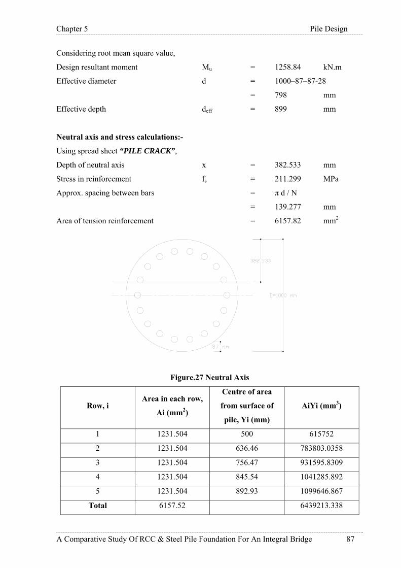
Chapter 5 Pile Design
A Comparative Study Of RCC & Steel Pile Foundation For An Integral Bridge 87
Considering root mean square value,
Design resultant moment Mu = 1258.84 kN.m
Effective diameter d = 1000–87–87-28
= 798 mm
Effective depth deff = 899 mm
Neutral axis and stress calculations:-
Using spread sheet “PILE CRACK”,
Depth of neutral axis x = 382.533 mm
Stress in reinforcement fs = 211.299 MPa
Approx. spacing between bars = π d / N
= 139.277 mm
Area of tension reinforcement = 6157.82 mm2
Figure.27 Neutral Axis
Row, i Area in each row,
Ai (mm2)
Centre of area
from surface of
pile, Yi (mm)
AiYi (mm3)
1 1231.504 500 615752
2 1231.504 636.46 783803.0358
3 1231.504 756.47 931595.8309
4 1231.504 845.54 1041285.892
5 1231.504 892.93 1099646.867
Total 6157.52 6439213.338

Chapter 5 Pile Design
A Comparative Study Of RCC & Steel Pile Foundation For An Integral Bridge 88
C.G. of tension reinforcement = 726.28 mm
Width of section at C.G. of tension reinforcement = 891.72 mm
Distance from compression face, a = 1000 mm
Distance to the surface of nearest bar, acr = 108.68 mm
Strain at level considered, ε1 = 0.00126
Average steel strain, εm = 0.00108
Design surface crack width, Wcr = 0.33 mm
Permissible crack width = 0.004 times clear
(As per IS: 4651-1989 part 4 Cl. 8.3.4) cover
= 0.348 mm
Therefore O.K.
Crack Width Check Summary:
Table-18.1 GRID A
Member Fx
(kN)
My
(kN.m)
Mz
(kN.m)
Mu
(kN.m)
N.A.
(mm)
Stress in
R/F.(N/mm2)
Crackwidth
(mm)
220 2099 1202 374 1258.840737 382.16 211.738 0.33
4774 554 503 364 620.8904895 318.65 150.016 0.21
220 2194 721.7 220 754.4871702 525.12 59.175 0.06
4774 649 250 243 348.6387815 368.55 71.314 0.05
220 2289 233 64.6 241.7894952 1104.79 -6.5 0
4774 1050 171.4 36.6 175.2641435 869.931 0.68 0
4482 2945 397 91 407.2959612 961.873 -3.35 0
4774 840 255 97 272.8259518 524.993 23.148 0
4532 2453.6 947.2 300 993.5732686 439.925 134.182 0.19
4824 954 491 333 593.2705959 344.01 140.79 0.19
4534 2492 522 169 548.6756783 724.187 14.67 0
4826 994 265 189 325.4934715 520.973 28.24 0
4536 2532 153 51 161.2761607 1505.56 -12.78 0
4828 1033 76 58 95.60334722 1195.56 -3.68 0
480 2617 5 2 5.385164807 28388.4 -21.59 0
4830 1072 1 3 3.16227766 17635.9 -8.76 0

Chapter 5 Pile Design
A Comparative Study Of RCC & Steel Pile Foundation For An Integral Bridge 89
Table-18.2 GRID B
Member Fx
(kN)
My
(kN.m)
Mz
(kN.m)
Mu
(kN.m)
N.A.
(mm)
Stress in
R/F.(N/mm2)
Crackwidth
(mm)
221 2340 1189 379 1247.943108 393.21 204.57 0.32
4775 717 501 233 552.5305421 344.29 115.75 0.15
221 2435 712 749 1033.414244 550.25 53.46 0.03
4775 1097 430 454 625.3127218 433.24 63.63 0.04
221 2530 227 241 331.0740099 1171.24 -8.59 0
4775 1192 179 186 258.1414341 902.68 0.09 0
4483 2528.7 396 404 565.7137085 890.88 0.43 0
4775 1005 255 259 363.4638909 639.91 11.73 0
4484 2575 939 968 1348.608542 465.77 113.18 0.15
4776 1117 490 503 702.2172029 408.9 81.01 0.08
4486 2614 517 533 742.5483149 765.42 10.37 0
4778 1257 263 296 395.9608567 688.43 10.03 0
4488 2653 151 156 217.1105709 1587.39 -14.06 0
4780 1296 75 86 114.1095964 1463.56 -6.35 0
384 2858 6 6 8.485281374 30956.7 -23.6 0
4782 1520 4 5 6.403124237 17380.1 -10.4 0
5.3 Geotechnical Design Of Steel Piles 5.3.1 Calculation Of Soil Spring Constant :
Soil spring stiffness calculation is same as that for RCC piles. So it is not presented here.
5.3.2 Pile Capacity Calculations:
From analysis of structure, it is found that maximum axial load in working condition is 2823
kN in operating case and 2660 kN in extreme case.
Pile capacity is checked for above value of axial load required to be transmitted. Bearing
capacity of piles is calculated as per procedure given in Clause of 6.4 of API RP 2A-WSD.
Ultimate Skin Resistance Qs = (α*C + K*Po*tanδ) kN/m2
Ultimate End Bearing Capacity Qb = (9*C + Po*Nq) kN/m2
Ultimate Bearing Capacity Of Soil Qu = Qs + Qb-W kN/m2
Where,
α = a dimensionless factor,

Chapter 5 Pile Design
A Comparative Study Of RCC & Steel Pile Foundation For An Integral Bridge 90
C = undrained shear strength of soil at point in question,
K = coefficient of lateral earth pressure,
Po = effective overburden pressure at point in question,
δ = friction angle between soil and pilewall,
W = weight of pile,
γ = effective unit weight of soil,
Nq = dimensionless bearing capacity factor.
Factor α = 0.5 Ψ-0.5 for Ψ ≤ 1.0
= 0.5 Ψ-0.25 for Ψ > 1.0 provided that α ≤ 1.0
Where Ψ = C / Po
Soil data for input:
Design sea bed level = (+) 1.15 m
Refer Table-16 for soil properties.
Skin frictional resistance:
Layer 1:
Level of water table = (+) 5.10 m CD
Length of pile above bed level = 11.245 m
Factor of safety = 2.0
Pile outer diameter = 1.016 mm
Pile tip thickness = 20 mm
Pile inner diameter = 0.976 mm
Pile tip area (annular) = 0.063 m2
Pile tip are (inner) = 0.748 m2
Outer pile perimeter = 3.191 m2
Inner pile perimeter = 3.066 m2
Layer thickness = 6.53 m
γsub = 7.75 kN/m3
C = 150 kN/m2
Angle of internal friction = 0 deg
Wall friction between soil and pile = 0 deg
Co-efficient of lateral earth pressure = 0.8
Effective over burden pressure at top of layer = 0 kN/m2
Effective over burden pressure at bottom of layer = 50.6075 kN/m2
Outer surface area = 20.83 m2

Chapter 5 Pile Design
A Comparative Study Of RCC & Steel Pile Foundation For An Integral Bridge 91
Inner surface area = 20.02 m2
Reduction factor α:
Ψ = C / Po
Ψtop = 0, αtop = 0 = 0
Ψbottom = 2.964, αbottom = 0.5 Ψ-0.25 = 0.381
Average reduction factor α = 0.190
Outer skin friction Qsfo1 = 593.65 kN
Inner skin friction Qsfi1 = 570.57 kN
Layer 2:
Layer thickness = 9 m
γsub = 7.75 kN/m3
C = 80 kN/m2
Angle of internal friction = 0 deg
Wall friction between soil and pile = 0 deg
Co-efficient of lateral earth pressure = 0.8
Effective over burden pressure at top of layer = 50.6075 kN/m2
Effective over burden pressure at bottom of layer = 120.35 kN/m2
Outer surface area = 28.719 m2
Inner surface area = 27.594 m2
Reduction factor α:
Ψ = C / Po
Ψtop = 1.58, αtop = 0.5 Ψ-0.25 = 0.445
Ψbottom = 0.664, αbottom = 0.5 Ψ-0.5 = 0.613
Average reduction factor α = 0.529
Outer skin friction Qsfo2 = 1215.38 kN
Inner skin friction Qsfi2 = 1167.77 kN
Layer 3:
Layer thickness = 7.5 m
γsub = 7.75 kN/m3
C = 160 kN/m2
Angle of internal friction = 0 deg
Wall friction between soil and pile = 0 deg
Co-efficient of lateral earth pressure = 0.8
Effective over burden pressure at top of layer = 120.35 kN/m2

Chapter 5 Pile Design
A Comparative Study Of RCC & Steel Pile Foundation For An Integral Bridge 92
Effective over burden pressure at bottom of layer = 178.48 kN/m2
Outer surface area = 28.719 m2
Inner surface area = 27.594 m2
Reduction factor α:
Ψ = C / Po
Ψtop = 1.32, αtop = 0.5 Ψ-0.25 = 0.466
Ψbottom = 0.89, αbottom = 0.5 Ψ-0.5 = 0.529
Average reduction factor α = 0.4975
Outer skin friction Qsfo3 = 1903. 12 kN
Inner skin friction Qsfi3 = 1828.19 kN
Layer 4:
Layer thickness = 2 m
γsub = 7.75 kN/m3
C = 0 kN/m2
Angle of internal friction = 35 deg
Wall friction between soil and pile = 24.5 deg
Co-efficient of lateral earth pressure = 0.8
Effective over burden pressure at top of layer = 178.48 kN/m2
Effective over burden pressure at bottom of layer = 193.98 kN/m2
Average over burden pressure at bottom of layer = 186.23 kN/m2
Outer surface area = 6.38 m2
Inner surface area = 6.132 m2
Outer skin friction Qsfo4 = 426.60 kN
Inner skin friction Qsfi4 = 409.54 kN
End Bearing Resistance:
Annular end bearing Qba = 193.98 x 40 x 0.063 = 488.82 kN
Inner end bearing Qbi = 193.88 x 40 x 0.7481 = 5801.66 kN
Total outer skin friction Qsfo = 4084 kN
Total inner skin friction Qsfi = 3920 kN
< Inner end bearing.
Therefore plug is not formed.
Total ultimate bearing capacity = Qsfo + Qsfi + Qba = 8482.41 kN
Weight of Pile:

Chapter 5 Pile Design
A Comparative Study Of RCC & Steel Pile Foundation For An Integral Bridge 93
Weight of pile above scour level Wp1 = 55.63 kN
Weight of pile below scour level Wp2 = 112.33 kN
Allowable load = ((8482.41 – 112.33)/2) – 55.63 = 4134.23 kN
From above calculations,
Required depth = 26.03 m below design sea bed level
E.G.L. = (+) 1.15 m
Total depth below E.G.L. = 26.03 m
Level at this depth = (-) 24.88 m
Allowable load at this level = 4134 kN > 3000 kN.
This value is also useful for finding out value of spring stiffness at the bottom of pile.
Assuming 10 mm settlement,
Stiffness = Load / settlement
= 4134/0.01
=413400 kN/m
5.4 Structural Design Of Steel Piles Design of steel pile section is done with working stress method. Design is done in accordance
with API RP-2A WSD. Design is checked for all possible severe combination of resultant
forces and design is presented for a typical governing force combination (moment and axial
force combination).
Design of piles is done using spread sheet “API STEEL PILE DESIGN”. A typical design is
presented here.
5.4.1 Typcial Design For Operating Case:
Basic Inputs:-
Outside diameter of pile D’o = 1.016 m
Corrosion Allowance = 5 mm
Corroded outside diameter Do = 1.011 m
Structural thickness t = 17 mm
Inside diameter of pile Di = 0.977 m
Unsupported length of pile L = 13.0 m
Effective length factor K = 1.2
Grade of steel Fy = 240 N/mm2
Modulus of elasticity E = 200000 N/mm2

Chapter 5 Pile Design
A Comparative Study Of RCC & Steel Pile Foundation For An Integral Bridge 94
Loads:-
Axial force Pu = 2353 kN
Moment My Mx = 1119 kN.m
Moment Mz Mz = 388 kN.m
Considering root mean square value,
Design resultant moment Mu = 1184 kN.m
Effective length of pile Leff = 1.2*13
= 15.6 m
Compressive stress
Cross sectional area A = ∏/4 (Do2–Di
2)
= 53086.63 mm2
Actual compressive stress fa = P / A
= 44.32 N/mm2
Elastic local buckling stress Fxe = 2CEt/Do N/mm2
(API RP 2A-WSD Cl.3.2.2.b)
Where C = critical elastic buckling co-efficient = 0.3
Fxe = 2017 N/mm2
Inelastic local buckling stress Fxc = lesser of Fxc1 and Fxc2
(API RP 2A-WSD Cl.3.2.2.b)
Where Fxc1 = Fy x [1.64 – 0.23(Do/t)1/4]≤ Fxe, Fxc2 = Fy
Fxc1 = 240.3 N/mm2
Fxc2 = 240 N/mm2
Therefore, Fxc = 240 N/mm2
Bending Stress
Moment of inertia I = ∏/64 (Do4–Di
4)
= 6558355778 mm4
Section Modulus Z = I / (Do/2)
= 12973997.58 mm3
Actual bending stress fb = M/Z
= 91.259 N/mm2
Since (10340/Fy) < (Do/t) = 67.4 < (20680/Fy),
Allowable bending stress Fb = [0.84 – 1.74 (FyDo) / (Et)] Fy
= 171.80 N/mm2
Check for combined stresses

Chapter 5 Pile Design
A Comparative Study Of RCC & Steel Pile Foundation For An Integral Bridge 95
0.16.0
≤+b
b
xc
a
Ff
Ff
(API RP 2A-WSD Cl.3.3.1.b)
b
b
xc
a
Ff
Ff
+6.0
= 0.30 + 0.53 = 0.83 ≤ 1. Therefore OK.
5.4.2 Typcial Design For Extreme Case:
Basic Inputs:-
Outside diameter of pile D’o = 1.016 m
Corrosion Allowance = 5 mm
Corroded outside diameter Do = 1.011 m
Structural thickness t = 15 mm
Inside diameter of pile Di = 0.981 m
Unsupported length of pile L = 13.0 m
Effective length factor K = 1.2
Grade of steel Fy = 240 N/mm2
Modulus of elasticity E = 200000 N/mm2
Loads:
Axial force Pu = 2660 kN
Moment My Mx = 333 kN.m
Moment Mz Mz = 1347 kN.m
Considering root mean square value,
Design resultant moment Mu = 1387 kN.m
Compressive stress
Cross sectional area A = ∏/4 (Do2–Di
2)
= 46935.39 mm2
Actual compressive stress fa = P / A
= 56.67 N/mm2
Elastic local buckling stress Fxe = 2CEt/Do N/mm2
(API RP 2A-WSD Cl.3.2.2.b)
Where C = critical elastic buckling co-efficient = 0.3
Fxe = 1780 N/mm2
Inelastic local buckling stress Fxc = lesser of Fxc1 and Fxc2
(API RP 2A-WSD Cl.3.2.2.b)
Where Fxc1 = Fy x [1.64 – 0.23(Do/t)1/4]≤ Fxe,
Fxc2 = Fy

Chapter 5 Pile Design
A Comparative Study Of RCC & Steel Pile Foundation For An Integral Bridge 96
Fxc1 = 235 N/mm2
Fxc2 = 240 N/mm2
Therefore, Fxc = 235 N/mm2
Bending Stress
Moment of inertia I = ∏/64 (Do4–Di
4)
= 5821402815 mm4
Section Modulus Z = I / (Do/2)
= 11516128.22 mm3
Actual bending stress fb = M/Z
= 120..43 N/mm2
Since (10340/Fy) < (Do/t) = 67.4 < (20680/Fy),
Allowable bending stress Fb = [0.84 – 1.74 (FyDo) / (Et)] Fy
= 167 N/mm2
Check for combined stresses
33.16.0
≤+b
b
xc
a
Ff
Ff
(API RP 2A-WSD Cl.3.3.1.b)
b
b
xc
a
Ff
Ff
+6.0
= 0.401 + 0.721 = 1.122 ≤ 1.33. Therefore OK.
Check for shear stress:
Basic Inputs:-
Outside diameter of pile D’o = 1.016 m
Corrosion Allowance = 5 mm
Corroded outside diameter Do = 1.006 m
Structural thickness t = 11 mm
Inside diameter of pile Di = 0.984 m
Loads:
Shear Force Fx = 230.17 kN
Shear Force Fz = 56.564 kN
Considering root mean square value,
Design resultant shear force Fu = 237 kN
Area of cross section A = 34384.73 mm2
Actual Shear stress fv = Fu / 0.5A
= 13.78 N/mm2

Chapter 5 Pile Design
A Comparative Study Of RCC & Steel Pile Foundation For An Integral Bridge 97
Allowable shear stress Fv = 0.4 Fy
(API RP 2A-WSD Cl.3.2.4.a)
= 96 N/mm2
> 13.78 N/mm2.
5.4.3 Minimum Wall Thickness:
As per Cl.6.10.6 of API RP 2A-WSD, the D/t ratio of the entire length of a pile should be
small enough to preclude local buckling at stresses up to the yield strength of the pile material.
Consideration should be given to the different loading situations occurring during the
installations and service life of a piling. For piles that are to be installed by driving where
sustained hard driving is anticipated, the minimum piling wall thickness used should not be
less than
t = 6.35 + D/100
where t= thickness (mm)
D= diameter (mm)
For diameter of 1016 mm, t = 6.35 + 1016/100 = 16.51mm.
<18mm(provided thickness)
5.4.4 Corrosion Allowance:
Corrosion allowance in terms of additional steel plate thickness is added to the structural
thickness. Corrosion allowance is considered in accordance with BS:6349 -1:2000 ‘Maritime
Structures-Code Of Practice For General Criteria’.
Marine environment usually include several exposure zones with differing degrees of
aggressiveness. The corrosion performance of maritime structures therefore requires separate
consideration in each of these zones. The average and upper limit values for the different
exposure zones are given in Table 19. The rates apply to each face exposed to environment of
the zone. The rates given in the table should be regarded to the uniform or general corrosion
and can be used to assess the theoretical design life of the structure.

Chapter 5 Pile Design
A Comparative Study Of RCC & Steel Pile Foundation For An Integral Bridge 98
Table-19 Rates Of Corrosion For Structural Steel
Exposure Zone
Corrosion Rate
mm/side/year
Mean Upper
Limit
Atmospheric Zone:
Above splash zone and where direct wave or spray impingement is
infrequent
0.04 0.1
Splash Zone:
Above mean high water to a height depending on mean wave height
and exposure to wind
0.08 0.17
Tidal Zone:
Between mean high water and mean low water spring level 0.04 0.1
Inter-tidal Low Water Zone:
Between low water spring and 0.5m below LAT 0.08 0.17
Continuous Sea Water Immersion Zone:
From 0.5 m below LAT to sea bed level 0.04 0.13
Below Sea Bed Level Or In Contact With Soil 0.015

Chapter 5 Pile Design
A Comparative Study Of RCC & Steel Pile Foundation For An Integral Bridge 99
5.4.5 Pile Design Summary:
Table-20.1 GRID A
R.L.
Reqd. Thk.
(Operating)
(mm)
Reqd. Thk.
(Extreme)
(mm)
Max.
Reqd.
Thk. (mm)
Corrosion
Allowance
(mm)
Total
Reqd. Thk.
(mm)
14.246 16 16 16 5 21
13.159 15 14 15 5 20
12.059 14 13 14 5 19
10.972 13 11 13 5 18
9.885 12 10 12 8.5 20.5
8.785 11 8 11 5 16
7.698 10 7 10 5 15
6.611 9 6 9 5 14
5.485 10 6 10 5 15
4.424 11 8 11 5 16
2.683 12 9 12 5 17
2.237 13 11 13 5 18
1.150 15 13 15 5 20
0.150 15 13 15 0.75 15.75
-1.850 15 12 15 0.75 15.75
-3.850 12 8 12 0.75 12.75
-5.850 10 6 10 0.75 10.75
-7.850 9 6 9 0.75 9.75
upto -24 9 6 9 0.75 9.75

Chapter 5 Pile Design
A Comparative Study Of RCC & Steel Pile Foundation For An Integral Bridge 100
Table-20.2 GRID B
R.L.
Reqd. Thk.
(Operating)
(mm)
Reqd. Thk.
(Extreme) (mm)
Max. Reqd.
Thk. (mm)
Corrosion
Allowance (mm)
Total
Reqd. Thk.
(mm)
14.246 17 16 17 5 22
13.159 16 15 16 5 21
12.059 15 13 15 5 20
10.972 14 12 14 5 19
9.885 13 10 13 8.5 21.5
8.785 11 9 11 5 16
7.698 10 7 10 5 15
6.611 9 6 9 5 14
5.485 9 6 9 5 14
4.424 10 8 10 5 15
2.683 12 9 12 5 17
2.237 13 11 13 5 18
1.150 15 13 15 5 20
0.150 15 12 15 0.75 15.75
-1.850 14 12 14 0.75 14.75
-3.850 12 11 12 0.75 12.75
-5.850 10 9 10 0.75 10.75
-7.850 9 7 9 0.75 9.75
upto -24 9 7 9 0.75 9.75
5.4.6 Provided Thickness:
As can be seen from pile design summary that there is minor difference between the thickness
requirements of grid A and grid B piles, both piles are given same spool lengths and
thicknesses. Spool length and thickness of each spool for one pile is given in table below:
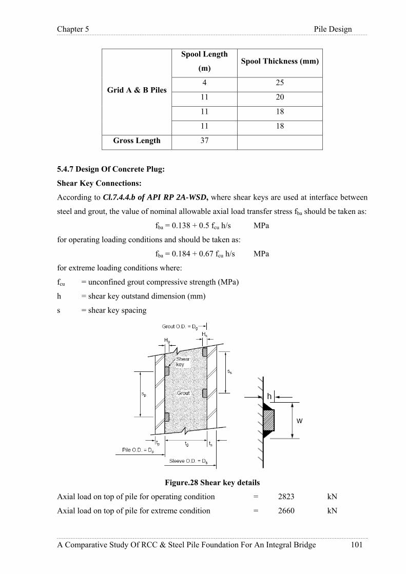
Chapter 5 Pile Design
A Comparative Study Of RCC & Steel Pile Foundation For An Integral Bridge 101
Grid A & B Piles
Spool Length
(m) Spool Thickness (mm)
4 25
11 20
11 18
11 18
Gross Length 37
5.4.7 Design Of Concrete Plug:
Shear Key Connections:
According to Cl.7.4.4.b of API RP 2A-WSD, where shear keys are used at interface between
steel and grout, the value of nominal allowable axial load transfer stress fba should be taken as:
fba = 0.138 + 0.5 fcu h/s MPa
for operating loading conditions and should be taken as:
fba = 0.184 + 0.67 fcu h/s MPa
for extreme loading conditions where:
fcu = unconfined grout compressive strength (MPa)
h = shear key outstand dimension (mm)
s = shear key spacing
Figure.28 Shear key details
Axial load on top of pile for operating condition = 2823 kN
Axial load on top of pile for extreme condition = 2660 kN

Chapter 5 Pile Design
A Comparative Study Of RCC & Steel Pile Foundation For An Integral Bridge 102
Nominal allowable load transfer stress fba for operating condition:
Assuming h = 20 mm
s = 300 mm
fba = 0.138 + 0.5 fcu h/s
= 0.138 + 0.5 x 40 x 20 / 300
= 1.47 MPa
Length of concrete plug required = 2823 x 1000 / (∏ x 966 x 1.47) = 632 mm
Nominal allowable load transfer stress fba for extreme condition:
fba = 0.184 + 0.67 fcu h/s
= 0.184 + 0.67 x 40 x 20 / 300
= 1.97 MPa
Length of concrete plug required = 2660 x 1000 / (∏ x 966 x 1.97) = 445 mm
Hence provide in-situ concrete plug of 1000mm length inside steel pile.
Design Of Shear Key:
Maximum axial force on top of pile = 2823 kN
Permissible bearing stress in concrete = 10 N/mm2
Nos. Of shear keys in 1m length of concrete plug = 3
Bearing area of 3 shear keys = ∏ x 977 x 20 x 3 = 184160.16 N/mm2
Capacity of shear keys in bearing = 184160.16x10/1000 = 1841 kN
< 2823 kN
Hence provide 4 shear keys of 25 mm thickness and 50 mm wide @ 200 mm c/c distance to
meet bearing criteria.
Bearing capacity of 4 shear keys = ∏ x 977 x 25 x 4 x 10 / 1000
= 3069 kN
> 2823 kN.
Hence OK.
According to Cl.7.4.4.c of API RP 2A-WSD, following limitations should be observed while
designing shear keys:
17.25 MPa ≤ fcu = 40 MPa ≤ 110 MPa
Shear key ratio h/s = 0.1 ≤ 0.1
Shear key shape factor 1.5 ≤ w/h=2 ≤ 3
Product of fcu and h/s = 4 ≤ 5.5 MPa.
Hence shear key dimension and spacing is satisfying all above stated limitations.
Weld Design:

Chapter 5 Pile Design
A Comparative Study Of RCC & Steel Pile Foundation For An Integral Bridge 103
Axial force to be transferred through each shear key = 705750 N
Assumed size of fillet weld = 6 mm
Effective throat thickness = 0.707 x 6 = 4.24 N/mm2
Permissible shear stress in fillet weld = 108 N/mm2
Length required for weld =705750 / (4.242 x 10⁸) = 1540 mm.
5.4.8 Design Of Concrete Plug:
Design of plug is done as per IS:456-2000 & SP 16. Design is checked for all possible severe
combination of resultant forces and design is presented for a typical governing force
combination (moment and axial force combination).
Design of insitu concrete plug is done using spread sheet “PILE DESIGN”. A typical design
is presented here.
Basic Inputs:-
Diameter of pile D = 0.966 m
Unsupported length of pile L = 13.00 m
Effective length factor = 1.2
Grade of concrete fck = 40 N/mm2
Grade of steel fy = 500 N/mm2
Dia. of bar assumed Ф = 28 mm
Dia. of helicals assumed Фh = 12 mm
Clear cover to outermost reinforcement, d = 75 mm
Loads:-
Axial force Pu = 3013 kN
Moment My Mx = 227 kN.m
Moment Mz Mz = 2267 kN.m
Considering root mean square value,
Design resultant moment Mu = 2278 kN.m
Effective length of pile Leff = 1.2*13
= 15.6 m
Effective cover d' = 101 mm
Area of pile Ag = 0.73289909 m2
Area of pile core Acr = 31741.60 m2
Minimum eccentricity
e = (L/500) + (D/30) ≥ 20 mm e = 58.2 mm
Me = 112/26 kN.m
Chapter 5 Pile Design
A Comparative Study Of RCC & Steel Pile Foundation For An Integral Bridge 104
< Mu
Therefore Final actual moments Me = 1924 kN.m
The section is now checked for biaxial bending:-
Pu / fck D2 = 0.08
Mux / fck D3 = 0.063
From SP:16 chart 59 to 62, Pt / fck = 0.05
Therefore Pt = 2.0 %
Ast required = 14657.98 mm2
Minimum reinforcement required = 0.80%
= 5863.19 mm2
Dia of bars provided = 32 mm
No. of bars provided = 19
Ast provided = 11699.29 mm2
Design of helical reinforcement
Dia. of helicals required = max. of 6 mm or
Dia. of main bar/4
= 7 mm
Pitch required = 150 mm
Dia. of helicals provided = 12 mm
Pitch provided = 150 mm
Development Length
Ld = Ф σs / 4 τbd
Bond stress = 1.5 N/mm2
60% increase for deformed bars
Design bond stress = 2.4 N/mm2
Stress in bar σs = 0.87 fy = 435 N/mm2
Development Length Ld = 46.00 times dia
Concrete Plug Design Summary:
Table-21
PILE R/F
Grid A 19-32mmФ
Grid B 17-32mmФ

Chapter 5 Pile Design
A Comparative Study Of RCC & Steel Pile Foundation For An Integral Bridge 105
5.4.9 Check For Serviceability:
Piles are checked for serviceability under all possible severe combination of working loads.
Deflections at top of piles are summarized in table below.
Load Combination Deflection (mm)
Operating 48
Seismic 75.5
Storm 66
As per Cl. 43.2 IS:456-2000, Cracks due to bending in a compression member subjected to a
design axial load greater than 0.2fckAc, where fck is the characteristic compressive strength of
concrete and Ac is the area of the gross section of the member, need not be checked.
Here, maximum axial load on the pile = 4044 kN
< 0.2*40*785398.1634 = 6283.185 kN
Therefore check for crack width must be done.
Crack width is found out as per Annex F IS: 456-2000.
Design surface crack width,
xhCa
aW
cr
mcrcr
−−
+=
)(21
3min
ε
Where,
acr = distance from point considered to the surface of the nearest
longitudinal bar.
Cmin = clear cover to main reinforcement
h = overall depth of the member
x = depth of neutral axis
εm = average steel strain given by,
)(3))((
1 xdAExaxhb
ssm −
−−−= εε
Where,
As = area of tension steel
b = width of the section
a = distance from the compression face to the point at which crack width is
being calculated.

Chapter 5 Pile Design
A Comparative Study Of RCC & Steel Pile Foundation For An Integral Bridge 106
ε1 = strain at level considered ignoring the stiffening of the concrete in the tension
zone.
Es = Young’s modulus for steel
Basic Inputs:-
Diameter of pile h = 0.966 m
Grade of concrete fck = 40 N/mm2
Grade of steel fy = 500 N/mm2
Dia. of main reinforcement Ф = 28 mm
No. of bars N = 19
Dia. of helicals Фh = 12 mm
Clear cover to outermost reinforcement = 75 mm
Clear cover to main reinforcement Cmin = 87 mm
Loads:-
Axial force Pu = 2206 kN
Moment My Mx = 1175 kN.m
Moment Mz Mz = 94 kN.m
Considering root mean square value,
Design resultant moment Mu = 1178 kN.m
Effective diameter d = 966 – 87 – 87 – 28
= 764 mm
Effective depth deff = 865 mm
Neutral axis and stress calculations:-
Using spread sheet “PILE CRACK”,
Depth of neutral axis x = 391.334 mm
Stress in reinforcement fs = 186.24 MPa
Approx. spacing between bars = π d / N
= 126.32 mm
Area of tension reinforcement = 48629 mm2

Chapter 5 Pile Design
A Comparative Study Of RCC & Steel Pile Foundation For An Integral Bridge 107
Figure.29 Concrete Plug Neutral Axis
C.G. of tension reinforcement = 686.83 mm
Width of section at C.G. of tension reinforcement = 875.76 mm
Distance from compression face, a = 966 mm
Distance to the surface of nearest bar, acr = 105.12 mm
Strain at level considered, ε1 = 0.00112
Average steel strain, εm = 0.0009
Design surface crack width, Wcr = 0.29 mm
Permissible crack width = 0.004 times clear cover
(As per IS: 4651-1989 part 4 Cl. 8.3.4)
= 0.348 mm
Therefore O.K.
Crack Width Check Summary:
Table-22.1 GRID A
Beam Fx
(kN)
My
(kN.m)
Mz
(kN.m)
Mu
(kN.m)
N.A.
(mm)
Stress in
reft.(N/mm2)
Crackwidth
(mm)
220 122 2206 1175 94 391.33 186.24 0.29
4774 133 848 648 295 335.56 154.55 0.22
Table-22.2 GRID B
Beam Fx
(kN)
My
(kN.m)
Mz
(kN.m)
Mu
(kN.m)
N.A.
(mm)
Stress in
reft.(N/mm2)
Crackwidth
(mm)
221 127 2353 1119 388 343.61 159.13 0.23
4775 121 1036 743 252 393.47 191.38 0.30

CHAPTER 6
COMPARISON OF RESULTS

Chapter 6 Comparison Of Results
A Comparative Study Of RCC & Steel Pile Foundation For An Integral Bridge 108
6.1 Comparison Between Various Steel Pile Diameters: 6.1.1 Without restricted deflection:
Here, comparision of weight between 4 different diameters is done keeping total structural
thickness equal to what is required from strength point of view.
Table 23 Weight Comparision
O.D. (mm) Spool Details (Length - Thickness)
Total Weight(T)Spool-1 Spool-2 Spool-3 Spool-4
1016 4m-25mm 11m-20mm 11m-18mm 11m-18mm 17.6
1118 4m-25mm 11m-20mm 11m-18mm 11m-18mm 19.4
914 11m-25mm 4m-20mm 11m-18mm 11m-18mm 16.5
813 11m-25mm 4m-25mm 11m-18mm 11m-18mm 15
Table 24 Deflection Comparision
Pile Options Load Case
Operating Seismic Storm
1000mm Dia. RCC 46 68 60
1118mm O.D. Steel 46 74 58
1016mm O.D. Steel 49 79 69
914mm O.D. Steel 52 86 84
813mm O.D. Steel 58 100 106
Table 25 Founding Level Comparision
Pile Options Founding Level
(m CD)
1000mm Dia. RCC (-)25.00
1118mm O.D. Steel (-)25.00
1016mm O.D. Steel (-)25.00
914mm O.D. Steel (-)25.00
813mm O.D. Steel (-)25.00
6.1.2 With Restricted Deflection:
As mentioned in Chapter 3 – Project Description, deflection at top of deck in operating
condition is to be restricted to 50mm for proper functioning of material handling system
installed over deck, plate thickness were revised to suit this limit. Analysis and design with
increased structural thickness is done for pile diameters 914mm and 813m as for other two
diameters, deflection is well within limit.

Chapter 6 Comparison Of Results
A Comparative Study Of RCC & Steel Pile Foundation For An Integral Bridge 109
Table 26 Weight Comparision
O.D. (mm) Spool Details (Length - Thickness)
Total Weight(T)Spool-1 Spool-2 Spool-3 Spool-4
1016 4m-25mm 11m-20mm 11m-18mm 11m-18mm 17.6
914 11m-28mm 4m-25mm 11m-20mm 11m-18mm 18.5
813 11m-34mm 4m-32mm 11m-30mm 11m-30mm 22.39
Table 27 Deflection Comparision
Pile Options Load Case
Operating Seismic Storm
1016mm O.D. Steel 49 79 69
914mm O.D. Steel 50 83 75
813mm O.D. Steel 50 85 75
6.2 Comparison Of Forces In Pile:
MOMENT COMPARISION FOR OPERATING LOADCASES
0200400600800
100012001400
0 0.083 0.167 0.25 0.333 0.417 0.5 0.583 0.667 0.75 0.833 0.917 1
H/L
MO
ME
NT (K
N.M
)
RCC Steel
MOMENT COMPARISION FOR SEISMIC LOADCASES
0
500
1000
1500
2000
2500
0 0.083 0.167 0.25 0.333 0.417 0.5 0.583 0.667 0.75 0.833 0.917 1
H/L
MO
ME
NT
(KN
.M)
RCC STEEL
H = length of segment measured from top of pile, L = Total length up to fixity measured from pile top.

Chapter 6 Comparison Of Results
A Comparative Study Of RCC & Steel Pile Foundation For An Integral Bridge 110
MOMENT COMPARISION FOR STORM LOADCASES
0
500
1000
1500
2000
0 0.083 0.167 0.25 0.333 0.417 0.5 0.583 0.667 0.75 0.833 0.917 1
H/L
MO
ME
NT (K
N.M
)RCC STEEL
MOMENT COMPARISION
0
500
1000
1500
2000
2500
0 0.083 0.167 0.25 0.333 0.417 0.5 0.583 0.667 0.75 0.833 0.917 1
H/L
MO
MEN
T (K
N.M
)
RCC OPERATING RCC SEISMIC RCC STORMSTEEL OPERATING STEEL SEISMIC STEEL STORM
SHEAR FORCE COMPARISION FOR OPERATING LOADCASES
0
50
100
150
200
0 0.083 0.167 0.25 0.333 0.417 0.5 0.583 0.667 0.75 0.833 0.917 1
H/L
SHEA
R FO
RCE
(KN
)
RCC STEEL

Chapter 6 Comparison Of Results
A Comparative Study Of RCC & Steel Pile Foundation For An Integral Bridge 111
SHEAR FORCE COMPARISION FOR SEISMIC LOADCASES
050
100150200250300
0 0.083 0.167 0.25 0.333 0.417 0.5 0.583 0.667 0.75 0.833 0.917 1
H/L
SHEA
R FO
RCE
(KN
)RCC STEEL
SHEAR FORCE COMPARISION FOR STORM LOADCASES
050
100150200250300
0 0.083 0.167 0.25 0.333 0.417 0.583 0.5 0.667 0.75 0.833 0.917 1
H/L
SHEA
R FO
RCE
(KN
)
RCC STEEL
AXIAL FORCE COMPARISION
2600
2650
2700
2750
2800
OPERATING SEISMIC STORM
LOADING CONDITION
AXIA
L FO
RCE
(KN)
RCC STEEL

Chapter 6 Comparison Of Results
A Comparative Study Of RCC & Steel Pile Foundation For An Integral Bridge 112
6.3 Comparison Of Deflection In Pile
DEFLECTION COMPARISION
0
20
40
60
80
100
OPERATING SEISMIC STORM
LOADING CONDITION
DEF
LEC
TIO
N (M
M)
RCC STEEL
6.4 Comparison Of Forces In Beams
COMPARISION OF FORCES FOR PILE-CAP BEAM
01000200030004000
Hogging atsupport (KN.m)
Sagging atsupport (KN.m)
Sagging at mid-span (KN.m)
Shear atsupport (KN)
FORCES
VAL
UE
RCC Steel
COMPARISION OF FORCES FOR LONGITUDINAL BEAMS
0
500
1000
1500
Hogging at support(KN.m)
Sagging at mid-span(KN.m)
Shear at support(KN.m)
FORCES
VAL
UE
RCC STEEL

CHAPTER 7
CONCLUSION AND FUTURE SCOPE

Chapter 7 Conclusion & Future Scope
A Comparative Study Of RCC & Steel Pile Foundation For An Integral Bridge 113
7.1 Conclusion: Following conclusions are derived based on the present work.
For required structural thickness, 914mm O.D. pile and 813mm O.D. pile are weighing
6.25% and 14.77% less than 1016mm O.D. pile respectively. And 1118 mm O.D. pile
is weighing 10.22% more than 1016mm O.D. pile.
But deflection is limited to 50mm in operating condition at top of deck for proper
functioning of the material handling system installed above deck. Deflection is higher
than this limit in 914mm O.D. pile and 813mm O.D. pile. To reduce deflection,
thickness needs to be increased. With increased thickness (by providing thickness
required to reduce deflection to 50mm), 914mm O.D. pile and 813mm O.D. pile are
weighing 5.11% and 27.21% more than 1016mm O.D. pile respectively. Thus it can be
concluded that for given deflection limit, 1016mm O.D. pile option is most economical
steel pile for the structure studied in this thesis.
Founding level of all the three steel piles are coming same as piles are founded in sand
layer to avoid founding into clay layer which is considered as weak for end bearing.
All three piles are penetrated into sand layer by 2m as per guidelines given in API RP
2A-WSD.
Founding level of 1.0m dia. bored cast in situ RCC pile and 1.016m outer dia. steel
piles is coming same because of avoiding founding into clay. Because static
calculation shows formation of soil plug inside steel pile which reduces pile bearing
capacity and there is large reduction in the end bearing resistance in clayey soil in case
of RCC piles. At same founding, level hollow steel pile gives more bearing capacity
than that of solid RCC pile. This is because skin friction is available on outer side as
well as on inner side of the steel pile whereas it is available only at outer side of the
RCC pile.
In comparison between 1.0m dia. bored cast in situ RCC pile and 1.016m outer dia.
steel pile, it can be seen that forces are almost same in both the cases except for
seismic load case where slight variation in forces is observed. Moments are approx.
6% higher in steel pile and shear force is approx. 8% higher in steel in seismic load
case.
Base shear co-efficient for RCC pile is 0.04 whereas for steel pile is 0.05. Although
hollow steel piles are flexible foundation compared to solid RCC pile but

Chapter 7 Conclusion & Future Scope
A Comparative Study Of RCC & Steel Pile Foundation For An Integral Bridge 114
multiplication of damping factor of value 1.4 with base shear coefficient increases
seismic force in steel piled structures as compared to RCC piles structure.
Moment of inertia (I) of 1.0 m dia. RCC pile is approx. 7.4 times moment of inertia of
1.016m outer dia. steel pile. At the same time, modulus of elasticity (E) of steel
material is approx. 6.3 times E of RCC material. But product of EI for RCC pile is
only 1.16 times EI of steel pile. Because of this, there is not major variation in RCC
pile and steel pile option.
7.2 Future Scope: In this dissertation work, both steel pile and RCC pile options are analyzed by using
soil spring stiffness method. Same can be done by depth of fixity approach.
Bearing capacity of steel piles can be evaluated by dynamic methods.
Further research can be done on using batter driven steel pile for reducing deflection.
Further work can be done on economics of steel pile and RCC pile option.
Further studies can be done on other pile types such as precast RCC piles, precast
prestress piles etc.
Dynamic analysis can be carried out for the given structure for dynamic loads such as
waves, current, wind, earthquake are acting on the.

CHAPTER 8
REFERENCES

Chapter 8 References
A Comparative Study Of RCC & Steel Pile Foundation For An Integral Bridge 115
1. Arora K.R., “Soil Mechanics and Foundation Engineering”, Standard Publishers, Third
Edition.
2. Aswani M.G. and Vazirani V.N. and Ratwani M.M., “Design Of Concrete Bridges”,
Khanna Publishers
3. Babu P.V.Mayur and Bhandari N.M, “A Comparative Study of Integral Bridges versus
Simply Supported Bridge”
4. Bowles Joseph E., “Foundation Analysis and Design”, McGraw-Hill Companies, Inc., Fifth
Edition.
5. Broms Bengt B., “Design of Laterally Loaded Piles”.
6. Byrne Byron, “Driven Pipe Piles in Dense Sand”
7. Chen Wai Fah and Duan Lian, “Bridge Engineering Handbook”, CRC Press.
8. Connal John, “Integral Abutment Bridges – Australian and US Practice”
9. Dawson Thomas H., “Offshore Structural Engineering”, United Status Naval Academy
10. Duggal S.K., “Design of Steel Structures”, The McGraw-Hill Publishing Company
Liminted, Second Edition,
11. Elson W.K., “Design of Laterally Loaded Piles”.
12. Evans Keith Martin, “A Model Study of The End Bearing Capacity of Piles In Layered
Calcareous Soils”.
13. Flener Esra Bayoglu, “Soil Structure Interaction in Integral Bridges”.
14. Hambly E.C., “Bridge Deck Behavior”, E & F N Spon Publications, Second Edition.
15. Mistry Vasant C., “Integral Abutment and Jointless Bridges”
16. Mokwa R.L., “Analysis of Laterally Loaded Pile Groups”
17. Murthy V.N.S, “Soil Mechanics and Foundation Engineering”, Sri Kripa Technical
Consultants, Third Edition.
18. Nayak Narayan, “Foundation Design Manual”, Dhanpat Rai Publications, Fourth Edition
19. O’brien Eugene J. and Keogh Damien L., “Design Details Of Integral Bridges”.
20. Park R. and Paulay T., “Reinforced Concrete Structure”, John Willey And Sons
Publications.
21. Poulos H.G. and Davis E.H., “Pile Foundation Analysis and Design”, John Willey And
Sons Publications.
22. Prakash Shamsher and Sharma Hari D., “Pile Foundations in Engineering Practice”, John
Willey And Sons Publications.
23. Raina V.K., “Concrete Bridge Practice”, The McGraw-Hill Publishing Company Limited,
Second Edition.

Chapter 8 References
A Comparative Study Of RCC & Steel Pile Foundation For An Integral Bridge 116
24. Reynolds Charles E. and Steedman James C., “Reinforced Concrete Designer’s
Handbook”, E & F N Spon Publications, Tenth Edition.
25. API Recommended Practice 2A-WSD Recommended Practice For Planning, Designing
And Constructing Fixed Offshore Platforms – Working Stress Design
26. BS:6349(Part1)-2000 Maritime Structures- Code Of Practice For General Criteria.
27. Coastal Engineering Manual(Part VI)- 2006 Chapter5 – Fundamentals Of Design.
28. IRC:6-2000 Standard Specifications And Code Of Practice For Road Bridges. Section II-
Load And Stresses.
29. IRC:22-1986 Standard Specifications And Code Of Practice For Road Bridges. Section
VI- Composite Construction.
30. IS:1893(Part 1)-2002 Code Of Practice For Earthquake Resistant Design Of Structures-
General Provisions And Buildings.
31. IS:1893-1984 Criteria For Earthquake Resistant Design Of Structures.
32. IS:2062-1999 Steel For General Structural Purpose-Specification
33. IS:2911 (Part 1/Sec 2) – 1979 Code Of Practice For Design And Construction Of Piles,
Bored Cast In Situ Piles
34. IS:456-2000 Plain And Reinforced Concrete – Code Of Practice
35. IS:4651 (Part 4) -1989 Code Of Practice For Planning And Design Of Ports And
Harbours, General Design Considerations.
36. IS:800-1984 Code Of Practice For General Construction In Steel
37. IS:816-1969 Code Of Practice For Use Of Metal Arc Welding For General Construction
In Mild Steel
38. IS:875 (Part 1) – 1987 Code Of Practice For Design Loads (Other Than Earthquake 32.
Loads) For Buildings And Structures – Dead Loads
39. IS:875 (Part 2) – 1987 Code Of Practice For Design Loads (Other Than Earthquake
Loads) For Buildings And Structures – Imposed Loads
40. IS:875 (Part 3) – 1987 Code Of Practice For Design Loads (Other Than Earthquake
Loads) For Buildings And Structures – Wind Loads
41. SP:16-1980 Design Aids To IS:456-1978,
42. SP:34-1987 Handbook On Concrete Reinforcement And Detailing,
43. SP:64-2001 Explanatory Handbook On Code Of Practice For Design Loads (Other Than
Earthquake Loads) For Buildings And Structures – Wind Loads

APPENDIX ‐ A
WAVE FORCE CALCULATION CHARTS

Appendix A Wave Force Calculation Charts
A Comparative Study Of RCC & Steel Pile Foundation For An Integral Bridge 117 -
Figure.A.1 Values Of Kim.

Appendix A Wave Force Calculation Charts
A Comparative Study Of RCC & Steel Pile Foundation For An Integral Bridge 118 -
Figure. A.2 Values Of KDm.

Appendix A Wave Force Calculation Charts
A Comparative Study Of RCC & Steel Pile Foundation For An Integral Bridge 119 -
Figure. A.3 Values Of Sim.

Appendix A Wave Force Calculation Charts
A Comparative Study Of RCC & Steel Pile Foundation For An Integral Bridge 120 -
Figure. A.4 Values Of SDm.

Appendix A Wave Force Calculation Charts
A Comparative Study Of RCC & Steel Pile Foundation For An Integral Bridge 121 -
Figure. A.5 Values Of Фm For W=0.05.

Appendix A Wave Force Calculation Charts
A Comparative Study Of RCC & Steel Pile Foundation For An Integral Bridge 122 -
Figure. A.6 Values Of Фm For W=0.1.

Appendix A Wave Force Calculation Charts
A Comparative Study Of RCC & Steel Pile Foundation For An Integral Bridge 123 -
Figure. A.7 Values Of Φm For W=0.5.

Appendix A Wave Force Calculation Charts
A Comparative Study Of RCC & Steel Pile Foundation For An Integral Bridge 124 -
Figure. A.8 Values Of Фm For W=1.0.

Appendix A Wave Force Calculation Charts
A Comparative Study Of RCC & Steel Pile Foundation For An Integral Bridge 125 -
Figure. A.9 Values Of αm For W=0.05.

Appendix A Wave Force Calculation Charts
A Comparative Study Of RCC & Steel Pile Foundation For An Integral Bridge 126 -
Figure. A.10 Values Of αm For W=0.1.

Appendix A Wave Force Calculation Charts
A Comparative Study Of RCC & Steel Pile Foundation For An Integral Bridge 127 -
Figure. A.11 Values Of αm For W=0.5.

Appendix A Wave Force Calculation Charts
A Comparative Study Of RCC & Steel Pile Foundation For An Integral Bridge 128 -
Figure. A.12 Values Of αm For W=1.0.

APPENDIX ‐ B
SUPER STRUCTURE ANALYSIS & DESIGN

Appendix B Super-structure Analysis & Design
A Comparative Study Of RCC & Steel Pile Foundation For An Integral Bridge 129
B.1Super-structure Analysis: B.1.1 Pilecap Beam Analysis:
Figure.B.1 Longitudinal & Pile Cap Beam Arrangement
Structural Idealization and Analysis Results:
3D analysis carried out on the same structural model which is used for design of piles.
Following set of design forces depict the maximum forces taken at face (1m) of support (for
hogging, sagging and shear at support) and sagging at mid span and corresponding torsion is
added appropriately as given in IS:456 2000 Cl.41.4.2 (equivalent moment) and 41.3.1
(equivalent shear).
Equivalent BM, Me = Mu + Mt ; Mt = Tu * (1+(D/b))/1.7
Equivalent shear, Ve = Vu + (1.6*Tu/b)
Forces at a section 2.25m from centre of pile are also shown to see the possibility of
curtailment of main reinforcement.
Table B.1.1
Limit State Of Collapse
Force Beam L/C V/M
(kN/kN.m)
T
(kN.m)
Ve/Me
(kN/kN.m)
Hogging at face of support 4282 517 3590.00 562.33 4708
Sagging at face of support 4770 671 529.82 207.30 942.113
Shear at ‘d’ distance from face of
support 4282 460 2144.115 606.45 3357
Hogging at 2.25m from support 626 435 66.688 678.848 1416.8
Sagging at 2.25m from support 4280 489 1662.37 135.546 1932
Shear at 2.25m from support 4282 460 1955.03 606.45 3167.93
Sagging at mid span 4281 464 3011.56 665.57 4335.36

Appendix B Super-structure Analysis & Design
A Comparative Study Of RCC & Steel Pile Foundation For An Integral Bridge 130
Table B.1.2
Limit State Of Collapse
Force Beam L/C V/M
(kN/kN.m)
T
(kN.m)
Ve/Me
(kN/kN.m)
Sagging at mid span for stage-I - - 549.847 0 549.847
Sagging at mid span for stage-II 4281 185 1151.479 171.076 1491.761
Sagging at 2.25 from support for
stage-I - - 132.356 0 132.356
Sagging at 2.25 from support for
stage-II 4282 195 67.375 598.356 1252.00
Shear at ‘d’ distance from face of
support for L-shear check - - 1047 0 1047
Shear at 3m from support for L-
shear check - - 564 0 564
B.1.2 Longitudinal Beam Analysis:
3D analysis carried out on the same structural model which is used for analysis of pile
cap beams. Following set of design forces depict the maximum forces taken at face (1m) of
support (for hogging, sagging and shear at support) and sagging at mid span and
corresponding torsion is added appropriately as given in IS:456 2000 Cl.41.4.2 (equivalent
moment) and 41.3.1 (equivalent shear).
Equivalent BM, Me = Mu + Mt ; Mt = Tu * (1+(D/b))/1.7
Equivalent shear, Ve = Vu + (1.6*Tu/b)
Forces at a section 3m from centre of pile are also shown to see the possibility of
curtailment of main reinforcement.

Appendix B Super-structure Analysis & Design
A Comparative Study Of RCC & Steel Pile Foundation For An Integral Bridge 131
Girder 2 to 4
Table B.2.1
Limit State Of Collapse
Force Beam L/C SF/BM (KN/KNm)
Hogging at face of support 3554 435 934.119
Hogging at 3m from support 165 517 102.834
Sagging at mid span 4702 547 1531.8
Sagging at 3m from support 4432 513 1344.19
Shear at ‘d’ distance from face of support 4466 519 909
Shear at 3m from support 4651 541 577.5
Table B.2.2
Limit State Of Serviceability Force Beam L/C SF/BM (KN/KNm)
Sagging at mid span for stage-I - - 386.69
Sagging at mid span for stage-II 2244 225 612.55
Sagging at 3m from support for stage-I - - 312
Sagging at 3m from support for stage-II 4719 219 603
Shear at ‘d’ distance from face of support
for L-shear check - - 451
Shear at 3m from support for L-shear check - - 305.381
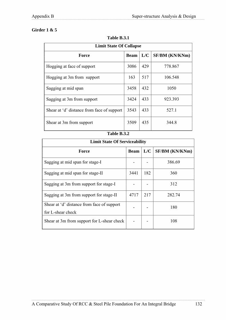
Appendix B Super-structure Analysis & Design
A Comparative Study Of RCC & Steel Pile Foundation For An Integral Bridge 132
Girder 1 & 5
Table B.3.1
Limit State Of Collapse
Force Beam L/C SF/BM (KN/KNm)
Hogging at face of support 3086 429 778.867
Hogging at 3m from support 163 517 106.548
Sagging at mid span 3458 432 1050
Sagging at 3m from support 3424 433 923.393
Shear at ‘d’ distance from face of support 3543 433 527.1
Shear at 3m from support 3509 435 344.8
Table B.3.2
Limit State Of Serviceability
Force Beam L/C SF/BM (KN/KNm)
Sagging at mid span for stage-I - - 386.69
Sagging at mid span for stage-II 3441 182 360
Sagging at 3m from support for stage-I - - 312
Sagging at 3m from support for stage-II 4717 217 282.74
Shear at ‘d’ distance from face of support
for L-shear check - - 180
Shear at 3m from support for L-shear check - - 108

Appendix B Super-structure Analysis & Design
A Comparative Study Of RCC & Steel Pile Foundation For An Integral Bridge 133
Girder 6 to 8
Table B.3.3
Limit State Of Collapse
Force Beam L/C SF/BM (KN/KNm)
Hogging at face of support 3091 429 651.667
Hogging at 3m from support 170 519 61.85
Sagging at mid span 4705 461 790.5
Sagging at 3m from support 4654 461 726.41
Shear at ‘d’ distance from face of support 3548 433 403.5
Shear at 3m from support 4350 513 226.4
Table B.3.4
Limit State Of Serviceability
Force Beam L/C SF/BM (KN/KNm)
Sagging at mid span for stage-I - - 386.69
Sagging at mid span for stage-II 4688 203 200
Sagging at 3m from support for stage-I - - 312
Sagging at 3m from support for stage-II 4722 203 181
Shear at ‘d’ distance from face of support
for L-shear check - - 112
Shear at 3m from support for L-shear check - - 69
B.1.3 End Diaphragm Analysis:
3D analysis carried out on the same structural model which is used for analysis of pile
cap beams.
Following set of design forces depict the maximum forces taken at face (1m) of
support (for hogging, sagging and shear at support) and sagging at mid span and

Appendix B Super-structure Analysis & Design
A Comparative Study Of RCC & Steel Pile Foundation For An Integral Bridge 134
corresponding torsion is added appropriately as given in IS:456 2000 Cl.41.4.2 (equivalent
moment) and 41.3.1 (equivalent shear).
Equivalent BM, Me = Mu + Mt ; Mt = Tu * (1+(D/b))/1.7
Equivalent shear, Ve = Vu + (1.6*Tu/b)
Table-B.4.1
Limit state of Collapse
Force Beam L/C SF/BM
(KN/KNm)
T
(KNm)
Ve/Me
(KN/KNm) Hogging at face of support 4765 545 1411 77 1514
Sagging at mid span 4762 547 1049 295 1440
Shear at face of support 4765 463 1003 101 1203
Table-B.4.2
Limit state of Serviceability
Force Beam L/CSF/BM
(KN/KNm)
T
(KNm)
Ve/Me
(KN/KN.m)
Sagging at mid span 4762 218 907 193 1164
B.1.4 Deck Slab Analysis:
Figure.B.2 Precast Deck Planks Arrangement
The deck slab is modeled in the STAAD as a rectangular beam of 1m width and 280 mm
depth. Vehicular loads are restricted within the road width of approach and a live load of 1.5
kN/m2 is considered in the rest. The vehicular load is placed at various positions in the
transverse direction and results are obtained as below:
Deck Plank DP1
Design sagging moment = 77.09 kNm
Design hogging moment = 60.6 kNm

Appendix B Super-structure Analysis & Design
A Comparative Study Of RCC & Steel Pile Foundation For An Integral Bridge 135
Design shear force = 250.5 kN
Serviceability shear = 157 kN
Serviceability moment = 51.3 kN
Deck Plank DP2
Design sagging moment = 7.05 kNm
Design hogging moment = 32 kNm
Design shear force = 30 kN
Serviceability shear = 30 kN
Serviceability moment = 4.7 kN
B.2 Design of Pile Cap Beam: Design of longitudinal beam is done using spread sheet “Pile-Cap”. However, one typical
design is presented here.
Grade of concrete, fck = 30 M
Grade of steel, fy = 500 Fe
Dia. of stirrups = 16 mm
Clear cover = 50 mm
Width of flange, bf = 2000 mm
Width of web, bw = 800 mm
Overall depth, D = 1905 mm
Depth of flange, Df = 1005 mm
B.2.1 Design for sagging moment at mid span:
Equivalent BM, Me = 4335.36 KNm
Dia. of bar 1 Φ1 = 32 mm
Dia. of bar 2 Φ2 = 20 mm
Number of bars 1 = 6
Number of bars 2 = 4
Effective depth, d = 1805.94 mm
Xulim = 830.73 mm
(IS:456-2000,Cl.38.1.)
Ast provided = 6082.12 mm2
Xuactual = 122.48 mm
Xu < Df – Xu. Neutral axis lies within flange.
Moment of resistance MR = 4641.91 KNm

Appendix B Super-structure Analysis & Design
A Comparative Study Of RCC & Steel Pile Foundation For An Integral Bridge 136
> 4335.36 KNm
OK
Provide 6 bars of 32 mm dia. and 4 bars of 20 mm dia.
B.2.2 Design for maximum hogging moment at face of pile:
Equivalent BM, Me = 4708 KNm
Dia. of bar 1 Φ1 = 32 mm
Dia. of bar 2 Φ2 = 25 mm
Number of bars 1 = 6
Number of bars 2 = 4
Effective depth, d = 1802.28 mm
Xulim = 829.05 mm
Ast provided = 6788.98 mm2
Xuactual = 341.8 mm
<Xulim – Under reinforced.
Moment of resistance MR = 4898.54 KNm
> 4708 KNm
Provide 6 bars of 32 mm dia. and 4 bars of 25 mm dia.
B.2.3 Shear design:
Maximum shear force, Vu = 2144.55 KN
Corresponding torsion, Tu = 606.5 KN
Design equivalent shear force, Ve = 3557.353 KN
Effective depth, d1 = 1802.28 mm
Width, b1 = 800 mm
Effective depth, d2 = 923 mm
Width, b2 = 1200 mm
Nominal shear stress,
)()( 2211 dbdbVe
ve ×+×=τ = 1.395 MPa
Percentage of reinforcement, Pt = 0.266
)()(100
2211 dbdbAst
×+×
Permissible shear stress in concrete,τc = 0.379 MPa
(IS:456-2000,Cl.40.2.1.)
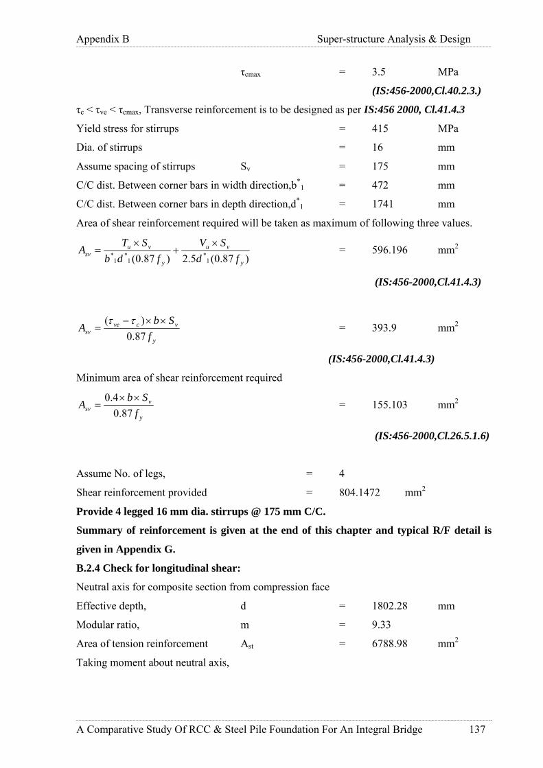
Appendix B Super-structure Analysis & Design
A Comparative Study Of RCC & Steel Pile Foundation For An Integral Bridge 137
τcmax = 3.5 MPa
(IS:456-2000,Cl.40.2.3.)
τc < τve < τcmax, Transverse reinforcement is to be designed as per IS:456 2000, Cl.41.4.3
Yield stress for stirrups = 415 MPa
Dia. of stirrups = 16 mm
Assume spacing of stirrups Sv = 175 mm
C/C dist. Between corner bars in width direction,b*1 = 472 mm
C/C dist. Between corner bars in depth direction,d*1 = 1741 mm
Area of shear reinforcement required will be taken as maximum of following three values.
)87.0(5.2)87.0( 1*
1*
1*
y
vu
y
vusv fd
SVfdb
STA
×+
×= = 596.196 mm2
(IS:456-2000,Cl.41.4.3)
y
vcvesv f
SbA
87.0)( ××−
=ττ
= 393.9 mm2
(IS:456-2000,Cl.41.4.3)
Minimum area of shear reinforcement required
y
vsv f
SbA
87.04.0 ××
= = 155.103 mm2
(IS:456-2000,Cl.26.5.1.6)
Assume No. of legs, = 4
Shear reinforcement provided = 804.1472 mm2
Provide 4 legged 16 mm dia. stirrups @ 175 mm C/C.
Summary of reinforcement is given at the end of this chapter and typical R/F detail is
given in Appendix G.
B.2.4 Check for longitudinal shear:
Neutral axis for composite section from compression face
Effective depth, d = 1802.28 mm
Modular ratio, m = 9.33
Area of tension reinforcement Ast = 6788.98 mm2
Taking moment about neutral axis,

Appendix B Super-structure Analysis & Design
A Comparative Study Of RCC & Steel Pile Foundation For An Integral Bridge 138
)(2
2
xdmAbxst −=
Solving this equation,
Depth of neutral axis, x = 460.95 mm
Area of concrete up to N.A. = 368763.51 mm2
M.I. of concrete area about N.A. = 26118160988 mm4
Transformed area of steel = 63363.829 mm2
M.I. of steel area about N.A. = 114001451969 mm4
Net M.I. about N.A. = 140119612958 mm4
As per IRC: 22-1986 Cl.608.2.2,
IYAV
V cL
..=
Where VL = The longitudinal shear per unit length at the interface in the section
under consideration
V = Vertical shear due to dead load and live load including impact
acting on the section
Ac = Transformed compressive are of concrete above N.A.
Y = Distance from the neutral axis to the centre of area under
consideration,
I = Moment of inertia of whole composite section about N.A.
Vertical shear, V = 1047 KN
Longitudinal shear VL = 635.07 KN
Dia. of stirrups = 16 mm
No. of legs = 4
Spacing = 175 mm
Area of one stirrup = 840.247 mm2
Yield stress of steel = 230 MPa
Shear resistance of one stirrup = 184.97 KN
No. of stirrups in 1m length = 5.71
Total shear resistance = 1057.01 KN
> 635.07 KN
OK.
Provide 4 legged 16 mm dia. stirrups @ 175 mm C/C.

Appendix B Super-structure Analysis & Design
A Comparative Study Of RCC & Steel Pile Foundation For An Integral Bridge 139
B.2.5 Check For Precast Beam:
Precast beam is checked for (self weight of beam + load due to in situ concrete + deck slab +
load from L-girder) including construction live load of 20 KN at the centre of beam.
Self weight of beam = 23.8 KN/m
Load due to in situ concrete 1.005*25*2 = 50.25 KN/m
Total UDL acting on beam = 74.05 KN/m
Load from precast longitudinal girder = 91.25 KN
Load from deck slab over girder 2 to 5 = 0.28*2.275*25*10
= 159.25 KN
Load from deck slab over girder 1 & 8 = 0.28*1.9375*25*10
= 135.625 KN
Load from deck slab over girder 6 & 7 = 0.28*1.75*25*10
= 122.5 KN
Total concentrated load from girder 2 to 5 = 253.75 KN
Total concentrated load from girder 1 & 8 = 245.375 KN
Total concentrated load from girder 6 & 7 = 236 KN
Construction live load at the centre of beam = 20 KN
Max hogging moment = 1536.2 KNm
Design hogging moment Mu = 1843.44 KNm
Hogging reinforcement:-
Dia. of bars provided 1 = 32 mm
No. of bars provided 1 = 8
Clear cover = 25 mm
Grade of concrete fck = 30 M
Grade of steel fy = 500 Fe
Ast provided = 6433.982 mm2
Width of section b = 800 mm
Depth of section D = 900 mm
Effective depth d = 843 mm
Xulim = 387.78 mm
Xuactual = 323.93 mm
< Xulim – Under reinforced.
Moment of resistance MR = 1978.59 KNm
> 1843.44 KNm

Appendix B Super-structure Analysis & Design
A Comparative Study Of RCC & Steel Pile Foundation For An Integral Bridge 140
OK.
Provide 8 bars of 32 mm dia.
Max sagging moment = 549.847 KNm
Design sagging moment Mu = 659.164 KNm
Dia. of bars provided = 32 mm
No.of bars provided = 6
Grade of concrete fck = 30 M
Grade of steel fy = 500 Fe
Ast provided = 4825.486 mm2
Dia. of stirrups = 16 mm
Width of section b = 800 mm
Depth of section D = 900 mm
Effective depth d = 818 mm
Xulim = 387.78 mm
Xuactual = 242.949 mm
> Xulim – Under reinforced.
Moment of resistance MR = 1555.34 KNm
> 659.164 KNm
OK.
Max. shear = 952.34 KN
Design shear Vu = 1142.808 KN
Grade of steel fy = 415 MPa
Effective depth d = 843 mm
Width of section B = 800 mm
Nominal shear stress τve = 1.693 MPa
Percentage of reinforcement Pt = 0.954
Shear strength of concrete τc = 0.644 MPa
Permissible shear stress τcmax = 3.5 MPa
in concrete
τc < τve < τcmax, Transverse reinforcement is to be designed.
Net shear force Vus = 707.667 KN
Dia. of stirrups = 16 mm
No. of legs = 4
Area of stirrups provided = 804.247 mm2

Appendix B Super-structure Analysis & Design
A Comparative Study Of RCC & Steel Pile Foundation For An Integral Bridge 141
Spacing provided Sv = 175 mm
Area of shear reinforcement required = 406.885 mm2
dfSV
Ay
vussv 87.0=
Minimum area of shear reinforcement required = 155.103 mm2
y
vsv f
SbA
87.04.0 ××
=
< 804.247 mm2
OK.
B.2.6 Check for handling stresses:
Precast beam is checked for handling stresses during lifting and stacking.
Self weight of section,
[((0.2+0.275)*0.2/2)+(0.4*0.9)+((0.125+0.1)*0.6/2)]*25 = 11.86 KN/m
Max. hogging moment = 1.5*11.86*1.5*1.5/2 = 20.01 KNm
Grade of concrete fck = 15 M
Grade of steel fy = 500 Fe
Width of section b = 400 mm
Depth of section D = 900 mm
Effective depth d = 843 mm
Dia. of bars provided = 32 mm

Appendix B Super-structure Analysis & Design
A Comparative Study Of RCC & Steel Pile Foundation For An Integral Bridge 142
No. of bars provided = 4
Ast provided = 3216.991 mm2
Xulimit = 387.78 mm
Xuactual = 323.933 mm
< Xulim – Under reinforced.
Moment of resistance MR = 798.907 KNm
> 20.01 KNm
OK.
B.2.7 Design of lifting hook:
Lifting weight of precast beam = 88.95 KN
Impact during handling = 1.25
Total tensile force in hook = 111.1875 KN
(Although 2 hooks are provided, it is assumed that total load acts on one hook taking errors
possible during handling into consideration.)
Grade of steel = 500 MPa
Permissible direct tension = 0.55fy
(IS:456-2000,App.B.2.2.)
= 275 MPa
Assume dia. of hook = 25 mm
No. of hooks = 2
C/S area of one hook = 490.9 mm2
Area required = 404.318 mm2
< 490.9 mm2
OK
Development length
Stress in bar σs = 227.2611 MPa
Bond stress τbd = 0.96
(IS:456-2000,Cl.B.2.1.2.)
Ld = Φ σs / 4 τbd = 1479.564 mm
Say 1500 mm
B.2.8 Check for serviceability:
As per IS:456-2000,Annex F Design surface crack width,

Appendix B Super-structure Analysis & Design
A Comparative Study Of RCC & Steel Pile Foundation For An Integral Bridge 143
xhCa
aW
cr
mcrcr
−−
+=
)(21
3min
ε
Where,
acr = distance from point considered to the surface of the nearest
longitudinal bar
Cmin = clear cover to main reinforcement
h = overall depth of the member
x = depth of neutral axis
εm = average steel strain given by,
)(3))((
1 xdAExaxhb
ssm −
−−−= εε
Where,
As = area of tension steel
b = width of the section
a = distance from the compression face to the point at which crack width is being
calculated.
ε1 = strain at level considered ignoring the stiffening of the concrete inthe tension
zone.
Es = Young’s modulus for steel
Check for stage-I loading:
Details of main reinforcement in beam
Service Bending Moment = 549.847 KNm
Tension Reinforcement
No. of bars = 6
Dia. of bars = 32 mm
No. of bars = 4
Dia. of bars = 20 mm
Dia. of stirrups = 16 mm
Clear cover = 50 mm
Depth of beam h = 900 mm
Width of section b = 800 mm
Effective cover d’ = 99.05 mm
Clear cover main reinforcement Cmin = 66 mm

Appendix B Super-structure Analysis & Design
A Comparative Study Of RCC & Steel Pile Foundation For An Integral Bridge 144
Effective depth d = 800.94 mm
Taking moment about neutral axis,
)(2
2
xdmAbxst −=
Solving this equation,
Depth of neutral axis, x = 273.57 mm
Service stress in reinforcement fst = 131.29 MPa
Strain at level considered steel ε1 = 0.0007
Average steel strain εm = 0.00056
Spacing of bars S = 120.37 mm
Design surface crack width Wcr = 0.152 mm
Check for stage-II loading:
Details of main reinforcement in beam
Service Bending Moment = 1491.761 KNm
Tension Reinforcement
No. of bars = 6
Dia. of bars = 32 mm
No. of bars = 4
Dia. of bars = 20 mm
Dia. of stirrups = 16 mm
Clear cover = 50 mm
Depth of beam h = 1905 mm
Width of flange bf = 2000 mm
Depth of flange Df = 1005 mm
Width of web bw = 800 mm
Effective cover d’ = 99.05 mm
Clear cover main reinforcement Cmin = 66 mm
Effective depth d = 1805.94 mm
Taking moment about neutral axis,
)(2
2
xdmAbxst −=
Solving this equation,
Depth of neutral axis, x = 293.05 mm
Service stress in reinforcement fst = 145.12 MPa

Appendix B Super-structure Analysis & Design
A Comparative Study Of RCC & Steel Pile Foundation For An Integral Bridge 145
Strain at level considered steel ε1 = 0.0007
Average steel strain εm = 0.00038
Spacing of bars S = 120.37 mm
Design surface crack width wcr = 0.097 mm
Total crack width = 0.152+0.097
= 0.249 mm
Permissible crack width = 0.004 times clear cover
(IS:4651-1989 part4,Cl.8.3.4)
= 264 mm
B.2.9 Design Of Corbel:
Load transfer through corbel is a temporary phase, until in situ concrete attains its full
strength. Therefore, reaction due to self weight, dead load from longitudinal girder & deck
slab and construction live load acts as the load on the corbel.
Self weight = (0.2+0.275)*0.2/2*9*25
= 10.6875 KN
Reaction from L-girder = 253.75/2
= 126.875 KN
Total reaction = 137.56 KN
Ultimate load = 1.5*137.56
= 206.34 KN
Ultimate moment = 20.634 KN
Width of longitudinal beam / load, a = 400 mm
Dist. Of the load from face of cantilever support a1 = 100 mm
Effective width of slab = 1.2*a1 + a

Appendix B Super-structure Analysis & Design
A Comparative Study Of RCC & Steel Pile Foundation For An Integral Bridge 146
= 520 mm
Clear cover = 25 mm
Grade of concrete fck = 30 M
Grade of steel fy = 415 Fe
Assuming 16 mm dia. bars,
Effective depth d = 242 mm
Here a1/d = 100/242 = 0.4132
< 1
Also s/D = 200/275 = 0.727
> 0.5
Therefore design as a Corbel.
Design shear,
u
uucku Za
ZabXfV
221
136.0+
=
u
uu Z
ZX 22
3
100100
5203036.01034.206+
××××=×∴
Putting Zu = d – 0.42Xu and solving the above equation,
Xu = 92.7 mm
Zu = 203.066 mm
Main steel:
Tension in horizontal steel Tu = Vu * a1 / Zu
= 101.612 KN
Stress in steel fst = 0.87* fy
= 361.05 MPa
Area of reinforcement required Ast = 101.612*1000/361.05
= 281.43 mm2
Minimum reinforcement required = 0.004*520*242
= 503.36 mm2
Provide 3 bars of 16 mm dia.
Area of steel provided = 603.1104 mm2
> 503.36 mm2
Shear design:
For Pt = 0.479 and M30, ucτ = 1.05 * 0.489
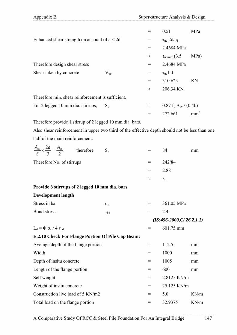
Appendix B Super-structure Analysis & Design
A Comparative Study Of RCC & Steel Pile Foundation For An Integral Bridge 147
= 0.51 MPa
Enhanced shear strength on account of a < 2d = τuc 2d/a1
= 2.4684 MPa
< τucmax (3.5 MPa)
Therefore design shear stress = 2.4684 MPa
Shear taken by concrete Vuc = τuc bd
= 310.623 KN
> 206.34 KN
Therefore min. shear reinforcement is sufficient.
For 2 legged 10 mm dia. stirrups, Sv = 0.87 fy Asv / (0.4b)
= 272.661 mm2
Therefore provide 1 stirrup of 2 legged 10 mm dia. bars.
Also shear reinforcement in upper two third of the effective depth should not be less than one
half of the main reinforcement.
.23
2 stsv AdS
A=× therefore Sv = 84 mm
Therefore No. of stirrups = 242/84
= 2.88
≈ 3.
Provide 3 stirrups of 2 legged 10 mm dia. bars.
Development length
Stress in bar σs = 361.05 MPa
Bond stress τbd = 2.4
(IS:456-2000,Cl.26.2.1.1)
Ld = Φ σs / 4 τbd = 601.75 mm
E.2.10 Check For Flange Portion Of Pile Cap Beam:
Average depth of the flange portion = 112.5 mm
Width = 1000 mm
Depth of insitu concrete = 1005 mm
Length of the flange portion = 600 mm
Self weight = 2.8125 KN/m
Weight of insitu concrete = 25.125 KN/m
Construction live load of 5 KN/m2 = 5.0 KN/m
Total load on the flange portion = 32.9375 KN/m
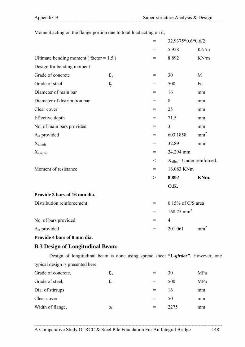
Appendix B Super-structure Analysis & Design
A Comparative Study Of RCC & Steel Pile Foundation For An Integral Bridge 148
Moment acting on the flange portion due to total load acting on it,
= 32.9375*0.6*0.6/2
= 5.928 KN/m
Ultimate bending moment ( factor = 1.5 ) = 8.892 KN/m
Design for bending moment
Grade of concrete fck = 30 M
Grade of steel fy = 500 Fe
Diameter of main bar = 16 mm
Diameter of distribution bar = 8 mm
Clear cover = 25 mm
Effective depth = 71.5 mm
No. of main bars provided = 3 mm
Ast provided = 603.1858 mm2
Xulimit = 32.89 mm
Xuactual = 24.294 mm
< Xulim – Under reinforced.
Moment of resistance = 16.083 KNm
> 8.892 KNm.
O.K.
Provide 3 bars of 16 mm dia.
Distribution reinforcement = 0.15% of C/S area
= 168.75 mm2
No. of bars provided = 4
Ast provided = 201.061 mm2
Provide 4 bars of 8 mm dia.
B.3 Design of Longitudinal Beam: Design of longitudinal beam is done using spread sheet “L-girder”. However, one
typical design is presented here.
Grade of concrete, fck = 30 MPa
Grade of steel, fy = 500 MPa
Dia. of stirrups = 16 mm
Clear cover = 50 mm
Width of flange, bf = 2275 mm

Appendix B Super-structure Analysis & Design
A Comparative Study Of RCC & Steel Pile Foundation For An Integral Bridge 149
Width of web, bw = 400 mm
Overall depth, D = 1005 mm
Depth of flange, Df = 280 mm
B.3.1 Design for sagging moment at mid span:
Equivalent BM, Me = 1531.8 KNm
Dia. of bar 1 Φ1 = 36 mm
Dia. of bar 2 Φ2 = 36 mm
Number of bars 1 = 4
Number of bars 2 = 4
Effective depth, d = 885 mm
Xulim = 408.94 mm
(IS:456-2000,Cl.38.1.)
Ast provided = 8143 mm2
Xuactual = 144.16 mm
Xu < Df – Xu. Neutral axis lies within flange.
Moment of resistance M.R. = 2920 KNm
> 1531.8 KNm
OK.
Provide 4 bars of 36 mm dia and 4 bars of 36 mm dia.
B.3.2 Design for maximum hogging moment at face of pile:
Equivalent BM, Me = 934.12 kNm
Dia. of bar 1 Φ1 = 25 mm
Number of bars 1 = 6
Number of bars 2 = 0
Effective depth, d = 927 mm
Xulim = 426.26 mm
Ast provided = 2945 mm2
Xuactual = 296.56 mm
< Xulim – Under reinforced.
Moment of resistance M.R. = 1027 KNm
> 934.12 KNm
Provide 6 bars of 25 mm dia.
B.3.3 Shear design:
Maximum shear force, Vu = 909 KN

Appendix B Super-structure Analysis & Design
A Comparative Study Of RCC & Steel Pile Foundation For An Integral Bridge 150
Effective depth, d = 927 mm
Width, b = 400 mm
Nominal shear stress,
dbVe
ve ×=τ = 2.45 MPa
Percentage of reinforcement, Pt = 0.79
dbAst
×100
Permissible shear stress in concrete,τc = 0.620 MPa
(IS:456-2000,Cl.40.2.1.)
τcmax = 3.5 MPa
(IS:456-2000,Cl.40.2.3.)
τc < τve < τcmax, Transverse reinforcement is to be designed as per IS:456 2000, Cl.41.4.3
Yield stress for stirrups = 415 MPa
Dia. of stirrups = 12 mm
No. of legs = 2
Dia. of stirrups = 12 mm
No. of legs = 2
Assume spacing of stirrups Sv = 200 mm
Area of shear reinforcement required = 405 mm2
y
vcvesv f
SbA
87.0)( ××−
=ττ
(IS:456-2000,Cl.40.4.a)
Minimum area of shear reinforcement required = 88 mm2
y
vsv f
SbA
87.04.0 ××
= (IS:456-2000,Cl.26.5.1.6)
Shear reinforcement provided = 452 mm2
Provide 2 legged 12 mm dia. and 2 legged 12 mm dia. stirrups @ 200 mm C/C.
Summary of reinforcement is given at the end of this chapter and typical R/F detail is
given in Appendix H.
B.3.4 Check for longitudinal shear:
Neutral axis for composite section from compression face,
Effective depth, d = 926.5 mm
Modular ratio, m = 9.33
Area of tension reinforcement Ast = 2945 mm2

Appendix B Super-structure Analysis & Design
A Comparative Study Of RCC & Steel Pile Foundation For An Integral Bridge 151
Taking moment about neutral axis,
)(2
2
xdmAbxst −=
Solving this equation,
Depth of neutral axis, x = 294.68 mm
Area of concrete up to N.A. = 117874.19 mm2
M.I. of concrete area about N.A. = 3412047111 mm4
Transformed area of steel = 27488.93 mm2
M.I. of steel area about N.A. = 10973296365 mm4
Net M.I. about N.A. = 14385343476 mm4
As per IRC: 22-1986 Cl.608.2.2,
IYAV
V cL
..=
Where VL = The longitudinal shear per unit length at the interface in the
section under consideration
V = Vertical shear due to dead load and live load including impact
acting on the section
Ac = Transformed compressive are of concrete above N.A.
Y = Distance from the neutral axis to the centre of area under
consideration,
I = Moment of inertia of whole composite section about N.A.
Vertical shear, V = 451 KN
Longitudinal shear VL = 544 KN
Dia. of stirrups = 12 mm
No. of legs = 2
Dia. of stirrups = 12 mm
No. of legs = 2
Spacing = 200 mm
Area of stirrups = 452 mm2
Yield stress of steel = 230 MPa
Shear resistance of a pair of stirrups = 104 KN
No. of stirrups in 1m length = 5
Total shear resistance = 520 KN
< 549 KN

Appendix B Super-structure Analysis & Design
A Comparative Study Of RCC & Steel Pile Foundation For An Integral Bridge 152
Therefore increase shear reinforcement.
Provide 2 legged 16 mm dia. stirrups and 2 legged 12 mm dia. stirrups @ 200 mm C/C.
Therefore total shear resistance = 578 KN
> 549 KN.
B.3.5 Check for handling stresses:
Precast beam is checked for handling stresses during lifting and stacking.
Self weight of section
= ((0.4*0.725)+((0.2+0.15)*0.25/2)+ ((0.2+0.15)*0.6/2))*25= 10.97 KN/m
Max. hogging moment = 1.5*10.97*2*2/2 = 32.91 KNm
Grade of concrete fck = 15 MPa
Grade of steel fy = 500 MPa
Width of section b = 400 mm
Depth of section D = 725 mm
Effective depth d = 667 mm
Dia. of main reinforcement = 16 mm
No. of main reinforcement = 2
Ast provided = 402.12 mm2
Xulim = 306.82 mm
Xuactual = 80.98 mm
< Xulim – Under reinforced.
Moment of resistance MR = 110.724 KNm
> 32.91 KNm

Appendix B Super-structure Analysis & Design
A Comparative Study Of RCC & Steel Pile Foundation For An Integral Bridge 153
OK.
B.3.6 Design of lifting hook:
Lifting weight of precast beam = 109.7 KN
Impact during handling = 1.25
Total tensile force in hook = 137.125 KN
(Although 2 hooks are provided, it is assumed that total load acts on one hook taking errors
possible during handling into consideration.)
Grade of steel = 250 MPa
Permissible direct tension = 140 MPa
Assume dia. of hook = 25 mm
No. of hooks = 2
C/S area of the hook = 981.75 mm2
Area required = 979 mm2
< 981.75 mm2
OK
Development length
Stress in bar σs = 139.67 MPa
Bond stress τbd = 0.6
(IS:456-2000,Cl.B.2.1.2.)
Ld = Φ σs / 4 τbd = 1454 mm
Say 1500 mm
B.3.7 Check For Precast Beam:
Precast beam is checked for (self weight of beam + deck slab) including construction live load
of 20 KN placed at centre of beam.
Max sagging moment M = 386.188 KNm
Design sagging moment Mu = 579.282 KNm
Dia. of bars provided = 36 mm
No.of bars provided = 4
Dia. of bars provided = 32 mm
No.of bars provided = 4
Grade of concrete fck = 30 MPa
Grade of steel fy = 500 MPa
Ast provided = 7288 mm2
Dia. of stirrups = 16 mm
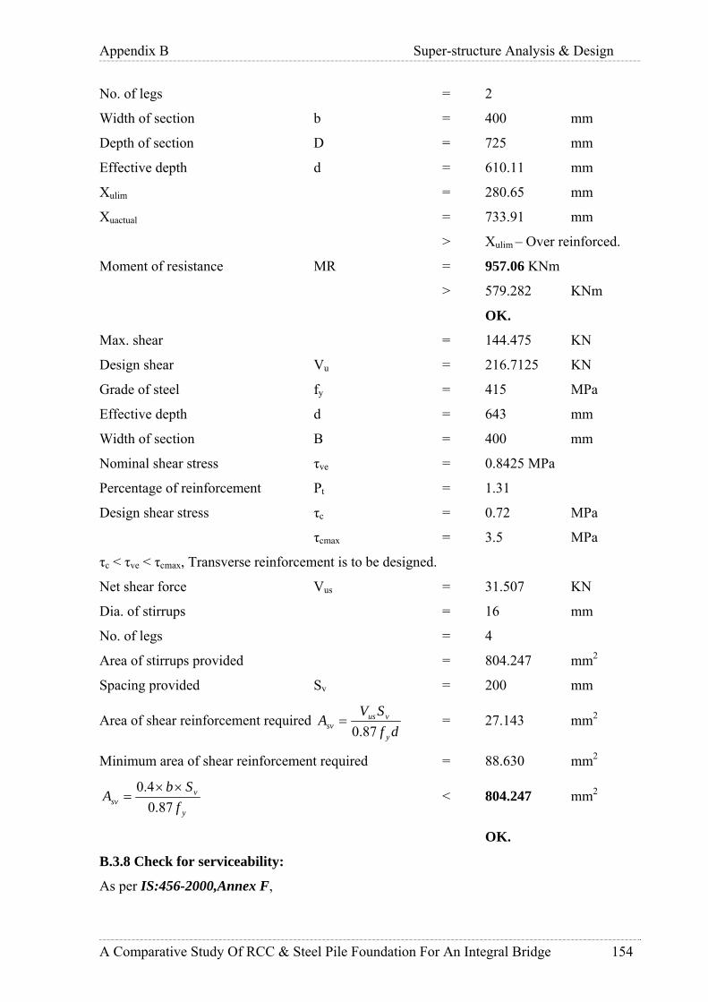
Appendix B Super-structure Analysis & Design
A Comparative Study Of RCC & Steel Pile Foundation For An Integral Bridge 154
No. of legs = 2
Width of section b = 400 mm
Depth of section D = 725 mm
Effective depth d = 610.11 mm
Xulim = 280.65 mm
Xuactual = 733.91 mm
> Xulim – Over reinforced.
Moment of resistance MR = 957.06 KNm
> 579.282 KNm
OK.
Max. shear = 144.475 KN
Design shear Vu = 216.7125 KN
Grade of steel fy = 415 MPa
Effective depth d = 643 mm
Width of section B = 400 mm
Nominal shear stress τve = 0.8425 MPa
Percentage of reinforcement Pt = 1.31
Design shear stress τc = 0.72 MPa
τcmax = 3.5 MPa
τc < τve < τcmax, Transverse reinforcement is to be designed.
Net shear force Vus = 31.507 KN
Dia. of stirrups = 16 mm
No. of legs = 4
Area of stirrups provided = 804.247 mm2
Spacing provided Sv = 200 mm
Area of shear reinforcement required df
SVA
y
vussv 87.0= = 27.143 mm2
Minimum area of shear reinforcement required = 88.630 mm2
y
vsv f
SbA
87.04.0 ××
= < 804.247 mm2
OK.
B.3.8 Check for serviceability:
As per IS:456-2000,Annex F,

Appendix B Super-structure Analysis & Design
A Comparative Study Of RCC & Steel Pile Foundation For An Integral Bridge 155
Design surface crack width,
xhCa
aW
cr
mcrcr
−−
+=
)(21
3min
ε
Where,
acr = distance from point considered to the surface of the nearest
longitudinal bar
Cmin = clear cover to main reinforcement
h = overall depth of the member
x = depth of neutral axis
εm = average steel strain given by,
)(3))((
1 xdAExaxhb
ssm −
−−−= εε
Where,
As = area of tension steel
b = width of the section
a = distance from the compression face to the point at which crack
width is being calculated.
ε1 = strain at level considered ignoring the stiffening of the concrete in
the tension zone.
Es = Young’s modulus for steel
Check for stage-I loading:-
Details of main reinforcement in beam
Service Bending Moment = 386 KNm
Tension Reinforcement
No. of bars = 4
Dia. of bars = 36 mm
No. of bars = 4
Dia. of bars = 36 mm
Dia. of stirrups = 16 mm
Clear cover = 50 mm
Depth of beam h = 725 mm
Width of section b = 400 mm
Effective cover d’ = 120 mm

Appendix B Super-structure Analysis & Design
A Comparative Study Of RCC & Steel Pile Foundation For An Integral Bridge 156
Clear cover main reinforcement Cmin = 66 mm
Effective depth d = 605 mm
Taking moment about neutral axis,
)(2
2
xdmAbxst −=
Solving this equation,
Depth of neutral axis, x = 325.73 mm
Service stress in reinforcement fst = 107.8 MPa
Strain at level considered steel ε1 = 0.00065
Average steel strain εm = 0.0006
Spacing of bars S = 77.33 mm
Radial distance to surface of bar acr = 74.47 mm
Design surface crack width wcr = 0.162 mm
Check for stage-II loading:-
Details of main reinforcement in beam
Service Bending Moment = 612.55 KNm
Tension Reinforcement
No. of bars = 4
Dia. of bars = 36 mm
No. of bars = 4
Dia. of bars = 36 mm
Compression Reinforcement
No. of bars = 0
Dia. of bars = 0 mm
Dia. of stirrups = 16 mm
Clear cover = 50 mm
Depth of beam h = 1005 mm
Width of flange bf = 2275 mm
Depth of flange Df = 280 mm
Width of web bw = 400 mm
Effective cover d’ = 120 mm
Clear cover main reinforcement Cmin = 66 mm
Effective depth d = 885 mm
Taking moment about neutral axis,

Appendix B Super-structure Analysis & Design
A Comparative Study Of RCC & Steel Pile Foundation For An Integral Bridge 157
)(2
2
xdmAbxst −=
Solving this equation,
Depth of neutral axis, x = 212.04 mm
Service stress in reinforcement fst = 97.31 MPa
Strain at level considered steel ε1 = 0.00048
Average steel strain εm = 0.00054
Spacing of bars S = 77.33 mm
Radial distance to surface of bar acr = 74.47 mm
Design surface crack width wcr = 0.102 mm
Total crack width = 0.162+0.102
= 0.264 mm
Permissible crack width = 0.004 times clear cover to main reinforcement
(IS:4651-1989 part4,Cl.8.3.4)
= 0.264 mm
B.3.9 Design Of Haunch:
Dead load of precast planks placed over longitudinal beams acts as load for haunch portion.
Bearing of deck plank = 150 mm
Self weight of the beam = 4.375 KN/m
Assuming 1m wide precast deck plank,
Self weight of plank = 0.28*1.675*25/2 = 5.8625 KN/m
Construction live load = 1.675*2/2 = 1.675 KN/m
Point load acting at 175 mm from edge = 7.5375 KN
Maximum bending moment = 1.455 KNm
Grade concrete fck = 30 MPa
Grade of steel fy = 415 MPa
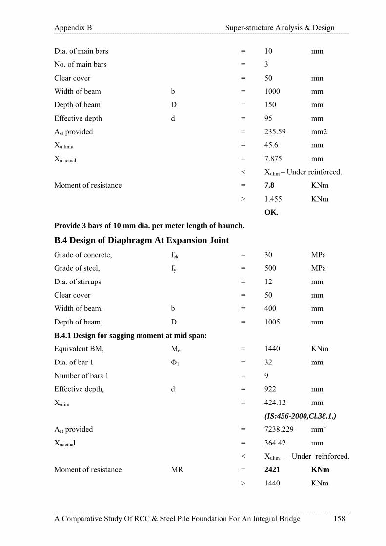
Appendix B Super-structure Analysis & Design
A Comparative Study Of RCC & Steel Pile Foundation For An Integral Bridge 158
Dia. of main bars = 10 mm
No. of main bars = 3
Clear cover = 50 mm
Width of beam b = 1000 mm
Depth of beam D = 150 mm
Effective depth d = 95 mm
Ast provided = 235.59 mm2
Xu limit = 45.6 mm
Xu actual = 7.875 mm
< Xulim – Under reinforced.
Moment of resistance = 7.8 KNm
> 1.455 KNm
OK.
Provide 3 bars of 10 mm dia. per meter length of haunch.
B.4 Design of Diaphragm At Expansion Joint Grade of concrete, fck = 30 MPa
Grade of steel, fy = 500 MPa
Dia. of stirrups = 12 mm
Clear cover = 50 mm
Width of beam, b = 400 mm
Depth of beam, D = 1005 mm
B.4.1 Design for sagging moment at mid span:
Equivalent BM, Me = 1440 KNm
Dia. of bar 1 Φ1 = 32 mm
Number of bars 1 = 9
Effective depth, d = 922 mm
Xulim = 424.12 mm
(IS:456-2000,Cl.38.1.)
Ast provided = 7238.229 mm2
Xuactual = 364.42 mm
< Xulim – Under reinforced.
Moment of resistance MR = 2421 KNm
> 1440 KNm

Appendix B Super-structure Analysis & Design
A Comparative Study Of RCC & Steel Pile Foundation For An Integral Bridge 159
OK
Provide 9 bars of 32 mm dia.
B.4.2 Design for maximum hogging moment at face of pile:
Equivalent BM, Me = 1514 KNm
Dia. of bar 1 Φ1 = 32 mm
Number of bars 1 = 4
Number of bars 2 = 0
Effective depth, d = 922 mm
Xulim = 424.12 mm
Ast provided = 4825.5 mm2
Xuactual = 242.94 mm
< Xulim – Under reinforced.
Moment of resistance MR = 1721 KNm
> 1514 KNm
Provide 4 bars of 32 mm dia.
B.4.3 Shear design:
Maximum shear force, Vu = 1003 KN
Corresponding torsion, Tu = 101 KN
Design equivalent shear force, Ve = 1203 KN
Effective depth, d = 922 mm
Width, b = 800 mm
Nominal shear stress, db
Veve ×=τ = 1.63 MPa
Percentage of reinforcement, Pt = 0.65
Permissible shear stress in concrete,τc = 0.55 MPa
(IS:456-2000,Cl.40.2.1.)
τcmax = 3.5 MPa
(IS:456-2000,Cl.40.2.3.)
τc < τve < τcmax, Transverse reinforcement is to be designed as per IS:456 2000, Cl.41.4.3
Yield stress for stirrups = 415 MPa
Dia. of stirrups = 12 mm
Assume spacing of stirrups Sv = 175 mm
Area of shear reinforcement required = 418.77 mm2

Appendix B Super-structure Analysis & Design
A Comparative Study Of RCC & Steel Pile Foundation For An Integral Bridge 160
y
vcvesv f
SbA
87.0)( ××−
=ττ
Minimum area of shear reinforcement required = 155.103 mm2
y
vsv f
SbA
87.04.0 ××
= (IS:456-2000,Cl.26.5.1.6)
Shear reinforcement provided = 452.39 mm2
Provide 4 legged 12 mm dia. stirrups @ 175 mm C/C.
B.4.4 Check for serviceability:
As per IS:456-2000,Annex F Design surface crack width,
xhCa
aW
cr
mcrcr
−−
+=
)(21
3min
ε
Where,
acr = distance from point considered to the surface of the nearest
longitudinal bar
Cmin = clear cover to main reinforcement
h = overall depth of the member
x = depth of neutral axis
εm = average steel strain given by,
)(3))((
1 xdAExaxhb
ssm −
−−−= εε
Where,
As = area of tension steel
b = width of the section
a = distance from the compression face to the point at which crack width is being
calculated.
ε1 = strain at level considered ignoring the stiffening of the concrete in the tension
zone.
Es = Young’s modulus for steel
Details of main reinforcement in beam
Service Bending Moment = 1164 KNm
Tension Reinforcement
No. of bars = 9
Dia. of bars = 32 mm

Appendix B Super-structure Analysis & Design
A Comparative Study Of RCC & Steel Pile Foundation For An Integral Bridge 161
Dia. of stirrups = 12 mm
Clear cover = 50 mm
Depth of beam h = 1000 mm
Width of section b = 800 mm
Effective cover d’ = 78 mm
Clear cover main reinforcement Cmin = 62 mm
Effective depth d = 922 mm
Taking moment about neutral axis,
)(2
2
xdmAbxst −=
Solving this equation,
Depth of neutral axis, x = 319.5 mm
Service stress in reinforcement fst = 197.163 MPa
Strain at level considered steel ε1 = 0.0001
Average steel strain εm = 0.000092
Spacing of bars S = 80.5 mm
Radial distance to surface of bar acr = 71.772 mm
Design surface crack width wcr = 0.193 mm
Permissible crack width = 0.004 times clear cover to main reinforcement
(IS:4651-1989 part4,Cl.8.3.4)
= 0.248 mm
Typical R/F detail is given in Appendix I.
B.5 Design of Deck Slab: Two typical designs are done for the slab covering road width (DP1) and slab covering
conveyor system (DP2).
Grade concrete fck = 30 MPa
Grade of steel fy = 500 MPa
Dia. of main bars = 16 mm
Dia. of main bars = 12 mm
Clear cover = 50 mm
Width of section b = 1000 mm
Depth of section D = 280 mm
Effective depth d = 210 mm
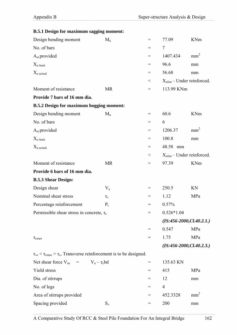
Appendix B Super-structure Analysis & Design
A Comparative Study Of RCC & Steel Pile Foundation For An Integral Bridge 162
B.5.1 Design for maximum sagging moment:
Design bending moment Mu = 77.09 KNm
No. of bars = 7
Ast provided = 1407.434 mm2
Xu limit = 96.6 mm
Xu actual = 56.68 mm
< Xulim – Under reinforced.
Moment of resistance MR = 113.99 KNm
Provide 7 bars of 16 mm dia.
B.5.2 Design for maximum hogging moment:
Design bending moment Mu = 60.6 KNm
No. of bars = 6
Ast provided = 1206.37 mm2
Xu limit = 100.8 mm
Xu actual = 48.58 mm
< Xulim – Under reinforced.
Moment of resistance MR = 97.39 KNm
Provide 6 bars of 16 mm dia.
B.5.3 Shear Design:
Design shear Vu = 250.5 KN
Nominal shear stress τv = 1.12 MPa
Percentage reinforcement Pt = 0.57%
Permissible shear stress in concrete, τc = 0.526*1.04
(IS:456-2000,Cl.40.2.1.)
= 0.547 MPa
τcmax = 1.75 MPa
(IS:456-2000,Cl.40.2.3.)
τve < τcmax > τc, Transverse reinforcement is to be designed.
Net shear force Vus = Vu – τcbd = 135.63 KN
Yield stress = 415 MPa
Dia. of stirrups = 12 mm
No. of legs = 4
Area of stirrups provided = 452.3328 mm2
Spacing provided Sv = 200 mm

Appendix B Super-structure Analysis & Design
A Comparative Study Of RCC & Steel Pile Foundation For An Integral Bridge 163
Area of shear reinforcement required df
SVA
y
vussv 87.0= = 357.76 mm2
Minimum area of shear reinforcement required = 221.57 mm2
y
vsv f
SbA
87.04.0 ××
= < 452.33 mm2
OK.
Provide 4 legged 12 mm dia. stirrups @ 200 mm C/C.
B.5.4 Check for longitudinal shear:
Modular ratio m = 9.333
Area of tension reinforcement = 1206.37 mm2
Taking moment about neutral axis,
)(2
2
xdmAbxst −=
Solving this equation,
Depth of neutral axis, x = 58.42 mm
Area of concrete up to N.A. = 58423 mm2
M.I. of concrete area about N.A. = 66473301 mm4
Transformed area of steel = 11259.46 mm2
M.I. of steel area about N.A. = 258690294.8 mm4
Net M.I. about N.A. = 325163595 mm4
As per IRC: 22-1986 Cl.608.2.2,
IYAV
V cL
..=
Where VL = The longitudinal shear per unit length at the interface in the
section under consideration
V = Vertical shear due to dead load and live load including impact
acting on the section
Ac = Transformed compressive are of concrete above N.A.
Y = Distance from the neutral axis to the centre of area under
consideration,
I = Moment of inertia of whole composite section about N.A.
Vertical shear, V = 157 KN

Appendix B Super-structure Analysis & Design
A Comparative Study Of RCC & Steel Pile Foundation For An Integral Bridge 164
Longitudinal shear VL = 824 KN
Dia. of stirrups = 12 mm
No. of legs = 4
Spacing = 200 mm
Area of one stirrup = 113.0976 mm2
Yield stress of steel = 230 MPa
Shear resistance of 12 mm bar = 104.04 KN
No. of stirrups in 1m length = 5
Total shear resistance = 520.24 KN
< 824 KN
Therefore increase shear reinforcement.
Provide 6 legged 12 mm dia. Stirrups @ 200 mm C/C.
Therefore total shear resistance = 918 KN
> 824 KN.
B.5.5 Distribution steel:
Percentage reinforcement required Pt = 0.12%
Ast required = 336 mm2
Dia. of bars = 10 mm
No. of bars = 5
B.5.6 Summary of reinforcement:
Deck plank DP1
Sagging moment = 7Nos-16mm# per meter width
Hogging moment = 6 Nos-16mm# per meter width
Shear reinforcement = 6legged 12mm# @ 170mm C/C.
Deck plank DP2
Sagging moment = 5 bars of 10mm# per meter width
Hogging moment = 5 bars of 10mm# per meter width
Shear reinforcement = 3legged 12 mm# @ 200mm C/C.
Typical R/F detail is given in Appendix J.
B.5.7 Check For Precast:
Precast deck is checked for (self weight of deck plank + insitu deck slab) including
construction live load of 2 KN/m2.
Total UDL coming on precast section = 6.28+5.44+(2*1) = 13.72 KN/m
Max sagging moment = 4.811 KNm
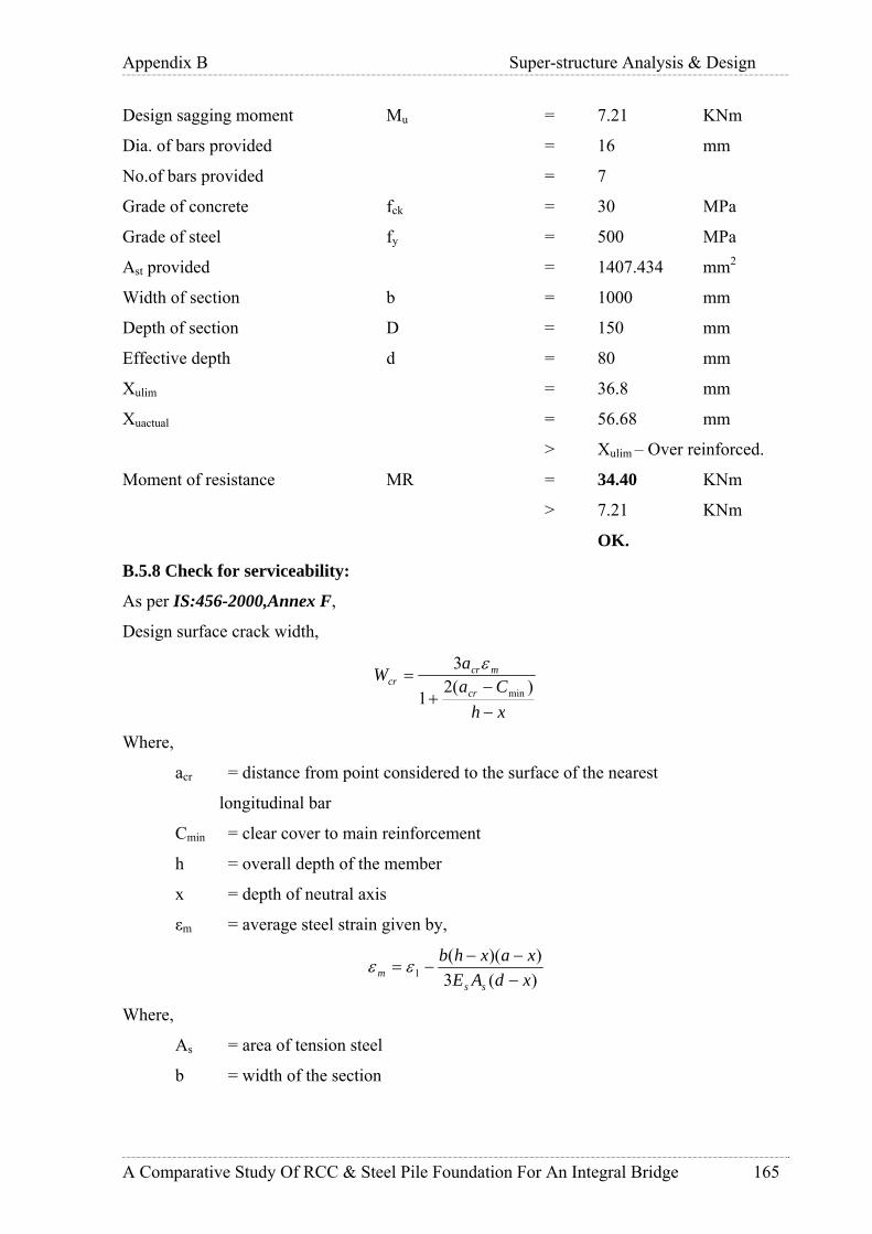
Appendix B Super-structure Analysis & Design
A Comparative Study Of RCC & Steel Pile Foundation For An Integral Bridge 165
Design sagging moment Mu = 7.21 KNm
Dia. of bars provided = 16 mm
No.of bars provided = 7
Grade of concrete fck = 30 MPa
Grade of steel fy = 500 MPa
Ast provided = 1407.434 mm2
Width of section b = 1000 mm
Depth of section D = 150 mm
Effective depth d = 80 mm
Xulim = 36.8 mm
Xuactual = 56.68 mm
> Xulim – Over reinforced.
Moment of resistance MR = 34.40 KNm
> 7.21 KNm
OK.
B.5.8 Check for serviceability:
As per IS:456-2000,Annex F,
Design surface crack width,
xhCa
aW
cr
mcrcr
−−
+=
)(21
3min
ε
Where,
acr = distance from point considered to the surface of the nearest
longitudinal bar
Cmin = clear cover to main reinforcement
h = overall depth of the member
x = depth of neutral axis
εm = average steel strain given by,
)(3))((
1 xdAExaxhb
ssm −
−−−= εε
Where,
As = area of tension steel
b = width of the section

Appendix B Super-structure Analysis & Design
A Comparative Study Of RCC & Steel Pile Foundation For An Integral Bridge 166
a = distance from the compression face to the point at which crack width is
being calculated.
ε1 = strain at level considered ignoring the stiffening of the concrete in the tension
zone.
Es = Young’s modulus for steel
Check for stage-I loading:-
Details of main reinforcement in beam
Service Bending Moment = 5.234 KNm
Tension Reinforcement
No. of bars = 7
Dia. of bars = 16 mm
Dia. of stirrups = 12 mm
Clear cover = 50 mm
Depth of beam h = 150 mm
Width of section b = 1000 mm
Effective cover d’ = 70 mm
Clear cover main reinforcement Cmin = 62 mm
Effective depth d = 70 mm
Taking moment about neutral axis,
)(2
2
xdmAbxst −=
Solving this equation,
Depth of neutral axis, x = 34.55 mm
Service stress in reinforcement fst = 55.4 MPa
Strain at level considered steel ε1 = 0.00067
Average steel strain εm = 0.00033
Spacing of bars S = 135 mm
Design surface crack width wcr = 0.061 mm
Check for stage-II loading:-
Details of main reinforcement in beam
Service Bending Moment = 46 KNm
Tension Reinforcement
No. of bars = 7
Dia. of bars = 16 mm

Appendix B Super-structure Analysis & Design
A Comparative Study Of RCC & Steel Pile Foundation For An Integral Bridge 167
Dia. of stirrups = 12 mm
Clear cover = 50 mm
Depth of beam h = 280 mm
Width of beam b = 1000 mm
Effective cover d’ = 70 mm
Clear cover main reinforcement Cmin = 62 mm
Effective depth d = 210 mm
Taking moment about neutral axis,
)(2
2
xdmAbxst −=
Solving this equation,
Depth of neutral axis, x = 62.29 mm
Service stress in reinforcement fst = 172.21 MPa
Strain at level considered steel ε1 = 0.0012
Average steel strain εm = 0.00085
Spacing of bars S = 135 mm
Design surface crack width wcr = 0.182 mm
Total crack width = 0.182+0.061
= 0.243 mm
Permissible crack width = 0.004 times clear cover to main reinforcement
(IS:4651-1989 part4,Cl.8.3.4)
= 0.248 mm

Me Ve Vu Tu Me Me fck fy fy bw bf df D c 1 2 s1 s2 N1 N2 Astpro MR n1 n2 Svreqd Svpro Wcr Wcr Wcr
KNm KN KN KNm KNm KNm KN MPa MPa MPa mm mm mm mm mm mm mm mm mm mm2 KNm mm mm mm mm mm mm
800
800
800
800415
415
415
415 32
32
1005 1905 50
1005 1905 50 25 2003612 41216 2066
Description
Sagging - midspan
Hogging at faceof support +shear at 'd'
distance fromface of support
Sagging - faceof support
Sagging - 2.25mfrom support
4
0 4825.49 0
0
0.152 0.097
0.001 0.08
175
3740
6 4 6788.98 4898
4825.49
6 4641
3740
6 0
4
0
25 1216
163232 12
2032
2000
2000
2000
2000
2000
500
500
500
500
500
30
30
30
30
30
606.5
606.53357
1955
2144
1005 1905 50 12
1005 1905 50
Spac
ing
Prov
ided
Cra
ck W
idth
stag
e-I
Cra
ck W
idth
stag
e-II
Tot
al C
rack
Wid
th
Allo
wab
le C
rack
Wid
th
Ulti
mat
e Sh
ear
Ulti
mat
e T
orsi
on
Gra
de o
f ste
elfo
r st
irru
ps
Eff
ectiv
e W
idth
of F
lang
e
Wid
th o
f Web
415 1905 50
Dia
. Of B
ar
321005 20800
Equ
ival
ent B
.M
Equ
ival
ent S
hear
Hogging &shear - 2.25mfrom support
1417
4335
1932
942.1
4708
3168
Bar
Gra
de o
fco
ncre
teG
rade
of s
teel
for
mai
n R
/F
Dep
th o
f Fla
nge
Ove
rall
Dep
th
Cle
ar c
over
Dia
. Of B
ar
12
Design Forces
0.264
0.264
0.264
0.264
0.264
0.249
0.081
198
PILECAP DESIGN SUMMARY
Spac
ing
Req
uire
d
Serv
icea
bilit
ym
omen
t sta
ge-I
Serv
icea
bilit
ym
omen
t sta
ge-I
ISh
ear
for
Lon
g.Sh
ear
chec
k
549.8 1492
Dia
.of S
tirru
ps
16
16
No.
of l
egs
6
6082.12
4825.49
No.
of l
egs
Are
a O
fR
einf
orce
men
tPr
ovid
ed
Mom
ent O
fR
esis
tanc
e
Dia
.of S
tirru
ps
Bar
132.7 1252
1047
564
Physical Data Crack width checkReinforcement Shear Reinforcement
Appendix E Super-structure Analysis & Design
A Comparative Study Of RCC & Steel Pile Foundation For An Integral Bridge 168

Me Vu Me Me fck fy fy bw bf df D c 1 2 s1 s2 N1 N2 Astpro MR n1 n2 Svreqd Svpro Wcr Wcr Wcr
KNm KN KNm KNm KN MPa MPa MPa mm mm mm mm mm mm mm mm mm mm2 KNm mm mm mm mm mm mm
415
415
415
415
415
415
415
415
415
415
415
415
0.245
0.226
0.249
0.225
0.032
0.036
Cra
ck W
idth
stag
e-II
0.097
0.122
0.064
0.057
200
181
360
282.74
Design Forces
Serv
icea
bilit
ym
omen
t sta
ge-
II
612.55
603
4
4
4
6
3
3
403.5
61.85 226.4
651.67
Sagging - 3mfrom support
36
36
25
32
25
501938 280 1005
MomentLocation
Sagging - midspan
Hogging at faceof support
Sagging - 3mfrom support
2 300 250*
2 300 250*
4825.486316 1804
553.61
2945.243113
6433.981755
2262
2920
2
2
4 8143.008158
2336
6107.256119
1472.621556
1027
16
0
0
16
4
44
12
12
12
120
280 1005 50 160
16 12280 1005 50
280 1005 50
2275
2275
2275
2275 280 1005 50
400
400
400
400
500
500
500
500
30
30
30
30
577.5
909
102.83
1531.8
1344.2
934.12
Dia
.of S
tirru
ps
Mom
ent O
fR
esis
tanc
e
Bar
No.
of l
egs
Tot
al C
rack
Wid
th
Physical Data Reinforcement Shear Reinforcement
No.
of l
egs
Spac
ing
Req
uire
d
Spac
ing
Prov
ided
Cra
ck W
idth
stag
e-I
Allo
wab
leC
rack
Wid
th
Dia
. Of B
ar
16
Dia
. Of B
ar
36
Dia
.of S
tirru
ps
12
386 30 500
Are
a O
fR
einf
orce
men
tPr
ovid
ed
Bar
Wid
th o
f Web
Eff
ectiv
eW
idth
of
Flan
geD
epth
of
Flan
ge
Ove
rall
Dep
th
Cle
ar c
over
790.5
527.1
344.8
726.41
Bea
mG
irde
r 2
to 4
Serv
icea
bilit
ym
omen
t sta
ge-
I
386.19
312
Ulti
mat
e Sh
ear
Hogging - 3mfrom support
Crack width check
0.159
0.142
Equ
ival
ent
B.M
Gra
de o
fco
ncre
te
Gra
de o
f ste
elfo
r m
ain
R/F
36
Gra
de o
f ste
elfo
r st
irru
ps
Shea
r fo
rL
ong.
She
arch
eck
0.264
0.264
0.264
0.264
0.256
0.264
Gir
der
1 &
5
Sagging - midspan 1050
Hogging - 3mfrom support
Sagging - 3mfrom support
106.55
Hogging at faceof support 778.87
400 1938 280 1005 50 32 1632 0.185 0.264
923.39 312 30 500 400 0.168 0.264
30 500 400180 1938 280 01005 50 25 16 612 2945.243113 1027 2 3000 250* 0.264
30 500 400 1938 280 01005 50 25 16 12 0.264
Gir
der
6 to
8
Sagging - midspan 386 30 500 400
553.61
1005 50
3002 3001472.621556
2 4825.48631612
L-GIRDER DESIGN SUMMARY
32 161750 280 1794 0.213 0.264
312 30 500 400 1750 280 1005 50 32 1632 0 3216.990877412 1248 0.19 0.264
Hogging at faceof support 30 500 400 1750 280 1005 50 20 160 0 1884.9555926 696.37 0 300 3002 0.264
Hogging - 3mfrom support 30 500 400 1750 280 1005 364.5350 20 160 0.2640 300 3002
32
32
32
32
12
12
2
0
0
03 942.4777961
451
305
69
108
112
Appendix E Super-structure Analysis & Design
A Comparative Study Of RCC & Steel Pile Foundation For An Integral Bridge 169
APPENDIX ‐ C
GENERAL ARRNGMENT DRAWING


APPENDIX ‐ D
CONSTRUCTION SEQUENCE DRAWING


APPENDIX ‐ E
RCC PILE DETAIL DRAWING


APPENDIX ‐ F
STEEL PILE DETAIL DRAWING


APPENDIX ‐ G
PILE CAP BEAM REINFORCEMENT DETAIL DRAWING


APPENDIX ‐ H
LONGITUDINAL BEAM REINFORCEMENT DETAIL DRAWING


APPENDIX ‐ I
DIAPHRAGM REINFORCEMENT DETAIL DRAWING


APPENDIX ‐ J
DECK SLAB REINFORCEMENT DETAIL DRAWING


National Conference on Recent Advancements in Civil Engineering & Infrastructural Developments (RACE-InD 2011) 21-22 December, 2011 Department of Civil Engineering, Jaypee University of Engineering & Technology, Guna, MP, India
A Comparative Study Of RCC & Steel Pile Foundation For An Integral Bridge
Viral B. Panchal M.E.(CASAD) Student, Applied Mechanics Department, L.D.College Of Engineering, Ahmedabad, Gujarat, India.
C.S.Sanghvi Associate Professor, Applied Mechanics Department, L.D.College Of Engineering, Ahmedabad, Gujarat,India.
Keywords: Integral bridge, RCC bored cast in situ piles, driven steel piles, bearing, marine, pile bearing capacity, pile fixity, soil spring stiffness, seismic, deflection.
ABSTRACT: The increase in demand for complex roadway alignments, advances in construction technology and availability of computing power for bridges design, are some of the factors for developments in bridge engineering. Concept of “Integral Bridges” is one of these developments. Due to ease & economy in construction and maintenance, it is also getting popular in India. Integral bridge concept is also widely adopted in marine structures where many times foundations are flexible like pile foundation. Main reasons for increasing popularity of integral concept in marine structures are efforts of minimizing use of bearings and to resist large lateral forces. Integral bridge requires flexible foundation to accommodate thermal stresses and stresses produced from lateral forces like waves, current, wind, seismic etc. As pile foundation is a flexible foundation as compared to piers or caissons and because of ease of construction it is generally adopted in marine structures. However there can be variations in pile foundations for integral bridges like bored cast in situ RCC piles, driven precast piles, driven precast prestress piles, driven steel piles etc. This study is based on the comparison of structural response of a marine integral bridge with two different pile types i.e. RCC bored cast in situ piles and driven steel piles. Structural configuration, site specific data and load data for RCC pile option is obtained for an existing marine approach bridge at Dahej, India. Structural as well as geotechnical design of bored cast in situ RCC piles is done for the available data. Foundation is then changed to driven steel piles. 4 different diameters are tried to arrive at optimum steel pile diameter. Structural response of this optimum diameter steel piled structure is compared with RCC piled structure.
1 Introduction Integral Bridge Concept: Integral bridges are bridges where the superstructure is continuous and connected monolithically with the substructure with a moment-resisting connection. As an effect we obtain a structure acting as one unit. Integral bridges accommodate superstructure movements without conventional expansion joints. With the superstructure rigidly connected to the substructure and with flexible substructure piling, the superstructure is permitted to expand and contract. Such bridges are the answer for small and medium length bridges where bearings and expansion joints can be either eliminated altogether or reduced to a minimum. By incorporation of intermediate expansion joints, the integral bridge concept can be extended to long bridges and viaducts too. Integral bridges are designed to provide resistance to thermal movements, breaking forces, seismic forces and winds by the stiffness of the soil abutting the end supports and the intermediate supports. A typical three span integral abutment bridge is shown in Fig. 1. Provision of joints and bearings induces decrease in redundancy and difficulties in providing adequate ductility for resisting earthquake effects, leading to larger earthquake design forces. Possibilities of dislodgement of superstructure during accidental loads, especially those due to earthquakes, is a clear danger requiring expensive and clumsy attachments.

National Conference on Recent Advancements in Civil Engineering & Infrastructural Developments (RACE-InD 2011) 21-22 December, 2011 Department of Civil Engineering, Jaypee University of Engineering & Technology, Guna, MP, India
Surajbari new bridge superstructure shifted in the transverse direction
Bridge between Surajbari & Bhachau – Violent shaking has resulted in pier head being damaged due to pounding of deck Application of Integral bridge concept is also widely seen in pile supported marine structures. In such water front structures, it is very difficult and costly to replace bearings. Also due to the equipments on the deck level, movement of the deck is limited in horizontal directions. So, less numbers of joints are required to reduce these longitudinal and lateral movements. Also many a times, marine structures are supported on piles or sheet piles which are easier to construct as compared to other deep foundations in ocean water with aggressive environmental conditions. And super structure is rigidly connected to piles. So lateral movements induced due to temperature produced stresses and environmental loadings such as waves, current and wind are effectively sustained by piles and transferred to the ground. As piles are slender flexible members, it can sustain more bending and deflections. Piles used in marine structures are subjected to lateral loads from the impact of berthing ships and from waves. Combinations of vertical and horizontal loads are carried where piles are used to support retaining walls, bridge piers and abutments, and machinery foundations. Bored cast in situ RCC piles are conventional piling option for marine structures especially in India. But now with the advancement in construction methods, construction equipments and increase in availability of technical-financial resoures, use of driven steel piles is becoming popular, Steel piles are costly in terms of material and construction cost. But steel piles are advantageous in terms of saving in construction time as construction of steel pile is very fast as compared to bored cast in situ piles. However, use of driven steel piles over bored cast in situ RCC piles is dependent upon loading condition, serviceability criteria (deflection as steel piles deflect more) and site condition. Therefore the decision to use steel piles over RCC piles defers from project to project. Comparison of structural behavior of a marine approach bridge with these two pile types is studied. Data related to structural configuration, site specific data such as soil data, ground levels, environmental loadings etc. are obtained for an existing approach bridge at Dahej, India. Existing structure is having RCC pile. Existing structure is checked for the use of driven steel piles. Change in structural behavior of super structure elements due to change in sub structure is also studied. Description of structure used for analysis and design: Approach bridge carries 7.5 m wide carriageway with provision for steel trestle for conveyor galleries. The

National Conference on Recent Advancements in Civil Engineering & Infrastructural Developments (RACE-InD 2011) 21-22 December, 2011 Department of Civil Engineering, Jaypee University of Engineering & Technology, Guna, MP, India
structure consists of 1.0m dia. bored cast in situ piles with pilecap beams spanning across pile bents. Entire 1168m long approach is divided into 7 units each unit consisting of approximately 125 m length. Each unit consists of approximately 13 pile bents at a spacing of 12m. Each unit is separated from adjacent unit by expansion gaps. GA drawing is attached at the end of paper. Sea bed level is (+)3.15m CD and 2m scour level is considered in addition. Top of deck is (+)15.00m CD. Deflection at top of deck in operating condition is limited to 50mm suit proper functioning of material handling system installed over deck.
2 Analysis & Design Loads and Load combinations: Following loads are considered in analysis: 1.0 Dead load of the structure 2.0 Construction, erection and handling loads 3.0 Vehicular and other possible live load 4.0 Impact load of moving live load (not considered for pile design, only for super structure design) 5.0 Braking force 6.0 Wind load (operating and extreme) 7.0 Seismic force 8.0 Wave force (operating and extreme) 9.0 Water current force (operating and extreme) 10.0 Buoyancy 11.0 Thermal effect 12.0 Secondary effects (shrinkage etc.) Load combinations are considered as per IS 456:2000 and IS 4651(Part4):1989.
The 3-D modeling and analysis of the structure is carried out with Staadpro 2007 package. Beams and slabs are modelled as beam elements. Piles are modelled as a beam elements and soil is modelled as a spring supports with soil stiffness.
P Delta analysis is carried out to consider slenderness effect and to achieve economical design. Structural design of RCC elements is done for Limit state of collapse and checked for limit state of serviceability as per IS:456-2000. The geotechnical design of bored cast in situ RCC piles is also carried out as per the IS:2911 (part 1/sec 2)-1979. Structural as well as geotechnical design of steel piles is done in accordance with API RP 2A-WSD. Piles are modeled as vertical beam elements supported by soil spring supports. Stiffness of soil spring is calculated as per method of subgrade modulus given in Foundation Analysis And Design by Bowles Joseph E. Soil data considered is given in Table-1 :
RCC pile option is analyzed and designed for 1.0m diameter pile. For steel pile option, analysis and design was carried out for 4 different diameters i.e. 1016mm OD, 1118mm OD, 914mm OD and 813mm OD. After detail design, it was found that 1016mm OD is optimum diameter. Comparison of 1016mm OD steel pile with other 3 pile diameters is given in preceding paragraphs. In this section, analysis and design summary is given only for 1016mm OD option. Analysis Results:
Results of the Staad analysis for piles of the structure have been tabulated and given in the subsequent pages of this paper. The resultant forces have been extracted by sorting up to the length of lower point of contra flexure as shown in bending moment envelope. Beyond this point the bending moment in the pile is very low and not considered for structural design. Results are tabulated in Table-2 to Table-4 for RCC piles and in Table-5 to Table-7 for steel piles: Design Results: RCC Piles: Geotechnical Design: Scour level considered for bearing capacity calculation for RCC as well as steel pile is (+)1.15m CD. The bearing capacity calculation for bored cast in situ RCC piles out as per the IS:2911 (part 1/sec 2)-1979 indicates founding level as (-)25.0m CD. Allowable load at this level is 3266 KN. Piles are founded just below clay layer and into sand layer to avoid drastic reduction in end bearing which makes bearing capacity less than what is required. Structural Design: Structural design of pile is done as per IS 456:2000 and checked for crack width as per IS 456:2000. Summary of reinforcement is shown in Table8: Steel Piles: Geotechnical Design: Structural as well as geotechnical design of steel piles is done in accordance with API RP 2A-WSD. Bearing capacity calculation indicates founding level as (-)25.0m CD. Allowable load at this level is 4134 KN. Piles are founded just below clay layer and into sand layer to avoid drastic reduction in end bearing. Calculation shows plug formation if founded in clay which greatly reduces end bearing capacity. Structural Design:

National Conference on Recent Advancements in Civil Engineering & Infrastructural Developments (RACE-InD 2011) 21-22 December, 2011 Department of Civil Engineering, Jaypee University of Engineering & Technology, Guna, MP, India
Corrosion allowance in terms of additional plate thickness is added to the calculated structural thickness. Corrosion allowance is considered in accordance with BS:6349 -1:2000 ‘Maritime Structures-Code Of Practice For General Criteria’. Summary of design is shown in Table-9: Calculated thickness is then adjusted according to the available plate thickness in the market.
Spool Length (m) Thickness (mm) 4 25 11 20 11 18 11 18 37 Total Length
3 Comparison Of Results Comparison Between Various Steel Pile Diameters: a). Without restricting deflection: Here, comparison of weight between 4 different diameters is done keeping total structural thickness equal to what is required from strength point of view. Please refer to the Table-10 to Table-12 for results. b). With restricting deflection: As mentioned in Introduction section, deflection at top of deck in operating condition is to be restricted to 50mm for proper functioning of material handling system installed over deck, plate thickness were revised to suit this limit. Analysis and design with increased structural thickness is done for pile diameters 914mm and 813m as for other two diameters, deflection is well within limit. Please refer to the Table-13 to Table-14 for results. 3.1 Comparison Of Forces-Deflection In Pile: Refer to the charts given in Fig. 2 to Fig. 7 for comparison of moment, shear force, axial force and deflection for operating, seismic and storm loading conditions.
4 Conclusion For required structural thickness, 914mm O.D. pile and 813mm O.D. pile are weighing 6.25% and 14.77%
less than 1016mm O.D. pile respectively. And 1118 mm O.D. pile is weighing 10.22% more than 1016mm O.D. pile.
But deflection is limited to 50mm in operating condition at top of deck for proper functioning of the material handling system installed above deck. Deflection is higher than this limit in 914mm O.D. pile and 813mm O.D. pile. To reduce deflection, thickness needs to be increased. With increased thickness (by providing thickness required to reduce deflection to 50mm), 914mm O.D. pile and 813mm O.D. pile are weighing 5.11% and 27.21% more than 1016mm O.D. pile respectively. Thus it can be concluded that for given deflection limit, 1016mm O.D. pile option is most economical steel pile for the structure studied in this thesis.
Founding level of all the three steel piles are coming same as piles are founded in sand layer to avoid founding into clay layer which is considered as weak for end bearing. All three piles are penetrated into sand layer by 2m as per guidelines given in API RP 2A-WSD.
Founding level of 1.0m dia. bored cast in situ RCC pile and 1.016m outer dia. steel piles is coming same because of avoiding founding into clay. Because static calculation shows formation of soil plug inside steel pile which reduces pile bearing capacity and there is large reduction in the end bearing resistance in clayey soil in case of RCC piles. At same founding, level hollow steel pile gives more bearing capacity than that of solid RCC pile. This is because skin friction is available on outer side as well as on inner side of the steel pile whereas it is available only at outer side of the RCC pile.
In comparison between 1.0m dia. bored cast in situ RCC pile and 1.016m outer dia. steel pile, it can be seen that forces are almost same in both the cases except for seismic load case where slight variation in forces is observed. Moments are approx. 6% higher in steel pile and shear force is approx. 8% higher in steel in seismic load case.
Base shear co-efficient for RCC pile is 0.04 whereas for steel pile is 0.05. Although hollow steel piles are flexible foundation compared to solid RCC pile but multiplication of damping factor of value 1.4 with base shear coefficient increases seismic force in steel piled structures as compared to RCC piles structure.
Moment of inertia (I) of 1.0 m dia. RCC pile is approx. 7.4 times moment of inertia of 1.016m outer dia. steel pile. At the same time, modulus of elasticity (E) of steel material is approx. 6.3 times E of RCC material. But product of EI for RCC pile is only 1.16 times EI of steel pile. Because of this, there is not major variation in RCC pile and steel pile option.

National Conference on Recent Advancements in Civil Engineering & Infrastructural Developments (RACE-InD 2011) 21-22 December, 2011 Department of Civil Engineering, Jaypee University of Engineering & Technology, Guna, MP, India
5 Tables And Figures
Table-1 Soil Properties
Layer No.
Depth below D.S.B.L.
Layer Thickness
(m)
Density (kN/m3)
Submerged density (kN/m3) N value Cohesion
(kN/m2)
Angle of friction (deg)
1 6.53 6.53 18 7.75 38 150 0
2 15.53 9 18 7.75 26 80 0
3 23.03 7.5 18 7.75 18 160 0
4 26.03 3 18 7.75 50 0 35
5 29.15 3.12 18 7.75 80 0 35
6 31.15 2 20 7.75 80 300 0
Table-2 RCC Pile Forces
Level Limit state of Collapse Limit state of serviceability
Fx (kN)
My (kN.m)
Mz (kN.m)
Mu (kN.m)
Fx (kN)
My (kN.m)
Mz (kN.m)
Mu (kN.m)
(+)14.246 3112 184 1931 1940 2099 1202 374 1258
1352 105 1900 1900 554 503 364 620
(+)10.979 2040 108 1362 1366 2194 721 220 754
1437 150 1341 1350 649 250 243 348
(+)7.6982 2905 512 22 512 2289 233 64.6 241
1523 26 461 462 1050 171 36.6 175
(+)4.4243 3303 117 474 488 2945 397 91 407
1609 97 454 465 840 255 97 272
(+)0.15 2406 215 1500 1516 2453 947 300 993
1712 229 1475 1493 954 491 333 593
(-)1.85 2453 149 1087 1097 2492 522 169 548
1747 162 1070 1082 994 265 189 325
(-)3.85 2501 72 542 546 2532 153 51 161
1783 533 539 539 1033 76 58 95
(-)5.85 2548 25 197 199 2617 5 2 5
1818 27 194 196 1072 1 3 3
Table -3 Maximum Axial Load On Top Of RCC Pile Loading Condition Axial Load On Top (KN)
Operating 2836 Extreme 2465
Table -4 Deflection At Top Of RCC Pile
Load Combination Deflection (mm)
Operating 48
Seismic 44
Storm 60

National Conference on Recent Advancements in Civil Engineering & Infrastructural Developments (RACE-InD 2011) 21-22 December, 2011 Department of Civil Engineering, Jaypee University of Engineering & Technology, Guna, MP, India
Table-5.1 Steel Pile Forces (Operating)
R.L. (m CD) Member L/C Axial Force
Fx (KN) Shear Force
Fy (KN) ShearForce
Fz (KN) Moment My (KN)
Moment Mz (KN)
14.25 220 127 2272.98 -5.62 121.49 -1155.86 -202.68 13.16 220 127 2292.71 -23.62 132.20 -1011.59 -176.91 12.06 220 127 2312.44 -23.66 132.20 -867.32 -151.13 10.97 220 127 2332.17 -23.81 132.20 -723.04 -125.23 9.89 220 127 2351.91 -23.97 132.20 -578.77 -99.16 8.79 220 127 2371.64 -24.12 132.20 -434.50 -72.92 7.70 1738 141 2804.15 77.98 30.24 -40.81 176.78 6.61 4482 117 2788.69 37.31 -28.80 75.74 83.03 5.49 4482 127 2836.27 -15.01 137.34 162.66 29.58 4.42 4482 127 2856.00 -18.41 137.34 312.54 47.20 2.68 4482 127 2875.74 -21.98 137.34 462.42 69.48 2.24 4482 127 2895.47 -24.02 137.34 612.31 94.66 1.15 4482 127 2915.20 -25.56 137.34 762.19 121.75 0.15 4532 127 2920.03 -7.23 29.58 791.77 128.98 -1.85 4534 127 2924.86 23.08 -145.00 700.60 115.45 -3.85 4536 127 2934.52 22.44 -136.32 401.57 67.33 -5.85 4538 127 2944.18 11.90 -70.92 160.10 27.42 -7.85 1796 142 3098.70 5.51 -12.74 15.33 6.58
Table-5.2 Steel Pile Forces (Extreme)
R.L. (m CD) Member L/C Axial Force
Fx (KN) Shear Force
Fy (KN) ShearForce
Fz (KN) Moment My (KN)
Moment Mz (KN)
14.25 220 1022 2150.281 11.265 219.024 -1961.14 94.491 13.16 220 1022 2170.013 11.265 231.58 -1708.56 82.198 12.06 220 1022 2189.746 11.265 235.415 -1453.28 69.904 10.97 220 1022 2209.479 11.265 235.83 -1196.15 57.611 9.89 220 1022 2229.212 11.265 236.246 -938.558 45.318 8.79 220 1022 2248.945 11.265 236.661 -680.517 33.025 7.70 220 1022 2268.678 11.265 262.156 -412.948 20.732 6.61 3562 1016 1624.799 -1.28 215.391 -177.679 3.56 5.49 4482 1022 2359.323 17.506 245.974 250.936 8.716 4.42 4482 1022 2379.055 20.851 246.296 519.562 -11.57 2.68 4482 1022 2398.788 24.419 246.559 788.488 -36.514 2.24 4482 1025 2053.095 23.044 247.938 1057.686 -67.244 1.15 4482 1025 2072.828 24.583 248.201 1328.404 -93.27 0.15 4532 1025 2077 9 55 1383 102 -1.85 476 1022 2401 15 253 971 65 -3.85 478 1022 2411 15 240 460 31 -5.85 480 1022 2420 8 124 152 11 -7.85 3620 2003 1635 42 16 3 4
Table -6 Maximum Axial Load On Top Of Steel Pile
Loading Condition Axial Load On Top (KN) Operating 2823 Extreme 2667

National Conference on Recent Advancements in Civil Engineering & Infrastructural Developments (RACE-InD 2011) 21-22 December, 2011 Department of Civil Engineering, Jaypee University of Engineering & Technology, Guna, MP, India
Table-7 Deflection At Top Of Steel Pile
Load Combination Deflection (mm)
Operating 48
Seismic 75.5
Storm 66
Table -9 Design Summary
R.L. (m CD)
Reqd. Thk. (Operating) (mm)
Reqd. Thk. (Extreme) (mm)
Max. Reqd. Thk.
(mm)
Corrosion Allowance
(mm)
Total Reqd. Thk. (mm)
14.246 16 16 16 5 21 13.159 15 14 15 5 20 12.059 14 13 14 5 19 10.972 13 11 13 5 18 9.885 12 10 12 8.5 20.5 8.785 11 8 11 5 16 7.698 10 7 10 5 15 6.611 9 6 9 5 14 5.485 10 6 10 5 15 4.424 11 8 11 5 16 2.683 12 9 12 5 17 2.237 13 11 13 5 18 1.150 15 13 15 5 20 0.150 15 13 15 0.75 15.75 -1.850 15 12 15 0.75 15.75 -3.850 12 8 12 0.75 12.75 -5.850 10 6 10 0.75 10.75 -7.850 9 6 9 0.75 9.75
upto -25 9 6 9 0.75 9.75
Table-10 Weight Comparison
O.D. (mm)
Spool Details (Length (m)- Thickness (mm)) Total Weight(
T) Spool-1 Spool-2 Spool-3 Spool-4
1016 4-25 11-20 11-18 11-18 17.6 1118 4-25 11-20 11-18 11-18 19.4 914 11-25 4-20 11-18 11-18 16.5 813 11-25 4-25 11-18 11-18 15
Table-11 Deflection Comparision
Pile Options Load Case Operating Seismic Storm
1000mm Dia. RCC 46 68 60 1118mm O.D. Steel 46 74 58 1016mm O.D. Steel 49 79 69 914mm O.D. Steel 52 86 84 813mm O.D. Steel 58 100 106
Table-12 Founding Level Comparision

National Conference on Recent Advancements in Civil Engineering & Infrastructural Developments (RACE-InD 2011) 21-22 December, 2011 Department of Civil Engineering, Jaypee University of Engineering & Technology, Guna, MP, India
Pile Options Founding
Level (m CD)
1000mm Dia. RCC (-)24.00 1118mm O.D. Steel (-)24.00 1016mm O.D. Steel (-)24.00 914mm O.D. Steel (-)24.00 813mm O.D. Steel (-)24.00
Table 13 Weight Comparision
O.D. (mm)
Spool Details (Length (m) – Thickness (mm)) Total Weight(T) Spool-1 Spool-2 Spool-3 Spool-4
1016 4-25 11-20 11-18 11-18 17.6 914 11-28 4-25 11-20 11-18 18.5 813 11-34 4-32 11-30 11-30 22.39
Table 14 Deflection Comparision
Pile Options Load Case Operating Seismic Storm
1016mm O.D. Steel 49 79 69 914mm O.D. Steel 50 83 75 813mm O.D. Steel 50 85 75
Fig.1 Sketch Of A Typical 3 Span Integral Bridge
Fig.2 3D view of staad model

National Conference on Recent Advancements in Civil Engineering & Infrastructural Developments (RACE-InD 2011) 21-22 December, 2011 Department of Civil Engineering, Jaypee University of Engineering & Technology, Guna, MP, India
MOMENT COMPARISION FOR OPERATING LOADCASES
0200400600800
100012001400
0 0.083 0.167 0.25 0.333 0.417 0.5 0.583 0.667 0.75 0.833 0.917 1
H/L
MO
ME
NT (K
N.M
)RCC Steel
Fig.3.1
H = length of segment measured from top of pile, L = Total length up to fixity measured from pile top.
MOMENT COMPARISION FOR SEISMIC LOADCASES
0
500
1000
1500
2000
2500
0 0.083 0.167 0.25 0.333 0.417 0.5 0.583 0.667 0.75 0.833 0.917 1
H/L
MO
MEN
T (K
N.M
)
RCC STEEL
Fig.3.2
MOMENT COMPARISION FOR STORM LOADCASES
0
500
1000
1500
2000
0 0.083 0.167 0.25 0.333 0.417 0.5 0.583 0.667 0.75 0.833 0.917 1
H/L
MO
ME
NT
(KN
.M)
RCC STEEL
Fig.3.3
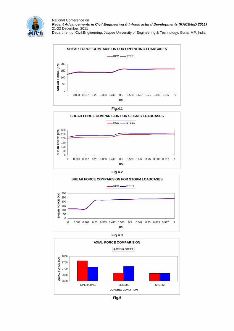
National Conference on Recent Advancements in Civil Engineering & Infrastructural Developments (RACE-InD 2011) 21-22 December, 2011 Department of Civil Engineering, Jaypee University of Engineering & Technology, Guna, MP, India
SHEAR FORCE COMPARISION FOR OPERATING LOADCASES
0
50
100
150
200
0 0.083 0.167 0.25 0.333 0.417 0.5 0.583 0.667 0.75 0.833 0.917 1
H/L
SHEA
R FO
RCE
(KN)
RCC STEEL
Fig.4.1
SHEAR FORCE COMPARISION FOR SEISMIC LOADCASES
050
100150200250300
0 0.083 0.167 0.25 0.333 0.417 0.5 0.583 0.667 0.75 0.833 0.917 1
H/L
SHEA
R FO
RCE
(KN)
RCC STEEL
Fig.4.2
SHEAR FORCE COMPARISION FOR STORM LOADCASES
050
100150200250300
0 0.083 0.167 0.25 0.333 0.417 0.583 0.5 0.667 0.75 0.833 0.917 1
H/L
SH
EA
R F
OR
CE
(KN
)
RCC STEEL
Fig.4.3
AXIAL FORCE COMPARISION
2600
2650
2700
2750
2800
OPERATING SEISMIC STORM
LOADING CONDITION
AXIA
L FO
RCE
(KN)
RCC STEEL
Fig.5

National Conference on Recent Advancements in Civil Engineering & Infrastructural Developments (RACE-InD 2011) 21-22 December, 2011 Department of Civil Engineering, Jaypee University of Engineering & Technology, Guna, MP, India
DEFLECTION COMPARISION
0
20
40
60
80
100
OPERATING SEISMIC STORM
LOADING CONDITION
DEFL
ECTI
ON
(MM
)RCC STEEL
Fig.6
COMPARISION OF FORCES FOR PILE-CAP BEAM
01000200030004000
Hogging atsupport (KN.m)
Sagging atsupport (KN.m)
Sagging at mid-span (KN.m)
Shear atsupport (KN)
FORCES
VALU
E
RCC Steel
Fig.7
COMPARISION OF FORCES FOR LONGITUDINAL BEAMS
0
500
1000
1500
Hogging at support(KN.m)
Sagging at mid-span(KN.m)
Shear at support(KN.m)
FORCES
VAL
UE
RCC STEEL
Fig.8

National Conference on Recent Advancements in Civil Engineering & Infrastructural Developments (RACE-InD 2011) 21-22 December, 2011 Department of Civil Engineering, Jaypee University of Engineering & Technology, Guna, MP, India
Fig.9 General Arrangement Drawing

National Conference on Recent Advancements in Civil Engineering & Infrastructural Developments (RACE-InD 2011) 21-22 December, 2011 Department of Civil Engineering, Jaypee University of Engineering & Technology, Guna, MP, India
6 References Aswani M.G. and Vazirani V.N. and Ratwani M.M., Design Of Concrete Bridges, Khanna Publishers
Babu P.V.Mayur and Bhandari N.M. A Comparative Study Of Integral Bridges Versus Simply Supported Bridge.
Bowles Joseph E., Foundation Analysis And Design, The McGraw-Hill Companies, Inc., Fifth Edition.
Broms Bengt B., Design Of Laterally Loaded Piles
Byrne Byron, Driven Pipe Piles In Dense Sand
Chen Wai Fah and Duan Lian, Bridge Engineering Handbook, CRC Press.
Connal John, Integral Abutment Bridges – Australian And US Practice
Dawson Thomas H., Offshore Structural Engineering, United Status Naval Academy
Elson W.K., Design Of Laterally Loaded Piles
Evans Keith Martin, A model Study Of The End Bearing Capacity Of Piles In Layered Calcareous Soils
Flener Esra Bayoglu, Soil Structure Interaction in Integral Bridges
Mistry Vasant C., Integral Abutment And Jointless Bridges
O’brien Eugene J. and Keogh Damien L., Design Details Of Integral Bridges.
Park R.and Paulay T., Reinforced Concrete Structure, John Willey And Sons Publications.
Poulos H.G. and Davis E.H., Pile Foundation Analysis And Design, John Willey And Sons Publications.
Prakash Shamsher and Sharma Hari D., Pile Foundations In Engineering Practice, John Willey And Sons Publications.
Raina V.K., Concrete Bridge Practice, The McGraw-Hill Publishing Company Liminted, Second Edition.
Reynolds Charles E. and Steedman James C., Reinforced Concrete Designer’s Handbook, E & F N Spon Publications,Tenth Edition.
API Recommended Practice 2A-WSD Recommended Practice For Planning, Designing And Constructing Fixed Offshore Platforms – Working Stress Design
BS:6349(Part1)-2000 Maritime Structures- Code Of Practice For General Criteria.
Coastal Engineering Manual(Part VI)- 2006 Chapter5 – Fundamentals Of Design.
IS:1893(Part 1)-2002 Code Of Practice For Earthquake Resistant Design Of Structures- General Provisions And Buildings.
IS:1893-1984 Criteria For Earthquake Resistant Design Of Structures.
IS:2911 (Part 1/Sec 2) – 1979 Code Of Practice For Design And Construction Of Piles, Bored Cast In Situ Piles
IS:456-2000 Plain And Reinforced Concrete – Code Of Practice
IS:4651 (Part 4) -1989 Code Of Practice For Planning And Design Of Ports And Harbours, General Design Considerations.
IS:800-1984 Code Of Practice For General Construction In Steel
IS:816-1969 Code Of Practice For Use Of Metal Arc Welding For General Construction In Mild Steel
The paper may be considered for
1. Oral Presentation √ 2. Poster Session

Dear Sir/Madam, Thanks for acceptance of abstract. I am attaching full length paper for your pursual. Please feel free to communicate me if any modification is required or if any further information is required. My contact details are as follows: Name: Viral Panchal email id: [email protected] Contact No:+919099055654
From: RACE-InD2011 <[email protected]> To: viral panchal <[email protected]> Sent: Fri, 29 July, 2011 12:50:36 PM Subject: ABSTRACT ACCEPTANCE NOTIFICATION_RACE-InD2011 Dear Sir/Madam, We are pleased to inform that the Abstract of your paper has been accepted after review. We request you to submit your full length paper not exceeding 6 pages in length and strictly conforming to the formatting guidelines. A template file is attached herewith to help you in preparing full length manuscript. The completed paper must be emailed to [email protected] at the earliest but in no case later than August 15, 2011 so that the paper can be sent for review well in time. Acceptance of the papers after review will be notified to the authors via e‐mail by 20 September, 2011. Please note that the paper will be finally accepted for presentation and publication in the Conference Proceedings only if at least one of its authors is exclusively registered for this paper so that other delegates may benefit from the presentation and a more interactive and fruitful discussion. While sending the full length paper, please mention the e‐mail ID, contact number and address of the author who will present the paper. With warm regards, Dr. Amit Srivastava Organizing Secretary RACE‐InD 2011 Department of Civil Engineering Jaypee University of Engineering & Technology Raghogarh, Guna, MP – 473226 INDIA
Print - Close Window
Subject: Re: ABSTRACT ACCEPTANCE NOTIFICATION_RACE-InD2011 From: viral panchal ([email protected]) To: [email protected]; Cc: [email protected]; Date: Fri, 29 Jul 2011 17:40:04
Page 1 of 2Print
8/9/2011http://in.mg4.mail.yahoo.com/neo/launch?.rand=etree9k31lrpa

On Fri, Jul 8, 2011 at 11:33 PM, viral panchal <[email protected]> wrote:
Dear Sir/Madam, I wish to participate in the event "National Conference On Recent Advancements In Civil Engineering & Infrastructural Development" being organized in your esteemed institute under "Structural Engineering Theme". For that, I have attached the abstract of the paper "A Comparative Study Of RCC & Steel Pile Foundation For An Integral Bridge" along with this mail for your kind consideration. Please acknowledge receipt of this mail by a return mail. Also, please let me know the date for notification of accepted abstract. Best Regards, Viral Panchal. Mobile No-9099055654
Page 2 of 2Print
8/9/2011http://in.mg4.mail.yahoo.com/neo/launch?.rand=etree9k31lrpa

1
INTEGRAL BRIDGES Viral Panchal1 and Chaitanya S. Sanghvi2
1M.E. (CASAD) Student, Applied Mechanics Department, L.D.College Of Engineering, India.
E-mail: [email protected] 2 Associate Professor, Applied Mechanics Department, L.D.College Of Engineering, India.
E-mail: [email protected]
ABSTRACT The increase in demand for complex roadway alignments, advances in construction technology and availability
of computing power for bridges design, are some of the factors for developments in bridge engineering. Concept
of “Integral Bridges” is one of these developments. Due to ease & economy in construction and maintenance, it
is also getting popular in India. Integral bridge concept is also widely adopted in marine structures where many
times foundations are flexible like pile foundation. Main reasons for increasing popularity of integral concept in
marine structures are efforts of minimizing use of bearings and to resist large lateral forces. Integral bridge
requires flexible foundation to accommodate thermal stresses and stresses produced from lateral forces like
waves, current, wind, seismic etc. There are many advantages to jointless bridges as many are performing well
in service. There are long term benefits to adopting integral bridges concept and therefore there should be
greater use of integral bridge construction. Integral abutment and jointless bridges cost less to construct and
require less maintenance then equivalent bridges with expansion joints. This paper explains why we should use
integral bridges and discusses some of the recommended practices for integral abutment and jointless bridges.
Keywords Integral bridge, bearing, seismic, expansion joint, abutment, soil structure interaction.
Why Integral Bridges? One of the most important aspects of design which can affect structure life and maintenance costs is the
reduction or elimination of roadway expansion joints and associated expansion bearings. Unfortunately, this is
too often overlooked or avoided. Joints and bearings are expensive to buy, install, maintain and repair and more
costly to replace. The most frequently encountered corrosion problem involves leaking expansion joints and
seals that permit salt-laden run-off water from the roadway surface to attack the girder ends, bearings and
supporting reinforced concrete substructures. Elastomeric glands get filled with dirt, rocks and trash, and
ultimately fail to function. Many of our most costly maintenance problems originated with leaky joints. Bridge
deck joints are subjected to continual wear and heavy impact from repeated live loads as well as continual stages
of movement from expansion and contraction caused by temperature changes, and or creep and shrinkage or
long term movement effects such as settlement and soil pressure. Joints are sometimes subjected to impact
loadings which can exceed their design capacity.
Deck joints are routinely one of the last items installed on a bridge and are sometimes not given the
necessary attention it deserves to ensure the desired performance. While usually not a significant item based on
cost, bridge deck joints can have a significant impact on a bridge performance. A wide variety of joints have
been developed over the years to accommodate a wide range of movements, and promises of long lasting,
durable, effective joints have led States to try many of them. Some joint types perform better than others, but all

2
joints can cause maintenance problems. The problems arising from provision of bearings and expansion joints
can be summarized as:
• Increased incidence of inspection and maintenance required, bridge durability is often impaired.
• Necessity of replacement during the service life of the bridge since their design life is lesser than that
of the rest of the bridge elements.
• Decrease in redundancy and difficulties in providing adequate ductility for resisting earthquake
effects, leading to larger earthquake design forces.
Surajbari new bridge superstructure shifted in the transverse direction.
Bridge between Surajbari & Bhachau – Violent shaking has resulted in pier head being damaged due to
pounding of deck

3
Possibilities of dislodgement of superstructure during accidental loads, especially those due to
earthquakes, is a clear danger requiring expensive and clumsy attachments. The latest amendments to the Indian
Road Congress codes require the positive measures such as restrainers be provided so that girders do not get
dislodged during earthquake.
• Bridges presents soft target for terrorists who could put them out of service with little difficulty.
What is An Integral Bridge? Because of above mentioned problems, use of integral or integral abutment bridge is being increased
all over the world. Integral bridges are bridges where the superstructure is continuous and connected
monolithically with the substructure with a moment-resisting connection. As an effect we obtain a structure
acting as one unit. However, simply supported bridges are still popular in India. The main reason for their
popularity is that these structures are simple to design and execute. The sub-structural design is also greatly
simplified because of the determinate nature of the structure. Sometimes there are situations where
bearings/simply supported spans/expansion joints can not be altogether avoided because of the length of the
bridge. In such cases intermediate joints will be provided with bearings to allow horizontal movements. But
these joints will be lesser in numbers as compared to simply supported bridges. On the other hand, monolithic
joints and redundancy of the structural system do result in savings in the cost of the construction and
maintenance. Elimination of bearings improves the structural performance during earthquakes. Finally, integral
form of construction will require lesser inspection and maintenance efforts. Several urban structures in India
have been built with this concept. However no national standards or uniform policy regarding the permissible
bridge length, skews and design procedures have been clearly established, although certain general concepts
become common in practice.
The advisory note BA 42/96 recommends that all bridges need to be integral if overall length exceeds
60 m and skews less than 30 deg. The longitudinal movement in the bridge abutment is limited to 20mm from
the position at time of restraint during construction. Integral bridges are designed for same range of temperatures
as other bridges. According to IAJB 2005, the range of design criteria for selection of integral bridge is
summarized below.
Steel girders Concrete
Maximum span (ft) 65-300 60-200
Total length (ft) 150-650 150-1175
Maximum skew (degree) 15-70 15-70
Maximum curvature 0-10 0-10
Some of the common features of monolithic bridge construction include:
i) Elimination of the pier cap which improves bridge aesthetics.
ii) Heavily reinforced slender piers
iii) Change in the structural system.
Integral bridges accommodate superstructure movements without conventional expansion joints. With
the superstructure rigidly connected to the substructure and with flexible substructure piling, the superstructure
is permitted to expand and contract. Such bridges are the answer for small and medium length bridges where
bearings and expansion joints can be either eliminated altogether or reduced to a minimum. By incorporation of

4
intermediate expansion joints, the integral bridge concept can be extended to long bridges and viaducts too.
Integral bridges are designed to provide resistance to thermal movements, breaking forces, seismic forces and
winds by the stiffness of the soil abutting the end supports and the intermediate supports. A typical three span
integral abutment bridge is shown in Fig.1.
Fig.2 shows three principle methods by which an integral bridge can accommodate movements of the
super structure. Fig.3 shows different types of end supports used for integral bridges. The main types of the end
supports can be categorized and described as:
a). Frame abutment:- Full height frame abutments are suitable for short single-span bridges. The
horizontal movements will only be small, so the earth pressures should not be very high.
b). Embedded wall abutment:- Embedded wall abutments are also suitable for short single-span
integral bridges.
c). Piled abutment with reinforced soil wall :- A piled abutment with reinforced soil abutment wall
and wing walls is a form of construction that should have a wide application.
d). End screen (semi integral) :- Semi-integral construction with bearings on top of a rigid retaining
wall is a design method that can be used for full-height abutments for bridges of any length. Jacking of the deck
can result in soil movement under the abutment soffit. This can obstruct the deck from returning to its original
level.
e). Piled bank seat :- Piled bank seats are recommended for widespread use. The piles prevent
settlement while allowing horizontal movement and rotation.
f). Piled bank seat with end screen (semi integral):- Bank seats can be designed as semi-integral
abutments. The footing is not required to move horizontally and piled or spread footings can be used.
g). Bank pad abutment :- Shallow abutments on spread footings are only considered to be suitable
for situations where the foundation is very stiff and there can be no settlement problems. A granular fill layer
should be placed below the footing to allow sliding.
Benefits of Integral Bridges Some of the advantages of adopting Integral bridges over that of the conventional bridges are summarized
below:
i. Simplified Construction- The simple characteristics of integral bridges make for rapid and
economical construction. For example, there is no need to construct cofferdams, make footing
excavations, place backfill, remove cofferdams, and prepare bridge seats, place bearings, back
walls, and deck joints. Instead, integral construction generally results in just four concrete
placement days. After the embankments, piles and pile caps have been placed and deck stringers
erected, deck slabs, continuity connections, and approach slabs can follow in rapid succession.
ii. No bearings and Joints- Integral bridges can be built without bearings and deck joints. Not only
will this result in savings in initial costs, the absence of joints and bearings will reduce
maintenance efforts. This is an important benefit because presently available deck joint sealing
devices have such short effective service lives. Smooth jointless construction improves vehicular
riding quality and diminishes vehicular impact stress levels.

5
iii. Improved Design efficiency- Tangible efficiencies are achieved in substructure design due to an
increase in the number of supports over which longitudinal and transverse superstructure loads
may be distributed. Built-in abutments can be designed to accommodate some bending moment
capacity, reducing end span bending moments with possible savings in end span girders. Due to
rigid connection between superstructure and substructure, bending moments are considerably less
thus resulting in smaller sections and economy in reinforcement and concrete.
iv. Enhanced load distribution- One of the most important attributes of integral bridges is their
substantial reserve strength capacity. The integrity of their unified structural system makes them
extremely resistant to the potentially damaging effects of illegal super imposed loads, pressures
generated by the restrained growth of jointed rigid pavements, earthquakes, and debris laden flood
flows. A joint less bridge with integral abutments will have a higher degree or redundancy that
may be beneficial in earthquake zones. The problem of retaining the superstructure on its bearing
during seismic events is eliminated and the inherent damping of the integral bridge structural
system allows it to better absorb energy and limit damage.
v. Added redundancy and capacity for catastrophic events - Integral abutments provide added
redundancy and capacity for catastrophic events. Joints introduce a potential collapse mechanism
into the overall bridge structure. Integral abutments eliminate the most common cause of damage
to bridges in seismic events, loss of girder support. Integral abutments have consistently performed
well in actual seismic events and significantly reduced or avoided problems such as back wall and
bearing damage, associated with seat type jointed abutments. Jointless design is preferable for
highly seismic regions.
The reasons for adopting integral bridges in India and elsewhere could be quite different. When
earthquake forces like predominant or when considerations like increased resistance to blast are to be reckoned
with or there is a strong need of incorporating reduced cost of inspection & maintenance integral bridge concept
is an excellent option.
Problems and Uncertainties Despite the significant advantages of integral abutment bridges, there are some problems and
uncertainties associated with them. Many articles, mentioned that the main problem connected with integral
bridges are consequences of temperature variations and traffic loads, which cause horizontal bridge movements.
Horizontal movements and rotations of the abutment cause settlement of the approach fill, resulting in a void
near abutment if the bridge has approach slabs. Effects of lateral movements of integral abutments under cyclic
loadings are obvious problem which demands solving, but positive aspect in this case is that temperature
induced displacements in the traditional bridge is over twice bigger than displacement at the end of (considering
objects with the same span length) integrated structure because of symmetrical nature of the thermal effects as
illustrated below..

6
The other uncertainties connected with designing and performance of integral abutment bridges are:
The elimination of intermediate joints in multiple spans results in a structural continuity that may
induce secondary stresses in the superstructure. These forces due to shrinkage, creep, thermal gradients,
differential settlement, differential deflections, and earth pressure can cause cracks in concrete bridge
abutments. Wingwalls can crack due to rotation and contraction of the superstructure. Also, differential
settlement of the substructure can cause more damage in case of integral bridges as compared to traditional
briges.
Integral bridges should be provided with approach slabs to prevent vehicular traffic from consolidating
backfill adjacent to abutments, to eliminate live load surcharging of backfill, and to minimize the adverse effect
of consolidating backfill and approach embankments on movement of vehicular traffic. For bridges with closed
decks (curbs, barriers, etc.), approach slabs should be provided with curbs to confine and carry deck drainage
across backfill to the approaches and prevent erosion, or saturation and freezing of the backfill.
The piles that support the abutments may be subjected to high stresses as a result of cyclic elongation
and contraction of the bridge structure. These stresses can cause formation of plastic hinges in the piles and may
reduce their axial load capacities.
The application of integral bridge concept has few other limitations. Integral bridges can not be used
with weak embankments or subsoil, and they can only be used for limited lengths, although the maximum length
is still somewhat unclear. Integral bridges are suitable if the expected temperature induced moment at each
abutment is certain value specified by suitable authorities in every country, and somewhat larger moments can
be tolerable.
Recommended Design Details for Integral Abutments • Use embankment and stub-type abutments.
• Use single row of flexible piles and orient piles for weak axis bending.
• Use steel piles for maximum ductility and durability.
• Embed piles at least two pile sizes into the pile cap to achieve pile fixedly to abutment.
• Provide abutment stem wide enough to allow for some misalignment of piles.
• Provide an earth bench near superstructure to minimize abutment depth and wingwall lengths.
• Provide minimum penetration of abutment into embankment.
• Make wingwalls as small as practicable to minimize the amount of structure and earth that have to
move with the abutment during thermal expansion of the deck.
• For shallow superstructures, use cantilevered turn-back wingwalls (parallel to center line of
roadway) instead of transverse wingwalls.
• Provide loose backfill beneath cantilevered wingwalls.
• Provide well-drained granular backfill to accommodate the imposed expansion and contraction.

7
• Provide under-drains under and around abutment and around wingwalls.
• Encase stringers completely by end-diaphragm concrete.
• Paint ends of girders.
• Caulk interface between beam and backwall.
• Provide holes in steel beam ends to thread through longitudinal abutment reinforcement.
• Provide temporary support bolts anchored into the pile cap to support beams in lieu of cast bridge
seats.
• Tie approach slabs to abutments with hinge type reinforcing.
• Use generous shrinkage reinforcement in the deck slab above the abutment.
• Pile length should not be less than 10 ft. to provide sufficient flexibility.
• Provide pre bored holes to a depth of 10 feet for piles if necessary for dense and/or cohesive soils
to allow for flexing as the superstructure translates.
• Provide pavement joints to allow bridge cyclic movements and pavement growth.
• Focus on entire bridge and not just its abutments.
• Provide symmetry on integral bridges to minimize potential longitudinal forces on piers and to
equalize longitudinal pressure on abutments.
• Provide two layers of polyethylene sheets or a fabric under the approach slab to minimize friction
against horizontal movement.
• Limit use of integral abutment to bridges with skew less than 30 degree to minimize the magnitude
and lateral eccentricity of potential longitudinal forces.
Summary
There are many advantages to jointless bridges as many are performing well in service. There are long-
term benefits to adopting integral bridge design concepts and therefore there should be greater use of integral
bridge construction. Due to limited funding sources for bridge maintenance, it is desirable to establish strategies
for eliminating joints as much as possible and converting/retrofitting bridges with troublesome joints to jointless
design.
Now various organizations and authorities have adopted integral abutment bridges as structures of
choice when conditions allow. Many of them are now building integral and/or semi-integral abutment type of
bridges. Recently in India, this concept is widely used in Delhi Metro Rail bridges.
While superstructures with deck-end joints still predominate, the trend appears to be moving toward
integral. Although no general agreement, regarding a maximum safe-length for integral abutment and jointless
bridges, exists among standards or organisations, the study has shown that design practices followed by the most
organizations are conservative and longer jointless bridges could be constructed.
Continuity and elimination of joints, besides providing a more maintenance free durable structure, can
lead the way to more innovative and aesthetically pleasing solutions to bridge design. As bridge designers we
should never take the easy way out, but consider the needs of our customer, the motoring public first. Providing
a joint free and maintenance free bridge should be our ultimate goal. The best joint is no joint.

8
References 1) Babu P.V.Mayur and Bhandari N.M. A Comparative Study Of Integral Bridges Versus Simply
Supported Bridge.
2) Chen Wai Fah and Duan Lian, Bridge Engineering Handbook, CRC Press.
3) Connal John, Integral Abutment Bridges – Australian And US Practice
4) Flener Esra Bayoglu, Soil Structure Interaction in Integral Bridges
5) O’brien Eugene J. and Keogh Damien L., Design Details Of Integral Bridges.
6) Raina V.K., Concrete Bridge Practice, The McGraw-Hill Publishing Company Liminted, Second
Edition.

9
Fig.1 Sketch Of A Typical 3 Span Integral Bridge
Fig.2

10
(a) (b)
(c) (d) (e) (f) (g) (g)
Fig.3

Reply to SED Info
Dear Sir, please find attached letter of acceptance of your article for publication in SED. regards,Editorial Team,SED
1 Attached files | 126KB
Acceptance of paper for submission
FROM:
TO:
Friday, 5 August 2011 4:36 PM
letter of ac…
Page 1 of 1
8/9/2011http://36ohk6dgmcd1n.yom.mail.yahoo.net/om/api/1.0/openmail.app.invoke/36ohk6dgm...

Dear Mr. Viral Panchal, Date: 05-08-2011
We are thankful to you for sending the article on “Integral bridges” for publishing in Structural
Engineering Digest. We are glad to inform you that the article will be published in the next issue of SED.
We will be looking forward to some more of such interesting contributions from you.
Thank you once again.
Regards,
Editorial Team
Structural Engineering Digest
(www.sedigest.in)
For Communication: SED, Chitrakoot flats, B/H Times of India, Ashram Road, Ahmedabad – 380009
Phone: +91 (79) 2658 8829/2480/4488. Fax: +91 (79) 2658 3596
Email: [email protected]
Website: www.sedigest.in
![THESIS TITLE A THESIS SUBMITTED TO THE MIDDLE EAST ...ii.metu.edu.tr/system/files/documents/thesis... · [SAMPLE 1] Approval of the thesis: THESIS TITLE Submitted by STUDENT NAME](https://img.pdfslide.net/doc/110x75/6019035f39977162fc4f0b03/thesis-title-a-thesis-submitted-to-the-middle-east-iimetuedutrsystemfilesdocumentsthesis.jpg)