Embed Size (px)
Citation preview

NAVAL POSTGRADUATE SCHOOLMonterey, California
THESIS
Approved for public release; distribution is unlimited
TACTICAL VOICE COMMUNICATIONS OVERSHIPBOARD LOCAL AREA NETWORKS
by
Glenn R. Urie
December 2001
Thesis-Co Advisors: Luqi John Osmundson

Report Documentation Page
Report Date 19 Dec 2001
Report Type N/A
Dates Covered (from... to) -
Title and Subtitle Tactical Voice Communications Over Shipboard LocalArea Networks
Contract Number
Grant Number
Program Element Number
Author(s) Urie, Glenn
Project Number
Task Number
Work Unit Number
Performing Organization Name(s) and Address(es) Naval Postgraduate School Monterey, California
Performing Organization Report Number
Sponsoring/Monitoring Agency Name(s) and Address(es)
Sponsor/Monitor’s Acronym(s)
Sponsor/Monitor’s Report Number(s)
Distribution/Availability Statement Approved for public release, distribution unlimited
Supplementary Notes The original document contains color images.
Abstract
Subject Terms
Report Classification unclassified
Classification of this page unclassified
Classification of Abstract unclassified
Limitation of Abstract UU
Number of Pages 118


i
REPORT DOCUMENTATION PAGE Form Approved OMB No. 0704-0188
Public reporting burden for this collection of information is estimated to average 1 hour per response, including the time for reviewing instruction,searching existing data sources, gathering and maintaining the data needed, and completing and reviewing the collection of information. Sendcomments regarding this burden estimate or any other aspect of this collection of information, including suggestions for reducing this burden, toWashington headquarters Services, Directorate for Information Operations and Reports, 1215 Jefferson Davis Highway, Suite 1204, Arlington, VA22202-4302, and to the Office of Management and Budget, Paperwork Reduction Project (0704-0188) Washington DC 20503.
1. AGENCY USE ONLY (Leave blank) 2. REPORT DATEDecember 2001
3. REPORT TYPE AND DATES COVEREDMaster’s Thesis
TITLE AND SUBTITLE : SOFTWARE SPECIFICATIONS AND REQUIREMENTS FORINTEGRATION OF THE SHIPBOARD TACTICAL VOICE COMMUNICATIONSSYSTEMS INTO THE DATA DISTRIBUTION INFRASTRUCTURE.
5. FUNDING NUMBERS
6. AUTHOR(S)Urie, Glenn R.
7. PERFORMING ORGANIZATION NAME(S) AND ADDRESS(ES)Naval Postgraduate SchoolMonterey, CA 93943-5000
8. PERFORMINGORGANIZATION REPORTNUMBER
9. SPONSORING / MONITORING AGENCY NAME(S) AND ADDRESS(ES) 10. SPONSORING /MONITORINGAGENCY REPORT NUMBER
11. SUPPLEMENTARY NOTES The views expressed in this thesis are those of the author and do not reflect the officialpolicy or position of the Department of Defense or the U.S. Government.12a. DISTRIBUTION / AVAILABILITY STATEMENT
Approved for public release; distribution is unlimited.12b. DISTRIBUTION CODE
13. ABSTRACT (maximum 200 words)The United States Navy’s next generation ship(s) scheduled for commissioning in the year 2004 and beyond will
integrate tactical shipboard voice communications systems into the local area network (LAN). A single network eliminates separatevoice and data infrastructures, consolidates services, and reduces the cost of communications. The existing installation of high-speed shipboard data networks has laid the foundation for the convergence of these two technologies.
Currently, there is no high level definition of how multiple system types will share a common infrastructure. Neither isthere a baseline defining acceptable end-to-end standards for the merger of these two systems. Common practice for demonstratingfeasibility is confined to using commercial-off-the-shelf (COTS) equipment in a show-and-tell environment. Although thisindicates certain operational features it does not demonstrate if telephony system’s performance are within specified limits. Neitherdoes this type of demonstration simulate realistic shipboard tactical load performance requirements or what effect this integrationwill have on data systems that co-habitat the LAN.
The purpose of this thesis is to define the convergence of the centralized shipboard tactical voice communicationcommunications system into a distributed software-based system and the minimum set of acceptable software requirements for fullintegration of this system into the existing shipboard local area network infrastructure. In addition, this thesis will address thequality of service, tactical requirements risk assessment, interoperability, training, integration with legacy systems and other factorsinvolved in the total cost of ownership.14. SUBJECT TERMSTelephony Server, PBX, Tactical, Net Calling, Quality of Service, COTS
15. NUMBER OF PAGES110
16. PRICE CODE
17. SECURITY CLASSIFI-CATION OF REPORTUnclassified
18. SECURITY CLASSIFI-CATION OF THIS PAGEUnclassified
19. SECURITY CLASSI-FICATION OF ABSTRACTUnclassified
20. LIMITATION OFABSTRACTUL
NSN 7540-01-280-5500 Standard Form 298 (Rev. 2-89) Prescribed by ANSI Std. 239-18

ii


iv
THIS PAGE INTENTIONALLY LEFT BLANK

v
ABSTRACT
The United States Navy’s next generation ship(s) scheduled for commissioning inthe year 2004 and beyond will integrate tactical shipboard voice communications systeminto the local area network (LAN). A single network eliminates separate voice and datainfrastructures, consolidates services, and reduces the cost of communications. Theexisting installation of high-speed shipboard data networks has laid the foundation for theconvergence of these two technologies.
Currently, there is no high level definition of how multiple system types will sharea common infrastructure. Neither is there a baseline defining acceptable end-to-endstandards for the merger of these two systems. Common practice for demonstratingfeasibility is confined to using commercial-off-the-shelf (COTS) equipment in a show-and-tell environment. Although this indicates certain operational features it does notdemonstrate if telephony system’s performance are within specified limits. Neither doesthis type of demonstration simulate realistic shipboard tactical load performancerequirements or what effect this integration will have on data systems that co-habitat theLAN.
The purpose of this thesis is to define the convergence of the centralizedshipboard tactical voice communication communications system into a distributedsoftware-based system and the minimum set of acceptable software requirements for fullintegration of this system into the existing shipboard local area network infrastructure. Inaddition, this thesis will address the quality of service, tactical requirements riskassessment, interoperability, training, integration with legacy systems and other factorsinvolved in the total cost of ownership.

vi
THIS PAGE INTENTIONALLY LEFT BLANK

vii
TABLE OF CONTENTS
I. INTRODUCTION................................................................................................................................. 1
II. SHIPBOARD TELEPHONY REQUIREMENTS ............................................................................... 3
A. INTRODUCTION .................................................................................................................. 3
B. EXISTING SHIPBOARD TELEPHONE SYSTEM.............................................................. 4
C. VOICE OVER THE SHIPBOARD NETWORK ................................................................... 101. Elements Affecting Quality Of Service (QoS)......................................................... 10
a. Latency ....................................................................................................... 11b. Jitter............................................................................................................ 12c. Clock Synchronization................................................................................ 14d. Talker Overlap............................................................................................ 15e. Voice Compression .................................................................................... 16f. Silence Suppression.................................................................................... 17g. Echo Suppression ....................................................................................... 17
2. Mean Opinion Score (MOS).................................................................................... 18
III. TELEPHONY BASED TACTICAL SHIPBOARD COMMUNICATION SYSTEMS..................... 21
A. TACTICAL TELEPHONY .................................................................................................... 211. Threat Description ................................................................................................... 222. Interoperability ........................................................................................................ 243. Scalability ................................................................................................................ 254. Granularity............................................................................................................... 265. Redundancy ............................................................................................................. 266. Standards-Based Telephony .................................................................................... 27
B. SYSTEM PERFORMANCE CAPABILITIES....................................................................... 271. Traffic ...................................................................................................................... 282. Blocking Criterion ................................................................................................... 293. Call Setup Time / Setting Up a Connection............................................................. 304. Automatic Route Selection ...................................................................................... 305. Warm Reset Time.................................................................................................... 31
IV. INTEGRATING TACTICAL VOICE OVER THE SHIPBOARD NETWORK................................ 33
A. OVERVIEW ........................................................................................................................... 33
B. BROKERING ......................................................................................................................... 33
C. RESOURCE CONTROL AND ALLOCATION .................................................................... 35
D. COMPUTER TELEPHONY .................................................................................................. 381. Telephony Server..................................................................................................... 402. Trinary Interface ...................................................................................................... 413. System Administration Interface.............................................................................. 444. Internal Diagnostics Testing .................................................................................... 44
viii
5. Hot Switchover ........................................................................................................ 45
E. STANDARD NETWORK TERMINAL INTERFACE.......................................................... 46
F. NETWORK TERMINALS..................................................................................................... 471. Plain Old Telephone (POTS) Network Terminal .................................................... 482. Sound Power Phone Network Terminal................................................................... 483. Primary Tactical Terminal Equipment..................................................................... 494. Secure Terminal Equipment (STE) Network Terminal ........................................... 51
G. TRUNK LINE INTERFACES................................................................................................ 521. Integrated Services Digital Network (ISDN)........................................................... 532. Basic Rate Interface (BRI) UP0 .............................................................................. 553. E1 / T1 Public Automated Branch Exchange (PBAX) ............................................ 55
H. BASIC PBX SOFTWARE SERVICES.................................................................................. 561. Introduction ............................................................................................................. 562. Call Progression Tones............................................................................................ 57
a. Dial Tone.................................................................................................... 59b. Ring Tones ................................................................................................. 59c. Busy Tones ................................................................................................. 61d. Unavailable Tone ....................................................................................... 62e. Alerting Tone ............................................................................................. 62f. Recall Dial Tone......................................................................................... 63g. Confirmation Tone ..................................................................................... 63h. Howler Tone............................................................................................... 63i. Calibration Tones ....................................................................................... 64j. Call Progression Tone Summary ................................................................ 64
3. Direct Inward Dialing .............................................................................................. 664. Direct Outward Dialing ........................................................................................... 675. Automatic Route Selection ...................................................................................... 686. Net (Conference) Calling......................................................................................... 687. Sound Powered Nets................................................................................................ 69
a. Abbreviated And Speed Calling ................................................................. 708. 18-Digit International Number Routing................................................................... 719. Caller Identification................................................................................................. 7110. Call Waiting............................................................................................................. 7211. Call Forwarding....................................................................................................... 7212. Call Hold ................................................................................................................. 7313. Call Park .................................................................................................................. 7314. Call Transfer ............................................................................................................ 7415. Call Groups.............................................................................................................. 7416. Camp-On ................................................................................................................. 7417. Messaging................................................................................................................ 7518. Voice Mail ............................................................................................................... 7519. Push To Talk (PPT)................................................................................................. 7620. Special Connection Terminals ................................................................................. 7621. Shipboard Alarms .................................................................................................... 7722. Class Of Service ...................................................................................................... 7723. Classmarks............................................................................................................... 7824. Classified Communications ..................................................................................... 7825. Sensitive Communications....................................................................................... 78
ix
I. SHIPBOARD DATA NETWORKS....................................................................................... 791. Introduction ............................................................................................................. 792. Elements Affecting Shipboard Networks................................................................. 793. Shipboard Local Area Networks.............................................................................. 81
a. Carrier Sense Multiple Access / Collision Detection (CSMA/CD) ............ 81b. Token Ring ................................................................................................. 83
J. SHIPBOARD DATA BACKBONES..................................................................................... 841. Asynchronous Transfer Mode (ATM) ..................................................................... 842. Fiber Distribution Data Interface (FDDI) ................................................................ 86
V. COST OF OWNERSHIP ..................................................................................................................... 89
A. INTRODUCTION .................................................................................................................. 89
B. SYSTEM RELIABILITY ....................................................................................................... 89
C. SOFTWARE SYSTEM MANAGEMENT............................................................................. 90
D. SYSTEM MAINTANCE........................................................................................................ 91
E. COST ...................................................................................................................................... 91
F. MODULAR DESIGN AND OPEN STANDARDS FOR INTEROPABILITY..................... 93
VI. CONCLUSIONS ................................................................................................................................. 95
A. CONCLUSIONS..................................................................................................................... 95
LIST OF REFERENCES........................................................................................................................... 99
INITIAL DISTRIBUTION LIST .............................................................................................................. 101

x
THIS PAGE INTENTIONALLY LEFT BLANK

xi
LIST OF FIGURES
FIGURE 1. TIME SLICE PROCESSING................................................................................................................. 5FIGURE 2. TACTICAL SWITCH BLOCK DIAGRAM ............................................................................................. 9FIGURE 3. SIGNAL QUALITY........................................................................................................................... 19FIGURE 4. STATE DIAGRAM FOR PHONE LINE ............................................................................................... 22FIGURE 5. BROKERING MANAGEMENT .......................................................................................................... 34FIGURE 6. EVENT TRACE FOR PHONE CALL .................................................................................................. 36FIGURE 7. CALL SETUP INTERACTION DIAGRAM............................................................................................ 37FIGURE 8. BASIC TACTICAL TELEPHONY SYSTEM ......................................................................................... 38FIGURE 9. TACTICAL TELEPHONY BLOCK DIAGRAM ..................................................................................... 39FIGURE 10. VOICE AND DATA CONVERGENCE OVER BROADBAND BLOCK DIAGRAM .................................. 41FIGURE 11. POTS TRINARY NETWORK INTERFACE....................................................................................... 42FIGURE 12. NETWORK CENTRIC TACTICAL TELEPHONY SYSTEM .................................................................. 43FIGURE 13. SOUND POWERED CONNECTION DIAGRAM.................................................................................. 49FIGURE 14. BUS INTERFACE DIAGRAM .......................................................................................................... 54FIGURE 15. CALL PROGRESSION DIAL TONE EVENT TRACE .......................................................................... 59FIGURE 16. RING TONE EVENT TRACE .......................................................................................................... 61FIGURE 17. INTEGRATED TERMINAL EQUIPMENT BLOCK DIAGRAM .............................................................. 70

xii
THIS PAGE INTENTIONALLY LEFT BLANK

xiii
LIST OF TABLES
TABLE 1. TERMINAL INTERFACE REQUIREMENTS............................................................................................ 7TABLE 2. TRUNKLINE INTERFACE REQUIREMENTS .......................................................................................... 7TABLE 3. DATA VERSIS VOICE TRANSMISSION CRITERIA .............................................................................. 11TABLE 4. AVERAGE LATENCY SUMMARY TIMES........................................................................................... 15TABLE 5. QUALITY OF SERVICE OPINION RATINGS........................................................................................ 18TABLE 6. USER NETWORK TERMINALS.......................................................................................................... 25TABLE 7. BUSIEST HOUR TRAFFIC HANDLING ............................................................................................... 32TABLE 8. NETWORK TERMINALS OPERATION FEATURES............................................................................... 51TABLE 9. NETWORK TERMINAL PROGRESSION TONES .................................................................................. 66TABLE 10. ETHERNET FRAME........................................................................................................................ 81TABLE 11. COMBINING SIMPLEX VOICE ON 10 MBIT ETHERNET ................................................................... 82TABLE 12. SIMPLEX VOICE CHANNEL OVER ETHERNET EFFICIENCY ............................................................. 83TABLE 13. TOKEN RING UTILIZATION............................................................................................................ 83TABLE 14. ANALOG VOICE OVER TOKEN RING ............................................................................................. 84TABLE 15. ISDN CHANNEL OVER TOKEN RING............................................................................................ 84TABLE 16. ATM CELL STRUCTURE............................................................................................................... 85TABLE 17. SONET STS-1 STRUCTURE FOR ATM TO THE NETWORK TERMINAL........................................ 85TABLE 18. FDDI CELL STRUCTURE .............................................................................................................. 87TABLE 19. PRE-DEVELOPMENT STIPULATIONS.............................................................................................. 96

xiv
THIS PAGE INTENTIONALLY LEFT BLANK

xv
LIST OF SYMBOLS, ANCRONYMS AND/OR ABBREVIATIONS
1MC General shipboard announcing systemµ Micro (0.000001)ATM Asynchronous transfer modeAPBX Automated private branch exchangeBRI Basic rate interfaceCBR Constant bit rateCCP Call control ProcessorCOTS Commercial off the shelfCOX Central Office exchangeCSMA/CD Carrier sense multiple access / collision detectionDS1 AT&T Bell System level 1 digital standard for systems operating at
1.544 Mbps and consisting of 24 DS-0 channels. Also referred to as T1.GUI Graphical user interfaceFAX Facsimile transmittalFDDI Fiber distribution data interfaceE1 Abbreviation for the European equivalent of DS1 2.048 Mbps. European standard of T1IADS Integrated audio distribution systemIEEE Institute of Electrical and Electronic EngineersISDN Integrated services digital networkISO International standards organizationJB Jack boxKITE Keyswitched integrated terminal equipmentLAN Local area networkMOS Mean opinion score.NOC Network operations centerNT Network terminalOC1 Optical carrier level 1 (51.48 Mbps)PA Power amplifierPBX Private branch exchangePABX Private automated branch exchangePC Personal computerPOTS Plain old telephone systemPPT Push to talkPRI Primary rate interfacePSTN Public switched telephone network.QoS Quality of serviceSONET Synchronous optical networkSPT Sound powered telephoneSTE Secure terminal equipmentSTU Secure terminal unitT1 AT&T Bell System level 1 digital transmission system operating at 1.544Mbps
(1.536 Mbps excluding framing). Commonly used to refer to DS1.TDM Time division multiplexingVoATM Voice over asynchronous transfer modeVoB Voice over broadbandVoIP Voice over internet protocol

1
I. INTRODUCTION
The Navy is making revolutionary changes in the way its forces exchangeinformation to support military operations. Historically, the Navy has implemented astovepipe methodology for shipboard communications systems. Each system is tailored tothe individual requirements of its use. This encourages the installation of several similartechnology systems with only slight differences in functionality.
The current naval communications infrastructure is stove-piped into severalseparate and distinct bandwidth communication channels. Voice, video, and data haveemployed specialized communications channels to proved features necessary foroptimum communications. Many systems have been tailored to utilize these channels toprovide specific capabilities and levels of service. For the integration of theserequirements to be successful the infrastructure has to meet the total requirements set foreach the individual deployed system.
Significant advances in the commercial world are allowing the implementation ofcombined technologies within a single environment. In the year 2004 the Navy plans tointegrate shipboard communications of the three major communication components on asingle channel on its first class of ship. Although LAN technology is advancing enough tosupport this effort, it has yet to reach the maturity level where all the required features foreach communication type is available from a single technology source. In addition, theNavy has yet to identify requirements specifying capabilities and level of servicesrequired meeting shipboard functions.
To achieve network centric warfare objectives the Navy must overcome severalobstacles. The Navy needs to leverage the advantage of commercial-off- the-shelf(COTS) systems while implementing features that are unique within the shipboardcombat environment. The Navy’s response to the challenge is to perform a high levelexamination of the requirements and select a solution from mutually exclusivecommercial technologies. This provides a short term stopgap answer to the problem, butdoes not address the long term issues or requirements that are unique to the Navy.
The average lifecycle for a communication system is less than one year before it iseclipsed by technology that is faster with more enhanced features and less expensive. Thiscreates a downturn in the Navy’s ability to support a system in a cost-effective manner.

2
The challenge of the Navy is to integrate the requirements of the tactical voicecommunications systems into a single shipboard network. The integrated system willhave to employ and support military forces more efficiently with reduced manning andbudget requirements. It will have to support a robust infrastructure and informationdissemination to dispersed forces while maintaining elements in achieving informationsuperiority. It will also accelerate the transition to a microprocessor based tactical andsupport war fighting network. In general, by changing the tactical communications systemthe Navy will change the fundamental way in which it conducts information business.

3
II. SHIPBOARD TELEPHONY REQUIREMENTS
A. INTRODUCTION
Shipboard audio requirements have evolved from elementary forms oftransmission and mechanical noise amplifiers that conveys the simplest forms ofcommunication over a short distance. Because of the limitations of giving voicecommands using these forms of communications devices, a system of distinct alarms wasdeveloped to communicate information over greater distance and adverse conditions.These alarms were distinct and could be heard above the noise of whatever activity was inprogress at the time. These signals conveyed a more precise meaning of the senderintentions.
As shipboard current tactical voice communications systems have evolved themeaning and purpose of these alarms has remained a viable means of shipboardcommunications. Many of these features are unique to shipboard requirements and notavailable in standard commercial systems. For consideration as a tactical voicecommunications system, any future tactical voice system will have to carry thesepredefined alarms and perform several other shipboard requirements unique to theshipboard environment.
The system has to allow warfighters to exchange classified, unclassified, tacticaland non-tactical information over the same consolidated infrastructure using the same endterminals. It has to have the ability, not only to push and pull essential information, butalso to consolidate the information into a comprehensive tactical picture for thewarfighter. This has to be seamless to the user in the field and tie even the smallestcombatants together in a wide area tactical network. The end goal is to link all U.S. andallied forces’ terminals into a fully integrated network that enables voice, video and datatransmission network.
The system has to have a high degree of survivability both in environmental andoperational longevity. The system is expected to function twenty-four hours a day, sevendays a week for ten years without a failure. In the event a failure does occur, the systemhas to be able to perform self-diagnosis and identify the fault down to the lowestreplaceable component then cut over to a hot standby backup unit. There can be no lessthan three non-related failures before the system shows any degradation in performance.

4
Several informal market studies have been conducted by several competingcommands to present the Navy with a fully integrated voice communication system.There have been several promising results from these studies, but there has been noformal proposed solution. None of the proposed solutions is able to support of the totaldesign requirements.
Because the military is not a significant market share in today’s global economy itis difficult to find manufactures interested in making the required investment indeveloping a system specifically to meet the Navy’s needs. Over ten to twenty years ofnew class ship construction the Navy would purchase a maximum of two hundredsystems that would have to be maintained for another thirty-year life expectancy. Thispresents a limited window for the manufacture to recover their research and developmentfees. It also puts great demand on the government to maintain technology that is obsoleteby the time it is installed.
The next best solution would be to have the Navy list the desired requires for ashipboard tactical system and have several commercial vendors compete to build thesesystems. This would allow those manufactures knowledgeable in the voice requirementsto make minimal enhancements to their systems for shipboard use.
An alternate solution would be to have Navy communication engineers design andbuild a system that meets all the shipboard tactical requirements. This is a less desirablesolution. Although, Navy engineers are familiar with the high level tactical requirements,it is much more difficult for the military to develop a skilled worker resource poolrequired to design, manufacture and maintain the system. However, this may be the onlysolution available to the Navy if it is unable to find a manufacture willing to assume therisk of development. If the Navy is to assume the risk of development then an in-depthunderstanding of the overriding factors effecting voice communications has to beundertaken.
B. EXISTING SHIPBOARD TELEPHONE SYSTEM
The tactical voice communications system is a shipboard audio frequencydistribution system that is required to satisfy operation requirements for both tactical andadministrative voice communications on twenty-four hour a day seven days a week basis.The current system provides computer centric controlled automatic switching service for

5
line to line, line to net, and line to external connections. Sub-functions for subscriberservices provide conferencing, multiparty nets, alternate addressing, abbreviatedaddressing, call forwarding, call transfer, and call override. The system needs to provideboth open and secure communications capability. This ability will allow for the use ofcommunication terminals, crypto equipment, radio interfaces and allow for directconnection of radio nets directly into the system.
The current tactical telephone infrastructure has been in existence for over thirtyyears and consists of equivalent of two private branch exchanges (PBX), one located inthe forward part of the ship and the other located in the aft. The two systems are linkedtogether via a proprietary digital basic rate interface (BRI) trunk line. The distribution ofindividual tactical phone units, network terminals (NT), are located throughout the ship insuch a pattern that if a failure occurs in a unit the neighboring NT is connected to thealternate PBX. In the event of system failure, each PBX has hot backup features thatallow it to automatically switch components without interruption to service. In addition, ifone PBX fails or the interconnecting link fails the PBXs has the ability to operateindependently. When the ship is tied up to the pier, each PBX can connect to a centraloffice exchange (COX) allowing the PBXs to act as traditional administrative telephonesystem.
Switch
Figure 1. Time Slice Processing
The current shipboard tactical telephone system is a specialized centralizedcomputer system that employs polling algorithms (Figure 1) where each NT is allocated atime slice within the polling circuit. The system operates by sampling the incoming signalat eight thousand times per second and converting each sample into an eight-bit value
6
resulting in a sixty-four thousand bit data stream. Network terminals are locked into acommon eight thousand hertz clock. Minor variations between the NT sample rate resultin occasional clock slips, which are audible as clicks on the line. Poor data samplingwithin the switch poses difficulties to higher data rate electronic devices such asfacsimiles secure voice devices that require a more precise sample rate for electronic datatransfers.
Voice signals use two channels for each bi-directional connection that aremultiplexed together between the PBX and terminal. During each time slice a sample isconverted from the talking side of one phone and placed in the designated memory of thelisten side of the receiver. This process is repeated for each terminal active on the switchat any time. If a terminal is not active, the processor completes a minimum amount ofprocessing services then continues to the next terminal. There is no ability for the excesstime of one slice to be reallocated into another time slice. At no time can the processingof a terminal exceed the maximum allowable time slice allocated to any given terminal.
The Navy’s tactical voice system has failsafe requirements that are unique to theshipboard environment. The tactical voice system has to provide communications where asingle point failure has virtually a zero probability of causing a catastrophic failure.Every major system and sub-system has a hot backup capability where switching tobackup operations is automatic and causes no disruption in services. If catastrophicfailure does occur, it has to happen in a prescribed manner and cannot affect operationalcomponents. If total system failure occurs, there has to be elements of the voicecommunication system that must remain operational.
There are analog and digital network terminal types connections into the tacticaltelephone system. Both types of network terminals have subcategories designed to meetspecific needs of terminal interface types. All network terminal types connect into aninterface that converts the format of the network terminal into the format of the telephonyswitch. This allows all network terminals, regardless of interface type, to communicatewith each other through the tactical switch.
The system (Figure 2) has the ability to connect a minimum of two hundredtactical communication terminals (Table 1). One hundred are attached to each of the twoindependent interior communications switching centers (Table 2) and several of the fullfeatured ISDN network terminals are attached to both centers, and are referred to as dualhomed. The independent switching centers are functionally identical, capable ofindependent operation but mutually supporting. The subscribers are equally

7
(approximately) divided between the systems. Each system contains five additionalsubsystems that provide connectivity for a specified number of terminals, networks, andtrunks and interface connections.
Terminal Connection Type CapabilityISDN Tactical Ports 48ISDN Terminal Ports 72Analog POTS NT Ports 24Jack Box Nets NT Ports 60SPT Nets NT Ports 8
Trunk Connection Type CapabilityInter ICSC Internodal Trunks 2Shore Line Trunks / Channels (PRI) 6/144Shore Line POTS Trunks (NT) 10IADS Trunks NT Ports 10PA / MC Trunks NT Ports 4CCP / Ethernet Ports 2
Service blocking is the inability of the system to process requests because of non-availability of resources or the resources are currently be employed by other networkterminals. Multi-user systems have, to some degree, an inherent form of blocking. If twousers attempt to place a call at exactly the same moment, the system can handle only onerequest at a time. This forces the system to develop some sort of time-sharing or bufferingthat is a form of blocking. Because of the speed of the processor it may appear to the userthat they are, in effect, the only user. This type of blocking is inconsequential and onlyblocking that impedes the system to the effect where it is recognizable or impacts the usershould be considered.
The current tactical is defined as totally non-blocking. In effect the system hasblocking because it can only handle sixteen active concurrent call attempts. All other
Table 1. Terminal Interface Requirements
Table 2. Trunkline Interface Requirements

8
service requests are placed in a queue and serviced in a first in first out (FIFO) bufferingsystem basis. Non-blocking is implemented, in part, because of the load balancing anddistribution of strategic terminals at critical locations that route calling internal to theswitch and minimize calling that utilizes inter-switch connections. Only a limitednumber of terminals on each center have true non-blocking services. The remainingterminals, are in fact, impacted if these terminals are in use during critical functions.
Because of limited shipboard space requirements, the tactical voicecommunications must also function as an administrative telephone system when notemployed in tactical mode. Additional services not normally associated with tacticalrequirements need to be included in the design and development of the new system.Services, other than those mentioned in as network terminals, including hotel servicessuch as long distance tracking and logging, voice messaging, call waiting and callforwarding need to be incorporated.
The current system functionality and capacity has never been verified that itoperates within specifications. When the system is used for administrative services amissed or blocked call is of minimal inconvenience. In tactical systems this is a high-riskmethod of system validation. The tactical communications aspect of the device is basedexclusively on its longevity of service. Although there exists evidence of the survivabilityof the device under extreme physical conditions there is minimal testing ordocumentation to support the operational aspects under borderline or adverse usage. Inloose terms: the equipment functions correctly because no one has been able to show thatit does not function correctly.

9
Forward
Comm
Systems
Control
Forward
Power
Supply
Forward
Dstrbtn
FrameAMCS
Shore Trunk(T1/E1)
LMRInterface (1)
PCS Interface(17)
SoundPowered NetInterfaces (4)
1MC/3MCInterface (0)
SATCOM DS-1 Trunk
STU Trunk3-ISDN BRI
S/T
AC PowerDistribution
DC PowerDistribution
Battery Back
Ship’sPowerAft
Dstrbtn
Frame
Aft
Comm
Systems
Control
Aft
Power
Supply
AC PowerDistribution
Ship’sPower
DC PowerDistribution
Battery BackLMR
Interface (0)
PCS Interface(8)
SoundPowered NetInterfaces (2)
1MC/3MCInterface (1)
SATCOM DS-1 Trunk
STE Trunk3-ISDN BRI
S/T
AMCS
Shore Trunk(T1/E1)
STU-III
STU-III
Figure 2. Tactical Switch Block Diagram

10
C. VOICE OVER THE SHIPBOARD NETWORK
Voice conversation over the network must include considerations from manydifferent technical attributes that effect tonal quality of the final system. Many of theseattributes are same as in traditional plain old telephone (POTS), but their causes andsolution vary greatly as the system evolves into LAN based applications. Implementationof any portion of the LAN based telephone system needs to have a guaranteed servicedelivery rate across the entire LAN. The LAN needs to be capable of handling both voiceand data traffic concurrently without any degradation of quality of service (QoS). Becausetactical information will also co-reside on the LAN, a minimum set of service datarequirements will exist.
The demand placed on the data network voice communications is very differentfrom data transmission requirements (Table 3). Data traffic tends to be very bursty withwidely varying amounts of required bandwidth and very tolerant of network delays. Voicetraffic requires dedicated amounts of continuous bandwidth and is very sensitive to delay.Because current LAN environments are based on data transmission limitations, it willrequire determining the minimum best effort of the topography when deciding suitabilityof inclusion of specific protocols and formats. This requires far more resource sharingand places more demands on data network operations than the traditional best effort.
1. Elements Affecting Quality Of Service (QoS)
The ability of the system to precisely convert analog voice into digital format thenaccurately replicate it at the distant end is what determines the system’s QoS. Analogphones are converted to digital format and operate by sampling the incoming voice signalat eight thousand samples per second. Each sample is converted into an eight-bit valuegenerating sixty four-thousand bits per second data stream. This eight-bit information isthen grouped and packaged with network data information and transmitted across thenetwork. The information has to be received by the far end terminal in sufficient time forthe network data to be removed and the information processed and converted back intoanalog form.
Qualities of service measurements are based on opinion sample polls where it isassumed that the mean opinion of the poll is more accurate than an evaluation based ontechnical merit. This means of obtaining technical evaluation is based on the assumption

11
that the cross section of the sample is great enough to overcome any bias contained withinthe sample group. The rationalism for using an opinion poll is also based on the inabilityof the evaluation to utilize testing equipment with enough breadth and depth of ability toaccurately measure the results of any load testing. Using this method of measuring qualityof service presents a high risk environment of system validation for systems that aredeveloped without the resources available to conduct large surveys. Within the Navy anew method of system validation needs to be developed that employs a method of systemtesting that can verify each of the interactive aspects that effect the quality of service.
Description Data TelephonySwitching Type Packet CircuitArrival Times Bursty PeriodicQuality Of Service Best effort GuaranteedDelay Variation Not Critical CriticalResource Allocation Shared DedicatedConnection Type Connectionless Connection Oriented
The ability to send digital voice data over the LAN entails the encapsulation ofvoice data in progressive protocol formats. The protocols around the voice data areunwrapped as the data exits the format. On stand alone systems data formats can meettransmission criteria because there are no independent users. The shipboard LAN hascompeting users, many of whom are unknown to the tactical voice system. The flow ofdata across this unknown has to be controlled such that the sum total of all formats andrelays of data across all portions of the system cannot exceed the criteria for any singlequality of service element.
a. Latency
Latency is the delay, or the time it takes to travel, from the signal source tothe signal destination through the circuit. In typical voice communications the listeneracknowledges what the speaker is saying by giving verbal confirmation to the listener. In
Table 3. Data Versis Voice Transmission Criteria

12
tactical communications these acknowledgment are incorporated into a formal commandand affirmation language. If the system has significant delays, the natural response timingof the communication can be disruptive or confusing. In normal voice communications,latency becomes a problem when round trip ear-to-mouth travel time starts to exceed fiftymilliseconds and become unacceptable when it exceeds two hundred milliseconds. Intactical communications latency should be kept to a minimum, at fifty milliseconds orless.
In plain old telephone (POTS) communication, where the circuit isestablished during communications, latency is primarily the result of distance traveledover the circuit. Because the current tactical telephone is enclosed within the confines ofthe ship, the delay resulting from distance traveled is minimal enough to be considered anon-factor. This is based on the assumption that the signal processor(s) has the ability toprocess each incoming signal at the minimum rate of once every one hundred twentythree microseconds (123µs).
In LAN based voice communications every step of the signal processingcycle introduces some sort of latency into the communications. Most of these stepsintroduce insignificant latency when no mitigating circumstances are considered. Latencybecomes a problem when the system encounters more traffic than it can process andrequests have to be buffered. In certain types of LANs latency can also be introduced asthe number of requests for service increase. The latency of these systems is in directproportion to the number of users vying for services within the system. In theseconditions, a significant amount of latency can be introduced within a short distance. Forthe tactical voice system to be successful it has to be able to meet minimum systemrequirements under peak demand.
b. Jitter
Jitter is the variation in the arrival time of the signal from the sender. Thisproblem is compounded in network communication because the communication is brokenup into packets that are then sent across the LAN. Not all packets traverse the networkfollowing the same path or at the same rate. To remove jitter requires collecting packetsand holding them long enough to allow the slowest packet to arrive in time to be playedin the correct sequence. Latency is increased if the delay is too long.
13
In the standard PBX switch the analog signal for a network terminal isconverted into digital format and held in the incoming buffer until the time slot of callcontrol processor (CCP) processing the incoming signal. The digital signal is thenprocessed and either placed into a service slot or in the outgoing buffer of the connectedterminal. All timing is handled and assigned to the network terminal by the CCP. Thespeed and ability of the CCP to process incoming signals also determines the number ofnetwork terminals the system can process.
The CCP also has to handle call service requests that arrive at randomtimes throughout the network terminal service cycle. These requests for service have to beprocessed within the time slot allocated to the designated network terminal. The CCP canonly handle a finite number of requests before the processing time allocated to service allnetwork terminals is exceeded. For low to average use, the ability of the CCP is able toprocess the service requests with non-noticeable delays. When the system is attempting toservices requests during busy hour the tactical system becomes overloaded and queuesany further requests until time can be allocated to the service.
In voice over LAN communications the requests for service to thetelephony sever and the call procession from one telephone terminal sends the signalthough several layers of asynchronous to synchronous signal conversions. Once thecommunication leaves the terminal there is little ability by the system to control themultiplex processing through the multiple layers. Each of these conversion layers has thepossibility of introducing jitter into the communications. Under normal load conditionsthe system has the ability to meet load conditions with out significant introduction ofjitter. As the system load conditions increase the system has to have the ability to meterand control transitions from asynchronous to synchronous protocols throughout thecommunications network.
To limit the effects of jitter and latency a clock signal has to be passedwith the voice signal and service requests. The clock signal synchronizes all signals toother network terminals and all devices providing services to the system. Incorporatingclock timing ensures that all signals are processed in a prompt manner and correctiveaction can be effected if signal processing is delayed beyond acceptable boundaries.

14
c. Clock Synchronization
Synchronization between the sending and receiving units is critical inmaintaining overall QoS. Minor variations in clock frequencies result in clock slips,reducing the overall quality of service. If clocking is not properly synchronized it is mostnotable by an audible click. The most effective way to eliminate this problem is to inter-link all timing requirements into a single clock. The inter-linking of the clock is alreadyestablished in synchronous communications requirements. Most data terminal equipmentthat currently exists for data LANs is asynchronous and not clock sensitive. This lack ofsynchronization limits most COTS end equipment as possible candidates for tacticalcommunications systems.
In traditional PBX clock synchronization occurs within the call controlprocessor. This centralized synchronization allows the system to process the maximumnumber of terminals for each predefined tick count. Voice over LAN utilizes not onlyparallel but also independent processing cycles. Before terminal to terminalcommunication is established clock cycles must be synchronized between communicatingnetwork terminals. Once the circuit is established the network terminals maintain QoSand the call server no longer is required to perform this service.
Not all telephony services need to be tied to the system clock. Callprocessing and progression tones from the telephony server and network terminals thatare not voice communications can be non-interdependent. System commands, call setup,and takedown procedures do not need to be synchronized. These functions can beaccomplished on a best effort tasking; as long as the maximum time utilized does notexceed the allocated time.
This is a major functional delineation between the traditional PBX andvoice over LAN philosophies. Traditional PBX is a time allocated process where theservice provided to the time slot of the network terminal has to provide all servicesrequested by that NT or be placed in a queue. This functional requirement also has to beprovided for those terminals that are on-hook and not currently being serviced by thesystem. The total number of allocated time slots can not exceed the total number ofterminals connected to the system.
Voice over LAN is a load sharing strategy where there are loosely coupledmultiple processes’ handling exactly the same tasking. When the terminal request servicethe processors handling that service determine among themselves which processor is least

15
loaded and that processor services the request. Every processor is aware of the completedfunctions all processors within the domain of the system. If a processor fails in midfunction that function is lost and the terminal operator is required to re-request the desiredfunction. Because of the independent nature of the system no completed function of aterminal is lost due to loss of a telephony service processor or network component. Eachrequests for service is independent of any previous service request.
d. Talker Overlap
Talker overlap is the perceived silence of the speaker and the listenertalking when the speaker did talk and before the communication reached the listener orwhen one talker steps on the speech of another. Talker overlap is a unique form oflatency. The signal appears to be functioning normally with the exception that there isenough delay in the signal processing to replicate the effect of long distance propagation.This problem becomes significant when the one-way transmission delay is greater thantwo-hundred milliseconds.
The primary cause of talker overlap in voice over LAN is the result of theasynchronous digital signal not being reassembled into synchronous format in a timelymanner. The vehicle employed to transfer voice from the terminal to the LAN needs toservice a timing or polled sequencing that ensures a minimum level of service to eachtime sensitive device (Table 4). The most common data network employed by the Navytoday is a best effort service and does not employ any mechanism for ensuring aminimum level of effort.
Accumulation Delay Latency In MillisecondsProcessing Time 10Framing Time 30Buffering 0Packetizing 30 (two frames per packet)Jitter 30Media Access Delay 10 (5 – 2 msec hops)
Table 4. Average Latency Summary Times

16
e. Voice Compression
Voice compression is the ability of the signal to be reduced in size withoutcompromising voice clarity or increasing latency. Voice compression would allow agreater number of concurrent calls utilizing a lower bandwidth of the LAN. Voicecompression is of minimal value in an enclosed shipboard LAN tactical PBX and shouldonly be considered if the overall development is approaching bandwidth limitations of thenetwork backbone.
Unlike signals that are generated in native digital format, that can becompressed and decompressed with no virtual loss is signal quality, every point along thecurve of the analog voice signal is important and any compression of the active signalcauses some loss in quality of service. For the human ear, minor losses are not a criticalfactor. For mechanical methods of transmission, such as modem or FAX machines, this issuch a significant loss in signal quality that the signal can not be reproduced withsufficient fidelity at the receiving end to be of usable value.
Even though voice communications is a relatively slow changing mediumalmost all compression algorithms have a certain loss in signal fidelity. Loss of signalquality is directly related to the degree the signal is compressed. In true voicecommunications a significant amount of signal degradation can occur before the signalbecomes unintelligible to the human ear. Use of the voice range of frequencies signal bymechanical devices employing phase lock loops or other synchronous communicationpractices are not as forgiving in their signaling requirements. Even partial distortion ofpart of a waveform can cause signaling malfunctions.
The Nyquest solution of have at least two points on the curve to representany frequency within the analog signal should be used as the minimum solution fortactical voice communications. The means the frequency represented in the voicespectrum at a clock sample rate of eight kilohertz analog to digital conversion is fourthousand hertz. Any data compression has to maintain this integrity or the quality of thesignal is degraded enough that it is not considered reliable.
There are two current standards for interoperability of telephony signalcompression. The utilization of data compression is not implemented across all telephonysignals. This lack of common signaling syntax creates challenges when attempting tointerconnect equipment or PBXs from different manufacturers. This requires the signal to

17
be expanded and compressed for each device that is not equipped with the signalingability to handle the compressed format.
If voice compression is employed, it needs to be implemented in thenetwork terminals as part of the audio communications and not part of the call signalingprotocols. This allows the calling terminal to determine the abilities of the receivingterminal to handle predetermined compression algorithms and to establishcommunications based on those abilities during the call setup procedures. If the callingterminal does not request or the receiving terminal does not respond to the request forcompression protocols then non-compression protocols should be employed.
f. Silence Suppression
Voice communications uses a bi-directional channel. Typically, only oneperson is talking at a time; thus one channel goes unused. Silence suppression can save upto fifty-percent on the bandwidth by suppressing the non-used channel. This requiresmore sophistication for the network gateway. For effective bandwidth utilization thesystem should apply silence suppression to each voice data stream as required.
This creates unique demand on the network monitoring and controlcapabilities. As the voice is suppressed the channel is released and the bandwidthbecomes available for reallocation. When the voice threshold is exceeded the channel isre-established and the bandwidth availability is reduced. Although this feature becomesextremely useful when considering hundreds of thousands of on demand circuits and therelative available bandwidth, it becomes impractical to implement for shipboard use inthe first phases of development because of the difficulty of implementation and the virtualunlimited bandwidth availability on the ship’s data backbone.
g. Echo Suppression
An echo is created by the reflection of the speaker’s voice from the far endequipment back to the speaker’s ear. The echo is a human comfort factor that gives thespeaker feeling that there communication is being transmitted to the far end terminal.Echo becomes a problem when the round trip signal takes longer than fifty milliseconds.

18
The fifty-millisecond round trip echo suppression also limits the total latency allowedwithin the system.
If the latency is greater than fifty milliseconds then the system implementsan echo suppression algorithm. The echo suppression firmware needs to be located withinthe network terminal equipment. As the signal is transmitted a timing mark is added tothe digital signal. If the receiving terminal receives the incoming signal with a time delayof less than twenty-five milliseconds the part of that signal is picked up by the far endterminal and retransmitted back to the receiving terminal. Care has to be taken to ensurethe echo gain is minimal and not sufficient enough to cause system feedback. If the delayat the far end terminal is greater than twenty-five milliseconds the transmitted signal isnot combined and retransmitted at the far end terminal. The far end terminal does inject alow level background noise to give the speaker a physiological effect of bi-directionalcommunications.
2. Mean Opinion Score (MOS)
The mean opinion score (Table 5) is an industry employed method of determiningthe effectiveness of the overall quality of the signal through the PBX switch. On the meanopinion score (MOS) scale, a zero equals the worst quality of sound quality and a five isthe highest. MOS is a subjective means of determining the effectiveness of thetransmission and is designed to be a reflection the mean opinion of the listeners’ for thesystem being presented.
MOS Score Quality Of Service4.0 to 5.0 Toll or Paid Service3.0 to 4.0 Local ServiceBelow 3.0 Not Acceptable
This is method of determining signal quality is arbitrary in nature and it is difficultto derive a baseline or comparison of the collective signal properties with a limitedsample set. It is difficult for the Navy to employ a sample population large enough tocreate an accurate determination of the actual signal quality. It is also very costly to repeat
Table 5. Quality Of Service Opinion Ratings
19
the evaluation process for any subsequent changes or upgrades within the life cyclemaintenance of the system. Because of the arbitrary nature in determining MOS, it isrecommended that the Navy approach the evaluation of its signal quality adopting a moredeterministic method. This would allow independent development of the LAN basedtactical BPX while the Navy should perform system evaluations to determine the degreeof performance on compliance to the desired standards.
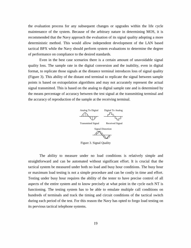
Even in the best case scenarios there is a certain amount of unavoidable signalquality loss. The sample rate in the digital conversion and the inability, even in digitalformat, to replicate those signals at the distance terminal introduces loss of signal quality(Figure 3). This ability of the distant end terminal to replicate the signal between samplepoints is based on extrapolation algorithms and may not accurately represent the actualsignal transmitted. This is based on the analog to digital sample rate and is determined bythe means percentage of accuracy between the test signal at the transmitting terminal andthe accuracy of reproduction of the sample at the receiving terminal.
Analog To Digital
Received Signal
Signal Distortion
Transmitted Signal
Digital To Analog
The ability to measure under no load conditions is relatively simple andstraightforward and can be automated without significant effort. It is crucial that thetactical system be measured under both no load and busy hour conditions. The busy houror maximum load testing is not a simple procedure and can be costly in time and effort.Testing under busy hour requires the ability of the tester to have precise control of allaspects of the entire system and to know precisely at what point in the cycle each NT isfunctioning. The testing system has to be able to emulate multiple call conditions onhundreds of terminals and track the timing and circuit conditions of the tactical switchduring each period of the test. For this reason the Navy has opted to forgo load testing onits pervious tactical telephone systems.
Figure 3. Signal Quality

20
THIS PAGE INTENTIONALLY LEFT BLANK

21
III. TELEPHONY BASED TACTICAL SHIPBOARD COMMUNICATIONSYSTEMS
A. TACTICAL TELEPHONY
The primary function of any voice communication system is to provide a means ofconnecting communications services from one communications network terminal (NT) toanother. This is further expanded in modern voice communications by regulatingadditional services, depending on the class a service and classmarks. This service allowssubscribers to place and receive multiple concurrent calls by providing each networkterminal functionality to adequately service all calls. Tactical terminals must provide non-blocking services allowing as many connections to as many terminals as the operatorrequests up to the limit of the class of service.
The tactical telephone system needs to provide a means to apply and managevoice over the network while, at the same time, providing ongoing functionality over thelegacy LAN. The core of the new network based tactical system is the existing shipboard-based LAN. It replaces the existing AN/STC-2(V) tactical switch infrastructure and theexisting adjunct administrative telephone system. The LAN based system is a computercontrolled distributive software based architecture. The proposed system needs to be ableto satisfy tactical operation requirements as well as administrative functions (Figure 4).The system will have auto attendant, call forwarding, net and conference calling, voicemail, computer telephony features.
The proposed tactical system is entirely encompassed within a shipboard LANsystem. The system uses the multimedia capability of the network to deliver voice to theshipboard sailor using the existing data infrastructure. In the basic configuration thePOTS analog 2500 network terminals are connect to a telephony enabled interface whichis then multiplexed and sent over a connection to the telephony server via the commandinterface. During the call setup procedure the telephony server connects the requestingand requested network terminals by way of the bi-direction audio input and output. Thetelephony server continues to communicate with the POTS interface using the commandchanneling.
The implementation of the system needs ensure quality of service (QoS) alongwith data on a common set of wires to each user. Voice and data are routed over the same

22
wiring through any number of industry standard switches. Voice is delivered overspecifically reserved, dynamically allocated virtual circuits within the LAN fabric.Telephony is enabled for each user via voice enabled network interface firmware. Thisunique architecture enables the system to have a mixture of networks and telephonyservices over the existing infrastructure. This architecture permits a scaleable solution andallows the ship to gradually convert to the high speed network architecture while stillusing the existing PBX system.
Idle
Answer
ShortBusyBusy
Tone
DialTone
Trunk Busy
Off
Hoo
k
TrunkLine
PSTN
On
Hoo
k
Dia
l “5”
InternalCall
Ring
Busy
Con
nect
On Hook
On
Hoo
k
TimeOut
Dial “9”
Dial (4)
Not Busy
Delay (10s)
On Hook
Trunk AvailableDial (7/11)
Message
Inva
lid N
br
Polling
1. Threat Description
There are several unique shipboard threats that need to be taken into considerwhen developing any shipboard electronics system. Systems residing on a LAN thatconnect external to the ship pose additional caveats. All these conditions have to beaccounted for they have to be tested against government approved standards before theycan be considered candidates for implementation.
Electronic systems in use today minimize power consumption and provide aminimal amount of radio wave interference protection. It requires only a minimal amountof external electronic interference to disrupt the system’s internal signaling. The hull ofthe ship provides a measure of protection against external electronic interference fromidentified hostile forces. A significant number of disruptive forces emanate from causesinternal to the ship. These disruptive forces can be benign in their origin or they can be
Figure 4. State Diagram For Phone Line

23
an inadvertent attempt by friendly forces that causes signal failure. All but a few of thesethreats can be safeguarded against to a relatively high degree of confidence using lowtechnical safeguards. The greatest threat, and the most difficult to guard against, is thefriendly force member who is predetermined to violate the built in precautions. Thetradeoff becomes: how much liberty over system and configuration control should bebuilt into the system and how to modify and retain configuration control over thoseaspects the ship’s force does not retain control over.
Because the system is designed to reside on the ship’s network backbone andcoexist with other COTS systems additional security risks are apparent. Denial ofservices, whether deliberate or inadvertent from internal or external sources, form thegreatest possibility of system failure. This type of attack is relatively simple toaccomplish and can be mastered from external sources with very little informationregarding the internal operations of the system.
Improper system configuration can cause excessive chatter on the networkcausing, in effect, the same denial of services as if it were an external attack on thesystem. Prevention of this type of denial of services can only be limited by a highlytrained and competent work force that routinely checks the system for identifiableproblems and is knowledgeable in how to quickly isolate the offending equipment andreconfigure the system on the fly during critical situations.
Future requirements for the tactical voice communications system is thecombining of secure and non-secure communications over the same voicecommunications system. This presents additional security requirements that need to beconsidered when designing the system. Methodologies employed in digitalcommunications allow signals to couple on top of another that does not diminishcommunications capabilities or signal quality. This allows inadvertent coupling of signalsthat are in relatively close proximity to each other. Within the confines of the ship thiscoupling has minimal effect on security. If the communications is transported off the shipby any method, there is a significant possibility the non-friendly sources can receive thesignal and decipher not only the original but also, the coupled signal. Care needs to betaken to ensure that non-encrypted classified signals do not come in close proximity toany system that has not been tempest approved.

24
2. Interoperability
Interoperability is the ability to utilize network terminals (Table 6) with differingfeatures and functionality from varying manufactures and has them plug and playthroughout the communications system employing a common interface and protocolstandard. Interoperability between current, next generation, and commercial phonesystems only exist within a limited scope of communication environment. Thefunctionality of the network terminal is interdependent on the operations of the PBXswitch. This makes most network terminals on any system proprietary to that system.Interoperability becomes particularly important as the number of service personnel aboardthe ship is reduced and the technology training of those personnel is reduced to a minimalacceptable level.
Points of clearly defined demarcation are the primary methodology of successfullyintegrating competing manufacture’s equipment. Eliminating the interdependence of thenetwork terminal to the transport medium would create a system where functionality isdesigned network terminal to network terminal. The functionality of the inter-linkingnetwork would encapsulate the communication signal and primary transport medium andconvey the data across the network. The receiving network interface would then performthe reverse process, creating a virtual point to point communication.
Developing the voice over LAN system using the ISDN as the primary interfacewould allow the inclusion of the major terminal types with only software as the principaldifference. The stacks, protocols, and physical layer of the interfaces would remainidentical across the different network terminals. The ideal development would useidentical firmware for each of the network terminal interface with either a manual orsoftware configurable determination.

25
Terminal Type Usage Interface Type
ISDN
Commercial AdministrativeISDN
2B + D
Secure Terminal Equipment AdministrativeISDN
2B + D
Harsh Environment Partial Tactical1B
ISDN
Below Decks Full Tactical2B + DISDN
ANALOG
POTS 2500 Handset AdministrativeAnalog
Low Impedance
Jack Box TacticalAnalog
Low Impedance
Sound Powered TacticalAnalog
Low Impedance
Announcing System TacticalAnalog
Low Impedance
Radio TacticalAnalog
Low Impedance
3. Scalability
Established PBXs switches have limitations in their scalability. Expanding beyondthe hardwired limits of the switch usually requires procurement and integration ofadditional switches at a significant cost increase. As telephony requirements increase, thesystem should not require massive replace upgrades as are common with traditionalPBXs. The network components should provide for increased requirements without amajor impact on the existing system.
Table 6. User Network Terminals

26
Any telephony component establishing communications on the same telephonesystem network should be designed so that it is aware and uses the same configurationsystem. Although only one component may be involved in establishing the call, severalcomponents may exists and operate on a load sharing relationship. This will also allowfor system redundancy and granularity. This will allow resources to be added at anylocation in the network. System requirements can be located at the most appropriate placein the network. The mixed scalable architecture needs to permit organizational flexibilityto allow for deploying various types of telephony systems while still retaining existingLAN components.
4. Granularity
The load sharing and co-processing abilities, the proposed development should bedeveloped and implemented in a granular methodology. The development of features,wherever possible, should not be developed requiring co-dependency on existing features.The telephony network components need to be distributed across the ship on as requiredby each location. This requires each controlling aspect of the system to be aware of allother peer level controllers. Rather than a hot standby type of implementation, eachcontroller or telephony server, is required to shoulder an ongoing portion of the load. Asthe system increases in size, additional servers can be placed online, configured andautomatically assume the proper balance of the services.
5. Redundancy
The shipboard tactical telephone system requires that the system be available foruse at all times. The existing tactical switch has benefited from decades of use andsupport. Reliability and redundancy should be built into the system. The system does notrequire centralization and should be designed to eliminate any single point of failure. Thenetwork supporting the development needs to be inherently fault tolerant, providing arobust telecommunications system. Any system replacing the current tactical phonesystem needs to meet or exceed the current reliability standards. The system should bedesigned to avoid architectural bottlenecks.

27
6. Standards-Based Telephony
Except for a limited number of network terminals and certain features of interfaceinteroperability, most PBX switches do not maintain any interoperability betweencommercial systems. Some of this has to do with operational, functional or othertechnical features, but most of it is economic based reasoning. When a system isstandards based then manufacturing of components becomes a lowest bidder effort and itbecomes difficult for the manufacture to recover development costs and to make asignificant profit. These are the same reasons why the Navy should base its developmentof industry standards and only incorporate COTS equipment that does follow standards.
The incorporation of standards base in the development of the system allows forthe integration of multi-vendor equipment across the switch. This allows the Navy tofocus the development on equipment performance specifications and not on the internaldetailed operations of any specific equipment. This type of development is based on theassumption that there are several developers that manufacture any specific piece oftechnology. Because the Navy has unique requirements and a limited market, there areinsufficient resources within industry to totally support COTS or commercial standardsbased development. The most effective approach is a hybrid system that employsindustry standards and COTS, when the equipment is commercial available, andinternally developed components that are phased out as commercially availablereplacements become available.
B. SYSTEM PERFORMANCE CAPABILITIES
There are network voice communication devices in existence today that performwell enough to be given consideration for possible inclusion as administrative voicesystems. However, many additional considerations need to be taken into account whenmaking determinations for tactical communications. End to end performance capability iswhat distinguishes the abilities of a tactical audio communications system from anadministrative system or the hobbyist’s ability to communicate over the internet.
In functionality, they all perform relatively the same; they all pass audiofrequencies from one point to another. It is the time and effort required accomplishingthe task and the quality of service of the transmitted voice that determines what type ofsystem has acceptable levels of reliability and performance. Even though the system is

28
used and does have strictly administrative features, its primary function is during highlycritical shipboard situations. By ascertaining the liability if the desired objectives are notobtained makes the level of determination. Since safety and the value of human life areparamount, the ability of the system has to meet a significantly higher level ofperformance standards available within the industry.
1. Traffic
In the existing telephone system, traffic is limited by the ability of the call controlprocessor to service each terminal. Even when a terminal is not connected to the PBX, theCCP reserves a time slot within the computing cycle to service any, non-existing, request.Because the current technology is time sliced rather than interrupted driven, the ability ofthe CCP to service incoming requests is severely limited. This limitation is marginallycircumvented by physically load balancing the forward and aft PBX switch processors sothat neither is overloaded during critical events.
The shipboard LAN is a shared resource and there is limited ability to preciselydetermine the exact load of any aspect of the system at any given time period. In the newdevelopment the voice over LAN system has to have the ability to perform non-disruptivetransfers of network terminals load and functions located on the LAN within specifiedtime allocations. This may include design criteria based on load balancing due to aterminal’s physical placement in a high or low utilization area. This determination ismade during busy hour when the system has to service requests from a maximum numberof terminals. Because it is difficult to determine the exact amount of effort required by thecontrolling functions at any give time, more comprehensive traffic requirements fordetermining load sharing and parallel processing efforts needs to be implemented. Thesystem should be designed such that all possible combinations of requests for all trafficrequests and services from all terminals located within the LAN have to be serviced bythe system within the allocated bandwidth and time limit. If the system is unable tooperate a minimum level of performance, the network needs to have the ability todetermine priority of all the communications within its domain and reduce or eliminatecommunications whose priority fall below the maximum bandwidth utilization ability.

29
2. Blocking Criterion
Because of the tactical aspect of the switch, no service request from any tacticalnetwork terminal can be blocked at any time as a result of the switch being too busy toprocess the call or because of unavailable resources within or between switches. Althoughthis is a correct statement, the implementation of the system has shown this to beimpractical. The physical layout of the terminals aboard the ship limits the number ofinter-switch connection requirement during any tactical requirement. If the switch getsoverloaded with incoming calls the system merely queues any incoming requests forservice until processing time becomes available to service that request. The currenttactical system can only process sixteen concurrent requests. During busy hour this canmean that, from the time the last digit is pressed until forward ring, it can take up to fourminutes to complete a service request. Although this is not a likely occurrence, the factthat it is an acceptable specification shows the system’s blocking limitations.
LAN based telephony has a similar problem that needs to be overcome if it is tobe a viable contender in the communications market. LAN based data communications isbest effort driven technology. If the communications channel becomes too congested withcommunications, it just buffers data transfers until the channel becomes more available.While delays in traffic flow have minimal effect in data communications, in audiocommunications it can have a major impact.
The requirements for the tactical system requires there be at least two switchservers providing terminal services as well as network call setup and take down. Thesystem is designed where each switch has an additional hot backup. This creates a systemthat has four full switches where only two are active at any one time. Rather than have ahot standby system, as is currently implemented, the telephony servers should have fouror more active load sharing call processing switches. If one of the switches fails the othershould have the ability to handle the entire load. The design should also permitgranularity of the system by allowing additional switches to be added at strategic parts ofthe system thus further reducing average load requirements while allowing criticalnetwork segments to work in total isolation if required.

30
3. Call Setup Time / Setting Up a Connection
Call setup is the ability of the telephony server to receive data from the requestingnetwork terminal and setup a connecting circuit across the LAN to the receiving networkterminal (Table 7). Call setup is a telephony server function that accepts digits from therequesters touch tone pad and translates them into a network address. The telephonyserver has to validate the rights of the requesting and receiving network terminals as wellas negotiate the privileges they have to utilized resources on the network.
The response of the telephony server to requests from the network terminals doesnot have a real time response criterion, but does have to perform a maximum number ofrequests within a specified period of time. Most of the time request for services from thetelephony server will be minimal. There are peak periods of time when an overwhelmingnumber of users will attempt to request services. During this peak period call processingand setup of the services has to appear to the user to be in real time. The telephony servershould be able to handle up to thirty concurrent network terminal requests without anynoticeable delay in response. Because it is expected that a first-in-last-out interrupt drivenstack will be required to service requests, as the number of concurrent requests forservices exceeds the available real time processing cycle, a noticeable delay of a fewseconds will occur. If the delay becomes excessive, elements of the granularly of thesystem design should be implemented.
4. Automatic Route Selection
Automatic route selection is the ability of the network controllers to determine theshortest time path for the voice data to transit across the network. The network controllerscontinuously monitor the network for bottlenecks, circuit failures, or other signaldegradation causes and has the ability to dynamically reroute traffic. The LAN basedtelephony system has to have the ability to vary the actual route of any aspect of thecommunication and can vary with each instance of the call. This allows the system tocompensate for network changes, circuit availability, and system failures.
The LAN based system needs to maintain, at least, a single layer of redundancyonce the communications is established. If for any reason the communications channelshould fail the system should provide hot cut over capabilities. The cut over of the NTshould be transparent to both the NT user and system administrator. There are several

31
types of networks available in the commercial market that provide hot cut over, or theequivalent, services as an integral part the network environment. Unfortunately, the mostpopular network employed in the Navy does not have automatic fault detection andcorrection.
The initial call signaling command to set up the dedicated circuit within the LANis sent to the LAN controller from the telephone server when the receiving terminal goesoff-hook. Once the call is established between the network terminals the LAN controlleris responsible for maintaining and making any circuit changes to the connection until allterminals go on-hook.
5. Warm Reset Time
The warm reset is defined as the time it takes for the system to reach fullyoperational condition from the time power is first applied to all components of thesystem. This is how long it takes the system after a complete system shutdown to rebootand reestablish all circuit connections to the last know good condition.
The warm reset time is based on the assumptions: that the ship is in battleemergency or otherwise critical situation; that the tactical voice communication systemhas lost part or all operational ability do to events external to the system; that re-establishing communications is paramount to the safety of the ship’s force, that any delayin voice communication could result in the loss of life or property; and that the ship’soperational capacity in a critical situation. This presupposes that all system componentsare operational and that all other tactical environmental conditions have been met.
The reactivation of the system requires the telephony server(s) to maintain anactive database of all connections as they are setup and taken down. When the systemgoes off line if there is an appropriate shut down procedure that is annotated within thesystem database. When the system is re-activated it checks the status of the last knowncondition of the system. If the system terminated in a non-standard state the re-bootprocedure assumes that a threat conditional exists and reprioritized boot proceduresgiving preference to critical communications circuits over standard maintenance or housekeeping procedures.

32
The reboot process reestablished all network terminal connections to their lastknown good condition. Circuits will not be reestablished for those network terminals thathave gone to the on-hook status subsequent to system shut down. There is a window oflost opportunity between the time a network terminal goes off-hook and before the circuitis established. If the system shuts down during this time period, the terminal connectioninformation is deleted and the call is treated as a terminated attempt. The attempt has tobe re-initiated from its inception by going on-hook and re-establishing the call.
Traffic Description Criteria
Call BusyThe number of telephones unable to make orreceive a call because of network bandwidthlimitations
No more than 0%
Call InitiationThe delay from going off-hook to the receipt ofthe dial tone.
3.0 seconds
Call CompletionDelay from the last digit dialed to ring of thereceiving phone.
0.5 seconds
Call BlockingThe number of phones unable to completed acall because of a control subsystem error, falseswitching or erroneous station signal.
0.001
Call MisroutedThe mis-routing of a call due to hardware orsoftware error.
106
System FailureWhen 15% or more of the phones do not havethe ability to originate or receive calls.
0.999995
Table 7. Busiest Hour Traffic Handling

33
IV. INTEGRATING TACTICAL VOICE OVER THE SHIPBOARD NETWORK
A. OVERVIEW
Deployment of voice over data networks is at the heart of the convergencerequirement. The new system must not only provide an effective alternative to circuitswitched telephone systems, the consolidation must also save shipboard time andresources. The implementation should be seamless and must incorporate the traditionalPBX functionality across a ship-wide local area network. To the end user, the operationand functionality of the LAN based tactical telephone system must be identical to thecurrent tactical system.
The system must incorporate all current external trunk line access and provideservice to the tactical phones, emerging technology and traditional POTS analog networkterminals. The new system should incorporate functionality not currently incorporated inthe tactical PBX such as system administration and management, voice mail, callforwarding, call waiting, and other feature commonly available in commercially PBXs.
The tactical telephone is required to co-exist on the network infrastructure withother tactical and non-tactical systems. Because of the nature of the infrastructure thisposes significant security risks not normally associated with stand-alone systems. Toovercome this limitation the communication system needs to provide a trustedrelationship between the communication terminals and the public accessed network.
B. BROKERING
In traditional telephone systems the telephone switch acts as a central processorunit (CPU) through which all communications control commands are processed. Theprocessing time of the CPU is evenly divided between each of the logically connectedterminals. Each terminal is allocated a maximum amount of processing time and nosingle terminal can surpass its time allocation. Any time slice not fully utilized by therequirements of the terminal is cannot be reallocated back for system administration,“house keeping” and other non-time critical functions. This method of communications

34
provides the system with direct control over the communications channel of each andevery terminal on the system and controls all resources within the telephone network.
In voice communication over a shared networks, each terminal has to have theability to directly communicate with other network terminals located within the networkand to external PBX switches through the trunk-line interfaces. The system has to havethe ability directly address the location of a given terminal based on a phone number orthe terminal has the address of a centralized server that provides this database services(Figure 5). This trinary communications interface requirement is located within the localdomain of the shipboard network and has to provide a proficient method for meteredservices. Because the system will reside on a network, where it has to compete forresources and services with users other than the tactical telephony system, a method ofresource brokering needs to be established to allocated public assets, determine interfaceprotocol compatibility, enforce class markings within the terminals, prevent unauthorizedterminals from gaining access, and prevent denial of services attacks. The combination ofthe trinary interface and the telephony server, through the network infrastructure, providethe fundamental control and communication features of the telephony based tactical voicecommunications system.
Network
����������
POTSClient
Interface
�����
�����
Broker
TacticalClients
Agent
J-BoxClient
InterfaceSound Powered Net
AnalogClient
Interface
Figure 5. Brokering Management

35
C. RESOURCE CONTROL AND ALLOCATION
The tactical voice communications system will be deployed in an environmentwhere the resources are shared and available to users of unknown origin. The system hasto have means of controlling owned assets while preventing non-affiliated co-residingusers from gaining access or preventing legitimate users from gaining access to assets.The system also needs to have a system of brokering shared resources in such a fashionthat minimum performance standards are met for both the tactical communication systemand other critical users operating within the environment. The problem is furthercompounded because the owned resources are physically separated from each other andlogically connected by the shared, non-owned, resources.
The optimum implementation would be using a broker between tactical telephonyresources and employing agent for gaining control common resources. When a tacticalnetwork terminal is idle it competes for network resources at the same level as any otheruser.
One of the first resources is a dial tone (Figure 6). It is the function of thetelephone server to ensure the request for services is coming from a legitimate source.This is not a highly time critical requirement, but does have a finish within limitation of afew hundred milliseconds. For the terminal operator this is the dial tone response, for thesystem this is when the terminal requests permission to access resources within thetactical telephony system. This exchange sequence identifies the network terminal to thebroker who then verifies it against an internal database as a legitimate resource. At thistime the broker authorizes the terminal to request use of tactical resources. This is not anauthorization to use tactical communications resources, but an authorization to requestthe use of NT resources. Using a broker to identify the tactical resource prior to usagepermits the system to provide administrative functions and prevents non-tactical usersfrom accessing the system or effecting denial of services.
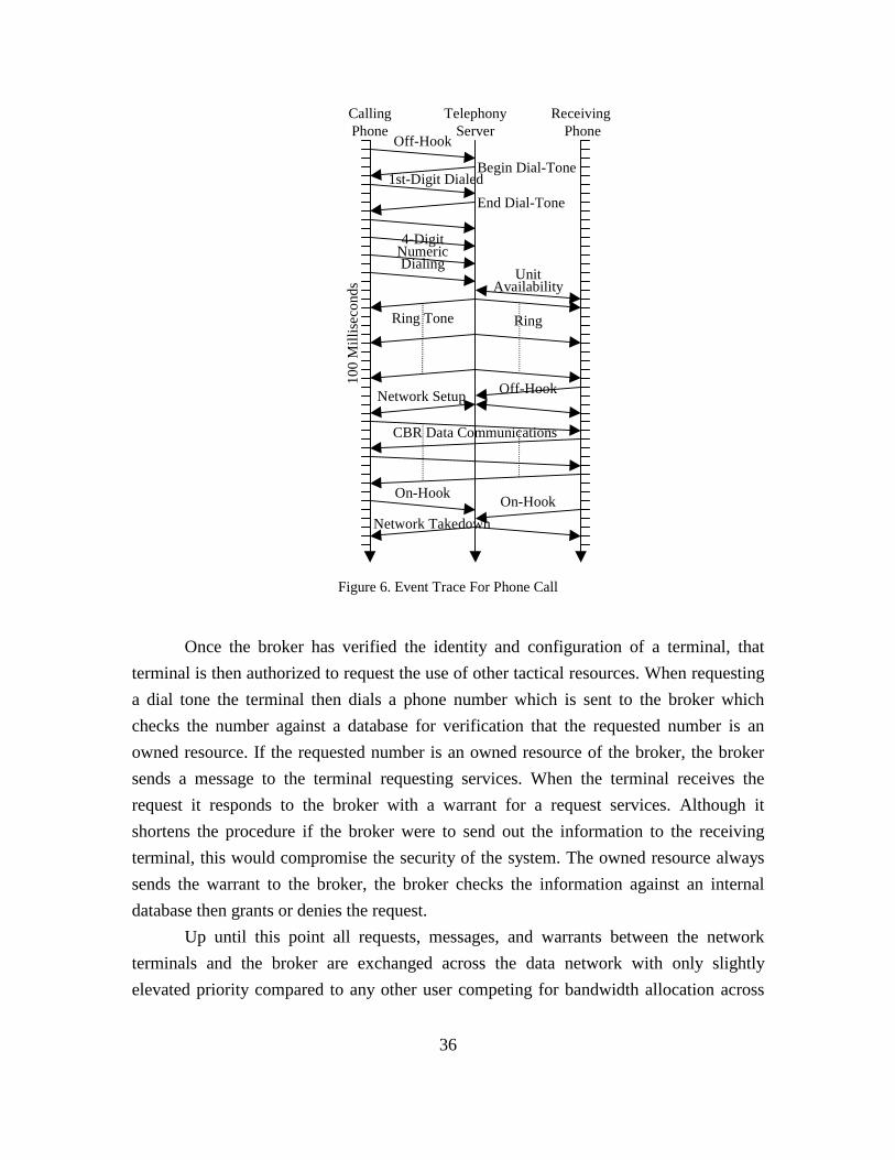
36
CallingPhone
Receiving Phone
TelephonyServer
Off-Hook
Off-Hook
Ring
Network Setup
CBR Data Communications
On-Hook
Network TakedownOn-Hook
4-DigitNumericDialing
1st-Digit DialedEnd Dial-Tone
Begin Dial-Tone
100
Mill
isec
onds
UnitAvailability
Ring Tone
Once the broker has verified the identity and configuration of a terminal, thatterminal is then authorized to request the use of other tactical resources. When requestinga dial tone the terminal then dials a phone number which is sent to the broker whichchecks the number against a database for verification that the requested number is anowned resource. If the requested number is an owned resource of the broker, the brokersends a message to the terminal requesting services. When the terminal receives therequest it responds to the broker with a warrant for a request services. Although itshortens the procedure if the broker were to send out the information to the receivingterminal, this would compromise the security of the system. The owned resource alwayssends the warrant to the broker, the broker checks the information against an internaldatabase then grants or denies the request.
Up until this point all requests, messages, and warrants between the networkterminals and the broker are exchanged across the data network with only slightlyelevated priority compared to any other user competing for bandwidth allocation across
Figure 6. Event Trace For Phone Call
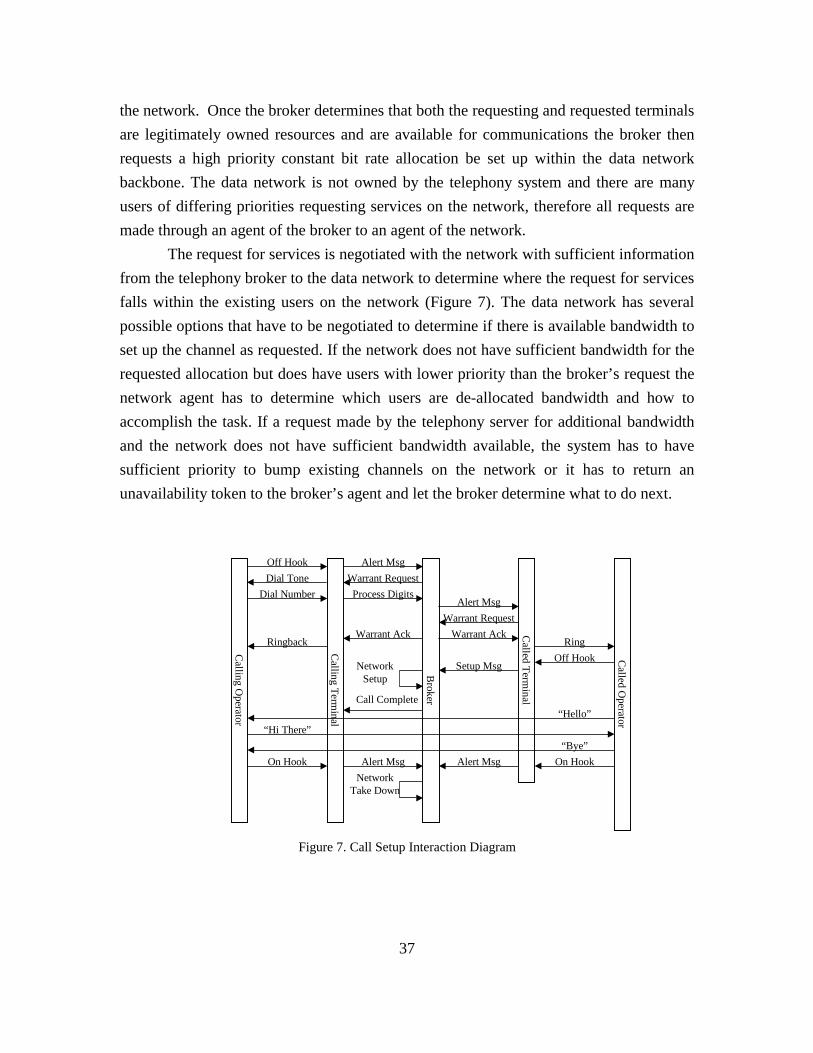
37
the network. Once the broker determines that both the requesting and requested terminalsare legitimately owned resources and are available for communications the broker thenrequests a high priority constant bit rate allocation be set up within the data networkbackbone. The data network is not owned by the telephony system and there are manyusers of differing priorities requesting services on the network, therefore all requests aremade through an agent of the broker to an agent of the network.
The request for services is negotiated with the network with sufficient informationfrom the telephony broker to the data network to determine where the request for servicesfalls within the existing users on the network (Figure 7). The data network has severalpossible options that have to be negotiated to determine if there is available bandwidth toset up the channel as requested. If the network does not have sufficient bandwidth for therequested allocation but does have users with lower priority than the broker’s request thenetwork agent has to determine which users are de-allocated bandwidth and how toaccomplish the task. If a request made by the telephony server for additional bandwidthand the network does not have sufficient bandwidth available, the system has to havesufficient priority to bump existing channels on the network or it has to return anunavailability token to the broker’s agent and let the broker determine what to do next.
Calling O
perator
Calling Term
inal
Broker
Off HookDial Tone
Dial Number
“Hi There”
On Hook
Alert MsgWarrant RequestProcess Digits
Ringback
Called Term
inal
Called O
perator
Alert MsgWarrant Request
Warrant AckRing
Warrant Ack
Off Hook
Call Complete
NetworkSetup
Setup Msg
“Hello”
“Bye”On HookAlert Msg Alert Msg
NetworkTake Down
Figure 7. Call Setup Interaction Diagram
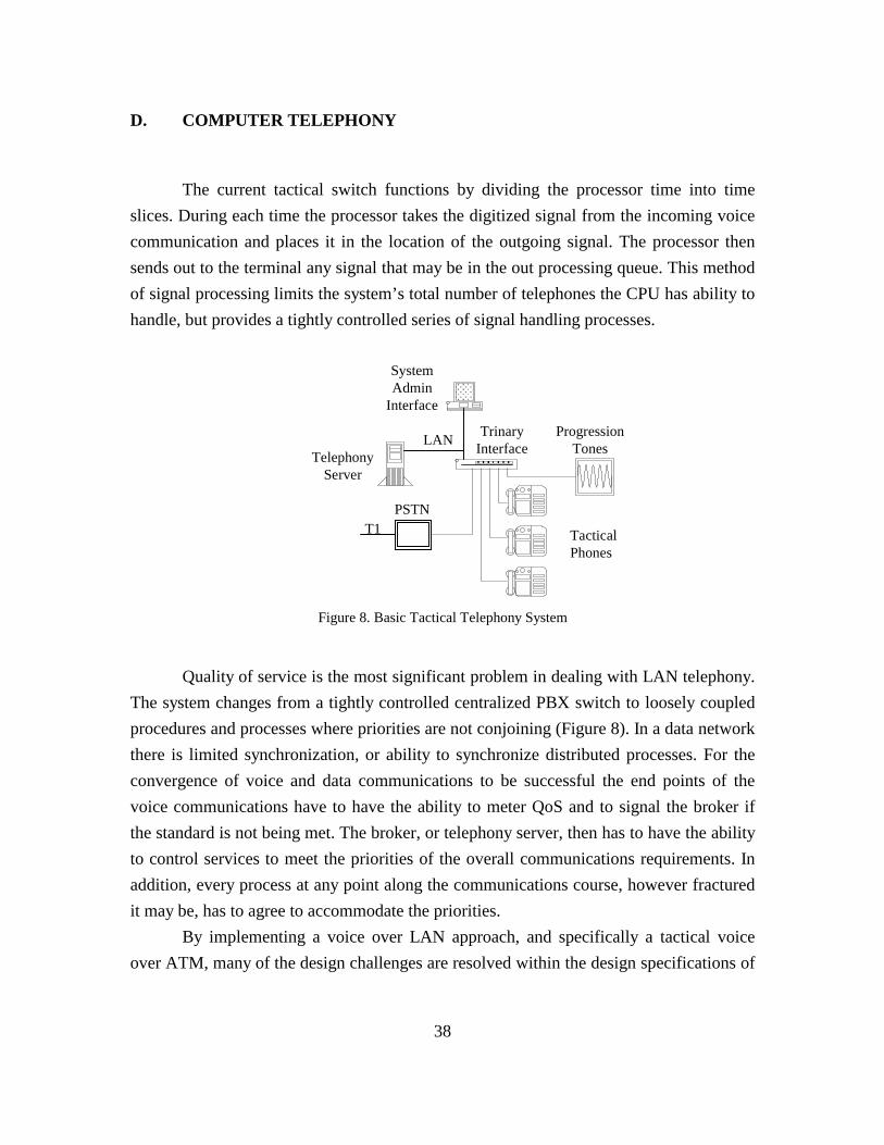
38
D. COMPUTER TELEPHONY
The current tactical switch functions by dividing the processor time into timeslices. During each time the processor takes the digitized signal from the incoming voicecommunication and places it in the location of the outgoing signal. The processor thensends out to the terminal any signal that may be in the out processing queue. This methodof signal processing limits the system’s total number of telephones the CPU has ability tohandle, but provides a tightly controlled series of signal handling processes.
T1
����������������������������������
TacticalPhones
TrinaryInterfaceLAN
TelephonyServer
PSTN
ProgressionTones
��������������
SystemAdmin
Interface
Quality of service is the most significant problem in dealing with LAN telephony.The system changes from a tightly controlled centralized PBX switch to loosely coupledprocedures and processes where priorities are not conjoining (Figure 8). In a data networkthere is limited synchronization, or ability to synchronize distributed processes. For theconvergence of voice and data communications to be successful the end points of thevoice communications have to have the ability to meter QoS and to signal the broker ifthe standard is not being met. The broker, or telephony server, then has to have the abilityto control services to meet the priorities of the overall communications requirements. Inaddition, every process at any point along the communications course, however fracturedit may be, has to agree to accommodate the priorities.
By implementing a voice over LAN approach, and specifically a tactical voiceover ATM, many of the design challenges are resolved within the design specifications of
Figure 8. Basic Tactical Telephony System
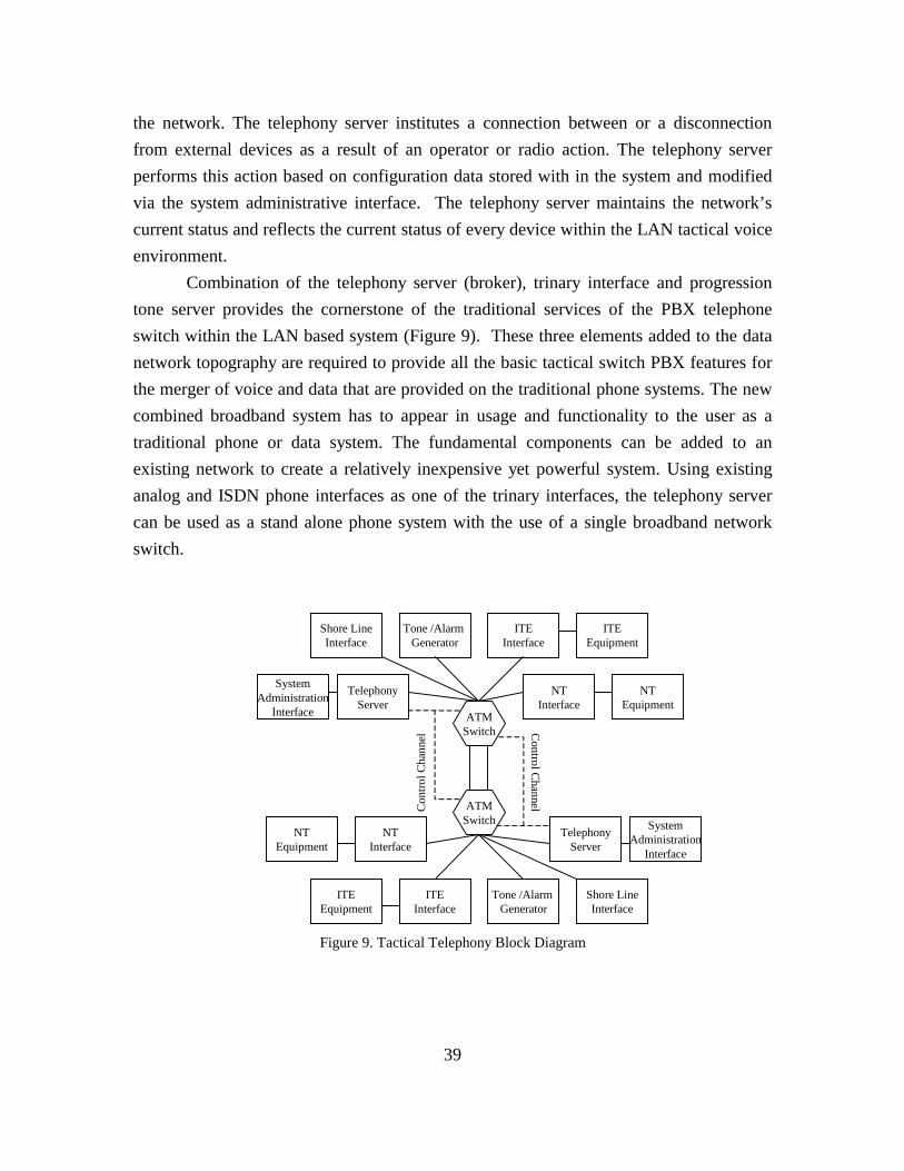
39
the network. The telephony server institutes a connection between or a disconnectionfrom external devices as a result of an operator or radio action. The telephony serverperforms this action based on configuration data stored with in the system and modifiedvia the system administrative interface. The telephony server maintains the network’scurrent status and reflects the current status of every device within the LAN tactical voiceenvironment.
Combination of the telephony server (broker), trinary interface and progressiontone server provides the cornerstone of the traditional services of the PBX telephoneswitch within the LAN based system (Figure 9). These three elements added to the datanetwork topography are required to provide all the basic tactical switch PBX features forthe merger of voice and data that are provided on the traditional phone systems. The newcombined broadband system has to appear in usage and functionality to the user as atraditional phone or data system. The fundamental components can be added to anexisting network to create a relatively inexpensive yet powerful system. Using existinganalog and ISDN phone interfaces as one of the trinary interfaces, the telephony servercan be used as a stand alone phone system with the use of a single broadband networkswitch.
ATMSwitch
TelephonyServer
ATMSwitch
Tone /Alarm Generator
ITEInterface
NTInterface
ITEEquipment
NTEquipment
TelephonyServer
NTInterface
Tone /Alarm Generator
ITEInterface
NTEquipment
ITEEquipment
Con
trol C
hann
el
Control C
hannel
SystemAdministration
Interface
SystemAdministration
Interface
Shore LineInterface
Shore LineInterface
Figure 9. Tactical Telephony Block Diagram

40
1. Telephony Server
The telephony server along with the trinary interface and progression tonegenerator provides the services traditionally supplied by the PBX. These three devices aretightly coupled in their operations, but are required to interface over a loosely coupledLAN. Most of the services provided by the telephony server are non-time critical. Thereare specifications for the server to prove certain services within a maximum allocatedtime, but variances of up to a few seconds are acceptable.
Unlike the traditional telephone system, where there is a single server allocatingall resources, a combined system will have several classes of non-related users sharing acommon infrastructure. Because it is not a closed system, it is assumed that most of thecommon resource users will be unidentifiable to the telephony portion of the system(Figure 10). Before any user is allowed to gain access to the system the telephony serverhas to verify authenticity of the network terminal. The authentication is required toprevent users of the network of lower access rating to tax system resources beyond theirallocation. The telephony server then brokers the network terminal’s request for servicesover the broadband and local area networks.
In addition to authentication and classification, all users of the system have to beprioritized to allow an overarching LAN manager to deny, delay or reroute servicerequests of all system users. The telephony server works in conjunction with themanagement control features of the network resource manager interact in a broker clientrelationship to provide these services. This allows the telephony server to provide controlfeatures that monitors the quality of service for each of the active network terminals andsends requests to the network for reallocation of resources when QoS is not being met.
One of the primary functions of the telephone server is to provide dialing servicesto the network terminal. The dialing services converts the instructions given through thenetwork terminal’s human interface panel into commands understood by electronics ofthe system. The converse is also true: dialing service converts the instructions andcommands related to the electronics of the system into signals understood by the humanoperator. Dialing services requires the inter-linking of the progression tone generator tothe user’s terminal across the LAN. It is the progression tone generator that provides thehuman interface functionality conveying the status of the telephone system.

41
The most critical aspect of the telephony server is the ability to monitor andcontrol the network terminal’s quality of service. The ability to monitor and control QoSfor the terminal requires the trinary interface to observe signal quality as it is received.Because the trinary interface has no ability in itself to exercise control over the network, ithas to notify the telephony sever of the conditions of the incoming signal. The telephonyserver then has to negotiate or broker with the network manager for reallocation of thenetwork resources. The telephony server has to have the ability to interface with allnetwork terminals in a near real time basis when brokering the bandwidth allocationbetween the network terminals.
Server
Web
Server
TrinaryInterface
FileServer
Host
ATMFDDI GBit
10/100 BaseTTokenRing
DigitalN
T
AnalogN
T
TrunkPort
ISDN
POTS
T1 / E1
Netw
ork Broker
TelephonyServer
System A
dmin
2. Trinary Interface
The trinary interface (Figure 11) is the key feature that allows the networkterminals with none-LAN interface standards to communicate with other user terminalsutilizing LAN resources. The trinary interface along with the telephony server is whatprovides the services over the LAN based telephony system that is normally provided inthe traditional telephone system. When PBX telephone goes off-hook the switch sendsout a dial tone to the terminal. There is no equivalent in the LAN based systems for
Figure 10. Voice And Data Convergence Over Broadband Block Diagram

42
providing progression tones and other services normally expected in phone systems. Thetrinary interface is the means by which the system can provide these services.
Audio Out
Command Out
Audio In
DAC
ADC ATM Out
ATM In
Command In
Interfaces to the LAN receives signaling in data format, usually asynchronousnon-real time form, and have to re-order packets. The packets are then stripped of headerinformation and the remaining data is sent to the network terminal interface. The terminalinterface buffers the data, adds frame timing and repackaging the data depending on theterminal type. The synchronous packet is then sent out to the network terminal. Thetrinary interface has the ability to tell the telephony server that bandwidth requirementsare not being met and to request the LAN to shut off non-essential services of lessorpriority. This give the trinary interface the capacity to determine if quality of servicestandards are being realized and to signal the telephone server if they are not.
One of the primary functions of the trinary interface is the ability to characterizeand route commands coming from the network terminal to the proper destination. Thetrinary interface has to know when to send commands to the telephony server or as dataout to the network interface. Many of the commands coming from the network terminalsare indistinguishable in form from data to be passed across the network or commands tobe passed to the telephony server. Some commands are always routed to the telephonyserver, other commands are only routed to the server during specified times of thecommunications cycle. The primary distinction is the nature of the command and at whattime during the calling cycle they occur. The trinary interface has to be able to discern thedifference and properly route the command.
The trinary interface will require the network terminals to negotiate an acceptableformat for terminals of different communication format types (Figure 12). In conventionalsystems this is not a major issue because all in coming call formats are normally
Figure 11. POTS Trinary Network Interface

43
converted into a common format at the switch then reconverted to the outgoing channelsformat before being sent to the receiving network terminal. Because there is no commonswitching in the proposed system, the ability to negotiate a common format betweennetwork terminals is placed on the trinary interface. The classification communicationbetween the NTs has to occur prior to establishing transmission in order for the telephonyserver to request from the network broker the required LAN resource allocation.
����������������
������������
TacticalPhones
ISDN TrinaryInterface
TelephonyServer
PSTNT1
������������������������������
BroadbandSwitch
����������������
LANServer
BroadbandEthernetSwitch
����������������
����������������
Ethernet
ProgressionTones
SystemAdmin
Interface
�������������
POTSTrinary
Interface
������������Trunk Trinary
Interface
POTSPhones
WorkStations
ISDN
48 Volts
�������������
Special AppsTrinary Interface
AnnouncingSystem
Radios &Satellites
Placement of the trinary interface is critical to maximize the benefit of a commondata and voice infrastructure. By integrating at the base of the network terminal thetrinary interface with the user terminal allows the system to deploy a common cable plantand will allow maximum interaction with the telephony server to ensure QoS within theinterconnecting network. Due to non-software related constraints it may be required toplace the trinary interface in a physical location other than next to the user terminal. This
Figure 12. Network Centric Tactical Telephony System

44
creates unique wiring specifications for the data and voice terminals, but is still a viablesolution.
3. System Administration Interface
The system administrator interface (SAI) is how the system operator monitors andcontrols the functionality of the telephony server, network terminals, and otherconfigurable system devices. The SAI is how the system administrator configures thetelephony server and programs all network terminals. The SAI also assists the systemadministrator in diagnostics of the system when automated diagnostics are unable todetect and notify the system administrator of the problem. The SAI is an independentlyoperated computer interface and is only employed for the configuration and monitoring ofthe system and does not impede operations of the system should the SAI become non-operational.
4. Internal Diagnostics Testing
An integral part of the telephony services is the ability to detect faults within thesystem and seamlessly reroute the call or switch to a hot standby backup. The system hasto be able to detect system faults as soon as they occur in order to prevent loss of sign orsignal quality. The system should also prevent false connections due to unpredictableevents as well as continuously validate all current connections. The auditing of theconnections can be preformed against a connection map that compares currentconnections against actual connections.
The system needs to perform on going tests of embedded software and hardwarein the external terminal interface cards, backplane I/O channels, within the networkterminals interfaces and other end equipment. No single point failure should cause a lossof more than ten percent of the total communication capacity. For subsystems whosefailure would cause a loss of more than ten percent of the system capacity, a hot backupor rerouting configuration should be employed. When an error or failure is detected thesystem should seamlessly disable any elements on the previously active component thatwould inhibit the proper operation of the switch. A normal course of development for the

45
backup scenario would be to have a primary control unit actively monitor the operationsof the active units and when an error is detected aggressively take control and shut downthe suspected defective unit and reroute any active signals.
The system should be designed in such a manner that all devices or sub-systemswithin the critical path of any tactical call can be hot swapped without the interruption ofany active call. For most devices the hot swappable ability will require that the power andsignals be applied to the card level components via the backplane or I/O interface. Thecomponent or subsystem being hot swapped should require a minimum of configurationsetup by the technician or operator. The technician should be able to place a device withinthe system and that device should have self-configuring ability by determining its locationwithin the system and reading configuration tables of adjoining devices.
When a fault is detected the system will notify the operator via a series ofnotifications or alarms based on the criticality of the failure. (A notification is simplyinforming the operator of a system condition that is not expected but does not affect theproper operation of the system.) Terminal equipment improperly identified within thedatabase that does not match the signal type expected from that terminal would be anexample of a notification. A minor alarm is when a sub-system fails to operate properlyand the subsequent outage is less than ten percent of the total capacity of the system. Amajor alarm is when the failure affects greater than ten percent of the total operationalcapacity which would normally require a hot standby to assume operations.
5. Hot Switchover
One of the more difficult software functions to implement on the tactical switch isthe hot cut over of any out of service equipment without disruption in service or loss ofcall connection. The primary method of determining system failure is by having the activestandby perform the identical function as the active component plus additionalmonitoring functions. The standby unit compares the output of the active unit against itsown output. If there is no comparison, the hot standby has to make a determination if theerror is its own or if the failure is the active unit. If the failure is with that active unit thestandby has to disable the active unit and take over as primary unit.
Because the current tactical system has to prevent single point failure logic, adouble fault in the active and hot standby could possibly disable the entire switch or one-

46
half of the telephone system. In the new LAN based system, the telephony server does nothandle the entire call control functionality. Rather than a hot standby with multipleredundancies, the voice over LAN should employ a load sharing method of backup. Thismeans that several system components have to be aware of the status of the entire systembut may only handle a limited portion of the service requests. If a unit fails then thedevice(s) sharing the load assume the responsibility for handling the burden of the faileddevice. The converse in also true: if additional devices are placed within the system theyshould be auto-detected and the interchangeable devices provide current configurationrequirements and the system should load balance the work responsibility.
The deployment of this type of development offers several distinct advantages.The development could be granular in nature. If the system is small enough infunctionality and size a single telephony server could handle the entire system. As therequirements increased, the functionality could be passed off to a parallel processor(s)along the LAN without an increase in development effort. As the physical size of thesystem increased, the system could be developed in a load-sharing configuration. Theload sharing would allow identical units to be mounted on the LAN. When the new unitmade its presence known existing system units would determine the location and abilitythen configure the new units for optimal operation. This could also work during a failureanalysis; when the system failed one or more identical units could vote on the failure ofthe system and if it was determined the unit was no longer available for service couldassume the services of the failed unit. This would require each unit on the system tomaintain a configuration map of the entire tactical telephony system and have the abilityto, in a timely manner, reallocate loads amount the remaining properly function units.
E. STANDARD NETWORK TERMINAL INTERFACE.
In the commercial communication world there are very few commonly acceptablestandards that allow network terminals from one manufacture to communicate across theinterface of a competitor’s system. As terminals evolved from the basic analog into themulti-vendor form, the interconnection has been extended to include a network terminalinterface that matches the network terminal protocols to the PBX switch. The networkterminal line interface is what connects to the network terminal into the PBX. In the ideal

47
situation there would be a straight connection from the network terminal into the PBXswitch.
Developing the LAN based system will require each network terminal interface tofunction as its own switch and employ the telephony server to provide brokering servicesbetween the terminals. The normal development would be to provide the same services tothe network terminal that is provided by the native network services. Implementing adevelopment utilizing this format would preclude the use of any third party terminals orinterfaces.
To take advantage of third party COTS and unique developments, strategy needsto be implemented that utilize the optimum feature of both technologies as well as allowthe functionality of the COTS network terminal to communicate directly with otherterminals and interface with, and obtain the services of, the telephony server. The trinaryinterface can talk to the network terminal in native format while encapsulating the dataacross the network in the networks primary format and providing a third interface to thetelephony server for overall control and brokering of the required services.
F. NETWORK TERMINALS
The network terminal (NT) provides the means by which the user requestsservices and communicates over the system. Because the subscriber equipment is notLAN compatible it has to be linked by the subscriber interface. The network terminalinterface provides this connection for the individual telephone unit into the LANbackbone. It connects to one leg of the trinary interface, which converts the class ofservice of the NT into the protocols required by the telephony system.
There are several classes of subscriber or dial up services that are connected to thetactical switch through adapters. It is possible, but not recommended, for the initial designthat the terminal interface unit be developed with single-protocol terminal interfacecapability. Although this would provide a cost saving in maintenance and installation thesaving would not be offset by the increase in design and development when additionalprotocols are required.

48
1. Plain Old Telephone (POTS) Network Terminal
The analog 2500 handset network terminal, commonly referred to as plain oldtelephone, is the primary non-tactical means of communication. Although this type oftelephone has been in existence for many years, it is no longer compatible with mostmodern communications systems. However, the implementation of the tactical telephonesystem needs to be able to handle voice traffic over analog 2500 handsets. To the user thistelephone appears to be identical to any COTS terminal within the terminal class. Beyondthe initial functionality of the analog signal of the phone, the signal needs to be convertedinto digital format and packaged within the protocols of the LAN. In a normal POTSsystem this functionality would occur with the confines of the PBX. On the voice overLAN system the conversions have to occur prior to integration on the network. Becauseof the relatively simplistic nature of the analog network terminal several interfaces can bemultiplexed into a single network terminal interface thereby conserving real estate withinthe network switch.
2. Sound Power Phone Network Terminal
Sound powered telephones are the ship’s primary communication method duringtactical shipboard situations (Figure 13). Any terminal on the tactical voice system, withthe proper permits, can communicate on the sound powered net as if the net was aterminal on the system. The sound power net has an addressable phone number as if it isany other network terminal, but call answering is automatic without a forward ring or ringback. An operator on the sound powered net does not have the ability to dial out of thenet. The sound powered telephones can not initiate calls. Once a network terminal linksinto the net it would appear to all other to be an integral part of that net with all the rightsand privileges.
At no time can the failure of proper operation of the technical voicecommunications interfere with the operation of the sound powered telephone. If the entiretactical voice system fails the nets created by the sound powered telephone system mustremain operational, or at least, the failure of the tactical voice system can not cause thefailure, in whole or part, of the sound powered net.
The physical connection to the sound powered net is considered a specialconnection terminal. The sound powered system is always considered off-hook and any

49
terminal, with the proper class marking, can enter the circuit. Because of the highbackground noise, any terminal allowed to enter the circuit must be equipped with push-to-talk features. The signal conversion and matching is accomplished beyond the normalconfines of the sound powered system, but prior to being placed on the LAN.
Sound Powered Net
Sound Powered Net
Jack BoxInterface
Jack BoxInterface
LAN Interface
LAN
LAN
LAN Interface
LAN Interface LAN Interface
Network Terminal
Network Terminal
3. Primary Tactical Terminal Equipment
The primary tactical terminal is the only fully functional tactical communicationsnetwork terminal. The primary tactical has the highest level class of service available toany network terminal. The class markings are assigned to the terminal by the systemadministrator and are the only limit the NT’s operational capacity (Table 8). The primarynetwork terminal is a unique communications device that, unlike other network terminals,requires collaboration with the PBX for proper operation.
The primary tactical network terminal has the only true non-blocking networkterminal. It has to be able to accept all incoming calls from any terminal with the properclass markings. The disposition of any incoming call is at the discretion of the terminaluser. The incoming calls can be placed in one of four status situations: it can be placed ina stand alone communications, placed in standing tactical network, placed in a meet menetwork, or placed in an existing conference net. If the incoming call is already connectedto a network then all users on both networks are fully interconnected.
The primary tactical terminal also has the ability to select and de-select anychannel for active incoming or out going communications. The system operator may
Figure 13. Sound Powered Connection Diagram

50
determine that certain communications requires passive listen mode only while onlyselect channels require active outgoing communications ability. These options areselectable channel by channel and switchable at any time during the communicationscycle. Coexisting with the selectable communications provides the ability for the operatorto activate out going communications at selected times. This ability allows the user theability to passive listen to incoming communications without injecting any backgroundnoise or interference unless there is a desire to communicate.
In the traditional PBX the signals are summed within the PBX itself and thetactical network terminal serves simply as a mechanism to switch between summedchannels. Because the tactical voice over LAN will not employ a device that can service acomparable PBX function. The network terminal or trinary interface will have to supplysome of the functionality currently provided by the PBX. This approach dramaticallyalters the fundamental allocation of network bandwidth. Where previously the terminalhad a single bi-directional channel into and out of the PBX and the maximum utilizationcould be easily calculated and accommodated for, the new process of communicationsmeans that it is possible for the tactical terminal to setup a communications channel withevery communications device on the network. This will also require that summing of theconferencing calls will take place within each individual network terminal connected tothe net or conference call.

51
Terminal Type
Call Operation
ISD
NTa
ctic
alIS
DN
Har
shEn
viro
nmen
t ISD
NC
omm
erci
al
ISD
N S
TE
POTS
SPT
Jack
Box
Call Transfer X X X X XAbbreviated Addressing X X X X X
Tactical Net X X X X XMeet Me Net X X X X X
Progressive Net X X X X XPrivacy Override X X X X XCall Forwarding X X X X X
Call Waiting X X X X XSecure Comms X
Call Monitor XPTT X X X X
Auto Answer X X XPA Connections X X
Shore Line X X X X X
4. Secure Terminal Equipment (STE) Network Terminal
The secure terminal equipment (STE) is the direct replacement for the secureterminal unit (STU). The STU uses only the analog POTS interface into the system. TheSTE can use either the POTS or ISDN interfaces into the telephone system. The ISDN isdesignated as the primary interface to the STE and is required to utilize the full functionalcapacity. Both of these network terminals are commercial off the shelf components andhave no ability to be modified to meet alternate telephony configuration standards. Tointerface properly within the tactical voice over LAN environment, an interface needs tobe developed that emulates the required STE signaling and protocols. The interface needsto have the ability to connect and convert the STE protocols of the ISDN into the LANformats as well as all the control and monitoring functions of the traditional PBX.
Table 8. Network Terminals Operation Features

52
G. TRUNK LINE INTERFACES
The telephone network backbone requirements for shipboard use have notchanged significantly over time. Time division multiplexing (TDM) trunks are still theprimary method of transporting multiple circuits over a common carrier. However,advances in LAN technology have progressed to a level that TDM trunks can be replacedby virtual trunks carried by packet switched networks.
Use of various voice encoding algorithms make more efficient use of the availablebandwidth and incorporating silence suppression and data techniques allows thealgorithms to produce variable bit rate streams. These techniques allow data streams to betransported more efficiently by packet switched networks.
It is of foremost important that the system be designed to survive in a hostileenvironment. The shipboard environment is full of conditions that generate interferenceor are generally non-conducive to friendly circumstances. This is contrary to businessenvironments for which most of COTS equipment has been designed.
Implementation of electronics utilizing lower power consumption also impliesthat lower signal strengths are required to properly operating the equipment. Withoutproper considerations, the lower signal strength can be overpowered by equipment inrelatively close proximity with high power spurious output or radio frequency emissions.The measures applied to counter interference and protect the equipment often produceother side effects that are non-conducive to shipboard operations. For example, to counterthe electromagnetic interference additional shielding may be added or fiber optic cablemay be used in place of copper wiring. Adding enough shielding to adequately protect theelectronics adds significant weight to the system or replacing copper wiring with fiberoptic increases the level of training required for installation and repair as well asdetermines additional interface protocols required for proper communications.
Trunk lines provide three prominent functions. They are the primary means ofinter-nodal switch communications. They provide the system with the ability to connectto shore based PBX systems. Trunk lines are a replacement item within the LAN basedtelephony system. In the voice over LAN system there is no dedicated switching centerthat requires inter-nodal connections. This elimination of the inter-nodal trunkingspecification also, in part, satisfies a portion of the non-blocking requirement. Othertrunking requirements are simply a requirement for large bandwidth dialup connections orconnections to external PBX systems. Large bandwidth point-to-point service

53
requirements are already available within the data network and should not have additionalrequirements within the voice system.
The trunk line is the system interface to the public switched telephone networkand other external multi-access interface requirements. The implementation of thisrequirement should follow the same specification of the trinary interface. One interfaceshould be the trunk line, the second to the LAN and the third to the telephony controlsystem.
1. Integrated Services Digital Network (ISDN)
Integrated services digital network (ISDN) is a set of communications standardsallowing a single pair of wires to carry voice, video and network services and wasoriginally intended to replace the plain old telephone system. The basic ISDN standardsystem never caught on for general use in the USA but did in other countries. Call setupbetween switches will no longer exist in trunk format. Each call will automaticallyoriginate and terminate at the predetermined location in single channel format. There isno requirement to carry a bulk or multiplexed set of channels internal to the tacticalswitch. Unfortunately, ISDN has become the non-standard, standard within the NorthAmerican PBX manufacturing environment. ISDN terminals from one manufacture donot usually function correctly on competing manufactures’ systems.

54
Common Control Processor
BRI Comm Interface
PRI Interface
Tim
ing
Bus
TDM
Bus
Con
trol B
us
Inpu
t / O
utpu
t Bus
To PABX
To Radio Comms
Tactical SwitchInter-Nodal Trunk
PRI Trunk
E1 / T1 Trunk
Analog POTSInterface
Analog RadioInterface
Sound PoweredInterface
Tactical(ISDN)
BRI
BRI
BRI
BRI
Commercial(ISDN)
BRI
System Admin Computer
RS-
232C
Two of the common variations of ISDN are interfaces for shipboard use. TheISDN standard is the only standard, other than analog POTS, that is generally acceptedacross the industry. The primary rate interface (PRI) and basic rate interface (BRI) are thetwo main forms of the ISDN communications standard. This standard should be theprincipal standard used by the Navy for the second connection of the trinary interface(Figure 14). The PRI interface supports a point to point connection between the twoPBXs and is used as the inter-nodal trunk. The BRI is a subscriber and network digitalexchange allowing a full duplex transmission. The data channels are referred to as“bearer” channels and the data is referred to as the “delta” channel.
Figure 14. Bus Interface Diagram
55
2. Basic Rate Interface (BRI) UP0
The basic rate interface (BRI) is the standard for shipboard digital (ISDN)communications. It is also the primary service offered by service providers for home use.The ISDN BRI service, has two 64k bits per second channels for carrying data or voiceand 16k bits per second channel for carrying signaling and call setup. Each frame is 48bits long and consists of two sets of 8 bit signals from both of the voice or data channelsand 16 bits from signaling channel for 32 bits of payload and 16 bits for overhead. Theutilization for BRI is 144 kbps. An additional 48 kbps are required for framing,synchronization and other overhead bits for a total bandwidth requirement of 192 kbps fora seventy-five percent effective utilization rate. Call setup for BRI is different fromanalog line because it must first verify if the receiving terminal is capable of establishingan ISDN connection, then it has to establish a digital link prior to the actual virtual callsetup.
A chief advantage of using the ISDN protocol is the availability of commerciallyavailable software, commonly referred to as stacks, and electronic chip set. By utilizingthe chip set in conjunction with programmable smart cards, the ISDN interfacedevelopment can be significantly reduced.
3. E1 / T1 Public Automated Branch Exchange (PBAX)
The E1 is another form of the ISDN interface that is used to connect the tacticalswitch to the shore side communications. The E1 is the European version of the samething. The same chip set can be used for E1 or T1. The protocols are different and that isa software implementation issue. Currently the T1 / E1 interface on the tactical switch isnot employed and there is no expectation for future use.

56
H. BASIC PBX SOFTWARE SERVICES
1. Introduction
This software services description provides a high level functionality over view ofthe implementation requirements. Performance of the local area network version of thetactical communications system has to meet, at a minimum, the same performance andoperational specifications as the current system. The new tactical communications LANbased tactical switch will contain additional traditional PBX services and extended PBXfunctionality commonly referred to as hotel services not normally found within thetactical environment. The addition of any new functionality cannot degrade theoperational requirements of the existing design.
The call control processor (CCP) is the heart of operations within the traditionalPBX. The CCP processes, synchronizes, and controls all operations within the tacticalswitch’s communication. The call control process services several differentfunctionalities of the switch. The CCP has the ability to inform the caller of specificstatus conditions on the progress of the call. The functionality of the CCP providesservice to the terminal when the user requests call placement. When the terminal goes off-hook it has a direct, hard wire, connection into the CCP. Each network terminal isallocated a time slice within the CCP processing cycle in which all services related to thatNT must be serviced. This allows the CCP to directly monitor and control all aspects ofthe network terminal.
In the LAN based telephony the ability to connect into the telephony server is notassumed. The telephony co-resides on the LAN with competing users that do not interfacewith the phone system. When a terminal on the LAN based system goes off-hook, amessage has to be sent to the telephony server announcing the active status of theterminal. When the telephony server receives a terminal command, the telephony serversets up the channel connection to the server providing PBX services. Once the networkconnection is established the telephony server acts as a system monitor and only provideslimited services to the NT.
The services that are provided by the network based telephony system have toappear to the user as if it is from a traditional telephone system. This includes the abilityto connect to non-propriety network terminals in a plug-and-play environment. Becausethe network system is a distributive based application and not a centrally controlled

57
processes the functionality of the traditionally based applications has to be performed inareas not under the direct control. The telephony server can only monitor performancestandards and make service requests to resources not wholly owned by the tacticalsystem.
2. Call Progression Tones
Call progression tones are services provided by the system to inform the user ofspecific conditions during the attempt to setup a call. Normally, the tone generator islocated under the direct control of the CCP. When a call requires the service of aprogression tone, the processor treats the tone as a specialized type of call. This is assimple as obtaining a time slice from the call progression tone and placing it in the timeslice of the out going terminal byte.
Call progression tones are telephony system generated tones that inform the callerof significant events within the call process. With the exception of the dial tone, ring toneand ring back tone, all call progression tone events occur at the conclusion of the callattempt and continue until the call is terminated by an on-hook command of the callingparty or a time out message from either the called party terminal or tone generatorterminal.
Although the functionality of the call progression tone generator is the same inboth the traditional and LAN based systems, to optimize efficiency the location andinterface is different in the LAN based system. In the LAN based system, a call requiringcall progression tones is treated as a special type of call placed in that the actual tonegenerator is external to the telephone server. This requires a unique signal handlingwhere, in some cases, the signal being received by the user be generated in the callprogression tone generator where the user’s out going information is sent to the telephonyserver.
Call progression tones do not need to be generated within the telephony server, asthey are with traditional call control firmware. In fact, it is advantageous if the location ofthe call progression tone is not a function of the server but generated from an independentlocale. The location of the call progression tone generator is transparent to the user aslong as the function, purpose and meaning of the tones remains the same. Because theyare digital in nature, it is possible for them reside at several locations within the system

58
without adverse effect on the system. Managing the progression tones using thisphilosophy would decrease the dependency on the system network by allowing a series ofmessaging or semaphores rather than passing the entire tone across the LAN.
There are three possible locations for the location of the call progression toneswithin the voice over LAN communications system. The first location is the traditionallocation of the call control processor. In the voice over LAN this would be within thetelephony server. The telephony server functions as a best effort system that hasminimum response times under maximum load conditions. This would permit thetelephony server to function as a tone generator under moderate load conditions. Theprogression tone generator requires a dedicated bandwidth channel with minimum outputrequirements. Even though this is the traditional location of the call progression tones,this is not the recommended location of the call progression tone generator.
The most probable location of the progression tone generator within the voiceover LAN tactical communications system is in a separate and distinct unit from thetelephony server. Because tone generation is strictly a software function, this wouldpermit a single tone generator to handle a virtually unlimited number of call progressiontones thus freeing the telephony server to function strictly to process requests from thenetwork terminal. The primary disadvantage of this placement is that any call progressiontone that is not terminal would require the network terminal to send requests for serviceto one network location while receiving a signal tone from a different location.
A third location for the call progression tones would be within the networkterminal trinary interface. This is possible because it is expected that the network terminalwill have a significant level of intelligence and signal processing capability. There areconsiderable advantages in locating the call progression tones within the networkterminal’s trinary interface. By employing this configuration the call progression tones donot utilize any bandwidth of the network infrastructure. This would prevent the networkterminal from having to receive and transmit signals from separate locations and wouldallow the telephony server to control call progression tones by simple commands. Theprimary disadvantage of this type of architecture would be the implementation of changesto the tone generator subsequent to deployment.

59
a. Dial Tone
Dial tone is a tone emanating from the user terminal that originates fromthe telephony server. When the calling terminal goes off-hook a message is sent to thetelephony server that the terminal is requesting service. If the telephony server is availableto service the terminal a dial tone is sent back to the call originator. Unlike most callprocessing tones the dial tone is a preamble to placing a call and the telephony serverneeds to be aware of any commands that are processed through the keypads. Like mostcall processing tones, the physical location of the dial tone generator does not need to belocated within the telephony server, however, the ability to process commands wouldreside with the server.
Because the system co-resides on the LAN with unknown entities, therehas to be a series of exchanges between the network terminal and the telephony server(Figure 15). All tactical network terminals are resources owned by the Telephony Server.The off-hook command is a preamble to a service request and prior to providing dial tonethe telephony server and network terminal have to exchange a series of messages thatconfirm the rights and privileges of that NT to request services from the server and otherentities owned by the server. If the NT does not provide the proper authentication or theclass marking do not match, the services are denied.
Calling
NT
CallingTrinary
Interface
CallingLAN
Controller
Telephony
Server
Called
NTOff-Hook Authentication
AcknowledgeDial Tone
CalledTrinary
Interface
CalledLAN
Controller
b. Ring Tones
The ring tones consist of two separate tones, but are interconnected to asingle function. The forward ring tone is the standard ring associated with the receivingterminal when the circuit has been completed from a calling terminal. The back ring is the
Figure 15. Call Progression Dial Tone Event Trace

60
tone that the calling terminal receives to indicate that circuit has been completed on thereceiving terminal that is being notified on an incoming call. These ring tones generatedfrom actions of the calling or receiving terminals originate within the CCP. Ring tones(Figure 16) are not generated for network terminals that have auto call answering such asjack boxes, net terminals, announcing systems and radios.
In the LAN based system these tones need to appear to function identicalto normal BPX services. When the receiving terminal circuit is on hook the incomingchannel is routed to the forward ringer. The ring back to the calling terminal is actuallygenerated from the CCP, not the receiving terminal, to the calling terminal. When thereceiving phone goes off-hook the incoming circuit is rerouted from the forward ringercompleting the connection to the analog listening and speaking devices. From this pointuntil on-hook, of either the caller or receiving terminal, the LAN acts as a wire circuitconnecting the two devices.
Prior to the forward ring the telephony server has to validate the callednetwork terminal against an internal data to confirm the rights and privileges of that NTto receive a call from a resource owned by the network terminal. These validation stepsshould be nearly identical to the callers prior to supplying a dial tone.

61
Calling
NT
CallingTrinary
Interface
CallingLAN
Controller
Telephony
Server
Called
NTContinuedfrom Dial
Tone
CalledTrinary
Interface
CalledLAN
Controller
1st Digit Dialed
End Dial Tone
4 Digit Dialing
Authentication
Acknowledge
NT Availability
Acknowledge
Calling Channel Setup Called Channel Setup
AcknowledgeAcknowledge
Acknowledge Acknowledge
Forward RingCommand
Back Ring Forward Ring
Back RingCommand
Acknowledge Acknowledge
End Dial ToneCommand
c. Busy Tones
A busy tone is used to inform the calling terminal that the unit it isattempting to call is occupied with another caller. Because the switch is non-blocking, ifthe caller’s class marks allows, the caller can over ride the busy signal and force the callthrough. This is a distinguishing difference between the tactical terminal and theadministrative terminal; the tactical terminal has to be able to receive and process everycaller who attempts to reach the receiving terminal, up to the maximum number ofterminals on the tactical system.
In the event the caller chooses to over ride the busy signal the incomingcall is treated as a forward ring and the receiving terminal has several options inresponding to the call. At the discretion of the receiving terminal, the incoming callingterminals can be placed in a tactical net, meet me net, local terminal net, or handledindividually. The operator can choose to place the current caller(s) on hold and receivethe incoming call on a separate line. The receiving terminal can allow the incoming call
Figure 16. Ring Tone Event Trace

62
to become party to the current communication and, in effect, becomes a meet me net tiedto the receiving caller’s terminal.
d. Unavailable Tone
An unavailable tone is commonly referred to as a short busy and indicatesto the caller there is some feature required for completion of the circuit that is unavailablebecause it is already in use or is unavailable due to outage. This signal is most commonwhen the internal nodal trunk lines have been saturated and the caller is requestingservice that requires bandwidth allocation on the trunk. If the class marking do not allowthe NT non-blocked access or the call is for administrative purposes the calling NT willreceive an unavailable signal from the tone generator. Because the specified requirementfor the tactical communication is that it provides non-blocking services, there should notbe any unavailable tone requirements because of resource non-availability.
The LAN based tactical communication system has to be a non-blockingsystem. There has to be enough services provided that every tactical call can get thoughon the first attempt. In effect, there is no unavailable tone specification for normaloperation of the tactical terminal. Only on administrative terminals would a user get anunavailable tone and that would normally be associated with attempting to reserveresources outside the bounds of the ship’s services.
e. Alerting Tone
The alerting tone notifies all users connected to a conference call that thecircuit security level is changing. Alerting tones notify the user that the level of securityof the communication has exceeded the right and or privileges of the listening terminal.This function is strictly a tactical requirement and is not required on all terminals orcommunications that are administrative. If the class marks on a terminal allow theterminals authorization and have ability to communicate they can increasecommunications to the level of the users full rights up to their classification with noadditional requirements. If the terminal does not have authorization to increase security,the terminal looses the ability to continue listening to the communication. The user doesnot, however, loose the ability to add voice communications to the net. If the security of

63
the conference is reduced to within the class marks of an excluded NT, an alerting tone issounded and the terminal regains the ability for bi-directional communications.
f. Recall Dial Tone
The recall dial tone is used when the caller attempts to place a call to anetwork terminal and the terminal is busy. Prior to going on hook, the caller dials apredetermined number then hangs up their unit. When the called terminal becomesavailable the calling terminal is notified by the recall dial tone. The calling terminalexercises the option of re-calling the desired terminal by going off-hook within aspecified time period. If the calling terminal exercises the option, the call is againcompleted to the called terminal. If the option is not exercised the recall is terminated andnot further action is taken.
g. Confirmation Tone
The confirmation tone notifies a terminal user that they are being placedon or removed from a circuit that is in conference mode or is on a circuit that has thepossibility of being conferenced to other network terminals. The confirmation tone isannounced to all users on the network whenever any network terminal enters or leaveseither a standing net or ad hoc conference call. The confirmation tone is announced as aresult of a remote terminal’s connection to a calling net and also announced when theremote network terminal drops out of the conference call.
h. Howler Tone
Howler tone is the announcement of alarms that is broadcast to designatedareas of the ship based on the shipboard announcing system designator. This shipboardannouncing system is an analog connection terminal that has no forward ring and hasautomatic off-hook capabilities. Once the receiving NT is off-hook a designated toneemanates from the tone generator for a specified period of time. The frequency andduration of the tones are system administrator configurable and may vary depending onthe system administrator preferences. The telephone number called identifies the area of

64
the ship to receive the broadcast. Upon termination of the tone, a one way connection isestablished from the calling NT to the called NT. Those terminals with the proper classmarking have the right to connect to the identified number. Access by terminals withoutproper class marking can be accomplished by user access code entered into the touch tonepad. All other requests are terminated with a non-availability message.
i. Calibration Tones
There are two tones within the progression tone generator that are usedstrictly of calibration purposes. The milliwatt tone supplies a continuous tone at aspecified level. The technician can then measure the quality and loss of the signal fromthe progression tone generator to the network terminal. The silence tone provides anothermeans of technical support and measures the amount of noise on the transmission linebetween the tone generator and the network terminal. If the progression tone generator islocated at a centralized location within the voice over LAN system, the calibration tonesshould provide the same calibration functions between the tone generator and the networkterminal. If the tone generator is located within the trinary interface, to be of practicalvalue within the voice over LAN tactical voice communication system, the calibrationtones should be accessible by remote network terminals.
j. Call Progression Tone Summary
The tone generator is an integral part of the tactical telephony system. It isconnected to the system through the LAN and acts as a special services network terminal.As the telephony server processes the call, signaling from the terminal and determineswhat call progression tone (Table 9) is required. The telephony server then connects tothe port of the tone generator that provides the desired tone.
Call progressions tones consist of five classes of signals that the tonegenerator terminal is required to service. The first class of service, terminal tones, providethe user with the status of an attempt to connect to a terminal or conference net. Thesecond class of tones notifies the user that they are switching to a new class of service butthere are no additional call signaling services required by the telephony server. The thirdclass of service tone required by the system notifies the user the terminal is entering a

65
new class of service and additional call signaling services are required. The forth seriesof tones provides assistance for system calibration. The fifth class of tone service isshipboard alarms activated by an access code or by a network terminal with the properclass of service markings.
The tone generator allows the telephony server to process the callsignaling as if the tone generator is a specialized class of network terminal. This requiresthe simplex communication between the network terminal, the tone generator, and thetelephony server. Once the connection is made the tone generator and telephony serverdrops out the communication and returns only when the calling terminal goes on-hook orthe tone generating terminal times out and requests termination of the communication.Under normal operating conditions the network terminals notify the telephony serverwhen the call has been complete so that it can perform house keeping services. As abackup precaution, the telephony server continues to monitor the communications toensure QoS and to perform maintenance procedures and to determine if there is a faultwithin the communication circuit.
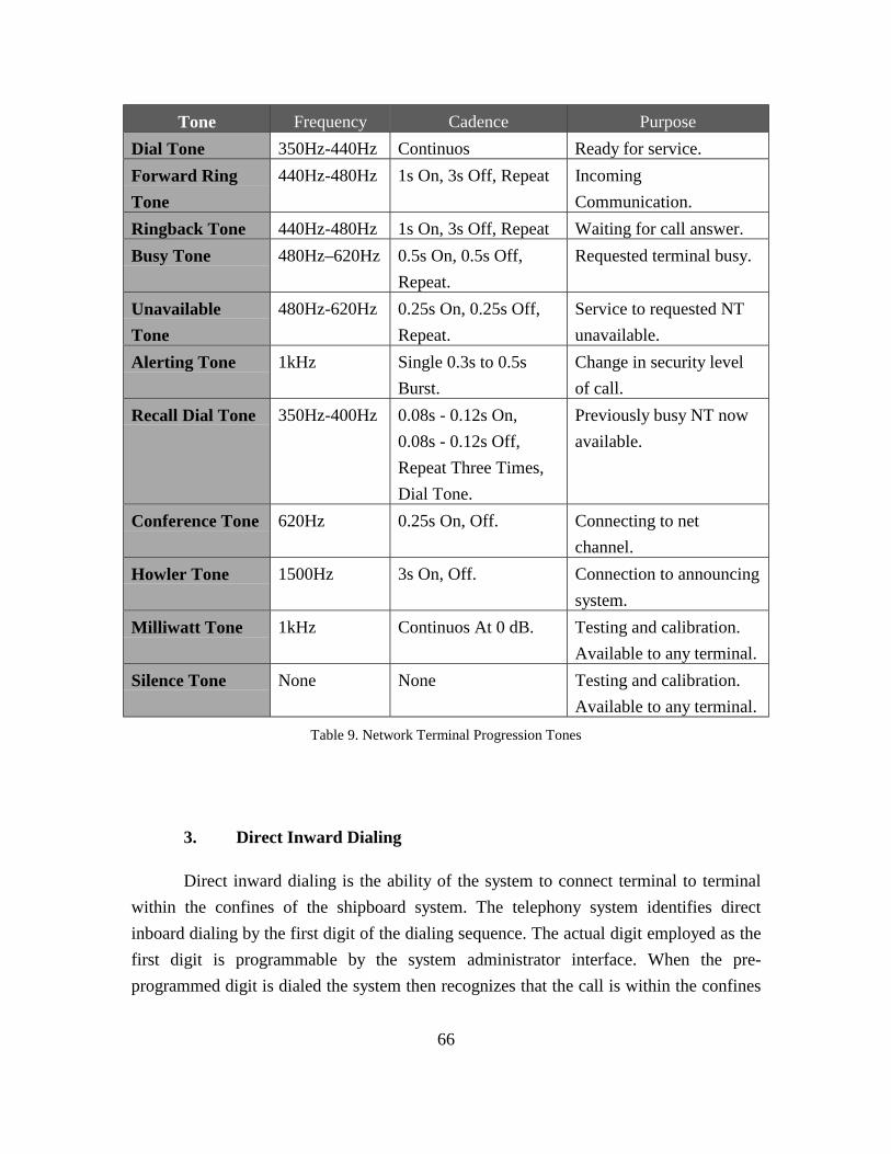
66
Tone Frequency Cadence PurposeDial Tone 350Hz-440Hz Continuos Ready for service.Forward RingTone
440Hz-480Hz 1s On, 3s Off, Repeat IncomingCommunication.
Ringback Tone 440Hz-480Hz 1s On, 3s Off, Repeat Waiting for call answer.Busy Tone 480Hz–620Hz 0.5s On, 0.5s Off,
Repeat.Requested terminal busy.
UnavailableTone
480Hz-620Hz 0.25s On, 0.25s Off,Repeat.
Service to requested NTunavailable.
Alerting Tone 1kHz Single 0.3s to 0.5sBurst.
Change in security levelof call.
Recall Dial Tone 350Hz-400Hz 0.08s - 0.12s On,0.08s - 0.12s Off,Repeat Three Times,Dial Tone.
Previously busy NT nowavailable.
Conference Tone 620Hz 0.25s On, Off. Connecting to netchannel.
Howler Tone 1500Hz 3s On, Off. Connection to announcingsystem.
Milliwatt Tone 1kHz Continuos At 0 dB. Testing and calibration.Available to any terminal.
Silence Tone None None Testing and calibration.Available to any terminal.
3. Direct Inward Dialing
Direct inward dialing is the ability of the system to connect terminal to terminalwithin the confines of the shipboard system. The telephony system identifies directinboard dialing by the first digit of the dialing sequence. The actual digit employed as thefirst digit is programmable by the system administrator interface. When the pre-programmed digit is dialed the system then recognizes that the call is within the confines
Table 9. Network Terminal Progression Tones

67
of the system and requires an additional three digits to complete the identification of thedestination terminal. The digit selected as the inward preamble should comply with thestandard shipboard dial plan.
4. Direct Outward Dialing
Direct outward dialing is the ability of the system to obtain a connection to anexternal network services without operator intervention. Direct outward dialing supportsadministrative services, is an administrative function and not a required feature fortactical communications support. Dialing a pre-programmed digit accesses direct outwarddialing. When the pre-programmed digit is dialed the system checks to determine if anexternal line is available. If there are no lines available the system returns a short busysignal to the requesting terminal. If there is a line available the system reserves systemresources and sets up a channel to allow communication between the terminal and trunklines.
Direct outward dialing posses significant issues for the voice over LANdevelopment. When communication extends beyond the confines of the control LANenvironment it has to conform to communications industry established standards. Thisrequires the protocols and signaling to back fit requirements even though there arestandards that are better suited for today communications needs.
Additional hotel services are required to support direct outward dialing. Thesystem has to have the ability to allow the user to place credit card calls, collect calls, andspecial billing cards without the assistance of an operator. This is a particular challengewithin the LAN telephony system. Commands over the telephony system are given andreceived in digital format while commands given in a commercial PBX are in analogformat. To meet both requirements the LAN based system must have a point ofdemarcation where a command, such as a key press from a tactical terminal, is convertedinto the analog equivalent acceptable to the external PBX.
The system also needs to provide for call cost accounting capabilities. Whenever acall is placed between terminals within the switch or charges are accepted from callsexternal to the switch, the system has to have the ability to track and record the chargesincurred by terminals. These charges may be outward shoreline connects as well asinternal satellite that are ship to shore connections.

68
5. Automatic Route Selection
The software has to provide automatic route selection across the local areanetwork. The system needs to provide for adaptive routing procedures to compensate fornetwork traffic pattern changes, circuit availability, or partial system failures. There aretwo primary reasons for requiring the automatic routing of signals within the LANenvironment. The primary reason is circuit failure protection and the alternate reason isload balancing. Load balancing is not a significant concern within the Navy environment,because the total bandwidth allocation is significantly greater the utilization requirements.In the future Navy requirements and in the commercial environment load balancing is asignificant concern. Most existing LAN technologies support automatic re-routing ofsignals upon the failure of a circuit. Employing one of these topologies will greatlyreduce the development overhead required to convert tactical communication to thenetwork environment. Care needs to be taken in ensuring that the desired LAN can meetthe automatic circuit rerouting without the disruption of service on any establishedcircuits or the system monitoring by the telephony server.
6. Net (Conference) Calling
Net calling in tactical communications operates similar to conference calling inPBX operations. In tactical communications there are three types of net calling. In tacticaloperations the first two net calling schemes, the tactical command net and meet-me net,are identical in operation. The command net is an assigned station for the terminal oroperator to dial into, depending on the status or alarm condition of the ship. The met menet operates in identical fashion as the command net, but participation is ad-hoc andterminals or operators are not pre-assigned and enter the net voluntary. The third type ofnet calling function in the same fashion as tradition PBX operations where a user can beadded by other another user already on the net are then removed when their connection isterminated to the connected NT. The net ceases to exist when all calls are terminated.
Because of the ability of any tactical terminal to connect to any net, multiple nets,any terminal and multiple terminals, it is possible for one terminal to render the entiretactical telephone system inoperable. To prevent improper operation of a networkterminal, access or classmarks (privileges and restrictions) can be pre-assigned to anyterminal limiting the functionality of the specified terminal. For some integrated terminal

69
interfaces the user may just want to monitor what is going on but not actively talk on thecircuit. At other times the user may want to talk while several other users only listen.
Both the tactical and met-me nets are always operational, whether or not there areterminals currently dialed into it. Any tactical terminal, with the proper class marks, cancall into the net and establish a connection at any time. Any user may leave the netwithout disruption of service to any other terminals currently on the net. Conceptually,the net is a perpetual party line where terminals may enter or leave at will without loss ofsignal.
7. Sound Powered Nets
The primary user of the two primary shipboard nets is the sound poweredtelephone (Figure 17). The sound power phone is a specialized tactical terminal. Thesound powered net is a string of one to many sound powered phones that have the abilityto communicate across a common cable without external power. Terminals connected tothe LAN based tactical telephony server have the ability to call into the sound powerednet by dialing a number associated with the net. The number of network terminals fromthe tactical switch dial into the net of the sound power telephone is unlimited. The soundpowered net does not have the ability to dial out and is permanently assigned to a tacticalnet. In essence it is a one way connection where sound powered phones have the ability toinstantaneously connect to other sound powered phone on the net and where other phoneshave to dial in to connect.
In commercial voice communications a bridge circuit is used to accomplish thenet feature. In the tactical voice over LAN a similar feature needs to be utilized. There arespecified phone numbers to dial when attempting to connect to a specified net. Once aterminal has dialed into the net their incoming signal is summed with all other signalsattached to the designated number and sent out to all connected terminals.
Although the telephony server could function in this capacity, it is notrecommended that this approach be utilized. The desired approach would be to add netservers to the LAN that function as a specialized network terminal or conference bridge.This would permit expansion of the net bridges by the simple addition of servers to theLAN and would free the telephony servers of additional responsibility. Because of the

70
low demand utilization on the net server, it would be expected that more than one servercould be incorporated into any single unit.
SourceController
Talk
Monitor
InternalSpeaker
ExternalSpeaker
Codec TacticalInterface
Sound PowerInterface
ControllerInterface
MonitorTalk
Internal SpeakerExternal Speaker
Source
ChannelController
PTT
Controller
a. Abbreviated And Speed Calling
In the current tactical system speed dialing is referenced as abbreviatedaddressing or dialing. Speed dialing and abbreviated dialing appears functionally similarto the operator but its implementation is not functionally the same. Speed calling is theability to place a call to a tactical net with a limited button press. This limited sequence ofdialed digits invokes a full dialing sequence that is sent out to a call control processor.Abbreviated dialing consisted of ability to walk down a dialing tree and have the callcompleted based on the termination of the tree walk. The tree termination may be aslimited as a single digit or as much as four digits, which can access all internal networkterminals. Both functions are required in the tactical telephony system. Theimplementation of speed dialing will most likely occur within the tactical terminal whileabbreviated dialing will functionally take place in the telephony server.
Individual speed calling has the ability of the user to program the localterminal with a redefined set of phone numbers according to their needs and desires.
Figure 17. Integrated Terminal Equipment Block Diagram

71
Individual speed calling functionality is located within the local terminal and is notcontrolled by any external means. The operator predefines a number then stores thatnumber in allocation within the terminal’s memory. To recall the number the operatorselects the recall function and the desired memory location to be recalled.
8. 18-Digit International Number Routing
Because terminals are used for administrative purposes as well as tactical, aterminal with the proper class markings is able to access trunk lines outside the limits ofthe tactical communication system. Eighteen digit dialing is the ability of a terminal toaccess international numbering plans. This ability is an administrative function notassociated with tactical communications. This feature is not normally associated withunderway operations and in used primarily when the ship is located pier side and thesystem is interconnected to shore communication facilities.
The eighteen digit dialing plan is accessed by dialing a specified prefix, such asthe digit 9, which then connects the caller to a PBX external to the ship which hasinternational dialing capability. The caller is connected to an external PBX via commoninterface format and protocols. This not only requires the tactical voice system to haveexternal capabilities, but also requires it to maintain a common interface standards andprotocols. In the voice over LAN effort this will require a specialized that interfaces to theexternal PBX.
For the voice over LAN to be a practical solution the internal system formats andprotocols should match common industry standards so the extended format appears as anextension to the internal system. In the event a common protocol standard is notachievable within the tactical voice over LAN system, an interface should be provided tothe commercial PBX that converts internal signals and protocols to commerciallyacceptable formats.
9. Caller Identification
Caller identification is the ability of the called terminal to be able to identify acalling terminal’s phone number and terminal station personal identifier prior toanswering (going off-hook) the call. The system administrator has the ability to assign
72
caller identification according to a predetermined calling plan. Each telephony servermaintains a configuration containing the system’s entire caller identification database.The data is updated using the system administrator’s interface. When the database ismodified within one telephony server it is then updated in all remaining telephonyservers. When telephony server comes on line for the first time it is also updated with thecurrent caller identification database.
10. Call Waiting
Call waiting is the ability of the receiving terminal, that is already off-hook, toknow there are one or more callers attempting to establish a connection. The calledterminal will have the ability to perform caller identification of any incoming calls thatare waiting to be established and select the desired calling terminal and place the existingconnect on hold. Because of the non-blocking requirement, all tactical network terminalshave to be able to accept all incoming calls. Call waiting adds to the ability of non-tacticalphone to accept at least one additional call before blocking is implemented.
The system establishes call waiting the same way it sets up a normalcommunications channel. Because the terminal is already off-hook the receiving terminaldoes not send back an off-hook command to the sending terminal. The incoming callrings back as if the receiving terminal was on-hook. Rather than producing a normalforward ring the receiving terminal produces an audible indicator on the receivingterminal indicating there is a call attempting to connect. The audible indicator is repeatedat a given interval until the caller goes on-hook or the called terminal places the incomingcall on hold and picks up the incoming call. As with any call, either terminal has theability to place the other party on hold, or to any net they are currently connected.
11. Call Forwarding
Call forwarding automatically transfers any incoming calls from a receivingterminal to another pre-selected receiving terminal. The calling terminal cannot abort thetransfer other than to terminate the call. Implementation of this feature could take place inreceiving terminal, but this would in effect double the number of steps to establishcommunication. The desired location for implementation would be in the telephony

73
server. The requesting network terminal would dial a predetermined phone number wherethe server would identify the calling unit and the user could selected the desiredforwarding number. Cancellation of the service would be accomplished in a similarmanner. An operator would only be allowed to implement and cancel call forwardingfrom the calling terminal.
12. Call Hold
Call hold allows network terminal with the class of service to place a calling partyin an inactive communication status. The network terminal that activates call holddeactivates all speaker and microphone capabilities. Call hold is activated within thenetwork terminal and has no effect on the network circuitry. No interaction is requiredfrom the telephony server or another device external to the activating network terminal.All connections remain in effect and no external operations are required. While in aninactive status either party can perform any other function of the terminal.
13. Call Park
Call park is similar in features to call transfer in that the answering party of anestablished call can park the calling terminal at a third party. The third party terminal thenhas the option to retrieve the parked call with a predetermined dial code. If the third partydoes not retrieve the call within a specified time, the calling terminal then rings theterminal that placed them on call park. If the third party does not retrieve the call within aspecified period of time the parked call rings back to answering party.
The implementation of call park requires the services of the telephony server andthe parking terminal for successful completion. The services of call park should bepreprogrammed into the terminal. The operator selects the caller to be placed on call park,then the call park feature is selected, the destination of the call park is selected and finallythe call is transferred. The forward ring, time out and ring back to the transferring partyare automatic and controlled within the transferring terminal. The telephony server doesnot require any knowledge of the implemented actions until the call is completed at theforward ring. At this time the telephony server establishes a connection between thetransferred and forward called terminal and disestablishes the original channel.

74
14. Call Transfer
Call transfer is the ability of a network terminal to transfer any call, in its entirety,to a third terminal. The telephony server uses the class of service and class marks of theterminal being transferred in determining the caller’s rights and privileges in establishingthe new connection. Call transfer is setup by the telephony server with the terminalinitiating the transfer acting as an agent for the transferring terminal. Once the call iscompleted to the third party across the network, the telephony server disconnects andtears down the circuit between the original parties.
15. Call Groups
Call groups is the ability of the network terminal to perform net conferencing.There are three types of net conferencing located within the tactical environment. Thefirst two types of call groups function exactly the same operationally; it is how they areemployed that differs. The first two types, the tactical net and meet me net, are conferencecall bridges that are always active and any terminals with the system that has adequateclass of service and has the class marks can access the call groups at any time. Thetactical net is used strictly for tactical purposes and shipboard management determines itsuse. The meet-me-net is used for conference calling that is not tactical in nature. The meetme net, like the tactical net, is always in existence and can have zero to many networkterminals connected. The third type of conference calling is established only when a thirdnetwork terminal is added to an existing call. This conference call is only in existence forthe duration of the call. The conference is terminated as soon as the last network terminalterminates its connection with the last network terminal within the net.
16. Camp-On
Camp on is the ability of a calling terminal that encounters a busy terminal to benotified when the called terminal is on-hook and the circuit is cleared and ready to receivean incoming call. The calling terminal can initiate camp-on when it encounters a busysignal by informing the telephony server that it desires to be notified when the calledterminal is available to receive calls. Once the desired circuit is clear the telephony server

75
rings back the caller. When the caller goes off hook the operator has the option toestablish a connection to the requested terminal or cancel the camp-on feature by goingon-hook.
Camp-on is implemented in the telephony sever and is based on the classmarks ofthe network terminal. A tactical network terminal with non-blocking class of servicecannot have camp-on based on classmarks. When camp-on is activated the networkterminal notifies the telephone server of the request to be notified when the circuit of thenetwork terminal becomes available.
17. Messaging
Messaging is the ability to communicate between terminals using an alphanumericbased store and forward procedure. The calling user enters a message using the terminal’sdata entry device and addresses the message to the desired receiving terminal. Themessage is routed through the telephony server as a designated source and then forwardedto the receiving terminal. The receiving caller can then review the message at theirdiscretion. Messaging does not require the system to establish a dedicated circuit and isprovided using the best effort of the system.
18. Voice Mail
Voice mail is the ability of the caller to leave voice messages, which the calledterminal can retrieve at a later time and date. Voice mail is activated when the callterminal is busy or forward rings a predetermined number of times and the called terminaldoes not go off-hook. Voice mail is pre-selected and monitored in the telephony server.When the telephony server determines the calling terminal has reached the criteria, theincoming call is rerouted to a predetermined smart recording device. The telephony servernotifies the smart recording device of the called terminals identification and themessaging device prepares call handling procedures unique to the called and callerterminals.
If the caller leaves a message the smart recording device notifies the calledterminal that there is a message in the terminal’s message box. The called person can then

76
retrieve the message from any terminal using the called terminal’s line number and apassword.
19. Push To Talk (PPT)
Push to talk (PPT) is a feature not normally found in commercial telephonesystems, but is essential in the tactical communications environment. The PTT featuresupports various radio nets, internal nets, intercom, interphone, and radiocommunications. The PTT feature is employed in simplex communication and where anybackground noise, from multiple network terminals, interferes with the ability of thelistener to clearly hear the communications. The talker (sender) of the communicationsactivates PTT by depressing a button located on the transmitting network terminal. Forradio communications, the system manages the audio within the system by the internalspeaker carrying speech on a plain circuit. PTT signaling, is not only required at thetransmitting NT but has to be passed through to the entire circuit to the receiving networkterminal.
The telephone server plays an active role in push to talk by determining if anetwork terminal has the push to talk class of service and to determine if the properclassmarks are in place. Push to talk is activated and de-activated in the networkterminal’s transmitting channel and does not interfere with the receiving channel, in bi-directional communications.
20. Special Connection Terminals
Special terminal connections are those connections that require an interfaceunique to a terminal type. The circuit may be a one to one connection, one to manyconnections or a device with multiple line interfaces where the incoming caller is routedto the next available circuit. For the operator to communicate on the circuit they mustactivate the push-to-talk feature. The primary capability of special connection terminals isthe ability of the receiving connection to complete the call without operator intervention.If the circuit is available, the receiving connection automatically forwards the off-hookcommand to the telephony server.

77
21. Shipboard Alarms
Network terminals with the proper class of service and with the proper appliedclassmark will be able to sound shipboard alarms, such as general quarters, by activatinga key feature or entering a predetermined dial key code. Alarms are activated via a specialconnection to the shipboard announcing system. The alarm sounds based on the activationof the circuit and ceases when the communication is terminated. The alarm willmomentarily pause when the PTT is activated, allowing simplex communications tospecial connection, and resume when the PTT is deactivated.
22. Class Of Service
Each terminal type connected to the tactical LAN based communications systemhas certain capabilities and limitations. The class of service for each terminal typeidentifies these capabilities and limitations. When a terminal attempts a connection to aterminal that is of a different class of service the system has to designate acommunications protocol prior to opening a channel for communications. It is theresponsibility of the telephony server to negotiate between the network terminals until amutually acceptable protocol is found. Most likely it will be the responsibility of thehigher class of service network terminal to convert to the protocol of the lower class ofservice device. Not all communications are possible from all network terminals. Fortactical communications the tactical terminals will have the highest class of serviceallowed by the system. Administrative terminals and special connections will have classof service limitations.
A primary function of the class of service is system security. Each networkresource has the ability to uniquely identify itself, its location on the network, and itsclass of service to the telephony server. The telephony server compares the unit’sidentification and the class of service sent to it against a database, preprogrammed by thesystem administrator, prior to allowing the NT to communicate across the network. Thisverification and validation process allows only authorized network terminals to access theassigned network channels and utilize system resources. Any attempt to circumvent theprocess and access system resources, including network terminals, without following theproper protocols would alarm the system administrator that improper activities weretaking place.

78
23. Classmarks
Each type of terminal located within the confines of the telephony system hascertain rights and privileges within the confines of the telephony system. Every networkterminal on the tactical telephony system contains classmarks. Classmarks provides ameans for the system administrator to assign rights and privileges for the operation of anygiven network device that further limit the class of service. A network terminal may havethe ability to perform given telephony functions, but may not have the rights assigned to itto use those functions. There are certain privileges, such as overriding an existingconnections and designated phone numbers, that have limited access rights. The class ofservice is assigned by the system administrator through the system administrator interfaceand is maintained within the telephony server database.
24. Classified Communications
The system has to allow a network terminal with the proper class of service andclassmarks to conduct unclassified and classified comminations concurrently. Classifiedcommunications is the ability to interchange information that has been classified by theUnited States government to be sensitive enough in nature that if it were to be acquiredby uncleared sources could place the warfighter in jeopardy. The ability to pass classifiedinformation by electronic means has to be approved by a government agency with theauthorization to make such a determination. At no time can an operator pass classifiedinformation by electronic means until the authorizing authority has approved the systemin its entirety.
25. Sensitive Communications
The system has to allow a network terminal with the proper class of service andclassmarks to conduct sensitive and non-sensitive communications concurrently.Sensitive information usually reveals knowledge that is not classified in nature, butshould not be provided to users of the system who are not authorized to know suchinformation. The ability to pass sensitive information by electronic means does not have
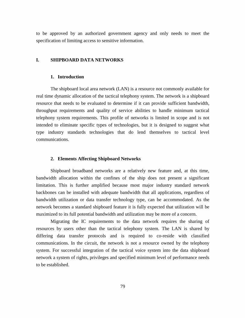
79
to be approved by an authorized government agency and only needs to meet thespecification of limiting access to sensitive information.
I. SHIPBOARD DATA NETWORKS
1. Introduction
The shipboard local area network (LAN) is a resource not commonly available forreal time dynamic allocation of the tactical telephony system. The network is a shipboardresource that needs to be evaluated to determine if it can provide sufficient bandwidth,throughput requirements and quality of service abilities to handle minimum tacticaltelephony system requirements. This profile of networks is limited in scope and is notintended to eliminate specific types of technologies, but it is designed to suggest whattype industry standards technologies that do lend themselves to tactical levelcommunications.
2. Elements Affecting Shipboard Networks
Shipboard broadband networks are a relatively new feature and, at this time,bandwidth allocation within the confines of the ship does not present a significantlimitation. This is further amplified because most major industry standard networkbackbones can be installed with adequate bandwidth that all applications, regardless ofbandwidth utilization or data transfer technology type, can be accommodated. As thenetwork becomes a standard shipboard feature it is fully expected that utilization will bemaximized to its full potential bandwidth and utilization may be more of a concern.
Migrating the IC requirements to the data network requires the sharing ofresources by users other than the tactical telephony system. The LAN is shared bydiffering data transfer protocols and is required to co-reside with classifiedcommunications. In the circuit, the network is not a resource owned by the telephonysystem. For successful integration of the tactical voice system into the data shipboardnetwork a system of rights, privileges and specified minimum level of performance needsto be established.

80
Bandwidth on demand is a technology of emerging network backbones. Althoughbandwidth on demand is a beneficial technology where traffic is bursty in nature, voicecommunication circuits must be designed to handle minimum sustainable levels ofbandwidth utilization. During “busy hour” the network must be able to handle all criticalcircuits of both voice and data without delays or loss of QoS.
In data networks, a best effort requirement is adequate to meet the minimumrequirements By introducing buffering and small delays in communications, totalutilization of a channel can exceed the maximum limits for short periods of time; thebandwidth can exceed peak capability and still function acceptably. In voicecommunications, if the limit of bandwidth utilization is exceeded there can be asignificant loss in the quality of service. If the loss is severe, then communicationsbecomes unintelligible. To prevent QoS loss the total utilization of the networkbandwidth must never exceed the ability of the voice communications system to meet theminimum bandwidth requirement of any single channel.
Bandwidth on demand becomes an effective technology if the system is notcapable of handling the maximum utilization of both tactical and administrativecommunication requirements. This does not pose a significant problem when consideringthat most current backbone technologies being installed aboard ships have OC-12bandwidth rates with sustainable utilization at rates of ninety percent or better. Thisbecomes critical, however, with LAN technologies with limited bandwidth in the outlyingareas.
Bandwidth on demand becomes practical if there is the ability to prioritizecommunications and allocate or de-allocate bandwidth accordingly. This requires thedevelopment of a LAN wide resource allocation system. This over arching system wouldhave to contain information of all critical systems and their priority within thecommunication environment. As the utilization of the bandwidth reached the maximumpotential, the system would reallocate bandwidth according to a predetermined senioritystrategy. Systems unknown to the administrator would be allowed to utilize bandwidth onan as available bases, but would be the first to be eliminated as resources became critical.

81
3. Shipboard Local Area Networks
Because the shipboard network is not a resource owned or maintained by thetactical voice system, horizontal integration of two competing technologies needs tooccur. No LAN based technology should be eliminated strictly based on topography orprotocol type. Any network that can meet minimum requirements should be considered.The development should have the ability to eventually utilize any suitable type of networkprotocol or topography.
Some technologies better lend themselves to this type of development. For thepreliminary prototype a best suited technology needs to be chosen. The selection of thedesired system should include shipboard availability, overall costs, and ability to supportemerging technologies as well as the capacity to accomplish the primary objective. Tobetter make this selection a basic understanding is required of those technologies thatbetter lend themselves to this type of development and are those that are the mostprobable choices.
a. Carrier Sense Multiple Access / Collision Detection (CSMA/CD)
Ethernet is the primary local area network used within industry and withinthe Navy. The specifications and rights to build Ethernet technology are publiclyavailable creating a large market of competitively priced equipment. The Institute ofElectrical and Electronics Engineers (IEEE) published the original standard under the title“Carrier Sense Multiple Access with Collision Detection (CSMA/CD)”and is adopted bythe International Organization for Standards (ISO) making it a worldwide networkingstandard.
BandwidthOverhead
Per PacketMinimum
Packet SizeMaximumPacket Size
10M Bits 18 Bytes 64 Bytes 1518 BytesTable 10. Ethernet Frame

82
The most widely used version of Ethernet is ten megabits per second(Table 10). It is also available at bandwidths of one hundred and one thousand megabitsper second. All stations are connected to a shared signaling system. Each station operatesindependently of all other stations and there is no central controller. Signals aretransmitted serially over the shared signal channel to every attached station. To send dataa station must listen to the channel and when the channel is idle the station transmits datain the form of a frame or packet. Each station with data to transmit must contend equallyfor the next transmission opportunity.
The logical topology of the Ethernet provides a single channel or bus thatcarries the signal to all stations. Multiple segments can be linked together to form a largerLAN using a repeater. Multiple segments grow as a non-root branching tree and eachmedia segment is an individual branch of the complete signal segment. The mediasegments may be connected in a physical star pattern, with multiple segments attached tothe repeater and the logical topology is still that of a single channel that carries signals toall stations. Segments can never be connected in a loop. The total set of segments mustmeet the round trip timing specifications as if it was a single LAN.
TransferRate
Packets(Minimum Packet Size)
Packets(Maximum Packet Size)
Voice 64K Bytes / Second1391.3 Packets / Second
(46 Byte Payload)42.12 Packets / Second
(1500 Byte Payload)
If more than one station attempts to transmit on the channel at any give time, thesignals are said to have collided. The stations are notified of this event and rescheduletheir transmission at a randomly chosen microsecond interval. This keeps the stationsfrom again attempting to transmit at the same time. In the unlikely event the collisions fora given packet transmission exceeds 16 consecutive collisions the interface will discardthe packet.
Hubs may also be used to extend the operational capabilities of each LANsegment. Connecting the Ethernet LAN together with hubs allows each segment of theLAN to operate as if it was a separate and distinct LAN where the timing requirementsare only applicable to the individual segment and not to the LAN as a whole.
Table 11. Combining Simplex Voice on 10 Mbit Ethernet

83
Voice TransferRate - Simplex
EthernetBandwidth
Bandwidth Utilization(Minimum Packet Size)
Bandwidth Utilization(Maximum Packet Size)
64K Byte/ s 10M Bit / S 7.12% 5.11%
Ethernet LANs operates as a best effort data delivery system (Table 11) whileaffording each user equal opportunity to gain access to the network. Ethernet technologydoes not have the ability to prioritize the users, deny services to unknown users or tousers of low priority, guaranteeing a minimum level of performance. In addition, thetypical maximum utilization of this type of technology is usually no greater than fortypercent of the total bandwidth (Table 12). For these reasons it is not recommended thatCSMA/CD be developed for the tactical aspects of the communications system.
b. Token Ring
Token ring is protocol architecture developed by International BusinessMachine (IBM) in the 1970s. It is a star wired ring topology having token passing as itsnetwork access method using a baseband transmission technique operating at 4 megabitsper second (Table 13). It is known as a deterministic method of access since a station canonly transmit data when the token is available to it. Once a station releases the token thenext station in the channel grabs it. No collisions can occur because only the station withthe token can transmit. Each station grabs the token when it is passed whether they havedata to transmit or not.
Token Header Payload Frame Size Efficiency3 Bytes 11 Bytes 0-4500 Bytes 14-4,514 Bytes 0-99.6%
Token ring transmission is a relatively efficient method of transmittingdata when compared to the bus topology of Ethernet. Precise timing of how long a frame
Table 12. Simplex Voice Channel over Ethernet Efficiency
Table 13. Token Ring Utilization

84
takes to travel the ring can be determined by the number of stations in the circuit, thepropagation delay between the stations (Table 14), the amount of data to be transmittedand the number of hops the receiving station is from the transmitting station.
PropagationAnalog Voice Data
PayloadOverhead Network Terminal Channels
4 Mbit/sec 64 Kbit/sec 112 bits/frame 60 Duplex
Token ring is not a common network found within the military orshipboard environment (Table 15). It is significantly more costly to purchase andmaintenance personnel have to have a higher degree of expertise to properly operate thesystem. Token ring is more prone to total system failure occurring from minor stationfaults. If there is a minor problem self-recovery can take up to several seconds. For majormalfunctions the ability of the system to have build in hot swappable back up is alsoharder to implement.
PropagationISDN Voice Data
PayloadOverhead Network Terminal Channels
4 Mbit/sec 144 Kbit/sec 112 bits/frame 27 Duplex
J. SHIPBOARD DATA BACKBONES
1. Asynchronous Transfer Mode (ATM)
Asynchronous Transfer Mode (Table 16) is the emerging technology of choice forshipboard network infrastructures. Similar to other data transfer technologies, ATM is avariable bit rate (VBR) service offering best effort to data transmissions. ATM offersseveral features conducive to voice communications not found in other data transfertechnologies. ATM also has the ability to setup virtual constant bit rate (CBR) circuits
Table 14. Analog Voice Over Token Ring
Table 15. ISDN Channel Over Token Ring
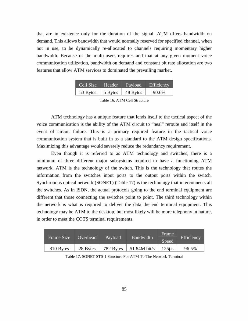
85
that are in existence only for the duration of the signal. ATM offers bandwidth ondemand. This allows bandwidth that would normally reserved for specified channel, whennot in use, to be dynamically re-allocated to channels requiring momentary higherbandwidth. Because of the multi-users requires and that at any given moment voicecommunication utilization, bandwidth on demand and constant bit rate allocation are twofeatures that allow ATM services to dominated the prevailing market.
Cell Size Header Payload Efficiency53 Bytes 5 Bytes 48 Bytes 90.6%
ATM technology has a unique feature that lends itself to the tactical aspect of thevoice communication is the ability of the ATM circuit to “heal” reroute and itself in theevent of circuit failure. This is a primary required feature in the tactical voicecommunication system that is built in as a standard to the ATM design specifications.Maximizing this advantage would severely reduce the redundancy requirement.
Even though it is referred to as ATM technology and switches, there is aminimum of three different major subsystems required to have a functioning ATMnetwork. ATM is the technology of the switch. This is the technology that routes theinformation from the switches input ports to the output ports within the switch.Synchronous optical network (SONET) (Table 17) is the technology that interconnects allthe switches. As in ISDN, the actual protocols going to the end terminal equipment aredifferent that those connecting the switches point to point. The third technology withinthe network is what is required to deliver the data the end terminal equipment. Thistechnology may be ATM to the desktop, but most likely will be more telephony in nature,in order to meet the COTS terminal requirements.
Frame Size Overhead Payload BandwidthFrameSpeed
Efficiency
810 Bytes 28 Bytes 782 Bytes 51.84M bit/s 125µs 96.5%
Table 16. ATM Cell Structure
Table 17. SONET STS-1 Structure For ATM To The Network Terminal

86
ATM has several inherent benefits and that help ensure quality of service (QoS)and make the service a prime candidate for network services on the tactical voicecommunications environment. The service has dynamic bandwidth utilization viamultimedia services. The service has the ability to dynamically prioritize utilization ofclasses of signals within each channel. ATM can dedicate bandwidth for constant bit rate(CBR) service. The fourth feature that makes ATM a popular choice for tacticalcommunications is the automatic rerouting of signals in the event of equipment failure orcircuit loss. By incorporating these inherent features of ATM into the implementation ofthe system the overall system reliability can be increased while reducing the cost and timeof the development.
Originally ATM proponents claimed it to be the end-all network solution. Thereare significant drawbacks employing ATM technologies in telephony developments. Thetechnology is not mature enough or the standards accepted industry wide, so theequipment from different manufactures has standardized on slightly differing interfaces.This makes the technology a single vendor solution and increases the probability ofincompatibly with emerging enhancements. Because ATM communications conventionsis many to many it can be difficult to scale the network. ATM is significantly morecomplicated to design, install and maintain than gigabit Ethernet or even FDDI. ATM iscostly and complex. (Gigabit Ethernet is a less costly and simpler alternative.) This makesthe technology complex and more difficult to maintain, requiring a much higher degree oftechnical sophistication.
2. Fiber Distribution Data Interface (FDDI)
FDDI is a technology (Table 18) that has operating features similar to token ring.The network has two one hundred megabit per second counter rotating rings. Only onering, the anti-clockwise ring, is active unless a fault occurs. A token is passed from onenode to the next and only the possessor of the node can communicate on the ring at anyone time. The times for servicing each of outlying nodes can be precisely predicted thusensuring a minimum service requirement. If the primary ring fails the secondary ringautomatically takes over communications. All nodes read the token to determine if theyare the recipients. If node is the recipient, it extracts the data. If a frame cycles back tosender, the originating station strips the frame and releases the token.

87
The primary advantage of FDDI technology is that it is proven technology.The cost of implementation is relatively low and the solution can cross multi-vendors.The token ring holding timer determines how many frames can be transmitted before ithas to move on to the next station resulting in a more precise knowledge of the time itwill require to transmit any data. The primary disadvantages of FDDI is its inability toself heal if the primary and secondary ring is broken. There is not an ability for thenetwork to self-monitor and control the problems within the structure.
Token Header Payload Frame Size Efficiency11 Bytes 17 Bytes 0-4478 Bytes 28-4,506 Bytes 0-99.3%
Table 18. FDDI Cell Structure

88
THIS PAGE INTENTALLY LEFT BLANK

89
V. COST OF OWNERSHIP
A. INTRODUCTION
During the early development of communications the military was a driving forcebehind the development of certain types of technology. These technologies weredeveloped at the expense of the government then converted to civilian use. Subsequently,commercial development has vastly surpassed the military in many arenas. Commercialof the shelf (COTS) equipment is being deployed with better features and manufacturedwith a higher degree of reliability than can be afforded by the military within the samedevelopment window.
It is more economical to deploy commercial systems than it is to develop in-housesystems unique to the Navy. The fundamental obstacle is that COTS systems do not meetthe total needs of the military tactical communication environment. The primary cause isthe limited market presented within the Navy. Research and development costs can beexceptionally high to meet unique needs. The vendor has to be able to market enough ofthese systems to cover their development costs. With the limited market presents of theNavy, there is little opportunity for the developer to recover these costs.
Because developing systems, such as the tactical voice communication system, areexpensive the objective of the development should be to maximize the utilization ofCOTS equipment when ever possible and only develop new systems and sub-systemswhen the functional needs of the shipboard requirements do not already exist within thecommercial environment. The resulting hybrid system would still be unique to the Navy,but by following accepted commercial standards with in-house developed sub-components there is a higher probability that commercial manufactures will provide theseservices as the demand for niche market increases. Using this methodology for the projectwill have the least impact on the Navy’s development dollar.
B. SYSTEM RELIABILITY
System reliability is not only the ability to properly function for extended periodsof time without failure, but also to be able to properly function in an adverse or hostile

90
environment. In the event of system failure, the failsafe procedures also have to providefor an orderly sequence of events in the instance of component, sub-system or entiresystem failure. This ability is the primary responsibility of the software that performsdiagnostics within the total system and executes hot cut over procedures with nodisruption in service. System reliability, as it relates to software engineering, not onlyconcerns itself with the ability of the firmware to function correctly over time and in amyriad of different possible situations, but needs to provide system redundancy andbackup in such a manner that no single point of failure causes a disruption in service.
C. SOFTWARE SYSTEM MANAGEMENT
In the shipboard tactical system there are several principal areas of systemmanagement concern. The first area is routine house keeping services. This is the abilityfor the shipboard operator to tailor the system to the specific, day to day, needs of eachindividual ship. The second area of software system management is the ability to maintainconfiguration control over an entire ship class. Configuration control is a softwarefunction usually maintained at a depot level maintenance where over arching ship to shipconfiguration management can be maintained. The third area of software management isthe ability to sustain life cycle maintenance control of any application or firmwaresoftware. Another area of primary concern, not normally associated with self-containedsystems, is the ability to maintain configuration control over non-native systems used, butnot owned, by tactical voice communications. All users of shared systems have certainrights to utilize features systems within the shared systems. Any system that is modifiedhas to be identified for use by all systems that utilize its resources.
It should be expected that the annual costs for software system managementwould start at approximately twenty percent of the total system development costs. As thesoftware becomes more stable, annual system management cost will reduce toapproximately ten percent of the total development costs. There will come a point ofdiminishing returns, when the cost to support software maintenance will far exceed theamount of productivity. Historically, it requires a minimum of one million dollarsannually to maintain a minimum level of effort support for this type of development.

91
D. SYSTEM MAINTANCE
The system has to be developed in such a way that it includes the ability of thesystem to self-monitor, self-diagnose, hot cut over, and report all system failures to thelevel require correcting the problem. Self-diagnostics has to have the ability to detect andreport in excess on ninety-eight percent of the problems of all software and hardwarecomponents. Because of the modular design of the system, there still in a smallpercentage of the problems that the system will not be able to report. Most of theserepairs will be outside the scope of the shipboard technician and will require depot levelrepairs.
The system has to be designed in such a way that no single failure of a componentor printed circuit board will cause the system to lose any functional capacity. Part of thesystem design requirements is to have at least one hot cut over capability per criticalsystem per switch. This means that two failures of the same component or board type onthe total system would not show any dedication in performance.
Because the system’s built in redundancy there is inherent spare parts built intothe system. The probability of three failures of the same nature within a limited windowof performance is extremely remote. In the event of three or more failures of a givencapability, and because of the conservative nature of shipboard tactical systems, the shipwould be required to carry replacements that can be hot inserted and become fullyfunctional without administrator intervention.
E. COST
The Navy approves for development only those systems that provide a significantincrease in capability or reduction in overall costs. Interior voice communicationsdevelopments are done with short term financial objectives and expending minimaldevelopment costs. Significant cost savings in the short term have to be demonstratedprior to approval of development. True cost savings may not be realized because of theinability to accurately predict actual development costs over the lifetime of the system.The problem is further compounded when development agencies low ball developmentcosts or inflate estimated savings to gain favorable reviews in the approval process. Thesefactors need to be taken into account when considering the system’s overall lifecyclecosts.

92
After market procurements can unexpectedly drive up a system’s over all costs.The interior voice system combats this serious cost increase by purchasing a significantamount of spare parts during the initial system procurement cycle. This type ofprocurement assumes that the system will be in service in its initial state for a specifiedperiod of time. If the system requires upgrading or maturity of the market surpasses thetechnology of the current development then the system can go into obsolescenceprematurely. The inclusion of two different types of technologies with associatedspecialized developments also increases the risk of untimely obsolescence.
The ability to combine legacy network terminals with newer LAN technologiesgives greater flexibility in configuring the system to meet current needs while providing aclear migration path for the future. This incremental migration capability is provided withreduced additional up front cost while supporting the system throughout the system’s lifecycle. The additional development cost are incurred if there are no existing COTSsystems that can meet the minimum requirements or the existing system does not meetthe additional burden placed on it by the combined services. There can be significantamount of risk, but this is usually occurs in the front end of the development and the riskis gradually eliminated as the system evolves.
When ever possible, the government should not be in the business of developinginterior voice communication systems or subsystems. The current state-of-the-art isalready far beyond what can be developed with the government’s limited funding, timeand resources. By utilizing COTS components the cost of development is placed on themanufacturer. Although the manufacture’s development costs are amortized into the salesprice of the unit, with limited deployed systems within the Navy, the increased unit priceis still substantially less than the total development costs if the Navy were to attempt todevelop the same system.
Support personnel is another significant cost consideration in the design elementsof a shipboard system. Shipboard labor is limited to begin with, and over the lifecycle of asystem a few hours of service requirement can accumulate into a significant amount. Bytraining shipboard personnel only in system administration functions and limiting thetechnical service requirements to the highest level possible, the Navy can extensivelyeliminate the need for highly trained service personnel.
There will still be a requirement to maintain highly qualified depot level staff oftrained personnel to perform service requirements beyond the scope of shipboardmaintenance. It is impracticable to maintain a highly qualified staff of shipboard

93
maintenance personnel to repair a system that will require service only an average ofevery couple of years. If an element within the system fails, the diagnostics capability hasto be able to have self-correction or isolation feature automatically cut in a backup. Thesystem should identify down to the lowest replaceable unit for which the shipboardtechnician should have spare parts and training to replace. In the event the system is notable to accurately diagnose the problem, the systems should have the ability to substituteor isolate services until the ship can make port in an area where depot level maintenanceis available.
The primary cost attention for new systems are the unknown factors of thedevelopment. The primary reason the military uses COTS components is because theycan provide a significant increase in ability while considerably reducing overalldevelopment costs. COTS systems do not always provide all the necessary elementsrequired for deployment on military platforms. This is especially appropriate whenconsidering the junction of voice and data. There are no known systems that can controlall the known requirements of regulating a data transfer system deploying voicetechnology or a voice system deploying data technology.
The problem is further compounded because of the lack of cross knowledgebetween video and data requirements of the developers. It is difficult to find developerswith detailed knowledge of both data and voice requirements. There are knowledgeablehigh level engineers available when developing a system in either technology and thereare plenty of third party resources for developing either type of systems, but there are fewresources that thoroughly incorporate both specifications. As both systems convert almostexclusively to COTS, the lack engineering resources available to the government fordevelopment increases the risk and cost of successful conclusion.
F. MODULAR DESIGN AND OPEN STANDARDS FOR INTEROPABILITY
Modular design is the ability of the system to compartmentalize functionality insuch a manner that as new functionality is required or new functionality becomesavailable the changes needed to upgrade can be implemented with minimal impact on anyadjoining functionality. Modular design is achieved by clearly specifying the purpose ofthe function and by defining the interface at the junction of the function. The actualprocess within the function does not have to be known and can be developed by

94
independent sources. Implementing a design of this nature creates significant front-enddesign costs, but provides the best value for the government’s overall cost of ownershipwithin life cycle maintenance.
The ability of current telephone systems to maintain open standards forinteroperability is minimal at best. The core of all phone systems being installed by theNavy, regardless of the manufacturer, is proprietary in nature. While this method ofsystem design decreases the overall development effort and increases the profits of themanufacturer, which is a necessary part of any product, it severely hampers the ability ofthe Navy to obtain the best value for its investment dollar.
Developing the system without using open standards at its primary interfacejunctions hampers the ability to incorporate new technologies. This encumbers the lifecycle to the points where it is more cost effect to discard the old system in its entirety andbegin anew. By compartmentalizing technologies and providing open standards forinteroperability, creating clearly defined points of demarcation where one technologyterminates and another begins, gives the system the ability to incorporate newtechnologies and defers system obsolescence.
Compartmentalizing system functionality decreases the ability to optimize thesystem performance and increases system design and testing standards requirements. Thisincrease in requirements also significantly increases overall development costs, which is aprincipal reason why modular design is not utilized. If modular design was applied to thedevelopment of the system, the lifecycle support effort would become significantly easier,overall long term support costs could be greatly reduced and life expectancy of the systemwould be greatly extended.
95
VI. CONCLUSIONS
A. CONCLUSIONS
The modernization of fleet communications will enhance the Navy’s ability tosupport military operations and how information will be exchanged. The rapid advance incommercial communication is the concept driving network centric warfare. Thetechnology is currently available within the commercial market, but is not yet matureenough to be purchased as a complete, totally encompassed, commercial system.
Rapid advances in technology make it imperative that upgrades be completedwithin a limited development window. The new system must also evolve to utilizeresources not owned, controlled or totally encompassed within the boundaries of the standalone development. This requires evolving from a tightly controlled centralized process todevices that are loosely coupled where once the information has left the network terminalinterface there is limited influence between nodes handling the information.
Attempts at replacing the tactical voice communications system have been abottom up approach. The developers have started at the lowest level of development withlimited regard for the overall objective or interactions of the system. Development needsto be a top down approach. The Navy should develop a comprehensive set of systemspecifications and a predetermined set of quality of service performance testing standards.Competitive bidding for the actual development of the system will allow the market placeto determine the best overall approach and technology for the solution.
The Navy’s shipboard tactical communications has extremely unique user andsystem requirements (Table 19). Just as the differential between software and hardware isbecoming less distinguishable, there is a blurring line between technical and politicalrequirements. Technical requirements, as outlined in this document, are only a partialfulfillment of the total requirement specifications. The implementation of the combinedtactical voice and data system has to meet several non-software requirements prior todevelopment before it can be considered a viable replacement for the existing systems.

96
Man power reduction.Space reduction.
Infrastructure reductionIncorporate legacy systems.
Maintain QoS at the network terminal.Retain Total Functionality Of Both
Systems
There have been several attempts by several Navy agencies to upgrade the tacticalvoice communications system utilizing commercial components and in-house engineeringsupport to cover the shortfalls. Each of these attempts has ended in failure and the lessonslearned have not been realized by the follow on attempts. These efforts did not have aclear understanding of the top level specifications or what criteria will be used indetermining the successful completion of the milestones and development.
Although some systems exist in the commercial arena that appear to have most ofthe qualities and features of the required specifications, a closer examination exposessignificant deficiencies. Some services are considering voice over internet protocol(VoIP) as a means to achieve tactical PBX and network convergence. VoIP does haveseveral appealing properties, but also has several inherent limitations that constrain itsappeal as a means for tactical communications.
By utilizing well-established standards based quality of service characteristics theNavy can develop a shipboard tactical voice communications system specification. Thisimplementation should incorporate PBX functionality across a distributive data network.By adding gateway components the network will connect the public switched telephonenetwork. The inter-connecting links should incorporate standard PSTN protocols forcommercial grade trunking and network terminals.
Communication advances, within and throughout the world, are revolutionizingthe industry. In the foreseeable future, massive amounts of information can beinstantaneously delivered to any point in the world. Critical information provided in theright place at the right time can reduce the resources required to accomplish the desiredobjective. The objective of the tactical communication system is to utilize and sharecommon resources among competing systems. However, the flow of information is only
Table 19. Pre-Development Stipulations

97
providing a limited scope of the requirement; this gets the information from the source tothe destination in the most efficient manner while meeting minimum deliveryrequirements. Future specifications will need to include the ability of the system tocompartmentalize the information and present it in a prioritized format.

98
THIS PAGE INTENTALLY LEFT BLANK

99
LIST OF REFERENCES
Gigabit Ethernet Alliance, “Gigabit Ethernet Accelerating the Standard for Speed”, WhitePaper, 1998.
Shok, Glen, “Here’s Packet Over SONET in a Nutshell”, URL:http://ww.wcmh.com/98/98apr/804b072a.html, 27 April 1998.
Boggs, David R., Mogel, Jeffrey C., Kent, Christopher A., “Measured Capacity of anEthernet: Myths and Reality”, Western Research Laboratory, Sept 1988.
“Ethernet Technologies”, URL:http://cisco.com/univercd/cc/td/doc/cisintwk/ito_doc/ethernet.htm, (Sept 1999).
“Maintenance Manual For Integrated Voice Communications System AN/STC-2(V)”,Commander, Naval Sea Systems Command, 1 April 1983.
“MarCom IVCS Switch”, User / Operator Manual, Revision A, L-3 Communications, 14January 2000.
IEEE 8802-3 Std – 1996, IEEE CSMA/CD Access Method.
Amit Shah, G. Ramakrishnan, Akrishan Ram (Contributor), “FDDI: A High SpeedNetwork”, Prentice Hall, 4 August 1993.
Sean Riley, Robert A. Bryer, “ “Switched, Fast, and Gigabit Ethernet”, MacmillianTechnical Publishing, January 1999.
Ming-Chwan Chow, “Understanding Sonet Sdh : Standards & Applications”, AndanPublishing, December 1995.
Robert Caputo, “Cisco Packetized Voice and Data Integration”, McGraw Hill Text,October 1999.
Regis J. Bates, Donald W. Gregory, “Voice and Data Communications Handbook:Signature Edition”, McGraw Hill, 3 December 1997.
“The CAPS Graphic Editor Manual”, URL:http://wwwcaps.cs.nps.navy.mil/Manuals/manuals.htm
James, Rumbaugh, Michael Blaha, William Premerlani, Frederick, William Lorensen,“Object-Oriented Modeling And Design”, Printice Hall, 1991.

100
Bruce Powel Douglass, “Real-Time UML: Developing Efficient Objects For EmbeddedSystems"” Addison-Wesley, May 1998.

101
INITIAL DISTRIBUTION LIST
1. Defense Technical Information Center8725 John J. Kingman Road, Ste 0944Fort Belvoir, VA 22060-6218
2. Dudley Knox LibraryNaval Postgraduate School411 Dyer RoadMonterey, California 93943-5101
3. Professor Luqi, Code CSNaval Postgraduate SchoolMonterey, CA 93943
4. Professor John Osmundson, Code CC/OSNaval Postgraduate SchoolMonterey, CA 93943
5. Glenn R. Urie10891 East Haven CourtSantee, CA 92071