Embed Size (px)
Citation preview
N
OF4
Real-Time Flight Simulation and the Head-MountedDisplay - An Inexpensive Approach
to Military Pilot Training
THESIS
Philip Anthony PlattCaptain, USAF
AFIT/TCS/ENG/90D-1i T ICLECTE
jAN081991DEPARTMENT OF THE AIR FORCE i E
AIR UNIVERSITY
AIR FORCE INSTITUTE OF TECHNOLOGY
Wright-Patterson Air Force Base, Ohio
91 1 3 066 Appro s
I' "'V Distributiou UUI100"
AFIT/GCS/ENG/90D-11
Real-Time Flight Simulation and the Head-MountedDisplay - An Inexpensive Approach
to Military Pilot Training
THESIS
Philip Anthony PlattCaptain, USAF
AFIT/GCS/ENG/90D-11
Approved for public release; distribution unlimited
AFIT/GCS/ENG/90D-11
Real-Time Flight Simulation and the Head-Mounted
Display - An Inexpensive Approach
to Military Pilot Training
THESIS
Presented to the Faculty of the School of Engineering
of the Air Force Institute of Technology
Air University
In Partial Fulfillment of the Accession For
Requirements for the Degree of 7 TIS GRA&IDTIC TAB
Master of Science (Computer Engineering) Unannounced. Tustif ication__----,-
BySDistributi on/
Philip Anthony Platt, B.S. iltributy ri/Availallityae
Captain, USAF
December, 1990 __.
Approved for public release; distribution unlimited -
Preface
Virtual flight simulators built with low-cost head-mounted display technology
may improve the military's future pilot training capability. Initially, these systems
may provide task-specific capabilities with the possibility of future systems that
provide combat training capability.
I would be totally remiss if I didn't acknowledge all those who assisted me
in the completion of my thesis. First of all, I'd like to thank my thesis advisor,
Maj Phil Amburn, for his words of wisdom and encouragement. Thanks to my
committee members, Maj Dave Umphress and Dr. Tom Hartrum. A special thanks
to my sponsors at the Air Force Human Resources Lab and Armstrong Aerospace
and Medical Research Lab.
I'd also like to thank my co-conspirators in graphics: Bill DeRouchey, Buck
Stuart, and Dave Dahn. Their wealth of knowledge, support, friendship, and sug-
gestions were invaluable to me. It was a tough 18 months, but our teamwork and
comraderie paved the way for successful completion of this project. Two other in-
dividuals deserve special credit for their assistance on this project. Thanks to Ed
Williams for his help in mastering the C programming language and to Dick Wager
for his help in getting the RS-232 cables and small supplies needed for the virtual
flight simulator.
Finally, I'd like to thank my wife, Gineen, and my children, Tina, Jennifer, and
Mary, for their support in this effort. I could not have finished this thesis without
their love and support.
Philip Anthony Platt
ii
Table of Contents
Page
Preface. .. .. .. .... ... ... ... ... ... ... ... ... ...... D
Table of Contents .. .. .. ... ... ... ... ... .... ... . .. ... i
List of Figures .. .. .. ... ... ... ... ... ... ... ... ... ... vii
List of Tables .. .. .. .. ... ... ... ... ... ... ... ... ..... viii
Abstract .. .. ... ... ... ... ... ... ... ... ... ... ..... ix
1. Introduction. .. .. ... ... ... ... ... ... ... ... .... 1
1.1 Background. .. .. .. ... ... ... ... ... ... ... 1
1.2 Thesis Statement. .. .. .. .. .... ... ... ... ... 4
1.3 Assumptions .. .. .. .. .. ... ... ... ... ... ... 5
1.4 Scope .. .. .. ... ... ... ... ... ... ... ..... 5
1.5 Approach. .. .. .. ... ... ... ... ... ... .... 6
1.6 SLmmary. .. .. .. ... ... ... ... ... ... .....
1.7 Thesis Overview .. .. .. ... ... ... ... ... ......
11. Literature Review .. .. .. ... ... ... ... .... ... ...... 10
2.1 Pilot Training - the need for simulators .. .. .. .. ...... 10
2.1.1 Budgetary Factors. .. .. .. .. .. .... ...... 10
2.1.2 Safety .. .. .. .. .. .. .... ... ... ...... 11
2.1.3 Readiness. .. .. .. .. .. ... ... ... ..... 11
2.1.4 Training Availability. .. .. .. .. .. ... ..... 11
2.2 Flight Simulators .. .. .. .. ... ... ... ... ..... 12
iii
Page
2.2.1 Simulator Types ........................ 12
2.2.2 Modeling Techniques ...................... 13
2.2.3 Visual Display Methods .................... 13
2.3 Virtual World Environments ..................... 14
2.4 Head-Mounted Displays ........................ 15
2.5 Computer Image Generation Systems ................ 16
2.6 Communications ...... ....................... 17
2.7 Summary ....... ........................... 18
III. Requirements Analysis ....... .......................... 19
3.1 Hardware ....... ........................... 19
3.1.1 CIG System ........................... 19
3.1.2 Communication Devices ................... 20
3.1.3 Head-Mounted Display ..................... 21
3.2 Software ................................... 22
3.2.1 Flight Modeling ........................ 22
3.2.2 Simulator Displays ....................... 23
3.2.3 Communications ........................ 24
3.2.4 Compatibility Issues ...................... 25
3.3 Man-Machine Interface .......................... 26
3.3.1 Physical Interface ....................... 26
3.3.2 Visual Interface ....... .................. 26
3.4 Summary ....... ........................... 27
IV. System Design and Implementation ........................ 28
4.1 Hardware Selection ............................ 28
4.1.1 Computer Image Generation System ........ ... 28
4.1.2 Input Control Devices ..................... 29
iv
Page
4.2 Software Selection. .. .. ... ... ... ... ... .... 29
4.2.1 Models Available .. .. .. .. .. .. .... ...... 29
4.2.2 Model Selected. .. .. .. .. .. ... ... ..... 31
4.2.3 Limitations .. .. .. .. .. ... ... ... ..... 32
4.3 Methodology. .. .. ... ... ... ... ... ... .... 32
4.4 Flight Controls .. .. .. ... ... ... ... ... ...... 32
4.4.1 Throttle Control .. .. .. .. .. ... ... ..... 32
4.4.2 Flight Stick Controls. .. .. .. .. .. ... ..... 34
4.4.3 Other Controls. .. .. .. .. .. ... ... ..... 36
4.5 Displays. .. .. .. ... ... ... ... ... ... ..... 36
4.5.1 Out-the-Window Displays. .. .. .. .. .. ..... 36
4.5.2 Cockpit Displays .. .. .. .. .. ... ... ...... 40
4.6 Head-Mounted Display .. .. .. .. ... ... ... ..... 45
4.6.1 Poihemus Tracker Description .. .. .. .. .. .... 45
4.6.2 Hardware Integration .. .. .. .. ... ... .... 46
4.6.3 Software Integration. .. .. .. .. .. .... .... 47
4.7 Compatibility Issues .. .. .. ... ... ... ... ..... 43
4.8 Summary .. .. .. ... ... ... ... ... ... ..... 49
V. Summary and Conclusions. .. ... ... ... ... ... ... .... 50
5.1 Summary .. .. .. ... ... ... ... ... ... ..... 50
5.2 Results and Analysis. .. .. .. ... ... ... ... .... 51
5.2.1 System Capabilities .. .. .. .. ... ... ...... 52
5.2.2 Frame Update Rate .. .. .. .. .. .... ...... 52
5.2.3 Display Systems .. .. .. .. .. ... .... .... 55
5.2.4 Human Factors. .. .. .. .. .. ... ... ..... 56
5.2.5 Network Communications. .. .. .. .. .. ..... 56
5.2.6 Problems Encountered .. .. .. .. .. ... ...... 57
V
Page
5.3 Conclusions .. .. .. .. ... ... .... ... ... .... 57
5.4 Recommendations for Future Research .. .. .. ... .... 58
5.5 Closing Comments. .. .. .. ... ... ... ... ..... 59
Appendix A. Microstick Description .. .. ... ... ... ... ..... 60
Appendix B. Cockpit Description .. .. .. ... ... ... ... ..... 62
B. 1 Modeling .. .. .. ... ... ... ... ... .... .... 62
B.2 Cockpit Description .. .. .. .. .. ... ... .... .... 63
Bibliography. .. .. ... ... ... ... ... ... ... ... ... ..... 66
Vita. .. .. .. ... ... ... ... ... ... ... ... ... ... ..... 69
vi
List of Figures
Figure Page
1. Joystick Data Structure .. .. .. .. ... .... .... .... ..... 34
2. Typical Out-the-window View of the VFS .. .. ... ... .... ... 39
3. Cockpit Instruments for the VFS. .. .. ... .... .... ... ... 41
4. VFS Virtual Interface Equipment .. .. .. ... .... .... ..... 47
5. Polhemus Data Structure. .. .. .... .... ... .... ...... 48
6. Virtual Flight Simulator .. .. .. ... .... .... .... ... ... 51
V11
List of Tables
Table Page
1. Microstick Output Data Structure ..... ................... 34
2. VFS Flight Control Selection Method ..... ................. 37
3. Display Update Rates ....... .......................... 53
4. Operating/Output Modes for the Microstick .................. 61
5. Baud Rates for the Microstick ............................ 61
6. Cockpit Branch Descriptions ...... ...................... 64
viii
AFIT/GCS/ENG/90D-11
Abstract
> The integration of the low-cost head-mounted display (HMD), an inexpen-
sive graphics workstation-based flight simulator, and a communications network was
investigated to determine if the prototype of an inexpensive multi-aircraft Virtual
Flight Simulator (VFS) could be built. Previous research efforts have coupled HMD
technology and flight simulation; however, the cost of these systems has been high.
This thesis effort emphasized the use of joystick devices to emulate pilot control,
the implementation of a fully enclosed virtual flight simulator, and the utilization
of low-cost NTSC-based television technology to produce a prototype. The virtual
flight simulator also contained a basic set of instruments to help the pilot control the
aircraft. The virtual world provided a full color 360 degree viewing capability which
allowed the pilot to look around his aircraft and world. Although the display update
rates of the final system were less than ideal, the results showed that the concept
of virtual flight simulators has potential for improving the Air Force's overall pilot
training capability.
ix
Real-Time Flight Simulation ana the Head-Mounted
Display - An Inexpensive Approach
to Military Pilot Training
I. Introduction
The purpose of this thesis effort was to investigate the integration of a low-cost
head-mounted display (HMD), a communications package, and a basic flight simula-
tor to provide the prototype for an inexpensive multi-aircraft part-task trainer. The
head-mounted display provided the platform for a full-color virtual world environ-
ment. By placing the HMD on his head, the pilot is immersed into a fully-enclosed
computer-generated world with a 360c viewing capability. The flight simulator also
contained a virtual cockpit with simulated aircraft instruments to increase the real-
ism of the virtual world and to improve the pilot's ability to fly the aircraft. The
pilot controls his aircraft by using joysticks that emulate the aircraft's throttle and
flight stick.
A focus of this thesis effort was to determine whether a low-cost National
Television Syscem Committee (NTSC) based head-mounted display could be used
as the viewing device for a real-time part-task flight trainer. Another focus was to
determine the size of the graphics engine required to provide this part-task trainer.
In particular, this effort focused on using an inexpensive high-performance graphics
workstation as host for the virtual flight simulator.
1.1 Background
At present, several Air Force organizations are involvec, in research of flight
simulators and head mounted displays. This research is important for many reasons.
1
First, simulators are safer to operate than aircraft. Use of the simulator removes the
risk of pilot or aircraft loss. Second, simulators operate at less than one tenth the
costs of an actual aircraft[13]. Third, flight simulators enable the pilot to train on
abnormal occurrences such as loss of an engine, or landing gear. Last, simulators
allow tasks to be repeated many times over a short period, reinforcing lessons learned.
Two Air Force agencies are sponsoring this effort: The Air Force Human Re-
sources Laboratol. (AFHRL), Flight Training Division; and the Armstrong Aero-
space Medical Research Laboratory (AAMRL), Human Factors Division. These
organizations are interested in different aspects of the flight simulation and head-
mounted display arena.
The AFHRL is interested in the flight simulator for its pilot training appli-
cations. One of AFHRL's technical planning objectives deals primarily with pilot
training. Hughes and Brown state "The general objective of this thrust is to identify
and demonstrate cost-effective training strategies and training equipment capabil-
ities for use in developing and maintaining the combat effectiveness of Air Force
aircrew members" [15:2].
One of the goals of the AFHRL is to design and develop the ideal combat mis-
sion trainer (CMT)[2]. To date, the AFHRL has been able to build dome simulators
using the advanced simulator for pilot training (ASPT) software. In search of the
ideal CMT, the AFHRL has studied multi-aircraft combat simulators. The labo-
ratory has provided research funding for multi-aircraft simulator training involving
both pilots and controllers. The primary focus of the simulation is on combat tactics
rather than every-day tasks [16:75]. Still another research effort of the AFHRL is
an advanced technology visual system capable of air-to-surface combat, air-to-air
combat in a one-on-one or two-on-two mode, airfield operations, and refueling[111.
AFHRL is now developing a prototype two-aircraft combat mission trainer[11].
Although the AFHRL has made vast strides towards their goal of an ideal
CMT, the costs involved are too high for squadron level distribution. The AFHRL
2
is now looking at the possibility of an inexpensive multi-task trainer. Coupling the
HMD and inexpensive workstation based computer image generators could provide a
solution to their dilemma. The minimum resolution of the HMD required for reason-
able fidelity is that of a standard 512-line television set[11]. "Full vision capability
is required because of the intensely critical aspect of vision in air-to-air combat" [11].
Enemy targets must be identified as soon as possible. Furthermore, the resolution
must give the pilot enough information about the environment so he (or she) can
make valid judgments regarding current aircraft status. The next generation HMD
now under development at the Air Force Institute of Technology (AFIT) may satisfy
this iequirement.
The AAMRL is looking at flight simulation and virtual world environments
from a different perspective than the AFHRL. The AAMRL is concerned with the
human factors involved in flight simulation; i.e. how the pilot interfaces with the sur-
rounding cockpit. The AAMRL is studying the development of a "super cockpit" [10].
In this super cockpit, the pilot would not only be able to see surrounding objects and
terrain but he can see the threat regions of various enemy defenses. The pilot could
maneuver the aircraft safely through these regions without detection (provided the
threat data are accurate). Because the entire cockpit is being graphically displayed,
the cockpit can be easily changed from one type aircraft to another. The software
would be configurable to allow the pilot to select the type of cockpit he prefers. The
super cockpit is composed of three major components:
" A head-mounted display to provide a full 3600 virtual world environment.
" Audio feedback for the pilot that would allow him to sense the direction of the
source of the audio feedback.
* A tactile feel to fool the pilot into believing he has depressed an instrument or
device. The pilot may not have depressed a physical button, but he must have
confirmation that a certain switch or button has been engaged.
3
The AAMRL is also interested in mission planning and command and control
applications using the HMD. In theory, a mission planner could evaluate several
"what-if" scenarios to determine the best possible plan. For example, an electronic
warfare aircraft (EF-111) would be placed in several different locations in the battle
area to determine its effect on enemy threat regions. The mission planner could then
plan his strike mission based upon the results of several scenarios.
The Air Force Institute of Technology has been actively involved in research
of the head-mounted display. Two generations of HMDs have been developed at
AFIT[10, 26]. The HMD has been used to provide mission replay of RED FLAG
exercise data[20]. Another application of the HMD at AFIT involved the preview
of parts of an air tasking order[35]. This application allowed the pilot to preview
the entire mission from start to finish. If any problems are encountered during
the preview, the pilot can determine why the situation occurred. Finally, the head
mounted display was used to create a 3-D virtual environment display system. The
previous work done at AFIT supports the concept of coupling the HMD and a flight
simulator to develop a prototype of a multi-ship mission trainer.
1.2 Thesis Statement
The integration of AFIT's head-mounted display system, an inexpensive graph-
ics workstation-based flight simulator, and a communications network can provide
an inexpensive multi-aircraft Virtual Flight Simulator (VFS).
The cost associated with current dome simulators is prohibitive. Several or-
ganizations have studied the feasibility of coupling head-mounted display systems
and flight simulators[ll, 13, 22, 36]. However, these past research efforts have dealt
primarily with high-cost computer image generation systems and expensive HMD
devices. The primary focus of this thesis effort was to study a low-cost alternative
to current flight simulators.
4
1.3 Assumptions
The following assumptions were made from the beginning of the thesis effort:
* A Silicon Graphics IRIS workstation would be used to host the VFS commu-
nications and simulation software. The workstation hardware would include
Ethernet connections, and a minimum of three RS-232 connections for I/O
devices.
" Two RS-232 type joysticks could satisfactorily emulate an aircraft's flight stick
and throttle. The realism of the joysticks was not as critical as the concept of
using a flight stick and throttle to control the aircraft.
" The screen update rate is more critical than the scene content. In any trade-
off situations, scene content will be reduced to maintain the minimum refresh
rates. The absolute minimum allowable update rate without degradation in
visual perception is 15 frames per second.
" Availability of a Polhemus 3SPACE Isotrak magnetic device or some equiva-
lent device to track head movement and to notify the simulator of any such
movements.
1.4 Scope
The range of possibilities for implementing the virtual flight simulator are too
numerous to list. Ideally, several workstation-based virtual flight simulators could
be connected across a network to provide a low-cost solution to both part-task and
combat training. Pilots could receive task-specific and combat simulation training
in a single room. In reality, the goal of this thesis was to study the feasibility of
connecting a low-cost head-mounted display and an inexpensive workstation-based
flight simulator.
The complete design and implementation of a flight simulator was outside the
scope of this research effort. The flight simulation software was modified from an
5
existing package to provide the necessary flight dynamics to fly the simulator. These
software routines provided rudimentary flight dynamics for a fighter type aircraft.
The virtual flight simulator was also limited to a two ship operation which is
the basic flying unit of the USAF[11]. The capability to connect a second ship to
the virtual flight simulator was provided through a cooperative effort with Capt.
David Dahn. The communication link satisfied the multi-aircraft requirement of the
virtual flight simulator. Capt Dahn's simulator was hosted on a PC based machine
using two Intel 1-860 processors for graphics.
A long-term goal of this thesis effort was to investigate the implementation
of the SIMNET protocol to determine if it could provide the necessary communica-
tions between the two aircraft. Emulating SIMNET protocols allows us to evaluate
the possibility of integrating this system with the current SIMNET system at Fort
Knox. Future research may determine the maximum number of aircraft that can be
simulated using the SIMNET protocol while maintaining the required update rates
for quality display.
1.5 Approach
A literature review was completed to determine the exact nature of the prob-
lem. This review covered research efforts in pilot training, simulation, virtual world
environments (to include head-mounted displays), computer image generation (CIG)
systems, and communication protocols. The literature review provided a raison
d'itre for the entire thesis effort.
Thc actual design and implementation of the VFS system had six areas of
interest:
1. Hardware: The computer image generation (CIG) system to host the VFS and
input devices to control the aircraft were selected.
6
2. Software: The flight dynamics software was selected from several available
packages. Silicon Graphics' flight/dog software was selected as the flight model
for the VFS. The reasons for this selection are discussed in Chapter 4.
3. Flight Controls: Joysticks were integrated into the VFS to provide a new
user interface. This integration process involved both hardware and software
actions. For example, null-modem cables were made to allow proper hand-
shaking between the CIG and the input devices. These input devices provided
a means of selecting and activating all necessary pilot controls for the VFS.
4. Out-the-Window Views: Out-the-window views were developed to help the
pilot fly the aircraft. To get a better idea of what type of information a
pilot would need in a flight simulator, the advice of Air Force pilot, 1st Lt
Mark Austin, was solicited[3]. Lt Austin provided valuable insight concerning
the minimum display information needed for a pilot to control his aircraft.
The head-up-display (HUD) option of SGI's flight/dog software was chosen
as the basis for the out-the window view. This display provided the pilot
with such information as altitude, airspeed, landing gear status, and angle of
ascent/descent superimposed on the display screen.
5. Cockpit Views: A virtual cockpit was developed to increase the realism of the
system. The cockpit instruments were placed inside the selected aircraft model
and displayed whenever the cockpit was in the pilot's line-of-sight. Based upon
Lt Austin's recommendations, the cockpit display contained six instruments:
altitude, heading, attitude direction indicator (ADI), rate of descent/ascent,
airspeed, and thrust.
6. Head-Mounted Display: The Institute's HMD and a 3SPACE Polhemus tracker
were integrated into the system to provide a full 3600 virtual world environ-
ment for the pilot. The tracking device was used to monitor the pilot's head
movement and signal the simulator of any such motion.
71
A User Datagram Protocol/Internet Protocol (UDP/IP) compatible commu-
nications program from an existing software package was used to link the PC-based
simulator to the workstation-based simulator. However, the implemented versions
of the UDP/IP protocols for the two systems were incompatible. To overcome this
obstacle, a second Silicon Graphics' IRIS workstation was used to provide multiple
aircraft capability in the virtual flight simulator.
All components of the system were integrated and various performance tests
were completed. The display update was tested to determine the effects of I/0
devices as well as multiple aircraft simulation. The results of these tests are contained
in Chapter 5.
1. 6 Summary
The foundation for this thesis was provided by the previous research done by
organizations such as AFIT, AAMRL, and AFHRL. The integration of a low-cost
head-mounted display and an inexpensive workstation-based flight simulator was the
next logical step in the search for a low-cost pilot trainer. Head-mounted displays
have been used to provide realistic virtual world visualization for many types of
information[10, 11, 20, 26]. The third generation head-mounted display (HMD III)
currently being designed at AFIT should provide the minimum resolution required
for the pilot to fly the virtual flight simulator[11]. The VFS system was hosted on
a commercially available graphics workstation to provide adequate computing and
graphics power for a realistic part-task, multi-ship simulator. The integration of two
aircraft into the simulation provides the pilot with three operating modes: solo-flight,
two ship formation flying, and one-on-one combat flying.
1.7 Thesis Overview
This document is divided into five chapters. The current chapter addresses the
problem, provides some general background information, and provides an overview
8
of the entire solution to the problem. The literature review and the state of current
technology are contained in Chapter Two. Chapter Three covers the requirements
analysis for the system. In this chapter, both hardware and software requirements
as well as the man-machine interface issues are analyzed. Chapter Four contains de-
tailed information on the design, and implementation of the entire system. Chapter
five summarizes the thesis effort and analyzes the results of this effort. The final
chapter also suggests recommendations for future research in the areas of virtual
flight simulators and head-mounted displays.
9
I. Literature Review
Multi-aircraft flight simulators in a virtual world environment may provide
valuable insight into the Air Force's search for a low-cost part-task trainer. Techno-
logical advances in several areas of research have improved the chances for finding a
solution to this quest. In the previous chapter, a brief discussion of some of the on-
going research affecting this thesis effort was given. In this chapter, a more detailed
review of the following areas of interest is provided
1. Pilot Training - the need for simulators
2. Simulation
3. Virtual World Environments
4. Computer Image Generation Systems
5. Communications
2.1 Pilot Training - the need for simulators
Flight simulation is a critically important research area for the Air Force, the
department of defense and the entire civil aviation community. Why is simulation so
important? There are four reasons: budgetary factors, safety, readiness, and training
availability.
2.1.1 Budgetary Factors. The size of the military budget outlays for flight
simulators underscores their importance. "The Aeronautical Systems Division (ASD)
has an average annual budget of about $1 billion to supply the USAF major com-
mands with training simulators and devices"[11:A43]. The U. S. Navy's budget
for 1989 was $600 million for aviation training and equipment[17:91]. The Army's
Apache simulator has a price tag of $20 million. As mentior d in the previous
10
chapter, flight simulator operational cost are an order of magnitude less than the
operational cost of flying an aircraft. The current rise in oil prices and the drive to
reduce the federal budget will force the military to look for even more cost effective
flight simulators for pilot training. Researchers at the Naval Post-Graduate School
have previously explored the possibility of a low-cost flight simulator[30, 37]. In their
research, a low-cost simulator was defined as costing less than $ 100,000.
2.1.2 Safety. A more important reason for flight simulation research is safety.
The training scenario of a flight simulator can be manipulated so pilots can "practice
responses to unlikely events, particularly those that could lead to disaster"[13:96].
In this way, aircrews will be better prepared to handle unexpected emergencies that
occur during flight. Only about 15% of all emergency situations encountered by a
pilot can be safely practiced in an aircraft[32]. Some examples of abnormal situations
are: loss of hydraulic pressure, wing stall, or even emergency landings.
2.1.3 Readiness. The most important need for flight simulators is to maintain
the overall readiness of aircrews. Studies of data gathered from previous air conflicts
have shown that pilot survival rates "dramatically increase" after the first four or
five combat missions[8]. Further studies have shown that even moderate levels of
simulator training can significantly increase the pilot's survivability[4, 11, 14, 15, 16].
In one such study done at RED FLAG, pilot survivability increased by more than
50% with just two hours of simulator time[11]. The goal of on-going training should
be to give the pilot this needed experience without having to expose the pilot to
combat.
2.1.4 Training Availability. Current combat training is provided through ex-
ercises such as Red Flag. However, pilots can only attend these exercises every twelve
to eighteen months, not often enough to provide a lasting benefit [8:351]. Pilots can
receive more time on a simulator than they can in an actual aircraft. There are a
11
limited number of flying hours available for training pilots at exercises such as Red
Flag. However, simulators can be used to provide frequent training exercises that
will reinforce the training they are receiving.
2.2 Flight Simulators
All flight simulators consists of three main components: a cockpit, an aircraft
flight model, and a visual display system. The cockpit is usually an actual aircraft
cockpit without the body attached while the visual display system is implemented
in many different ways [13:96]. In this section the major types of simulators, the
modeling techniques, and visual display methods will be discussed.
2.2.1 Simulator Types. The two major categories of simulators affecting this
research are combat trainers and task-specific trainers. Combat trainers are used
primarily to train the pilots in combat tactics[16:75]. These simulators must be as
realistic as technically possible. "The best training environment of all is combat
itself"[8:350]. Lacking a war to train in, the simulator must generate a war time
environment. The Advanced Simulator for Pilot Training (ASPT) and the Simulator
for Air-to-Air Combat (SAAC) are examples of combat trainers. These simulators
have been shown to provide an increase in combat effectiveness for aircrews[15:3].
The second kind of the flight simulator is the task-specific or part-task trainer.
Part-task simulators have been called "the wave of the future" in pilot training[17:91].
Task specific training, as the name implies, is training on specific tasks such as take-
offs, landings, low-level flying, in-flight refueling, and instrument flying. "Using
cheaper, specialized trainers for basic tasks frees the expensive flight simulators to
deliver training that uses their motion and visual capabilities" [22:113]. The C-5A/C-
141B Aerial Refueling Part Task Trainer (ARPTT) is one such trainer [18]. A focus
of this effort was to investigate the feasibility of low-cost part-task trainers.
12
2.2.2 Modeling Techniques. There are two basic modeling techniques for gen-
erating the simulator scenes: camera/board modeling and computer modeling [11,
13]. Until recently, camera/board modeling was the most common technique[11:A39].
Board models such as the US Army's COBRA helicopter simulator, are small scale
mockups of an environment usually 30 ft to 60 ft on a side[13:97]. All objects within
the scene must be physically built. Cameras move above the board model to dis-
play scene images to the pilot. The camera direction is slaved to the pilot's head
movement so that the correct image is displayed.
Today, the more common modeling technique involves creating a 3-dimensional
world entirely within the computer and displaying this world to the pilot as he flies
through it. The model database is based upon a homogeneous coordinate system -
x, y, z, and w[31]. The first three components represent an objcct's position within
the world while the w is a scaling factor. There is no longer a need for a physical
mockup because all objects are constructed of points and polygons within the world.
This data may be based upon a real environment or it may be totally fabricated[1:1].
"The main advantage of computer generated imagery systems so far has been the
unlimited size of terrain they can generate and display." [13:98]
2.2.3 Visual Display Methods. The images from either of the above modeling
techniques are displayed in one of three ways. The first technique involves the use
of standard CRTs to display images. The CRTs are placed around the pilot to
provide a wide field of view[l, 11, 13]. Another method involves a projection system
to display the images onto a spherical screen that may or may not be completely
enclosed[11, 13]. The final display system is a head-mounted system that displays the
image directly in front of the pilot's eyes[11]. Several organizations have completed
research involving head-mounted displays[1, 11, 19, 36]. CAE electronics of Canada,
for example, has developed a fiber optic display system that displays images on two
7.6cm lenses[1l, 22].
13
A two channel display system has been developed because "human visual sys-
tem detects high resolution imagery only in the small central foveal region of the
eye." [1]. One channel provides low resolution peripheral views while the other chan-
nel provides a high resolution image directly in front of the pilot[l, 13, 11]. The two
channels are blended at the borders to reduce the contrast between the images[1, 11].
The pilot's line of sight is both head and eye slaved to keep the high resolution image
directly in front of the pilot.
2.3 Virtual World Environments
The virtual world environment is one of the hottest topics in computer graphics
today. The 1990 SIGGRAPH conference devoted several panels and papers to the
discussion of this exciting subject[27]. While attending the panels, this author came
away with the impression that the application possibilities for virtual world envi-
ronments were unlimited. The Air Force Institute of Technology has been involved
in this research for about three years. There have been three student thesis efforts
involving virtual world environments[10, 20, 26]. The University of North Carolina
at Chapel Hill, has been one of the leading organizations in virtual world research.
To date they have produced no less than fourteen different virtual environments
[5, 6]. VPL Research Incorporated has developed the Reality Built for Two system
(RB2) that is commercially available today[34]. This system was demonstrated at
the SIGGRAPH 90 vendors exhibition.
A virtual world environment is a computer generated representation of a 3-D
environment that provides a user with all the visual cues and some of the physical
cues necessary for the user to reside within that specific environment. Sutherland's
dream of a virtual world is one that challenges the computer graphics industry to
provide the ultimate in reality. His vision is to make the virtual world look, act,
sound, and feel real[6:1]. Capt Bob Filer compared the virtual world to the Holodeck
of the television series "Star Trek, the Next Generation"[10:] . In this environment,
14
any illusion could be graphically displayed to the user to give the sense of reality.
A goal of this thesis effort is to place the pilot into this virtual world environment
where he can train for his primary mission - flight.
2.4 Head-Mounted Displays
To achieve this goal, the flight simulator must have a visual interface into the
virtual world. The head-mounted display designed by Capt Filer has taken us a step
closer to this goal. The main lim;ation of this design is resolution. The HMD II
system has a 360 by 240 pixel grid which provides the viewer with only 120 lines
of color[10]. This resolution is one fourth the resolution of a standard television
that has 480 scan lines and 640 pixels per line[13]. Geltmacher states the following
justification for better visual fidelity for fighter aircraft simulators[I 1]:
" Fighter Aircraft have a wider field of view.
" Fighter aircraft are faster than other type aircraft.
" Combat missions require more moving objects in the model
The head or helmet mounted display (HMD) has two major advantages over
the other two methods of image generation. First, the HMD is a single channel
viewing device that eliminates the need for expensive multi-channel Computer Image
Generators (GIGs). The second advantage of the HMD is its relatively small size
as compared to a dome system. Cook states "Helmet mounted displays appear to
provide promising solutions for achieving the improved capability, small size, and
lower costs required."[8] Hughes goes even further by stating "unit level basing of
an advanced capability will depend in large part on the success of head- and eye-
coupled display applications and the anticipated reductions in overall system costs
associated with adoption of this approach."[15]
In addition to Capt Filer's development of the HMD II, several other agen-
cies are developing head/helmet mounted displays. CAE Electronics has developed
15
a HMD using fiber optic technology that provides twice the resolution of current
domed simulators[22:118]. The design of this HMD is similar to Ivan Sutherland's
HMD because the viewing lenses are semi-transparent allowing the pilot to look
through the display[31]. The advantage here is the ability to see the rest of the cock-
pit, including the Head Up Display (HUD) and other flight instruments. The Air
Force Human Resources Lab (AFHRL) is currently developing a two aircraft combat
mission trainer[11:A441. In this system, each simulator pilot will be connected to a
helmet mounted display system. VPL Research has also developed a commercially
available head-mounted display system named EyePhone that was demonstrated at
the SIGGRAPH 90 vendors exhibition[34].
The AFIT HMD III currently being developed by Maj Phil Amburn will take
the output of each individual color channel from the CIG and pass it through some
drive electronics to a CRT. The output of th- .1 CRTs (red, green, and blue)
will be combined using optics and rn~rors and then displayed on lenses in front of
the pilot's eyes. The system is expected to be full color and to have the minimum
resolution of a standard NTSC television set.
2.5 Computer Image Generation Systems
One of the most critical factors for displaying objects on a CRT is the processing
capability of the graphics engine. Recent technological advancements in CIG systems
have been phenomenal. Zyda's R120 workstation did not have real-time hidden
surface elimination hardware; the Z-buffer wasn't used because it was too slow[371.
In contrast, Silicon Graphics new VGXB power series workstations can process and
display one million flat-shaded and Z-buffered meshed triangles per seconia,3, 12].
These systems ranging in price from $94,000 to $264,000 provide a significant increase
in graphical throughput over earlier models[12]. The Silicon Graphics 4D/85GT
workstation in the AFIT Graphics Lab can process 105,000 flat-shaded Z-buffered
polygons per second and 90,000 Gouraud-shaded, Z-buffered polygons. Although the
16
4D/85GT system is not as powerful as the VGXB systems it is a big improvement
over the 3120 and 3130 series workstations at a cost of less than $50,000.
One final comment about CIG systems should be made before going on to the
next section. There are many other CIG systems available commercially. Evans
and Sutherland and General Electric are two of the larger corporations involved in
this area. Because of system compatibility issues with sponsors, only the Silicon
Graphics systems were researched.
2.6 Communications
The Army is developing "a large-scale network of interactive combat simu-
lators" called SIMNET. This system is a multi-vehicle simulator containing tanks,
artillery, helicopters, and occasionally A-10 aircraft. The SIMNET system is capa-
ble of linking several bases through their network protocol to simulate a battle[24].
The experience the Army gains from this project should provide the Air Force with
valuable information concerning multi-aircraft simulators. Combat flight simulators
must have multi-aircraft capabilities. Geltmacher quoted Col Phil Handley as saying:
Multiple players are not only important but absolutely essential if onereally attempts to simulate the confusion, screw-up, unexpected situa-tions, individual decisions, bone-headed decisions, disaster, and uncertainoutcomes associated with large-scale Southeast Asia type strike packagemissions[11:A44].
One possible drawback of the SIMNET system is that land based vehicles
are slower than aircraft. The system does simulate A-10 aircraft, however, the A-
10's speed is not comparable to the speed of fighter aircraft such as the F-15 or
F-16. The AFHRL is also involved in the research and development of a WARNET
communication system to link multiple aircraft across a network [11].
17
2.7 Summary
The multi-aircraft flight simulator in a virtual world environment has numer-
ous applications for use within the Air Force and the DOD. This simulator is not
designed to replace current aircraft flying hours. It is, however, designed to increase
the productivity, quality of training, survivability, and the overall readiness of the
aircrews. The literature review presented current technologies in both flight simula-
tion and head-mounted displays. Two main applications for flight simulations that
are both important to the Air Force are described: combat training, and task-specific
training. The literature review also discusses current research by other organizations
with similar goals. The AFHRL is involved in developing a prototype of the com-
bat mission trainer, while the Army is developing a combat simulator that contains
both land-based and air-based vehicles. The most important point of this literature
review is that the technology currently exists for a low-cost head-mounted display
as well as a multi-aircraft flight simulator. This review confirms the feasibility of the
integration of these two concepts.
18
III. Requirements Analysis
Before starting any actual design or coding, the system's overall requirements
had to be formulated. What were the required components for the system? What
type of communications protocol would be used? How many aircraft would be in the
simulation? What was the minimum acceptable screen update rate? What type of
pilot interface would the system have? These were some of the questions that had to
be answered before the system could be designed and implemented. It was natural
to divide the requirements analysis into three major areas: hardware, software, and
the man-machine interface. This chapter is divided into three major sections to
correspond to this break-out.
S.1 Hardware
One of the first issues to resolve is the obvious need for a computer system to
perform the necessary calculations and in this case generate the necessary imagery.
The system's input and output devices must also be considered. The hardware
requirements can be grouped into three component areas: computer image generation
(CIG) system, communication devices, and display devices. It could be argued that
the display device is also a communication device, but because the head-mounted
display (HMD) is an integral component of this thesis effort, the HMD unit will be
discussed separately.
9.1.1 GIG System. Because the virtual flight simulator was a real-time sys-
tem, performance was the primary requirement for the Computer Image Generator.
The flight simulator system must be fast enough tu perform not only the flight dy-
namic calculations but also to graphically display this information in real-time. As
discussed in the previous chapter, this display update rate was critical for main-
taining the illusion of virtual reality. If the screen is not updated quickly enough,
19
the pilot could lose valuable information which could adversely affect the task at
hand. Tasks that require critical maneuvering ability such as aerial refueling would
be impossible to perform.
An optimum screen update rate would be 30 or more times per second because
the human eye can detect screen flicker at update rates less than this rate [11, 13].
Although 30 frames per second would be ideal, a more realistic screen update rate
of 15 frames per second was required for this investigation. It was hoped that this
lower rate would provide an adequate illusion of flight for the virtual flight simulator.
The CIG system should include a high resolution graphics display device which
would be used for system design and testing purposes. The system should also
contain the following components and or capabilities:
" Three RS-232 interface connections for I/O devices: two for the joysticks and
one for the Polhemus tracker.
* Network File Server software to connect to the Graphics lab's centralized file
system.
" Ethernet connections to provide for multiple aircraft operation in the virtual
flight simulator.
" A 'C' or 'C++' compiler because the available flight simulators were written
in 'C'.
S.1.2 Communication Devices. The Virtual Flight Simulator (VFS) had two
types of communications devices: I/O devices and networking devices. The pilot had
to be able to communicate with the CIG system to manipulate his aircraft. To make
the simulator more realistic, the system must have two joystick type input devices
for pilot control of the simulator. One joystick was used as the aircraft's throttle and
the other joystick acted as the pilot's flight stick. It should be reiterated that the
input devices did not have to physically model an aircraft's actual control devices,
they merely had to increase the system's level of reality.
20
The Ethernet communications protocol was chosen as a hardware requirement
for three reasons. First, The Army's SIMNET simulations system is based upon the
Ethernet Transmission Control Protocol/Internet Protocol (TCP/IP) protocol[241.
Second, the computer system would be connected to the other computer systems on
the AFIT Graphics lab's network via the Ethernet. This would aid in the coding,
debugging, and testing phase of the development because of the multi-user demand
on the computer system. Finally, connecting the system on the AFIT Graphic's net-
work could provide the ability to add more systems to the VFS. Adding more systems
would be valuable for testing the effects of network loading on system performance.
3.1.3 Head-Mounted Display. One of the most critical aspects of any graph-
ically oriented system is the display capability of the system. In a real-time flight
simulator, the display becomes even more critical because the system must display
the graphical information about an aircraft traveling at speeds of up to two times the
speed of sound. A head-mounted display (HMD) was a requirement for the system.
In fact, a virtual world environment cannot be created without the HMD or some
similar device. The HMD itself had two major requirements: head tracking, and
display resolution.
The HMD must be able to communicate pilot head motion to the computer
to accurately update the graphics display. This requires some device that can track
the pilot's head movement in a three dimensional environment. The pilot's head
movement has six degrees of freedom. The first three degrees represent the position
of the pilot's head in cartesian coordinates: x, y, and z. The other three degrees of
freedom represent the orientation of the pilot's head in terms of azimuth, elevation,
and roll. This orientation can also be described in terms more familiar to a pilot:
roll, pitch, and yaw.
The head-mounted display was required to have a minimum resolution of an
American standard (National Television System Committee (NTSC)) television (ap-
21
proximately 512 lines)[11]. All display dependent software was developed with the
next generation AFIT HMD III as the target for the system. It is anticipated that
the AFIT HMD III unit will have a minimum resolution of a standard NTSC televi-
sion set. This software effort is based upon this fact. It should also be noted that this
resolution is a significant improvement over the approximately 120 lines of resolution
offered by the current HMD II unit. The HMD II resolution was not thought to be
capable of providing good quality, real-time displays of the virtual environment. As
stated earlier, the resolution is critical for aircraft flying in close formation where
safe distance must be maintained. The HMD II could not be used effectively in this
environment.
3. 2 Software
A major portion of this effort was to develop new software or modify existing
software to produce a complete working system. The software system was subdivided
into four major areas: flight dynamics modeling, display system, communications
software, and system compatibility issues.
3.2.1 Flight Modeling. The software system must contain routines necessary
to model the actual flight controls and characteristics of an aircraft. The model need
not be 100 percent realistic concerning flight dynamics and modeling but it should
be realistic enough to give the pilot an illusion of true flight. The simulator must
provide the pilot with the ability to perform basic flight maneuvers such as take-offs
and landings. The flight simulation software need only model one particular type of
aircraft, but it should be constructed such that other aircraft models could easily be
added. Based upon existing flight simulation packages, the flight modeling software
must include the following capabilities as a minimum:
" Flap controls
" Rudder controls
22
" Spoiler controls
" Landing-gear controls
" Thrust controls
" Azimuth, elevation, and roll controls
" A help menu
" Restart capability
" Weapon selection and firing capability.
3.2.2 Simulator Displays. The screen update rate is both hardware and soft-
ware driven. As discussed earlier, the update rate is tied to the system hardware.
Software also plays a significant role in this update rate. The complexity of the
scene can influence the screen update rates. Even the selection of graphics library
routines to display an object can affect screen update rate[281. The software must be
tailored to provide quality images while not degrading the throughput of the image
to the screen. Additionally, the software must be able to display the graphic images
in NTSC standard output for display on a standard NTSC television. The virtual
flight simulator has two significant computer generated image display components:
the out-the-window views and the internal cockpit views.
3.2.2.1 Out-the-window View. Under normal flying conditions the pilot
flies his aircraft using the visual cues outside of the aircraft. He should be able to
see any objects along his line of sight that are within his viewing range. If flying in
a two-ship formation, then the pilot should be able to look to one side of his aircraft
to see his wingman. There is no quantitative measurement on the scene complexity
that can be asserted as a formal requirement. The scene complexity should be kept
as high as possible without degrading the display update rate to improve the realism
of the simulation. The out-the-window views should contain the following object
types:
23
* Terrain
" Runway
" Sky
* Aircraft
" Limited aircraft flight cues displayed on the head-up-display (HUD).
3.2.2.2 Cockpit Instrumentation. A pilot not only needs to see the
world around him but he also needs to know information about the current state of
his aircraft. For this reason, a requirement was made to draw an instrument panel
to provide critical information about the aircraft to the pilot. These instruments
could be used to train pilots for instrument landings and approaches. The cockpit
view need not be an exact replica of an aircraft cockpit, but it should provide the
pilot with a basic set of instruments to assist him in flying the aircraft. This basic
set of instruments should include the following items[3]:
" Attitude Direction Indicator (ADI)
* Heading Indicator
* Airspeed Indicator
" Altitude Indicator
" Thrust Indicator
" Rate of Ascent/Descent Indicator
3.2.3 Communications. Because the virtual flight simulator is a real-time
system, the communications software becomes more critical. The simulator must
not be overloaded by communications between the various system components. The
system contains two major communications subsections: I/O communication and
network communication.
24
3.2-3.1 I/0 Communications. The virtual flight simulator has two ma-
jor I/O devices: the head-mounted display, and the flight control joysticks. The
communications software must provide for reading input from these devices, parsing
the input into meaningful data, and finally performing necessary calculations and
operations based upon this input data. Depending on the specific implementation,
the system may have to write data to these devices. For example, the head-mounted
display movement sensor may have to be polled regularly to determine any changes
in head movement.
3.2.3.2 Network Communications. A second communications software
component is the network communications package. The VFS aircraft will commu-
nicate with one another through an Ethernet protocol. The requirement is strictly
for the communication of only two aircraft in the simulation. The software should
be modular in design to allow for future increases in the number of aircraft in the
simulation. Each aircraft in the simulation must send data packets to every other
aircraft in the simulator to update information on location and status. The exact
message length and description is an implementation detail left for later analysis.
Although not a formal system requirement, a long-term goal of this thesis is to in-
vestigate a subset of the SIMNET protocols that are being used in the Army's battle
simulator[24]. This goal, if achieved, would allow the virtual flight simulator to be
connected to the SIMNET system and thus provide the capability for a joint service
training environment.
3.2 4 Compatibility Issues. The final area of discussion concerning software
is compatibility or portability issues. It is not critical for the research that the
workstation based software be 100 percent compatible with Capt Dahn's PC based
system software[9]. However, comparing the two systems with the same (or nearly
the same) baseline software can provide a basis for deciding if one system is better
than the other. Therefore the software should be written and or modified with this
25
ideal in mind.
In keeping with good software engineering practices, the software was required
to be written in a high order language using modular design techniques. Writing the
software in a high order language reduces the software's dependency on hardware
and thus increases the portability of the software.
3.3 Man-Machine Interface
The virtual flight simulator is a multi-faceted system consisting of not only
hardware and software components but also pilot interaction. Therefore, the system
requirements should also be described in terms of the physical and visual interfaces
between the system compor.nts and the pilot.
3.3.1 Ph.i? , Interface. Most of today's inexpensive workstation based flight
simulators a-, controlled using a combination of mouse and keyboard interfaces. One
reason for this is simple, there is not a big demand for joysticks and analog to digital
converters for workstation systems. There are some manufacturers that do provide
such devices but the costs for these devices are quite high. A requirement for the
virtual flight simulator was to improve upon this method of pilot interface by provid-
ing a joystick interface. Because of budget constraints, the selection of devices was
limited to those that had an RS-232 connection. The joysticks provided the pilot
with a smoother and more natural method of flying the aircraft.
3.3.2 Visual Interface. Probably more important than the physical inter-
face is the visual interface provided by the head-mounted display. The system was
required to provide an enclosed head-mounted display rather than some form of see-
through type head-mounted display. The enclosed system gives the system a true
'virtual' world environment. Everything the pilot sees is computer generated. The
system must therefore provide the pilot with positive visual cues to acknowledge
activation of any controls. For example, to change the position of his flaps, the pilot
26
must first activate the flaps control through the joysticks. The system would then
signal the pilot that the flaps had been set to the desired setting. The method of
pilot activation of a control and the acknowledgment by the system are design details
to be discussed in the next chapter.
8.4 Summary
The virtual flight simulator was required to be implemented on a workstation
based computer using an existing flight simulation program. The system was also
required to provide a multi-aircraft capability to allow for solo flight, formation
flight or one-on-one maneuvers. Software must be written to integrate AFIT's head-
mounted display with the flight simulation software. A virtual cockpit containing
an aircraft instrument panel was also required to increase the level of realism for
the virtual flight simulator. Because the virtual world was fully enclosed, all aircraft
controls must be implemented using the joystick devices. A new user interface was
required to allow the pilot to control his aircraft via joysticks. These requirements
formed the basis for the development of a part-task virtual flight simulator.
27
IV. System Design and Implementation
This chapter will present the design and implementation of the Virtual Flight
Simulator (VFS). An in-depth look at the entire decision making process will be
given to provide the reader with the author's perspective of the problem and the
steps taken to implement the system.
4.1 Hardware Selection
The first decision in the design effort involved the selection of the hardware
components. As stated in the previous chapter, the VFS has three major hardware
subsystems:
e Computer Image Generation System
* Input Control Devices
* Head Mounted Display System (includes Polhemus tracker)
A discussion of the selection process for the Polhemus head tracking device
and the AFIT Head Mounted Display (HMD) system is not necessary because these
items were already available for use in the lab.
4.1.1 Computer Image Generation System. Silicon Graphics Incorporated
(SGI) workstations were chosen as the graphics engine for the system to provide
continued compatibility with the thesis sponsor organizations. As stated in Chapter
2, SGI has many systems capable of producing the graphics images in real-time. How-
ever, the SGI 4D/85GT system was chosen for several reasons. First, the 4D/85GT
with an educational discount of 35% fit within budgetary constraints. Second, it was
compatible with the other 4D line of products making a future upgrade more cost
effective. Finally, the 4D/85GT workstation has more capabilities than other SGI
28
systems previously used at AFIT. For example, this system has a 16.7 Mhz processor
with a performance rating of 13 Million Instructions Per Second (MIPS)[12] whereas
the SGI 3130 IRIS workstation, used in prior AFIT research efforts, has a rating of
only 2 MIPS[10]. Further, the 4D/85GT has a system display of 1280 by 1024 while
the SGI 3130 IRIS is only capable of a 1024 by 768 display.
The 4D workstation selected came with four RS-232 connections, Network File
Server (NFS) software, yellow pages, Ethernet boards, and UNIX system V. This
system fulfilled the requirements for Ethernet communication as well as the number
of serial ports necessary to connect the throttle, flight stick, and head tracking device.
4.1.2 Input Control Devices. The next issue addressed was the selection of
the input control devices. Several companies were contacted concerning joysticks for
a Silicon Graphics machine[29]. The main drawback of most of these devices was
their cost. Measurement Systems, Inc. offered a very realistic flight stick device;
however, it cost over $2,000[21]. The CH Products' Microstick was chosen as the
input device for the VFS primarily because of it's low price of $279.95. Further, only
one Microstick would have to be purchased since another was already available in the
graphics lab. A complete description of the Microstick can be found in Appendix A.
4.2 Software Selection
The next major challenge of the design effort was the selection of the flight
model for the VFS. The selection of the flight model would prove to play a significant
role in the actual implementation of the system. Several packages were available for
use in this effort. The models available, the model selected, and the limitations of
this model are discussed in the following sections.
4.2.1 Models Available. There were five models immediately available for use
in this research:
29
1. Air-to-Air Attack Management (a3m) recei-,ed from WRDC/TXAA
2. Air-to-Air Attack Management (a3m) received from WRDC/FIGD
3. Cockpit received from AAMRL
4. Silicon Graphics Incorporated (SGI's) Flight/Dog Version 2.4
5. Silicon Graphics Incorporated (SGI's) Flight/Dog Version 3.0
The first two packages were slightly different versions of the same software
tailored to the owning organizations' needs. The a3m system had a very detailed
cockpit display and a simple out-the-window view combined into one display. The
pilot had as many as five major panels plus the out-the-window display in his view
at any one time. Different combinations of panel status and panel displays were
available with this system. The a3m software was not chosen as the flight model for
the following reasons:
1. The screen display was too complicated.
2. The system had limited use of the 4D's graphics library routines.
3. The aircraft's response time was slow.
4. The out-the-window view was too simplistic.
The Cockpit software package was an earlier version of SGI's Flight/Dog that
was modified to display a flying cockpit. The cockpit had a basic box frame with an
instrument panel in front. The instrument panel was helpful in designing the VFS
system cockpit because of the example instruments within the cockpit. However,
Cockpit was also not selected for the following reasons:
1. Poor flight model; not as good as later versions
2. Monochromatic display
3. Slow response time
30
4. Used old version of graphics library routines
The final two packages (Flight/Dog versions 2.4 and 3.0) were both developed
by Silicon Graphics, Incorporated (SGI) and provided as gifts to their customers.
Flight/Dog version 2.4 was built for the IRIS workstations such as the 3130 and 3120
series, while Flight/Dog version 3.0 was built for the 4D series workstations using
the improved graphics library routines to draw display images. Both packages can
be flown in dogfight mode against other SGI systems running version 2.4 software
or later.
4.2.2 Model Selected. SGI's flight package version 3.0 was selected as the
flight model for the VFS for the following reasons:
1. Version 3.0 took advantage of the new SGI graphics library routines which are
up to ten times faster than previous graphics routines[28.
2. Version 3.0 contained communications software that allowed multiple aircraft
formation flight or dogfight mode (requirement).
3. The flight model appeared to be more robust than the other models.
4. Aircraft descriptions were much more realistic and detailed than Version 2.4
objects.
5. SGI's packages had better out-the-window displays and object descriptions.
6. Flight contains descriptions of several different type of aircraft which could be
valuable for task-specific training applications.
A copy of the source code and permission to modify this code was received from
SGI. The agreement lists a 3130 and three 3120 IRISes in addition to the 4D/85GT
but did not include Capt Dahn's PC system. A separate agreement was obtained by
Capt Dahn for use in the PC version of the VFS.
31
4.2.3 Limitations. Documentation for the SGI source code was virtually non-
existent. This was a common factor on both versions of SGI's code. The other
software packages had some level of documentation that was useful in deciphering
their code. However, it was felt that the lack of documentation for the SGI code
would not affect the thesis effort as much as the factors used in selecting the model.
It would, however, cause some delays while trying to decipher the meaning of any
particular section of code.
4.3 Methodology
Before going into the actual implementation of the system, a brief discussion
about methodologies is in order. Several issues affected the actual implementation of
this system. First of all, the original source code received from SGI was functionally
oriented. It did not lend itself to transformation to another design methodology.
Therefore all new code was also functionally oriented. Secondly, the VFS was a
real-time system and as such all efforts were made to speed up the processing. This
required that code be placed into existing routines to minimize the impact of context
switches and memory swaps associated with program transfer from one routine to
another. A general rule of thumb used was if the code was less than 15 lines it could
be placed within existing routines. The final point concerns order of processing. The
code was subdivided as much as possible to ensure needless calls to routines were
not made.
4.4 Flight Controls
The first order of business was the implementation of the flight controls for
the VFS. The work was subdivided into three separate areas: throttle control, flight
stick controls, and other controls.
4.4.1 Throttle Control. The throttle control was the first control to be imple-
mented. An aircraft throttle is normally activated by pushing it forward to increase
32
thrust and pulling it back to reduce thrust. When the throttle is released it main-
tains its position and its value for thrust. To emulate this action, the Microstick
was placed in rate mode. When the Microstick is pushed forward in this mode,
the y-value is increased by a variable rate that is dependent on the distance of the
joystick from center. The rate ranges from one unit per cycle for a slight increase
in throttle to a maximum of 16 units per cycle for a full increase in throttle. When
the Microstick is released, it returns to center and no further change is made to the
throttle value.
In order to communicate with the device, some hardware and software actions
were necessary. A null-modem cable was built to enable the 4D workstation to
communicate with the Microstick. Additionally, the terminal I/O interface had
to be modified to allow communication with the host 4D. For example, the SGI
system uses the newline character to delimit packets in the buffer (in default mode).
The terminal interface input flag was initialized to ignore the additional carriage
return that is issued with every data packet sent by the Microstick. A test routine
was written to verify communication between the device and the system before the
Microstick was connected to the flight simulator.
Once the communications link was established, the throttle was linked to the
flight simulator. The throttle was operated in discontinuous output mode to reduce
the amount of data transferred to the input buffer. In discontinuous mode, the
Microstick will only send data to the buffer when the stick senses a change in state.
If a button is depressed for example, the Microstick would send two packets of
information: one when the button is depressed, and the other when the button is
released.
The Microstick has its own internal memory to maintain the current X and
Y values of the stick as well as its operating and output modes. In rate mode, the
stick has a range of 0 to 4095 for both X and Y. The output data structure for the
Microstick is shown in Table 1. The data is read by the function VFS-read-joystick
33
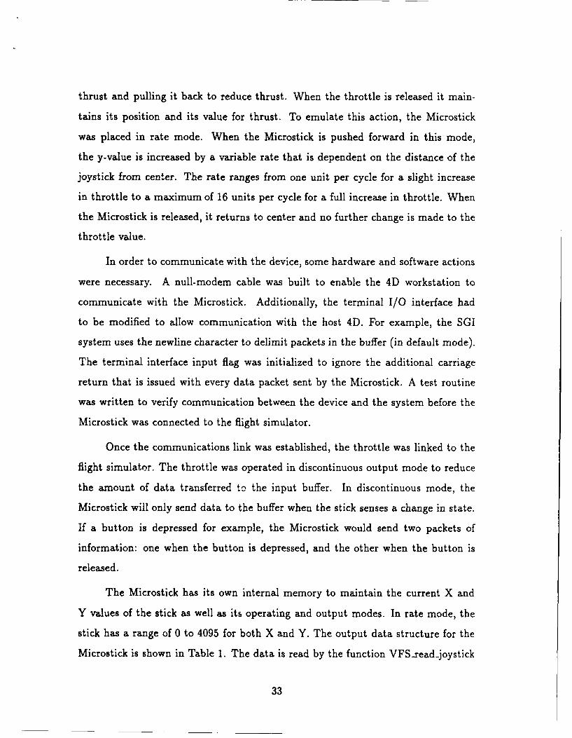
Table 1. Microstick Output Data Structure
Delim Buttoni Divider Button2 Divider Buttons Divider X-value Divider Y-value Delim
$ b b b dddd dddd CR/LF,
b = binary number d = decimal number
typedef struct
short button;short x;short y;
} JoystickData
Figure 1. Joystick Data Structure.
and placed in the data structure shown in Figure 1. Note that the button field is
only a single short value. Button2 and button3 are shifted left one and two bits
respectively and then logically or'd with buttonl to produce the button value. If
all three buttons were depressed simultaneously, the button value would be 7 while
depressing only button3 results in a button value of 4.
Capt Bob Filer built library routines for a virtual world environment, some of
which were written for the Microstick[10]. This Virtual Environment (VE) software
was used as a basis for the design of the joystick code. However, it was necessary to
modify this code to allow for real-time processing and dual joystick operation.
4.4.2 Flight Stick Controls. Implementation of the flight stick was a bit more
complicated than implementation of the throttle. Originally, the flight stick was
placed in absolute operating mode and discontinuous output mode. The flight stick
makes use of both axes to control the aircraft. When the stick is pushed to the
right, the aircraft will roll to the right, while pushing the stick to the left rolls the
aircraft left. Similarly, pushing forward on the flight stick causes the nose of the
34
aircraft to dip, while pulling back on the stick pulls the nose of the aircraft up. As
long as pressure is applied to any axis of the stick, there will be some elevation or
roll transmitted to the aircraft. The operation of the Microstick in absolute mode
closely follows the operation of an aircraft's flight stick.
In theory, the joystick should only have transmitted data when a change in state
occurred. In practice, however, the joystick continuously transmitted data because
of the noise level of the internal capacitors. The constant transfer of data caused
the input buffer to overflow which in turn produced erroneous data. This problem
caused a redesign of the flight stick I/O routines. Instead of a pseudo-interrupt
driven output, the flight stick was polled every time the main loop was executed.
The flight stick was placed in poll mode by transmitting a "?" to the Microstick (see
Table 4). Each subsequent transfer of a "?" to the Microstick signaled the joystick
to transfer another packet of data.
The Microstick still transmitted noisy data, so some sort of error correction had
to be accomplished to ensure that the aircraft responded to pilot input and not to
noise input. The Microstick has two absolute modes: absolute mode and unmapped
absolute mode (see Table 4). The x and y values for the absolute mode range from
0 to 4095 just as in rate mode. The values of x and y in unmapped absolute mode
range from 0 to 255. The Microstick was tested in both modes to determine which
was more accurate. The noise level for unmapped absolute mode was ±12 and the
noise level for the absolute mode was as much as ±270. Therefore, the unmapped
absolute mode was selected. The noise is most critical when the stick is in the center
position. In this position, no further roll or elevation should be transmitted to the
aircraft. Thus the data was clamped at the center positiou to accept inputs of no
less than 12 units from the center position.
One final comment about the flight controls concerns the rate of roll and ele-
vation. The different aircraft associated w;tn the dog software each have their own
unique constant roll and elevation rates. These rates are based upon an aircraft
35
speed of 300 knots. When the flight stick was connected to the system, the controls
appeared to be too sensitive. A second scaling factor was used to allow further ad-
justment of the roll and elevation rates. This variable could be adjusted to increase
or decrease the roll and climb rates.
4.4.3 Other Controls. Once the basic aircraft flight controls were devised,
the rest of the aircraft controls such as landing gear activation, flaps, spoilers, and
weapon delivery had to be implemented. These controls were originally operated
by depressing certain keys on the keyboard. As stated previously, all pilot controls
for the VFS had to be accomplished via the two joystick input devices. Table 2
gives a list of the controls available to the pilot and the method for selecting each
control. The rocket and missile selection buttons were only used for that purpose
to prevent accidental activation of a weapon in flight. The rest of the controls were
implemented to minimize the combinations of button depressions and stick movement
to implement each control.
4.5 Displays
The display system caused more problems than originally anticipated. The
simulator had to provide both internal cockpit views as well as out-the-window
views of other aircraft and objects within the scene. Each of these views had to
be modeled and then displayed in real-time. The displays were modeled to contain
the minimum number of objects necessary for the user to maintain the minimum
screen update rate. The objective was to get a minimum working display and then
make enhancements if time permitted.
4.5.1 Out-the- Window Displays. SGI's Flight/Dog program has two basic
display modes. The first mode is a split screen view, with an out-the-window view
in the top half of the screen and instrumentation in the bottom half of the screen.
The second view was the HUD view which gives a full-screen out-the-window view.
36
Table 2. VFS Flight Control Selection Method
Control Selection Method
Landing Gear (up/down) Throttle right button
Practice Landing Throttle left and flight stick left and right buttons
Flaps (+/-) Flight stick left button and ±throttle.x
Rudders (L/R) Flight stick right and left buttons and ±throttle.x
Spoilers (+1-) Flight stick right button and ±throttle.x
Display Help Throttle left button
Track/Lock-on Target Throttle right and left buttons
Fire Gun Throttle and flight stick left buttons
Fire Rockets Throttle middle button
Fire Missile Flight stick middle button
Autopilot Throttle right and flight stick left buttons
Restart Throttle left and flight stick right buttons
Quit Throttle and flight stick left buttons
The HUD view contains overlays of meters and gauges similar to a real aircraft HUD.
It provides the pilot with useful information about the current state of the aircraft.
The HUD display was chosen as the basis for the out-the-window views for
two primary reasons. First and foremost, a full screen view was needed because the
original view was set for a high resolution monitor with 1280 lines by 1024 pixels.
When the system is run in NTSC mode for the HMD, the number of pixels is reduced
by more than half to 640 lines by 480 pixels. The NTSC mode was important to
our display system because the head-mounted displays at the Institute were built
on standard NTSC television set technology. Second, the view provided not only
the out-the-window views but some additional information such as missile, flap, and
landing gear status as well as glide bar indicators that improved the pilot's ability
to fly the aircraft.
Although the HUD view was chosen, it did need to be modified to better
37
emulate an actual aircraft. The first modification involved the color contrast of the
HUD display. The original HUD display had yellow objects overlayed on the out-
the-window view. When the aircraft was flown during the day, this yellow color
was difficult to see against the light blue sky in the background. To solve this
problem, the color of the HUD objects was set to a darker color during the day and
remained light colored (yellow) at night. This was accomplished by checking whether
it was daylight or nighttime during initialization, and setting the color of the objects
accordingly.
A second change for the HUD involved the removal of some redundant data
that could be seen in the cockpit view. In NTSC mode the screen size is not as large
as in normal 60 Hz mode. The HUD display contained several objects that were also
contained in the cockpit front panel. To reduce the clutter of the HUD objects on
the smaller NTSC screen some objects were removed. The climb rate was one of the
objects removed because it was available in the aircraft cockpit. The G-meter was
also removed because it did not improve our feedback about the gravitational pull of
an aircraft in flight. Some information, such as altitude, thrust and bank indicators,
was kept because it proved useful to the pilot and did not detract from the pilot's
view.
The next correction involved the actual display of the HUD. In the original
program, the pilot could look around the aircraft by pressing the left or right arrows
to change the view by 90' increments. The pilot could see directly in front, to either
side, or to the rear. Further, the HUD was only displayed when the pilot was looking
to the front of the aircraft. When wearing the HMD with the Polhemus tracker, the
pilot can now look any number of degrees to the left, or right. The HUD should only
be displayed directly to the front of the aircraft. This caused a problem because the
HUD was tied to screen coordinates. Whenever the HUD was displayed, the HUD
objects were placed directly on the monitor. Due to time constraints, the HUD was
only displayed whenever the pilot was looking at the front of the aircraft. If he tilted
38
001,
Figure 2. Typical Out-the-window View of the VFS
his head up or down or turned his head to the side by more than 150, the HUD was
no longer drawn.
The final change to the HUD display was actually a completion of something
Silicon Graphics had started. The objects were not all correctly located on the
screen when the system was in NTSC mode. Several of the objects were displayed
on top of each other which made the information useless to the pilot. Still another
problem was the location of text items in the NTSC mode. The help screens were
all displayed in the wrong location and some of the information was not even visible
to the pilot. This problem was eliminated by making the calls to move the character
position relative to the actual size of the screen. Figure 2 contains a sample image
of the aircraft's out-the-window view with the HUD displayed.
39
4.5.2 Cockpit Displays. Creating the cockpit display was a three step process:
deciding on the minimum set of instruments, modeling these objects, and finally
displaying the objects in real-time.
4.5.2.1 Cockpit Makeup. The Cockpit program discussed earlier and
discussions with Lt Austin provided the basis for selecting the cockpit instrumenta-
tion[3]. In the Cockpit program a shell of a cockpit was displayed along with the
front instrument panel. The VFS cockpit instrument displays chosen were similar
in design to the Cockpit front panel instruments. The idea was to build a cockpit
shell to include a minimal set of instruments, place it inside thc aircraft, and display
the cockpit whenever the pilot looked into the aircraft. Lt Austin not only helped
determine which gauges were needed in the cockpit but also their relative position
within the front panel. Lt Austin pointed out for example that the Attitude Direc-
tion Indicator (ADI) gauge was normally placed above the heading gauge in a real
aircraft[3]. The basic cockpit display as shown in Figure 3 consisted of the following
instruments:
" Airspeed Indicator
* Thrust Indicator
" Altitude Gauge
" Rate of Ascent/Descent Gauge
" Heading Dial
" ADI
4.5.2.2 Cockpit Modeling. The F-14 and F-15 aircraft descriptions which
are identical in Flight/Dog, contained a basic cockpit frame which was used to help
construct the front panel of the cockpit. Because the plane description already con-
tained a cockpit frame, only the front panel instruments had to be created. The
40
Figure 3. Cockpit Instruments for the VFS
cockpit modeling was divided into a two-step process. Initially, the objects were
sketched onto graph paper and scaled to the proportions of the front panel of the
F-14/F-15 cockpit -hell. These sketches were then transformed into geometric de-
scriptions of the objects in the world coordinate system.
The object descriptions of the first four dials were all identical; they simply
have different transformation calls to affect their location as well as the position ol
their indicators. These dials consist of 6 components:
1. Stationary background circle
2. Stationary small hash marks (every 7.20)
3. Stationary large hash marks (every 360) and dial numbers
4. Changeable text for the value of the instrument
41
5. Stationary Reccangular box to hold the text
6. Rotating needle that points to the current value of the instrument
The heading dial and the ADI were somewhat different than the other four
cockpit instruments. These two dials were made slightly larger than the other four
dials because they were more important to the pilot[3]. In the first four indicators,
the text outputs and the rotating needles provided the effect of a working gauge.
In the heading dial, the hash marks and the letters were rotated about the center
to give the current aircraft heading. The heading indicator contained the following
objects:
1. Stationary background circle
2. Rotating small hash marks (every 100)
3. Rotating large hash marks (every 30') and direction letters (N,E,S,W)
4. Stationary inverted triangle to point out heading
The design of the ADI was more complicated than the other indicators. The
Flight/Dog code contained an ADI indicator that w,.s implemented with a two col-
ored rectangular shape under an ADI shell. The effect of an aircraft roll or climb was
achieved by rotating and sliding this rectangular section under the ADI outer shell.
The Cockpit software on the other hand, used a sphere to act as the ADI. The sphere
was rotated about two axes to provide the effect of an aircraft roll or elevation. The
rectangular implementation was originally chosen to keep the scene complexity to
a minimum. However, this design was rejected because the instruments were now
drawn inside the aircraft which precluded the use of underlays. The ADI was re-
designed for the sphere implementation. Th-s actually was an easier implementation
but it did increase the scene complexity by creating a sphere out of many polygons.
The ADI consisted of the following objects:
42
1. Stationary aircraft level indicator bar
2. Rotating attitude bars
3. Rotating top half of sphere
4. Rotating bottom half of sphere
The ADI ball was constructed of two half spheres of different colors. The
top half was blue to represent the sky and the bottom half was grey to represent
the earth. The stationary centerline is the zero elevation and zero roll line for the
aircraft. Both the ADI ball (the sphere) and the attitude lines rotate depending on
the aircraft's actual orientation with the horizon.
The geometric descriptions of the circles, spheres, and hash marks for the
instruments were all constructed using the revolve program which takes a certain
profile and 'revolves' it through a given arc to produce an object description. Circles
were produced by rotating a point and a normal through 3600 of revolution. The
coarseness of the circle is defined by the number of sections created within this
360' rotation. This coarseness determines the number of points or polygons in the
resulting geometric description. The half-spheres for example, were produced by
revolving a half-circle with 10 points spread 18' apart through 1800 with 10 sections.
4.5.2.3 Graphics Processing. Silicon Graphics created a file structure
to store object descriptions and make use of the faster graphics library routines.
These descriptions were stored in definition files ending with a '.d' suffix. SGI also
created a set of library routines to read, store, manipulate, and display the objects.
The structure of the definition files and the operation of the library routines had to
be understood before constructing the cockpit object in this form. Unfortunately,
SGI did not provide any documentation with these library routines or with the
definition files themselves. The definition file structure and the library routines
could only be understood from bench testing the code against a definition file. A
43
detailed description of the definition file structure as well as a discussion of the library
routines used in the VFS software effort is described by Dahn[9]. The definition files
contain three major components: branches, transformations, and geometry sections.
The branch sections contain a list of branches and geometry sections that form a
complete object. Each branch also contains a list of transformations that affect that
object. The transformations can be rotations, scalings, or translations while the
geometry section contains the actual geometric descriptions of each of the objects.
The cockpit geometric description was converted to SGI's definition file for-
mat for display. The primary reason for using this method was speed of processing
through the graphics pipeline. The definition file description allowed easy manipu-
lation of geometric objects by the library calls in SGI's libgobj. For example, only
one circle description was contained in the cockpit definition file. Each instance of
the background was a copy of the same object that was translated, scaled, or rotated
differently than the other dials. The library routines in libgobj, al!owed transfor-
mations to be dynamically changed during the program. Each of the rotating dials
for the first four instruments had a rotation transformation assigned to it. These
transformations were all initialized to zero in the cockpit.d file. When the airspeed
was increased, a setrotation () library call was initiated to change the rotation of the
dial to the appropriate angle. Appendix B contains a complete description of the
cockpit definition file.
Two major problems surfaced when implementing the cockpit displays. First,
the cockpit display began to shake as the aircraft was in flight. Tests revealed that
the amount of shaking was proportional to the distance the aircraft was from the
origin. Even for small distances of 2,000 to 4,000 units from the origin the cock-
pit display began to shake. The problem was tied to floating point precision. The
cockpit was being drawn immediately after the aircraft was drawn. The modeling
transformations were set up by modifying the transformation matrix. The matrix
was modified by rotations by the negative of the aircraft's orientation and transla-
44
tions by the negative of the aircraft's position. When the system's primary aircraft
was redrawn it was transformed by the opposite of the previous rotations and trans-
lations. Thus the systems primary aircraft was being needlessly transformed through
the pipeline which resulted in a floating point precision problem. To eliminate the
shaking problem of the cockpit display, the system's aircraft and cockpit were not
processed through the same transformation pipeline as the other objects.
The second problem concerned text placement. Text, such as indicator names
and indicator values, was used in the cockpit display. When the cockpit was displayed
within the aircraft, the text was not displayed in the correct location. The font size
was adjusted several times and tested to see if this would eliminate the problem; it
did not. The solution chosen was to remove the text when the pilot was looking at
the panel from a distance. The text was displayed when the full panel was brought
into the pilot's view.
4.6 Head-Mounted Display
In this section, the integration of the head-mounted display with the VFS
system will be discussed. This integration involved the connection of a Polhemus
3SPACE tracker to monitor the current pilot head position and orientation as well
as the design of software to manipulate the VFS based upon this head movement.
4.6.1 Polhemus Tracker Description. The Polhemus 3SPACE tracker con-
sists of three main components: the source unit, the sensor, and the systems elec-
tronics unit (SEU). The Polhemus tracker uses low-frequency magnetic energy to
monitor the pilot's head movement. The Polhemus can measure a full six degrees of
freedom: three for position and three for orientation. The SEU signals the source to
transmit a low frequency magnetic field which is then read by the sensor unit. The
SEU then calculates the current position and orientation based upon the deflection
of the magnetic field at the sensor[23].
45
The tracker has variable length output records that are user selectable and can
be transmitted in either binary or ASCII format. The unit also has multiple baud
rates ranging from 300 to 19,200 which can be selected by setting dip switches on
the rear of the SEU. The tracker has an RS-232 serial connection capability.
4.6.2 Hardware Integration. The Polhemus tracker was connected to an RS-
232 port on the IRIS workstation using a null modem cable to provide proper hand-
shaking between the device and the host computer. The cable was built to the
specifications listed in the Polhemus user's guide and PC Magazine's October 16,
1990 edition[23, 25]. The tracker's baud rate was set for the highest value (19,200)
to ensure the fastest possible transfer between the device and host.
Because the Polhemus tracker uses magnetic energy to calculate the pilot's
head position and orientation, the tracker's accuracy can be affected by the distance
between the source and sensor as well as metallic objects within the tracker's oper-
ating envelope. To improve the tracker's accuracy, the distance from the top of the
pilot's head to the source unit was kept below two feet. Furthermore, metal devices
were kept as far as possible from the tracker's operating envelope to reduce their
effect on the calculations.
A VFS flight station was constructed by placing the Polhemus source unit on
a fiberglass boom above the pilot's head. The sensor unit was connected to the top
strap of the HMD II using velcro. The pilot's throttle and flight stick were placed
on a small table beneath the Polhemus source unit to complete the design. Figure 4
pictures the virtual interface equipment: two Microsticks, head-mounted display,
and the Polhemus SEU.
Until the HMD III display system became available, the HMD II was used for
testing and integration. A 19 inch Sony Trinitron television set was also connected
to the output of the CIG system for testing of display fidelity and resolution because
as previously stated the HMD [I design did not meet the minimum requirements
46
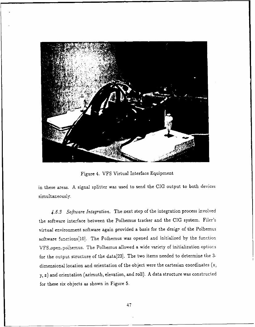
Figure 4. VFS Virtual Interface Equipment
in these areas. A signal splitter was used to send the CIG output to both devices
simultaneously.
4.6.3 Software Integration. The next step of the integration process involved
the software interface between the Polhemus tracker and the CIG system. Filer's
virtual environment software again provided a basis for the design of the Polhemus
software functions[10]. The Polhemus was opened and initialized by the function
VFS-open-)oihenus. The Polhemus allowed a wide variety of initialization options
for the output structure of the data[23]. The two items needed to determine the 3-
dimensional location and orientation of the object were the cartesian coordinates (x,
y, z) and orientation (azimuth, elevation, and roll). A data structure was constructed
for these six objects as shown in Figure 5.
47
typedef struct
float x;float y;float z;float azimuth;float elevation;float roll;
} PolhemusData
Figure 5. Polhemus Data Structure
During initialization, a boresight command was issued to initialize the sensor
orientation as the zero reference orientation point. In doing so, the pilot's head
orientation could be directly read into the Polhemus data record and used to rotate
the pilot's view. To ensure the pilot was ready before the Polhemus was initialized,
a message was displayed on the screen telling the pilot to place the HMD on his
head and when ready, press a button on either of the input devices. The routine
waited for the pilot's signal before initializing the tracker. The pilot's initial head
position was read and stored during the initialization routine for use as an offset for
future translations. Each time through the main loop, the tracker was read and the
viewing transform 'on was updated based upon the position and orientation values.
The position was subtracted from the initial head position to determine the current
position and a translation was made by this difference. The orientation values were
used to rotate the view relative to the pilot's head orientation.
4.7 Compatibility Issues
All new functions added to the system were designed to improve the system's
portability to Capt Dahn's PC based simulator. The software was written to reduce
Capt Dahn's modification of functions or library routines to a minimum.
48
Flight's communications package used the User Datagram Protocol (UDP)
and Internet Protocol (IP) rather than the more reliable TCP/IP protocol. This
protocol was not fully documented for the PC based system. An attempt was made
to connect the two systems via the UDP/IP protocol but the systems were unable
to communicate. To communicate with Capt Dahn's simulator, the communications
package would have to be rewritten. Although communications between the PC
based system and the workstation based system were not accomplished, the multi-
aircraft capability was tested against other Silicon Graphics' workstations in the
Graphics lab.
4.8 Summary
This chapter has described the entire process taken to implement the VFS
workstation based system, starting with the selection of the equipment and the rea-
sons why, to the integration of the hardware and software into a complete operational
system. Some problems arose during implementation that required redesign of that
particular portion of the system. For example, the floating point precision problem
resulted in a different and better method of displaying the user's own aircraft by
deleting redundant transformations. A complete discussion of the problems encoun-
tered in this effort as well as the results of the system will be discussed in the next
chapter.
49
V. Summary and Conclusions
The final step in this thesis effort is to discuss the virtual flight simulator (VFS)
results. Did the system meet specifications? In the following sections, a summary
of the thesis effort, the overall system results, conclusions drawn from this research,
and recommendations for future research will be discussed.
5.1 Summary
In this thesis effort, low-cost head-mounted display (HMD) technology and
a low-cost Computer Image Generation (CIG) system were combined to test the
feasibility of a virtual flight simulator (VFS) for task-specific training. The VFS
system contained the following major components:
1. Silicon Graphics IRIS 4D/85GT workstation
2. The Air Force Institute of Technology's HMD II
3. Two CH Products' Microsticks
4. A Polhemus 3SPACE tracker
5. VFS Software
Software routines were written to integrate the HMD into the virtual flight
simulator. This software monitored the pilot's head position and transferred this
information to the flight simulator to update the pilot's view. The out-the-window
views of an existing package were modified to provide realistic information for the
pilot. These views included a head-up-display (HUD) that was similar to an aircraft
HUD. A virtual cockpit was also created to increase the simulator's level of realism.
This virtual cockpit which consisted of six instruments, was placed directly inside
the aircraft model giving the pilot the illusion of a real cockpit. A new pilot interface
50
Figure 6. Virtual Flight Simulator
was created to replace the original keyboard and mouse interface. This interface used
joysticks to implement all aircraft controls. The flight simulation software was also
modified to provide a task-specific training capability.
5.2 Results and Analysis
Figure 6 pictures a user flying the virtual flight simulator. The system display
was shown on both the HMD and a 19 inch Sony Tele-ision for demonstrations. Only
one person could fly the VFS at one time but the external television allows others
to watch the action. The external television also provided a test bed for display
resolution while the HMD III was being completed.
5i
5.2.1 System Capabilities. In addition to the features originally available in
the Flight/Dog software, the virtual flight simulator has the the following capabili-
ties:
" Fully enclosed, virtual world environment totally generated by the GIG system.
" Three hundred sixty degree (full-vision) color viewing capability.
" Full six degrees of freedom for pilot head motion within the confines of the
cockpit.
" Aircraft control through two Microstick input devices.
* Virtual cockpit for the F-14 or F-15 aircraft. This cockpit contained a basic
instrument panel with airspeed, altitude, thrust, heading, Attitude Direction
Indicator (ADI), and rate of descent. These aircraft were chosen to host the vir-
tual cockpit because they were the best geometric models in SGI's Flight/Dog
software.
" Head-up-display (HUD) view while the pilot is looking toward the front of the
cockpit.
" Practice landing capability to provide a task-specific training environment for
the VFS. By selecting the landing option, the aircraft is reset to a final approach
position.
5.2.2 Frame Update Rate. The most critical performance issue for the VFS
system was the screen display update rate. According to Brooks, the minimum frame
update rate for "realistic illusion" is 20 to 30 frames per secondl6]. The requirement
for the VFS system was to achieve a minimum of 15 frames per second. The update
rate was measured to determine the effects of different configurations on the rate as
well as the effect of multiple users communicating across the network.
52
5.2-2.1 Configuration Measurements. The system display update rate
was measured under several configurations to help determine any limiting factors.
The VFS was operated in both NTSC and standard mode on two different SGI IRIS
workstations: the 4D/85GT and a 4D/320VGX system that was on loan to the
Institute. Table 3 lists the screen update rate under various configurations.
Table 3. Display Update Rates
System 4D/85GT 4D/320VGX
Configuration NTSC Standard NTSC Standard
Original Code Min 11 5 14 7
Original Code Max 15 12 20 15
Original Code Typical 14/15 9/10 19/20 15
With Flight Controls Min 10 5 14 7
With Flight Controls Max 15 12 20 15
With Flight Controls Typical 14/15 9/10 19/20 15
With Cockpit Displays Min 8 5 11 7
With Cockpit Displays Max 12 10 15 13
With Cockpit Displays Typical 10/11 8 15 12
Complete VFS System Min 8 5 11 7
Complete VFS System Max 12 10 15 14
Complete VFS System Typical 10/11 8 15 12
The original Flight/Dog code provided the baseline for the system's perfor-
mance. All tests were performed with the user's aircraft displayed which is the
default for the VFS system. However, this was the wingman view option in the
original code. It should also be noted that the test configurations were incremental;
that is, each stage included the configuration of the previous stage.
The more powerful 4D/320VGX system had a much better update rate than the
4D/85GT. The VGX system provide, .lhe minimum frame update rate of 15 frames
per second required for the system. The update rate was dependent upon the number
53
of pixels being drawn. The standard full-screen display mode had significantly lower
update rates for all configurations. The same number of polygons were processed and
displayed each time; the only difference was the screen size. The standard screen size
was 1280 by 1024 while the NTSC screen size was 640 by 480. Another observation
was that the display rate was dependent upon the complexity of the objects within
the pilot's view. The maximum update rate occurred when the background color
encompassed the entire screen. The minimum rate occurred when looking back at
the user aircraft which contained nearly 1200 polygon structures.
The most significant decrease in the update rate occurred when the cockpit
displays were added to the system. The decrease was directly related to the com-
plexity of this object. The cockpit was described by 422 polygons and lines as well
as a small number of text characters. This object, which is nearly half the size of the
F-14/15 itself, was displayed every time the main loop was executed. The change in
the update rate was inversely proportional to this change in complexity. It should
also be noted that even if only a small portion of the cockpit was displayed in the
scene, the update rate was reduced. This reduction in rate was the result of process-
ing the structure through a portion of the graphics pipeline before clipping it from
the view.
One final comment about screen update rate concerns device communications.
The data in Table 3 indicated that device I/O had little or no affect on system
performance. The joysticks and the Polhemus tracker did not reduce the screen
display throughput. Keyboard input, on the other hand, did affect the update
when many keystrokes were in the device queue. In the original code the update
rate would vary by one or two frames per second when the system queue received
multiple entries. This reduction was not as prevalent while using the flight stick and
throttle to control the aircraft.
54
5.2.2.2 Multiple User Measurements. The display update rate was also
tested to determine the affects of multiple users on the system. Multiple users did
affect the display rate in one critical area: scene complexity. As other aircraft came
into view, the scene complexity increased and the update rate was reduced. The
effect became more noticeable as the other aircraft came closer to the user's aircraft.
This was a result of Silicon Graphics descriptions of the F-14/15. They have different
structures for the aircraft depending on the distance from the user's eye. The plane
definition files had both near and far objects; the near objects were more complex
than the far objects to reduce the number of polygons passed through the graphics
pipeline. When the other aircraft were further away, the decrease in update rate was
negligible.
5.2.3 Display Systems. Due to delays beyond the author's control, the HMD
III system was not available for use in this thesis effort. Because the displays
were designed for the resolution of a standard NTSC television, two output de-
vices were needed to determine the quality of the images displayed as well as the
reality achieved. The output display was tested on the AFIT HMD II system and a
Sony Trinitron, 19 inch television set.
The HMD II was used for testing the virtual reality concept of the VFS system.
The HMD Il and the Polhemus tracker gave the pilot the ability to change his view
by simply moving his head. The pilot could look down into the cockpit and see
his instrument panel or he could turn his head and see the aircraft wings. The
main drawback of the HMD II was the resolution. The cockpit display, the head-
up-display, and all system text messages were not readable using the HMD II. This
made it difficult to determine the aircraft's status during flight. Practice landings,
for example, were difficult to accomplish without knowing the aircraft's climb rate
and landing gear status.
The Sony 19 inch television set relieved some of the resolution problems for
55
testing the displays. The cockpit displays and help screens were designed for use on
a screen with standard NTSC resolution: 640 by 480. The cockpit and HUD displays
as well as all text displays were readable on the Sony TV. However, this solution did
not solve the limited resolution in the virtual world environment.
5.2.4 Human Factors. It is impossible to quantify the results concerning hu-
man factors for the VFS system. The two main concerns with human factors were
the enclosed HMD design and the response of the system to pilot action. The en-
closed system design thrust the pilot into the virtual world environment. Because an
enclosed system was used the controls were not visible to the pilot. Thus the pilot
was forced to select aircraft controls 'in the dark', while relying on visual feedback
from the VFS that the desired control had been activated. As for the second con-
cern, the system responded well to all flight controls. There was a slight adjustment
period to allow the pilot time to get the 'feel' of the controls as well as the selection
process for each control.
Another human factor involved the system response to pilot head movement.
As the pilot turned his head, there was a small delay between the actual head
movement and the reaction of the movement in the display. However, this problem
was not believed to be critical for this effort. The lag was only noticeable during
rapid head motion.
5.2.5 Network Communications. The Flight/Dog software used the User Data-
gram Protocol for communicating between multiple aircraft. The PC based system
and the workstation based system could not communicate using this protocol. Be-
cause of time constraints, the software was not rewritten to use the Transport Control
Protocol to attempt to connect these systems. However, the other SGI workstations
did provide a test-bed for flying multiple aircraft missions against the workstation
based VFS.
56
5.2.6 Problems Encountered. Silicon Graphics constrained the HUD by tying
the display to screen coordinates. This reduced the realism factor because the HUD
was displayed from all views and all angles. The HUD was further constrained within
the VFS by only displaying the image while the pilot was looking towards the front
of the plane. This solution reduced but did not eliminate the original problem.
The use of text in the virtual cockpit created a problem whenever the pilot
rotated his head. Text is always written horizontally to the screen. When the pilot's
head and view are rotated, the text is positioned at the correct location for drawing
but the orientatiun is incorrect. To reduce this problem, the text portion was only
written on the cockpit when the pilot had the complete cockpit view in front of his
eyes.
5.3 Conclusions
The goal of this effort was to test the concept of coupling a virtual world en-
vironment and a flight simulator while maintaining "low-cost". The virtual flight
simulator was inexpensive when compared to multi-million dollar systems that have
been developed in the past. The SGI 4D/85GT with educational discount was less
than $35,000. This system did not provide the minimum update resolution of 15
frames per second but that does not preclude its ability to act as the host for a
virtual flight simulator. On the other hand, the more powerful and slightly more
expensive SGI 4D/320VGX system did provide a sustained update rate of 15 frames
per second. Based upon these results, a graphics workstation can provide the per-
formance necessary for a flight simulator.
Although the resolution of the HMD II was below the minimum required, it
did provide the user with enough visual cues to produce the 'feel' of flight. The out-
the-window displays were clear enough to allow for practice take-offs and landings.
The NTSC resolution of the Sony Television did provide quality images for the
system. Because the next generation HMD III is expected to have the resolution of
57
an NTSC TV Iit should eliminate the resolution problem of the HMD II and provide
a foundation for a part-task virtual flight simulator.
The system's response to head movement was considered acceptable. The
system lag time, which was most noticeable during rapid pilot head movement, had
little effect on pilot control of the aircraft. Lag times of more than 150 ms have been
shown not to cause pilot difficulty[36]. Had the system been designed for combat
training, where the pilot would need to turn his head rapidly, then a head movement
prediction algorithm as discussed by List could be used to reduce this lag[19].
Several conclusions can be made concerning the flight controls. The joysticks
did improve the realism of the simulator as well as the feel of flight. As with any new
system there was an adjustment period to learn the new controls as well as the sensi-
tivity of the controls. This adjustment period was considered normal. The selection
of some controls was awkward for two reasons. First, selections were made without
visual confirmation because the controls were not visible to the pilot. Second, the
location of two of the buttons on the base of the Microstick made it difficult to select
controls that required multiple button depressions.
The problems discussed in the previous section reduced the level of realism of
the simulator. The solutions were successful in improving the reality of the model,
but they were not the best solution to improving the system's reality. To use text
in a virtual environment, the text font display routines would have to be rewritten
to overcome screen dependency.
5.4 Recommendations for Future Research
The following recommendations are suggested for future research:
1. Implement the SIMNET protocols for the VFS so that the system can be con-
nected to the U. S. Army's SIMNET combat simulator. The implementation of
SIMNET protocols could provide the ability for inter-service training exercises.
58
By implementing the SIMNET protocols, the HMD could also be used by tank
commanders to dismount their tanks to look over a nearby hill all within the
confines of a virtual world. The HMD with SIMNET protocols could also be
used as a 'stealth' controller station so that a controller could watch the battle
from anywhere in the battlefield including an aircraft or tank.
2. Integrate the VPL Dataglove into the VFS to provide a hand-eye coordinated
selection system for aircraft controls other than the throttle, azimuth, eleva-
tion, and roll. This would involve creating virtual switches that the pilot could
select using the Dataglove. The selection could also be based upon some tactile
feel that the switch was activated. Some of the controls that could be selected
are: flaps, landing gear, and target tracking and lock-on.
5.5 Closing Comments
In this thesis, a low-cost head-mounted display and a low-cost graphics engine
were coupled to provide a virtual flight simulator. Though no statistical data were
collected on the value of this system, the results indicate the concept has its mer-
its. The system met all requirements except for the screen update rate. The VFS
system's sustained update rate of 10/11 frames per second though not the minimum
required, did provide the "illusion" of real flight. The display frame update rate
measurements confirmed that a more powerful system could provide this minimum
update rate. The system also had the ability to fly multiple aircraft in formation
or dog-fight mode via an Ethernet network. Although the next generation head-
mounted display, HMD III, was not available for this thesis effort, the coupling of
the HMD II with the VFS software provided enough justification to show that the
overall concept was valid. Inclusion of the next generation HMD III should pro-
vide further insight into the overall value of this system. The answer to the thesis
statement is yes, a low-cost virtual flight simulator can be achieved.
59
Appendix A. Microstick Description
CH Products' Microstick is a 2-dimensional input device with RS-232 connec-
tivity and an external 5 volt power supply. It has seven modes of operation and
three output modes (see Table 4). The Microstick has a maximum resolution of
4095 by 4095. The resolution is dependent upon the operating mode selected. The
unmapped absolute mode has a resolution of 256 by 256 while the absolute mode
has the maximum resolution. The three output modes control the timing of the
data transmitted by the device. The first output mode continuously transmits data
while the second output mode only transmits when there is a change in the status
of the device. The final mode puts the device in a polled mode for transmitting
data; whenever the computer signals the joystick to transmit, it transmits a packet
of data. Except for the computer requested output mode, all modes can be selected
by either setting the mode dip switches or sending the appropriate character to the
Microstick.
The Microstick handles standard ASCII characters as input and output[7]. The
device also has multiple baud rates ranging from 300 to 19,200 baud. The baud rate
is selected in the hardware by setting the appropriate baud rate dip switches (see
Table 5).
60
Table 4. Operating/Output Modes for the Microstick
Mode Switch Mode Selected Software Selection Character
00OX Rate-Absolute mode 0
001X Zoom-Absolute Mode 1
01oX Unmapped-Absolute Mode 2
MIX Rate Mode 3
10oX Zoom Mode 4
101X Absolute Mode 5
lloX Mouse Mode 6
iliX Bit-Pad Mode 7
XXXO Continuous Output c
Xxxi Discontinuous Output d
NONE Computer Requested Output ?
Table 5. Baud Rates for the Microstick
Baud Rate Switch Baud Selected
1000 19200
0100 9600
0010 1200
0001 300
61

Appendix B. Cockpit Description
To increase the virtual flight simulator's level of reality, a virtual cockpit was
developed. This appendix describes the cockpit definition file containing the geo-
metric descriptions of the virtual cockpit.
B. 1 Modeling
The virtual cockpit was created using Silicon Graphics' definition file format.
Any object can be created in this format. The file contains a list of branches,
geometric descriptions, and transformations that act upon a branch. A complete
description of the definition file format can be found in Capt Dahn's thesis[9]. The
basic format of the definition file is as follows:
" Number of Branches
" List of Branches with the following format:
- Statebits, modebits
- Number of transformations, list of transformations affecting this branch
- Number of branches or geometry sections within this branch, List of these
branches and geometry sections
" Number of transformations
* List of transformations with following format:
- Transformation type, transformation data
* Number of geometry sections
" List of Geometry containing following format:
- Type of geometric object (line, polygon, shaded, flat, etc.)
62
- Color of object
- Number of points in the object
- List of these points
- Number of polygons in this geometry section
- List of points that form these polygons
Note that there are several formats for the geometry sections, the one shown
was used in the virtual cockpit definition file.
B.2 Cockpit Description
There were nineteen branches, twenty-one transformations, and 16 geometry
sections in the cockpit description. The first branch which represents the whole
instrument panel, has one translation to the front of the F-14/15 cockpit. The
instrument panel was formed from branches 1, 2, 3, 4, 6, 8, and 9; one branch for
each of the six instruments plus a triangle that points to the current heading. Table 6
provides a complete list of the 19 branches within the cockpit definition file:
Silicon Graphics' library, libgobj, contains routines to read, draw, and manip-
ulate objects described in their definition file format. The readobj routine reads the
data structure into memory and the drawobj routine processes the structure through
the graphics pipeline. Movement of dials is accomplished by using the setrotation
routine. The dial of each instrument contains a separate rotation transformation to
affect the position of the dial during flight. The airspeed is read from the plane's
data structure, the values are converted to d'grees and the setrotation function is
executed. Each dial needs itt. own transformation because the function drawobj will
draw the entire cockpit in one function call. The last transformation will change the
actual value of this transformation in memory and cause any object affected by this
transformation to be changed.
63
Table 6. Cockpit Branch Descriptions
Branch Number Description
BO Cockpit Instrument Panel
B1 Altitude Instrument
B2 Ascent/Descent Rate Instrument
B3 Airspeed Instrument
B4 Thrust Instrument
B5 Heading Hash Marks and Letters
B6 Attitude Direction Indicator (ADI)
B7 ADI Hash Marks
B8 Heading Triangle
B9 Heading Instrument and Hash Marks
B10 ADI Outline and Center Bar
B 11 Altitude Dial
B12 Ascent/Descent Rate Dial
B13 Airspeed Dial
B14 Thrust Dial
B15 Top Half of ADI Sphere
B16 Bottom Half of ADI Sphere
B17 Short Altitude Dial
B18 Short Ascent/Descent Rate Dial
The geometry objects can be reused by several different branches. Four of
tL - six instruments use the basic blue circle as background for the dial. The two
exceptions were the ADI which was created with a sphere and the Ascent/Descent
rate dial which used Uifferent colors depending on the aircraft's descent rate. The
blue dial was used while climbing, a green dial was used while descending at a safe
rate for landing, and a red dial was used when falling faster than this safe rate (600
fpm). This effect was accomplished by manipulating the color of the structure in
memory before drawing the object.
64
All branches, transformations, and geometry sections are referenced from zero
to n - 1, where n is the number of branches, transformations, or geometry sections.
Furthermore, branch numbers start with a 'B' followed by the branch number (BO,
for example). Similarly, geometry sections begin with a 'G' and are followed by
the geometry section number (G12, for example). Lists of data such as vertices are
separated by commas and comments are delimited using the # symbol.
65
Bibliography
1. Allen, John H. and Richard C. Hebb. Helmet Mounted Display FeasibilityModel. Technical Report NAVTRAEQUIPCEN IH-338, Naval Training Equip-ment Center, Orlando FL 32813: Advanced Simulation Concept Laboratory,February 1983.
2. Alluisi, Earl A. Image Generation/Display Conference II, 10-12 June 1981:Closing Comments. Technical Report, Air Force Human Resources Laboratory,1981. AFHRL-TP-81-28.
3. Austin, Mark. 1st Lt, USAF. Personal Interview. Detachment 2, 1401 MAS,Wright-Patterson AT t' OH, August 1990.
4. Breglia, Denis R. "On-Board Computer Image Generator (CIG) Applications."In 1984 IMAGE III Conference Proceedings, pages 431-437, 1984. DTIC AD-P004 335.
5. Brooks, Frederick P. and others. "Project GROPE - Haptic Displays for Sci-entific Visualization," Computer Graphics, 24:177-185 (August 1990). SIG-GRAPH '90 Proceedings, August 6-10, Dallas TX.
6. Brooks, Jr., Frederick P. Grasping Reality Through Illusion - Interactive Graph-ics Serving Science. Technical Report, University of North Carolina at ChapelHill, Mar 1989.
7. CH Products, 1558 Osage Street San Marcos, CA 92069. The Microstick User'sManual Version 0.1, 1985.
8. Cook, Lt Col Peter A. and Capt Caroline L. Hanson. "Training The Multiple-Aircraft Combat Environment." In Interservice/Industry Training EquipmentConference (5th), Nov 1983.
9. Dahn, David A. A Low-Cost Part-Task Flight Training System: An Applicationof a Head Mounted Display. MS thesis, Air Force Institute of Technology, 1990.
10. Filer, Robert E. A 3-D Virtual Environment Display System. MS thesis, AirForce Institute of Technology, 1989.
11. Geltmacher, Hal E. Recent Advances in Computer Image Generation Simu-lation. Aviation, Space, and Environmental Medicine 59, Air Force HumanResources Laboratory, Williams AFB, November 1988.
12. Gorey, Kevin B., "Periodic Table of IRISes," July 1990. Silicon Graphics SalesFlash.
13. Haber, Ralph Norman. "Flight Simulation," Scientific American, 255:96-103(July 1986).
66
14. Hanson, Capt Caroline L. "Fiber Optic Helmet Mounted Display: A CostEffective Approach to Full Visual Flight Simulation." In Proceedings of the In-terservice/Industry Training Equipment Conference (5th) Held at Washington,DC, pages 262-268, November 1983. DTIC AD-P003 482.
15. Hughes, Ronald G. and Capt Larry Brown. Trends Shaping Advanced AircrewTraining Capabilities Through the 1990s. Technical Report AFHRL-TP-84-52/DTIC AD-A152 277, Air Force Human Resources Laboratory, OperationsTraining Division, March 1985.
16. Kandebo, Stanley W. "USAF Controllers, F-15 Pilots Train for Combat UsingMultiship Simulation," Aerospace Week and Space Technology, 130(13):71-79(Mar 1989).
17. Kolcum, Edward H. "Growing Flight, Simulation Market Attracts Many Com-petitors," Aerospace Week and Space Technology, 130(1):91-93 (Jan 1989).
18. Lee, A. T. and I. G. Lidderdale. Visual Scene Simulation Requirements for C-5A/C-141B Aerial Refueling Part Task Trainer. Technical Report, Air ForceHuman Resources Laboratory, 1982. AFHRL-TP-82-34.
19. List, Uwe H. Nonlinear Prediction of Head Movement for Head-Mounted Dis-plays. Technical Report AFHRL-TP-83-45, Air Force Human Resources Labo-ratory, December 1983.
20. Lorimor, Gary K. Real-Time Display of Time Dependent Data Using a Head-Mounted Display. MS thesis, Air Force Institute of Technology, 1988.
21. Measurement Systems, Inc., "Positioning and Tracking Controls Catalog andPrice List," December 1987.
22. Nordwall, Bruce D. "Computer-Based Training Role Grows in Pilot Instruc-tion," Aerospace Week and Space Technology, 128(24):113-118 (June 1988).
23. Polhemus Navigation Sciences Division Mcdonnell Douglas Electronics Com-pany. SSPACE User's Manual, January 1985.
24. Pope, Authur R. The SIMNET Network and Protocols. Technical Report BBNReport No. 7102, BBN Systems and Technologies, Cambridge Ma., July 1989.
25. Prosise, Jeff. "Null-Modem Cables," PC Magazine, 9(17):497 (October 1990).
26. Rebo, Robert Keith. A Helmet-Mounted Virtual Environment Display System.MS thesis, Air Force Institute of Technology, 1988.
27. SIGGRAPH'90 Conference Proceedings. (Dallas, Texas, August 6-10 1990).
28. Silicon Graphics Computer Systems. Porting A;,plications to the IRIS-4D Fam-ily, 1988. Version 1.1.
29. Silicon Graphics, Inc., "Silicon Graphics Input Device Vendor Listing," June1989.
67
30. Smith, Douglas Bernard and Dale Gerard Streyle. An Inezpensive Real-TimeInteractive Three-Dimensional Flight Simulation System. MS thesis, NavalPostgraduate School, June 1987.
31. Sutherland, Ivan E. "A head-mounted three dimensional display." In 1968 FallJoint Computer Conference, AFIPS Conference proceedings, pages 757-764,1968.
32. Unknown Author. "Costs, Limits of Flight Training Prompt Firms to IncreaseSimulator Use," Aerospace Week and Space Technology, 129(16):59-62 (Oct1988).
33. Unknown Author. "SGI Unveils New Iris," The Sun Observer, 3(4):3 (Apr1990).
34. "VPL Research, Putting Virtual Reality to Work Today!," 1990. VPL ProductAnnouncement.
35. Wardin, Charles L. Battle Management Visualization System. MS thesis, AirForce Institute of Technology, 1989.
36. Woodruff, Robert R. and others. Advanced Simulator for Pilot Training andHelmet-Mounted Visual Display Configuration Comparisons. Technical ReportAFHRL-TR-84-65/DTIC AD-A155 326, Air Force Human Resources Labora-tory, Operations Training Division, May 1985.
37. Zyda, Michael J., et al. "Flight Simulators for Under $100,000," IEEE Com-puter Graphics &1 Applications, pages 19-27 (January 1988).
68
Vita
Captain Philip A. Platt was born July 9, 1954, in Queens, New York. Af-
ter graduating from Cathedral Preparatory Seminary High School, he entered the
Air Force in August 1972. He served as an aircraft armament systems specialist
until 1982 when he was selected for the Air Force's Airman's Education Z_ d Com-
missioning Program (AECP). He graduated magna cum laude from Arizona State
University with a degree in Electrical Engineering in 1985. His first assignment
was to Tinker AFB Ok, where he was assigned as a programmer analyst for the
Engineering Installation Division (EID). His duties at the EID progressed from tech-
nical support for the Division's small computer technical center, to lead programmer
for the EID's Engineering Installation Management System database, and finally to
Chief of the Division's data processing center. In this capacity, he was responsible
for equipment and programming support for the EID's 7 active duty and 19 Air
National Guard units. In 1988 he was transferred to the Command and Control
Systems Office (CCSO) to help develop a new Ada communications system. While
assigned to CCSO he became involved in program management of the unit's future
Milstar satellite software maintenance effort. In May 1989 he entered the School of
Engineering at the Air Force Institute of Technology (AFIT).
Permanent address:73 Meserole AvenueBrooklyn, New York 11222
69
Form ApprovedREPORT DOCUMENTATION PAGE MB No 004-0188
S).'- !e.~ $.' 2:4 .; : A 222243C2 acTh !c " t- D 3e~~~- )~A33 .~~
1. AGENCY USE ONLY (Leave blank) 2. REPORT DATE 3. REPORT TYPE AND DATES COVEREDDecember 1990 Master's Thesis
4. TITLE AND SUBTITLE 5. FUNDING NUMBERS
Real-Time Flight Simulation and the Head-Mounted Display -An Inexpensive Approach to Military Pilot Training
6. AUTHOR(S)
Philip A. Platt, Capt, USAF
7. PERFORMING ORGANIZATION NAME(S) AND ADDRESS(ES) 8. PERFORMING ORGANIZATIONREPORT NUMBER
Air Force Institute of Technology, WPAFB OH 45433-6583 AFIT/GCS/ENG/90D-11
9 SPONSORING MONITORING AGENCY NAME S) AND ADDRESS(ES) 10. SPONSORING MON'TORiNGAGENCY REPORT NUMBER
11. SUPPLEMENTARY NOTES
12a DISTRIBUT;ON AVAILABILiTY STATEMENT 12b DISTRIBUTION CODE
Approved for Public Release; Distribution Unlimited.
13. ABSTRACT M'rn 2C'.:ri;
Abstract
The integration of the low-cost head-mounted display (HMD), an inexpensive graphics workstation-basedflight simulator, and a communications network was investigated to determine if the prototype of an inex-pensive multi-aircraft Virtual Flight Simulator (VFS) could be built. Previous research efforts have coupledHMD technology and flight simulation; however, the cost of these systems has been high. This thesis effortemphasized the use of joystick devices to emulate pilot control, the implementation of a fully enclosed virtualflight simulator, and the utilization of low-cost NTSC-based television technology to produce a prototype.
The virtual flight simulator also contained a basic set of instruments to help the pilot control the aircraft.The virtual world provided a full color 360 degree viewing capability which allowed the pilot to look around
his aircraft and world. Although the display update rates of the final system were less than ideal, the resultsshowed that the concept of virtual flight simulators has potential for improving the Air Force's overall pilottraining capability.
14 SUBJECT TERMS 15 NUMBER OF PAGES
Virtual World Environments, Head-Mounted Displays, Low-Cost Flight Simulation 7916. PRICE CODE
17. SECURITY CLASSIFICATION 18 SECURITY CLASSIFICATION 19 SECURtTY CLASSIF:CATIO" 20. LIMITATION OF ABSTRACTOF REPORT OF THIS PAGE OF ABSTRACT
UNCLASSIFIED UNCLASSIFIED UNCLASSIFIED UL
NSN "S0-... ... ... .. .. .. .. .. .. .. .. .. ... :.