Embed Size (px)
Citation preview
Abstract
IntegrAL® thick-film heaters by Datec Corporation produce exceptionally fast, precise, uniform and efficient heat in a low-profile footprint. IntegrAL thick-film heater is printed directly onto an aluminum substrate. By combining the excellent thermal properties of aluminum with a high watt density thick-film heating circuit results in better response, uniformity, efficiency and precision than contemporary heating technologies. Many commercial and industrial applications use discrete electric heaters to provide controlled localized distributed heat to maintain temperatures within fixed limits. This report describes an experimental investigation comparing the performance characteristics of the IntegrAL heater with a polyimide insulated etched foil heater, silicone rubber insulated wire heater, and cermet thick-film heater when used in a common commercial heating application.
Thick-Film Heater achieves Superior Performance in Thermal Response, Uniformity and Efficiency. by Mary Ruggiero, P.Eng., PhD and John Stockton, P.Eng
2 Datec Corporation
Executive Summary
Comparative performance characteristics of four competitive heating technologies were tested
on a common commercial heating platen for:
1) Thermal response time
2) Temperature uniformity
3) Thermal efficiency
The heating technologies used for comparison purposes were polyimide (Kapton®) heater,
silicone rubber wire wound heater and ceramic metal (cermet) heater. Under this test
protocol, IntergrAL thick-film provided the most uniform temperature profile with a maximum
temperature variation of 3.8⁰C, followed by the silicone rubber heater at 6.7⁰C and polyimide
insulated heater at 12.4 ⁰C variation, and then a very distant fourth the cermet heater with
maximum temperature variation exceeding 45.1 ⁰C.
Similarly, response time for the IntegrAL heater to bring the platen to 140°C from room
temperature was faster than polyimide, silicone rubber heaters and cermet by 14%, 27% and
20%, respectively. The IntegrAL heater also demonstrated better thermal efficiency as well as
the combination of its low-profile, low-mass, uniformly distributed heating circuit with
aluminum’s high thermal conductivity provided the lowest temperature variation and highest
speed.
IntegrAL heater exploited the intimate contact between the heat generating coating and the
aluminum platen to maximize heat transfer into the platen over a larger area while holding a
lower element temperature relative to the working surface of the platen and the ambient. This
lower element temperature minimized thermal losses to the environment compared to each of
the other heaters. This intimate contact and lower temperature differential between the heat
generating layer and the aluminum substrate is one of the reasons that the IntegrAL thick-film
heater can sustain high watt densities up to 23W/cm2 (150W/in2) at temperatures up to 250°C.
Due to manufacturing process constraints, cermet heaters must be printed on materials with
compatible thermal expansion coefficients, namely ferritic stainless steels. The poor thermal
conduction of ferritic stainless steel requires the cermet heater to operate at a much higher
temperature in order to drive the heat into the platen, thereby incurring significant ambient
losses. Similarly, but to a lesser extent, the silicon rubber heater, by its design, must generate a
significant temperature gradient to drive heat through the silicone rubber wall. This high
temperature leads to losses through the non-working side of the element.
3 Datec Corporation
Heated Platen Test | Detailed Report
Introduction
The tests conducted for this report were designed to compare the performance characteristics of four different heating technologies used in a common commercial heating application. The heating technologies reviewed in this study were:
1) Composite sol-gel thick-film IntegrAL heater deposited onto 5.3mm aluminum plate 2) Polyimide insulated etched foil heater adhered to 5.3mm aluminum plate using a PSA
adhesive 3) Silicone rubber heater fixed on 4.75mm aluminum plate 4) Ceramic metal (cermet) thick-film heater on 2mm ferritic stainless steel (SS430) (The
substrate is different due to the inability to apply cermet technology to aluminum)
The primary performance characteristics with regards to integration of heaters for a wide-range of applications were identified as thermal response, uniformity and efficiency.
The purpose of the experiment was to compare the following performance characteristics of the selected heating technologies:
1) Thermal Response (time to achieve operating temperature) 2) Temperature Uniformity (temperature variation across the heated platen) 3) Thermal Efficiency (% of energy transferred to the heated object)
An aluminum platen geometry of 146mm x 292mm (5 ¾ “ x 11 ½ “) was selected because this was a commonly available commercial heated base with available dedicated polyimide, silicone rubber and cermet heaters readily available for testing.
The heaters were nominally rated at 120V 200W and were corrected to provide uniform power within 1.5% of nominal during testing. Because the heating elements were slightly different in power, substrate thermal conductivity, and substrate thermal capacity ( Joules/⁰C temperature rise) it was decided to conduct the heating tests at similar power and set-up, and heat them through a similar temperature schedule while measuring input power, time and temperature.
In addition, thermographs for each heater technology were acquired to provide visual and temperature distribution data.
4 Datec Corporation
Procedure
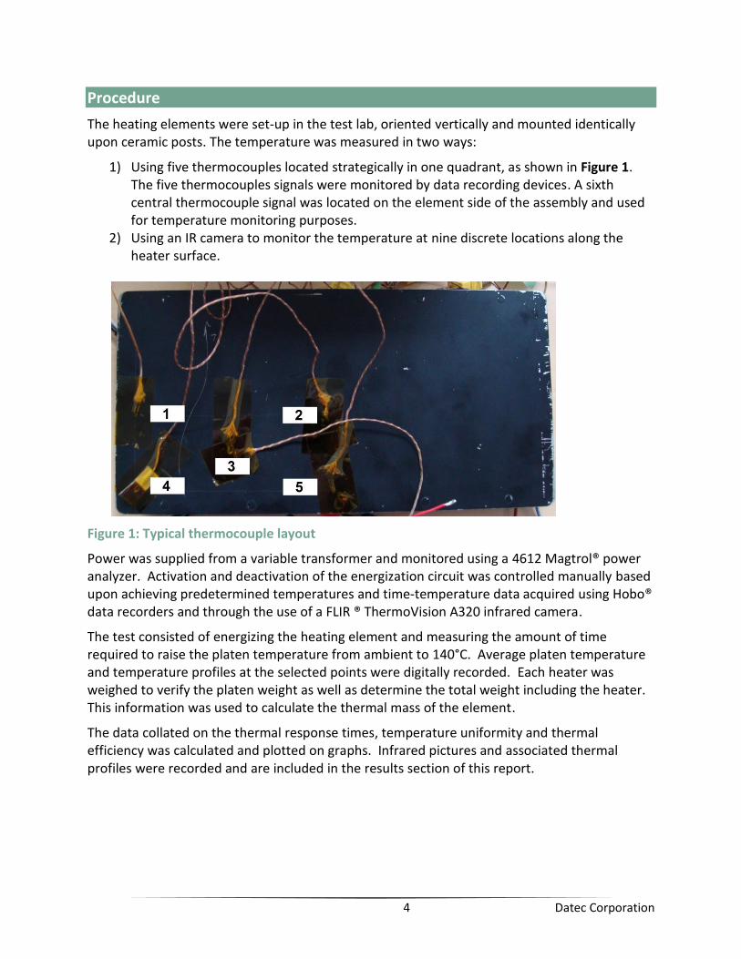
The heating elements were set-up in the test lab, oriented vertically and mounted identically upon ceramic posts. The temperature was measured in two ways:
1) Using five thermocouples located strategically in one quadrant, as shown in Figure 1. The five thermocouples signals were monitored by data recording devices. A sixth central thermocouple signal was located on the element side of the assembly and used for temperature monitoring purposes.
2) Using an IR camera to monitor the temperature at nine discrete locations along the heater surface.
Figure 1: Typical thermocouple layout Power was supplied from a variable transformer and monitored using a 4612 Magtrol® power analyzer. Activation and deactivation of the energization circuit was controlled manually based upon achieving predetermined temperatures and time-temperature data acquired using Hobo® data recorders and through the use of a FLIR ® ThermoVision A320 infrared camera.
The test consisted of energizing the heating element and measuring the amount of time required to raise the platen temperature from ambient to 140°C. Average platen temperature and temperature profiles at the selected points were digitally recorded. Each heater was weighed to verify the platen weight as well as determine the total weight including the heater. This information was used to calculate the thermal mass of the element.
The data collated on the thermal response times, temperature uniformity and thermal efficiency was calculated and plotted on graphs. Infrared pictures and associated thermal profiles were recorded and are included in the results section of this report.
5 Datec Corporation
Results
Thermal Response
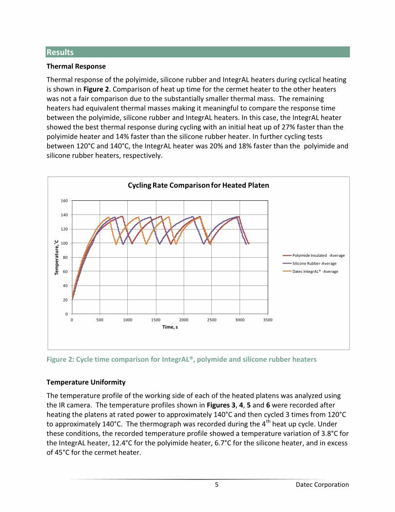
Thermal response of the polyimide, silicone rubber and IntegrAL heaters during cyclical heating is shown in Figure 2. Comparison of heat up time for the cermet heater to the other heaters was not a fair comparison due to the substantially smaller thermal mass. The remaining heaters had equivalent thermal masses making it meaningful to compare the response time between the polyimide, silicone rubber and IntegrAL heaters. In this case, the IntegrAL heater showed the best thermal response during cycling with an initial heat up of 27% faster than the polyimide heater and 14% faster than the silicone rubber heater. In further cycling tests between 120°C and 140°C, the IntegrAL heater was 20% and 18% faster than the polyimide and silicone rubber heaters, respectively.
Figure 2: Cycle time comparison for IntegrAL®, polymide and silicone rubber heaters Temperature Uniformity
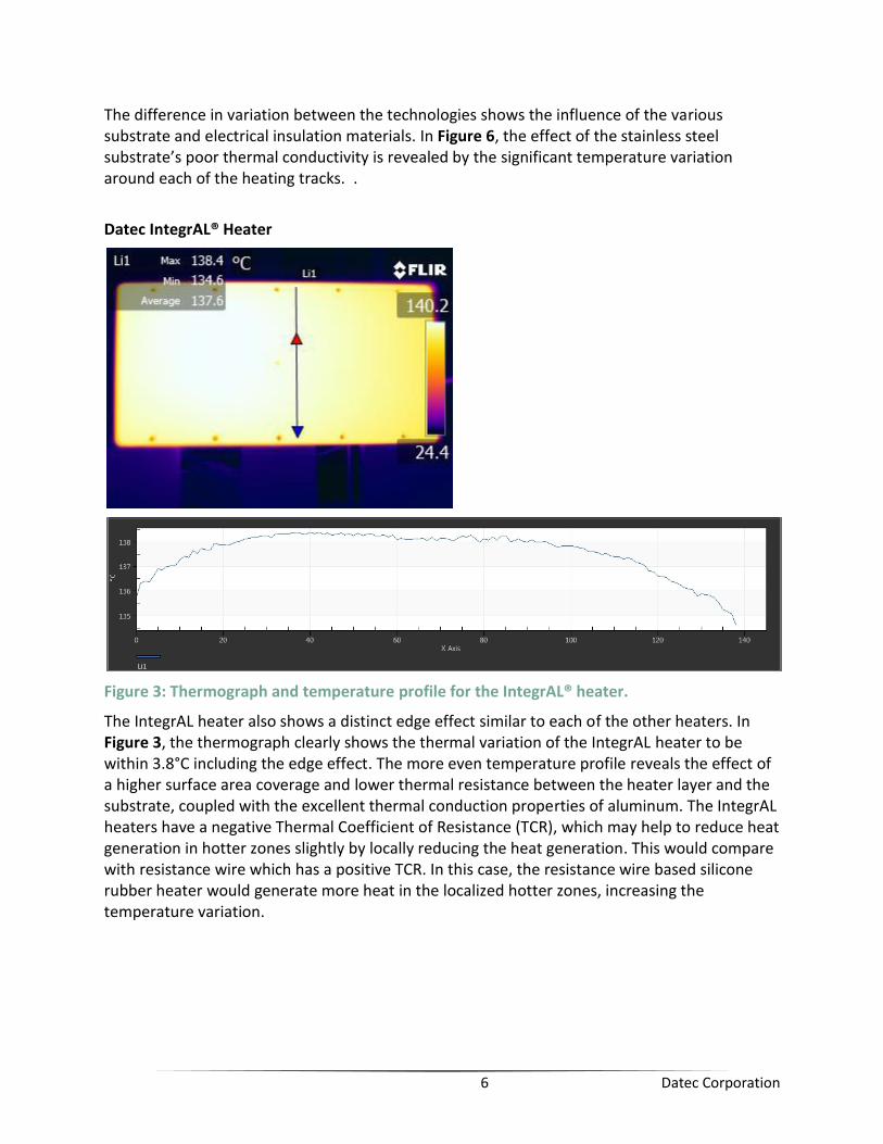
The temperature profile of the working side of each of the heated platens was analyzed using the IR camera. The temperature profiles shown in Figures 3, 4, 5 and 6 were recorded after heating the platens at rated power to approximately 140°C and then cycled 3 times from 120°C to approximately 140°C. The thermograph was recorded during the 4th heat up cycle. Under these conditions, the recorded temperature profile showed a temperature variation of 3.8°C for the IntegrAL heater, 12.4°C for the polyimide heater, 6.7°C for the silicone heater, and in excess of 45°C for the cermet heater.
0
20
40
60
80
100
120
140
160
0 500 1000 1500 2000 2500 3000 3500
Temperatu
re,˚C
Time, s
Cycling Rate Comparison for Heated Platen
Polyimide Insulated -Average
Silicone Rubber-Average
Datec IntegrAL® -Average
6 Datec Corporation
The difference in variation between the technologies shows the influence of the various substrate and electrical insulation materials. In Figure 6, the effect of the stainless steel substrate’s poor thermal conductivity is revealed by the significant temperature variation around each of the heating tracks. .
Datec IntegrAL® Heater
Figure 3: Thermograph and temperature profile for the IntegrAL® heater.
The IntegrAL heater also shows a distinct edge effect similar to each of the other heaters. In Figure 3, the thermograph clearly shows the thermal variation of the IntegrAL heater to be within 3.8°C including the edge effect. The more even temperature profile reveals the effect of a higher surface area coverage and lower thermal resistance between the heater layer and the substrate, coupled with the excellent thermal conduction properties of aluminum. The IntegrAL heaters have a negative Thermal Coefficient of Resistance (TCR), which may help to reduce heat generation in hotter zones slightly by locally reducing the heat generation. This would compare with resistance wire which has a positive TCR. In this case, the resistance wire based silicone rubber heater would generate more heat in the localized hotter zones, increasing the temperature variation.
7 Datec Corporation
Polyimide Heater
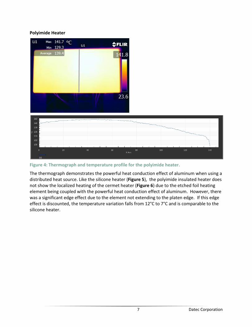
Figure 4: Thermograph and temperature profile for the polyimide heater.
The thermograph demonstrates the powerful heat conduction effect of aluminum when using a distributed heat source. Like the silicone heater (Figure 5), the polyimide insulated heater does not show the localized heating of the cermet heater (Figure 6) due to the etched foil heating element being coupled with the powerful heat conduction effect of aluminum. However, there was a significant edge effect due to the element not extending to the platen edge. If this edge effect is discounted, the temperature variation falls from 12°C to 7°C and is comparable to the silicone heater.
8 Datec Corporation
Silicone Heater
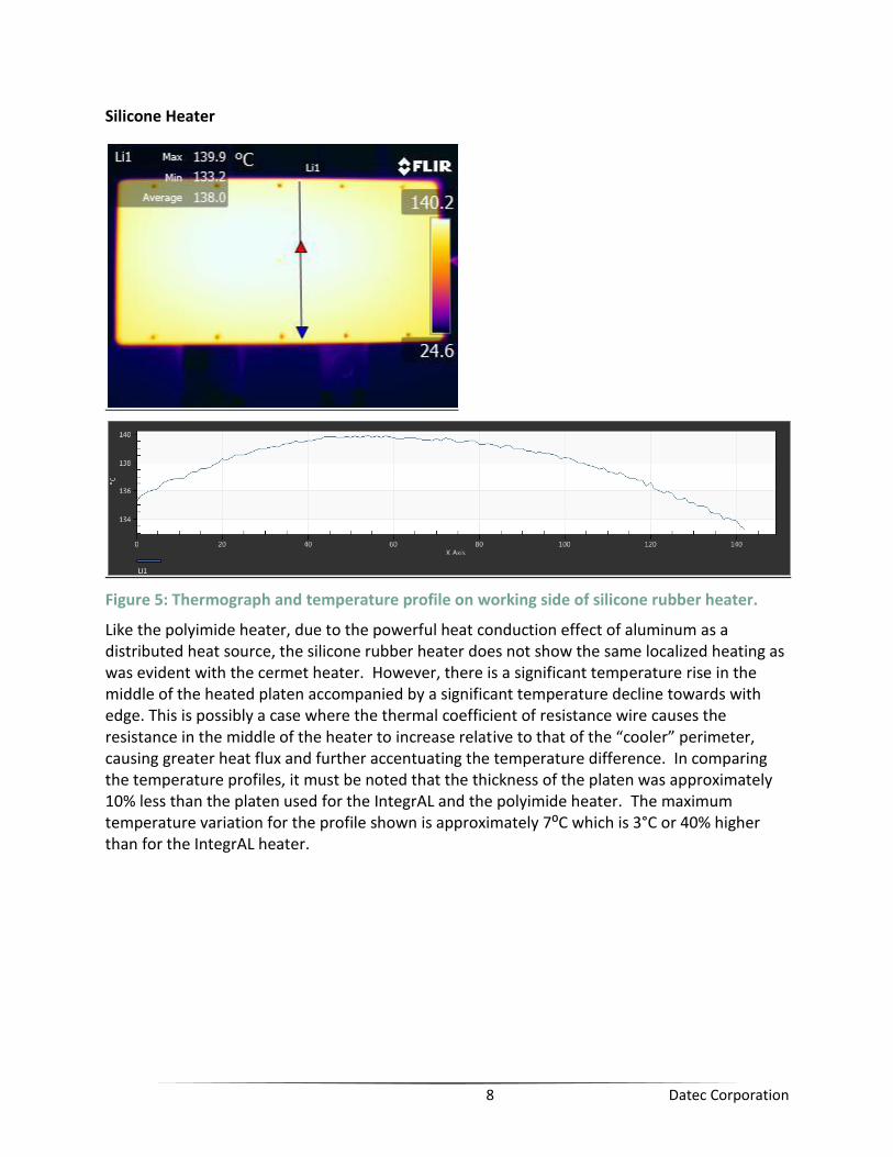
Figure 5: Thermograph and temperature profile on working side of silicone rubber heater.
Like the polyimide heater, due to the powerful heat conduction effect of aluminum as a distributed heat source, the silicone rubber heater does not show the same localized heating as was evident with the cermet heater. However, there is a significant temperature rise in the middle of the heated platen accompanied by a significant temperature decline towards with edge. This is possibly a case where the thermal coefficient of resistance wire causes the resistance in the middle of the heater to increase relative to that of the “cooler” perimeter, causing greater heat flux and further accentuating the temperature difference. In comparing the temperature profiles, it must be noted that the thickness of the platen was approximately 10% less than the platen used for the IntegrAL and the polyimide heater. The maximum temperature variation for the profile shown is approximately 7⁰C which is 3°C or 40% higher than for the IntegrAL heater.
9 Datec Corporation
Cermet Heater
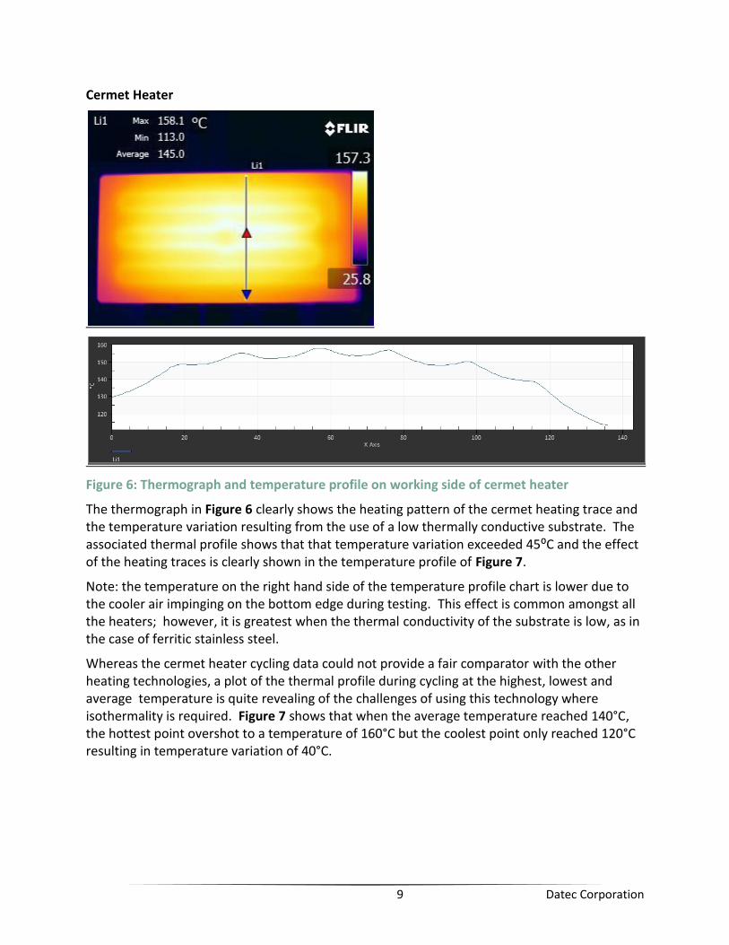
Figure 6: Thermograph and temperature profile on working side of cermet heater
The thermograph in Figure 6 clearly shows the heating pattern of the cermet heating trace and the temperature variation resulting from the use of a low thermally conductive substrate. The associated thermal profile shows that that temperature variation exceeded 45⁰C and the effect of the heating traces is clearly shown in the temperature profile of Figure 7.
Note: the temperature on the right hand side of the temperature profile chart is lower due to the cooler air impinging on the bottom edge during testing. This effect is common amongst all the heaters; however, it is greatest when the thermal conductivity of the substrate is low, as in the case of ferritic stainless steel.
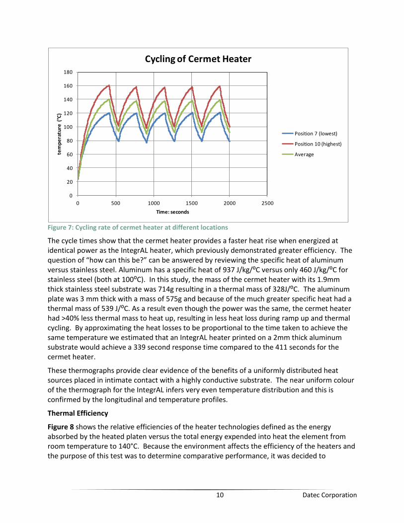
Whereas the cermet heater cycling data could not provide a fair comparator with the other heating technologies, a plot of the thermal profile during cycling at the highest, lowest and average temperature is quite revealing of the challenges of using this technology where isothermality is required. Figure 7 shows that when the average temperature reached 140°C, the hottest point overshot to a temperature of 160°C but the coolest point only reached 120°C resulting in temperature variation of 40°C.
10 Datec Corporation
Figure 7: Cycling rate of cermet heater at different locations
The cycle times show that the cermet heater provides a faster heat rise when energized at identical power as the IntegrAL heater, which previously demonstrated greater efficiency. The question of “how can this be?” can be answered by reviewing the specific heat of aluminum versus stainless steel. Aluminum has a specific heat of 937 J/kg/⁰C versus only 460 J/kg/⁰C for stainless steel (both at 100⁰C). In this study, the mass of the cermet heater with its 1.9mm thick stainless steel substrate was 714g resulting in a thermal mass of 328J/⁰C. The aluminum plate was 3 mm thick with a mass of 575g and because of the much greater specific heat had a thermal mass of 539 J/⁰C. As a result even though the power was the same, the cermet heater had >40% less thermal mass to heat up, resulting in less heat loss during ramp up and thermal cycling. By approximating the heat losses to be proportional to the time taken to achieve the same temperature we estimated that an IntegrAL heater printed on a 2mm thick aluminum substrate would achieve a 339 second response time compared to the 411 seconds for the cermet heater.
These thermographs provide clear evidence of the benefits of a uniformly distributed heat sources placed in intimate contact with a highly conductive substrate. The near uniform colour of the thermograph for the IntegrAL infers very even temperature distribution and this is confirmed by the longitudinal and temperature profiles.
Thermal Efficiency
Figure 8 shows the relative efficiencies of the heater technologies defined as the energy absorbed by the heated platen versus the total energy expended into heat the element from room temperature to 140°C. Because the environment affects the efficiency of the heaters and the purpose of this test was to determine comparative performance, it was decided to
0
20
40
60
80
100
120
140
160
180
0 500 1000 1500 2000 2500
tem
pe
ratu
re (
°C)
Time: seconds
Cycling of Cermet Heater
Position 7 (lowest)
Position 10 (highest)
Average
11 Datec Corporation
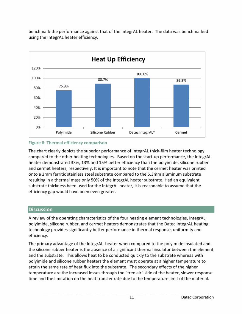
benchmark the performance against that of the IntegrAL heater. The data was benchmarked using the IntegrAL heater efficiency.
Figure 8: Thermal efficiency comparison The chart clearly depicts the superior performance of IntegrAL thick-film heater technology compared to the other heating technologies. Based on the start-up performance, the IntegrAL heater demonstrated 33%, 13% and 15% better efficiency than the polyimide, silicone rubber and cermet heaters, respectively. It is important to note that the cermet heater was printed onto a 2mm ferritic stainless steel substrate compared to the 5.3mm aluminum substrate resulting in a thermal mass only 50% of the IntegrAL heater substrate. Had an equivalent substrate thickness been used for the IntegrAL heater, it is reasonable to assume that the efficiency gap would have been even greater.
Discussion
A review of the operating characteristics of the four heating element technologies, IntegrAL, polyimide, silicone rubber, and cermet heaters demonstrates that the Datec IntegrAL heating technology provides significantly better performance in thermal response, uniformity and efficiency.
The primary advantage of the IntegrAL heater when compared to the polyimide insulated and the silicone rubber heater is the absence of a significant thermal insulator between the element and the substrate. This allows heat to be conducted quickly to the substrate whereas with polyimide and silicone rubber heaters the element must operate at a higher temperature to attain the same rate of heat flux into the substrate. The secondary effects of the higher temperature are the increased losses through the “free air” side of the heater, slower response time and the limitation on the heat transfer rate due to the temperature limit of the material.
75.3%
88.7%
100.0%
86.8%
0%
20%
40%
60%
80%
100%
120%
Polyimide Silicone Rubber Datec IntegrAL® Cermet
Heat Up Efficiency
12 Datec Corporation
The inherent higher area coverage of the IntegrAL resistor circuit, results in a greater distributed heat and a lower circuit temperature. As a result, when compared to cermet heaters, the IntegrAL heaters provide far better temperature uniformity and better energy efficiency. The poor thermal conductivity of the stainless steel substrate limited the heat transfer and efficiency of the cermet heater since the zones with higher temperature had disproportionately higher losses compared to the lower, more even heating temperature of the IntegrAL heater. If temperature uniformity was required, the cermet heater would be incapable of meeting this requirement due to the poor substrate thermal conductivity. This operating characteristic cannot be overcome by using aluminum since cermet processing temperatures exceed the melting temperature of aluminum. Even though the direct response time comparison between cermet and IntegrAL heater technology was biased by the lower thermal mass of the cermet heater, interpretation of the data predicts that under equivalent conditions, the IntegrAL heater would have a better response time.
Conclusion
The Datec IntegrAL® heating technology provides a superior performance in response time, uniformity and efficiency when compared to equivalent polyimide, silicone rubber and cermet heaters in an identical application. The faster response time provides faster cycling in applications where the cycling frequency is critical to performance. The ability to transfer more heat directly to the aluminum platen in a distributed manner and achieving better uniformity provides a higher degree of temperature control for applications where isothermality is important. The greater efficiency allows for reduced power requirements to achieve the same performance and reduced thermal management considerations for dealing with waste heat. Furthermore, the ability to transfer heat more efficiently infers the capability to achieve higher watt densities as compared to the other tested heating technologies.
Datec Corporation
130 Matheson Blvd E, Unit 2, Mississauga ON L4Z 1Y6 Canada
Tel: 905 629 3779 Email: [email protected] Web: www.dateccoating.com