Embed Size (px)
Citation preview
ThinSight: Versatile Multi-touch Sensing for Thin Form-factor Displays
Steve Hodges, Shahram Izadi, Alex Butler, Alban Rrustemi and Bill Buxton Microsoft Research Cambridge
7 JJ Thomson Avenue Cambridge, CB3 0FB
{shodges, shahrami, dab, v-albanr, bibuxton}@microsoft.com
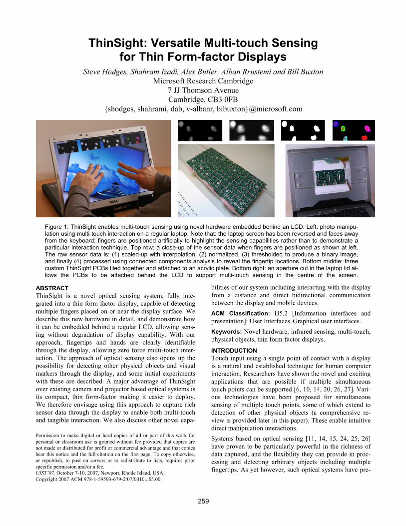
Figure 1: ThinSight enables multi-touch sensing using novel hardware embedded behind an LCD. Left: photo manipu-lation using multi-touch interaction on a regular laptop. Note that: the laptop screen has been reversed and faces away from the keyboard; fingers are positioned artificially to highlight the sensing capabilities rather than to demonstrate a particular interaction technique. Top row: a close-up of the sensor data when fingers are positioned as shown at left. The raw sensor data is: (1) scaled-up with interpolation, (2) normalized, (3) thresholded to produce a binary image, and finally (4) processed using connected components analysis to reveal the fingertip locations. Bottom middle: three custom ThinSight PCBs tiled together and attached to an acrylic plate. Bottom right: an aperture cut in the laptop lid al-lows the PCBs to be attached behind the LCD to support multi-touch sensing in the centre of the screen.
ABSTRACT ThinSight is a novel optical sensing system, fully inte-grated into a thin form factor display, capable of detecting multiple fingers placed on or near the display surface. We describe this new hardware in detail, and demonstrate how it can be embedded behind a regular LCD, allowing sens-ing without degradation of display capability. With our approach, fingertips and hands are clearly identifiable through the display, allowing zero force multi-touch inter-action. The approach of optical sensing also opens up the possibility for detecting other physical objects and visual markers through the display, and some initial experiments with these are described. A major advantage of ThinSight over existing camera and projector based optical systems is its compact, thin form-factor making it easier to deploy. We therefore envisage using this approach to capture rich sensor data through the display to enable both multi-touch and tangible interaction. We also discuss other novel capa-
bilities of our system including interacting with the display from a distance and direct bidirectional communication between the display and mobile devices. ACM Classification: H5.2 [Information interfaces and presentation]: User Interfaces. Graphical user interfaces. Keywords: Novel hardware, infrared sensing, multi-touch, physical objects, thin form-factor displays.
INTRODUCTION Touch input using a single point of contact with a display is a natural and established technique for human computer interaction. Researchers have shown the novel and exciting applications that are possible if multiple simultaneous touch points can be supported [6, 10, 14, 20, 26, 27]. Vari-ous technologies have been proposed for simultaneous sensing of multiple touch points, some of which extend to detection of other physical objects (a comprehensive re-view is provided later in this paper). These enable intuitive direct manipulation interactions. Systems based on optical sensing [11, 14, 15, 24, 25, 26] have proven to be particularly powerful in the richness of data captured, and the flexibility they can provide in proc-essing and detecting arbitrary objects including multiple fingertips. As yet however, such optical systems have pre-
Permission to make digital or hard copies of all or part of this work for personal or classroom use is granted without fee provided that copies are not made or distributed for profit or commercial advantage and that copies bear this notice and the full citation on the first page. To copy otherwise, or republish, to post on servers or to redistribute to lists, requires prior specific permission and/or a fee. UIST’07, October 7-10, 2007, Newport, Rhode Island, USA. Copyright 2007 ACM 978-1-59593-679-2/07/0010...$5.00.
259
dominately been based on cameras and projectors requiring a large optical path in front of or behind the display. ThinSight is a novel optical sensing system, fully inte-grated into a thin form-factor display such as a regular LCD, capable of detecting multiple fingertips placed on or near the display surface. The system is based upon custom hardware embedded behind an LCD, which uses infrared (IR) sensing to detect IR-reflective objects such as finger-tips near the surface, without loss of display capabilities. See Figure 1. In this paper we focus on fully describing this hardware and its assembly within an LCD. The aim is to make this underlying technology readily available to practi-tioners, rather than presenting the new multi-touch interac-tion techniques that we believe this approach enables. We also describe our experiences and experiments with ThinSight so far, showing the capabilities of the approach. Our current prototype has fairly low resolution sensing and covers only a portion of the display. However, even at this low resolution, fingertips and hands are clearly identifiable through the ThinSight display, allowing multi-touch appli-cations to be rapidly prototyped by applying simple image processing techniques to the data. Another compelling as-pect of our optical approach is the ability to sense outlines of IR-reflective objects through the display. With small improvements in resolution, we envisage using detection of such physical objects near the surface for tangible input. ThinSight also has other novel capabilities, which we dis-cuss: it supports interactions at a distance using IR pointing devices, and it enables IR-based communication through the display with other electronic devices. A major advantage of ThinSight over existing, projected optical systems is its compact, low profile form-factor mak-ing multi-touch and tangible interaction techniques more practical and deployable in real-world settings. We believe that ThinSight provides a glimpse of a future where new display technologies such as organic LEDs (OLEDs), will cheaply incorporate optical sensing pixels alongside RGB pixels in a similar manner, resulting in the widespread adoption of thin form-factor multi-touch sensitive displays.
RELATED WORK The area of multi-touch has gained much attention recently due to widely disseminated research conducted by Han et al. [6] and with the advent of the iPhone [1] and Microsoft Surface [17]. However, it is a field with over two decades of history [3]. Despite this sustained interest there has been an evident lack of off-the-shelf solutions for detecting mul-tiple fingers and/or objects on a display surface. Here, we summarise the relevant research in this area and describe the few commercially available systems.
Camera-based systems One approach to detecting the position of a user’s hands and fingers as they interact with a display is to use a video camera. Computer vision algorithms are then applied to the raw image data to calculate the position of the hands or fingertips relative to the display. An early example is Vid-eoPlace [11]. Images of the user’s whole arm are captured
and segmented from a plain background to create silhou-ettes which are rendered digitally and used to interact with a virtual world. VideoPlace does not detect when the user is actually making contact with the surface. The Digi-talDesk [24] segments an image of a pointing finger against a cluttered background. A microphone is used to detect a finger tapping the desk. The Visual Touchpad [14] uses a stereo camera to track fingertips. The disparity between the image pairs determines the height of fingers above the touchpad; a threshold is set to coarsely detect contact with the surface. PlayAnywhere [26] introduces a number of additional image processing techniques for front-projected vision-based systems, including a shadow-based touch de-tection algorithm, a novel visual bar code scheme, paper tracking, and an optical flow algorithm for bimanual inter-action. Camera-based systems such as those described above obvi-ously require direct line-of-sight to the objects being sensed which in some cases can restrict usage scenarios. Occlusion problems are mitigated in PlayAnywhere by mounting the camera off-axis. A natural progression is to mount the camera behind the display. HoloWall [15] uses IR illuminant and a camera equipped with an IR pass filter behind a diffusive projection panel to detect hands and other IR-reflective objects in front. The system can accu-rately determine the contact areas by simply thresholding the infrared image. TouchLight [25] uses rear-projection onto a holographic screen, which is also illuminated from behind with IR light. A number of multi-touch application scenarios are enabled including high-resolution imaging capabilities. Han [6] describes a straightforward yet power-ful technique for enabling high-resolution multi-touch sensing on rear-projected surfaces based on frustrated total internal reflection. Compelling multi-touch applications have been demonstrated using this technique. The Re-acTable [10] also uses rear-projection, IR illuminant and a rear mounted IR camera to monitor fingertips, this time in a horizontal tabletop form-factor. It also detects and identi-fies objects with IR-reflective markers on their surface. The rich data generated by camera-based systems provides extreme flexibility. However as Wilson suggests [26] this flexibility comes at a cost, including the computational demands of processing high resolution images, susceptibil-ity to adverse lighting conditions and problems of motion blur. However, perhaps more importantly, these systems require the camera to be placed at some distance from the display to capture the entire scene, limiting their portabil-ity, practicality and introducing a setup and calibration cost.
Opaque embedded sensing Despite the power of camera-based systems, the associated drawbacks outlined above have resulted in a number of parallel research efforts to develop a non-vision based multi-touch display. One approach is to embed a multi-touch sensor of some kind behind a surface that can have an image projected onto it. A natural technology for this is capacitive sensing, where the capacitive coupling to ground
260
introduced by a fingertip is detected, typically by monitor-ing the rate of leakage of charge away from conductive plates or wires mounted behind the display surface. Some manufacturers such as Logitech and Apple have en-hanced the standard laptop-style touch pad to detect certain gestures based on more than one point of touch. However, in these systems using more than two or three fingers typi-cally results in ambiguities in the sensed data, which con-strains the gestures they support and limits their size con-siderably. Lee et al. [12] used capacitive sensing with a number of discrete metal electrodes arranged in a matrix configuration to support multi-touch over a larger area. Westerman [23] describes a sophisticated capacitive multi-touch system which generates x-ray like images of a hand interacting with an opaque sensing surface, which could be projected onto. A derivative of this work was commercial-ised by Fingerworks and may be used in the iPhone. DiamondTouch [4] is composed of a grid of row and col-umn antennas which emit signals that capacitively couple with users when they touch the surface. Users are also ca-pacitively coupled to receivers through pads on their chairs. In this way the system can identify which antennas behind the display surface are being touched and by which user. A user touching the surface at two points can produce ambiguities however. The SmartSkin [20] system consists of a grid of capacitively coupled transmitting and receiving antennas. As a finger approaches an intersection point, this causes a drop in coupling which is measured to determine finger proximity. The system is capable of supporting mul-tiple points of contact by the same user and generating im-ages of contact regions of the hand. SmartSkin and Dia-mondTouch also support physical objects [10, 20], but can only identify an object when a user touches it. Tactex provide another interesting example of an opaque multi-touch sensor, which uses transducers to measure sur-face pressure at multiple touch points [21].
Transparent overlays The systems above share one major disadvantage: they all rely on front-projection for display. The displayed image will therefore be broken up by the user’s fingers, hands and arms, which can degrade the user experience. Also, a large throw distance is required for projection which limits portability. Furthermore, physical objects can only be detected in limited ways, if object detection is supported at all. One alternative approach to address some of the issues of display and portability is to use a transparent sensing overlay in conjunction with a self-contained (i.e. not projected) dis-play such as an LCD panel. DualTouch [16] uses an off-the-shelf transparent resistive touch overlay to detect the position of two fingers. Such overlays typically report the average position when two fingers are touching. Assuming that one finger makes contact first and does not subsequently move, the position of a second touch point can be calculated. The Lemur music controller from JazzMutant [9] uses a proprie-tary resistive overlay technology to track up to 20 touch points simultaneously. Each point of contact must apply an
operating force of greater than 20N in order to be detected. The Philips Entertaible [13] takes a different ‘overlay’ ap-proach to detect up to 30 touch points. IR emitters and detec-tors are placed on a bezel around the screen. Breaks in the IR beams detect fingers and objects.
The need for intrinsically integrated sensing This previous sections have presented a number of multi-touch display technologies. Camera-based systems produce very rich data but have a number of drawbacks. Opaque sensing systems can more accurately detect fingers and ob-jects, but by their nature rely on projection. Transparent overlays alleviate this projection requirement, but the fidelity of sensed data is further reduced. It is difficult, for example, to support sensing of fingertips, hands and objects. A potential solution which addresses all of these require-ments is a class of technologies that we refer to as ‘intrinsi-cally integrated’ sensing. The common approach behind these is to distribute sensing across the display surface, where the sensors are integrated with the display elements. Hudson [8] reports on a prototype 0.7” monochrome display where LED pixels double up as light sensors. By operating one pixel as a sensor whilst its neighbours are illuminated, it is possible to detect light reflected from a fingertip close to the display. Han has demonstrated a similar sensor using an off-the-shelf LED display component [7]. The main draw-backs are the use of visible illuminant during sensing and practicalities of using LED based displays. SensoLED uses a similar approach with visible light, but this time based on polymer LEDs and photodiodes. A 1” sensing polymer dis-play has been demonstrated [2]. Toshiba has reported a 2.8” LCD Input Display prototype which can detect the shadows resulting from fingertips on the display [22]. This uses photosensors and signal processing circuitry integrated directly onto the LCD glass substrate. A prototype 3.5” LCD has also been demonstrated with the ability to scan images placed on it. Toshiba report that they eventually hope to reach commercial levels of performance. They have also very recently alluded to a second mode of operation where light emitted from the display may be de-tected if nearby objects reflect it back, which allows the sys-tem to be used in low ambient light conditions. It is not clear from the press release if the illuminant is visible or not. The motivation for the work described in this paper was to build on the concept of intrinsically integrated sensing. We extend the work above using invisible (IR) illuminant to al-low simultaneous display and sensing, and use current LCD and IR technologies to make prototyping practical in the near term. Another important aspect is support for much larger thin touch-sensitive displays than is provided by intrinsically integrated solutions to date, thereby making multi-touch op-eration practical.
INTRODUCING THINSIGHT Imaging through an LCD using IR light A key element in the construction of ThinSight is a device known as a retro-reflective optosensor. This is a sensing element which contains two components: a light emitter
261
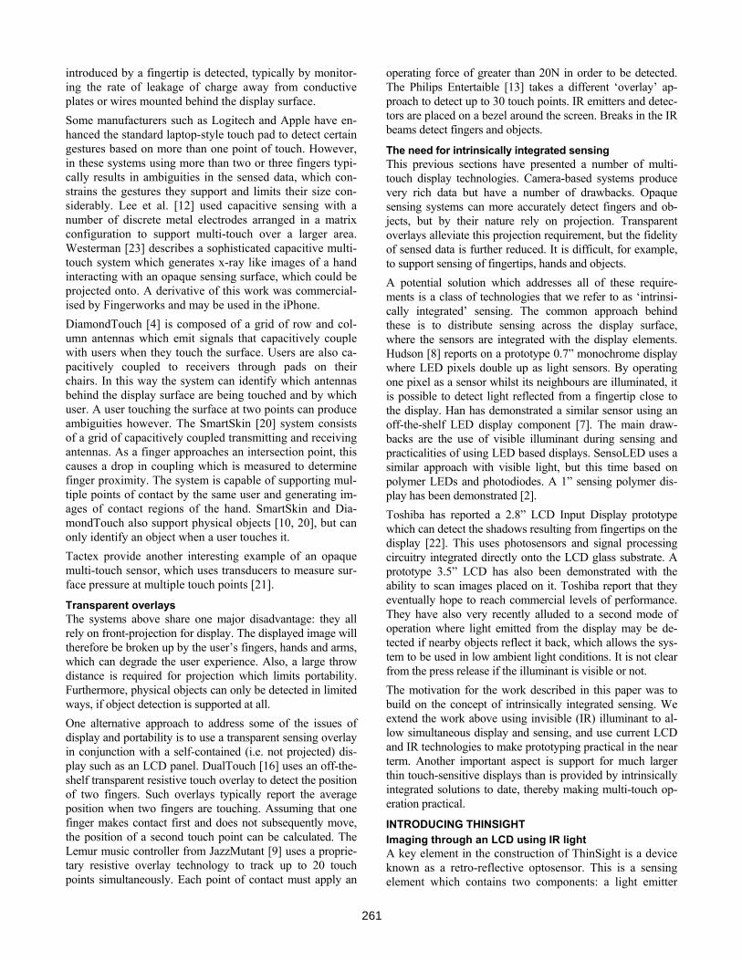
and an optically isolated light detector. It is therefore capa-ble of both emitting light and, at the same time, detecting the intensity of incident light. If a reflective object is placed in front of the optosensor, some of the emitted light will be reflected back and will therefore be detected. ThinSight is based around a 2D grid of retro-reflective op-tosensors which are placed behind an LCD panel. Each optosensor emits light that passes right through the entire panel. Any reflective object in front of the display (such as a fingertip) will reflect a fraction of the light back, and this can be detected. Figure 2 depicts this arrangement. By us-ing a suitable grid of retro-reflective optosensors distrib-uted uniformly behind the display it is therefore possible to detect any number of fingertips on the display surface. The raw data generated is essentially a low resolution greyscale “image” of what can be seen through the display in the infrared spectrum. By applying computer vision techniques to this image, it is possible to generate information about the number and position of multiple touch points.
Figure 2: The basic construction of ThinSight. An array of retro-reflective optosensors is placed be-hind an LCD. Each of these contains two elements: an emitter which shines IR light through the panel; and a detector which picks up any light reflected by objects such as fingertips in front of the screen.
A critical aspect of ThinSight is the use of retro-reflective sensors that operate in the infrared part of the spectrum, for a number of reasons: - Although IR light is attenuated by the layers in the
LCD panel, some still passes right through the display, as highlighted by [6]. This is unaffected by the dis-played image.
- A human fingertip typically reflects around 20% of incident IR light and is therefore a quite passable ‘re-flective object’.
- IR light is not visible to the user, and therefore doesn’t detract from the image being displayed on the panel.
In addition to operating ThinSight in a retro-reflective mode, it is also possible to disable the on-board IR emitters and use just the detectors. In this way, ThinSight can detect any ambient IR incident on the display. When there is rea-sonably strong ambient IR illumination, it is also possible to detect shadows cast on the touch panel such as those
resulting from fingertips and hands, by detecting the corre-sponding changes in incident IR. Although this mode of operation, which we call shadow mode, is not generally as reliable as the aforementioned reflective mode, it does have a number of very useful qualities which we discuss later.
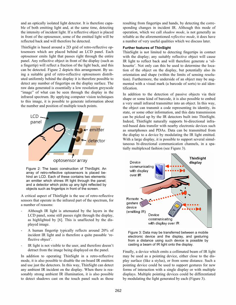
Further features of ThinSight ThinSight is not limited to detecting fingertips in contact with the display; any suitably reflective object will cause IR light to reflect back and will therefore generate a ‘sil-houette’. Not only can this be used to determine the loca-tion of the object on the display, but potentially also its orientation and shape (within the limits of sensing resolu-tion). Furthermore, the underside of an object may be aug-mented with a visual mark (a barcode of sorts) to aid iden-tification. In addition to the detection of passive objects via their shape or some kind of barcode, it is also possible to embed a very small infrared transmitter into an object. In this way, the object can transmit a code representing its identity, its state, or some other information, and this data transmission can be picked up by the IR detectors built into ThinSight. Indeed, ThinSight naturally supports bi-directional infra-red-based data transfer with nearby electronic devices such as smartphones and PDAs. Data can be transmitted from the display to a device by modulating the IR light emitted. With a large display, it is possible to support several simul-taneous bi-directional communication channels, in a spa-tially multiplexed fashion (see Figure 3).
Figure 3: Data may be transferred between a mobile electronic device and the display, and gesturing from a distance using such device is possible by casting a beam of IR light onto the display.
Finally, a device which emits a collimated beam of IR light may be used as a pointing device, either close to the dis-play surface (like a stylus), or from some distance. Such a pointing device could be used to support gestures for new forms of interaction with a single display or with multiple displays. Multiple pointing devices could be differentiated by modulating the light generated by each (Figure 3).
262
THINSIGHT HARDWARE IN MORE DETAIL LCD technology overview Before describing ThinSight in detail, it is useful to under-stand the construction and operation of a typical LCD panel. At the front of the panel is the LCD itself, which comprises a layer of liquid crystal material sandwiched between two polarisers. The polarisers are orthogonal to each other, which means that any light which passes through the first will naturally be blocked by the second, resulting in dark pixels. However, if a voltage is applied across the liquid crystal at a certain pixel location, the po-larisation of light incident on that pixel is twisted through 90° as it passes through the crystal structure. As a result it emerges from the crystal with the correct polarisation to pass through the second polariser. Typically, white light is shone through the panel from behind by a backlight and red, green and blue filters are used to create a colour dis-play. In order to achieve a low profile construction whilst maintaining uniform lighting across the entire display and keeping cost down, the backlight is often a large ‘light pipe’ in the form of a clear acrylic sheet which sits behind the entire LCD and which is edge-lit from one or more sides. The light source is often a cold cathode fluorescent tube or an array of white LEDs. To maximize the effi-ciency and uniformity of the lighting, additional layers of material may be placed between the backlight and the LCD. Brightness enhancing film ‘recycles’ visible light at sub-optimal angles and polarisations and a diffuser smoothes out any local non-uniformities in light intensity.
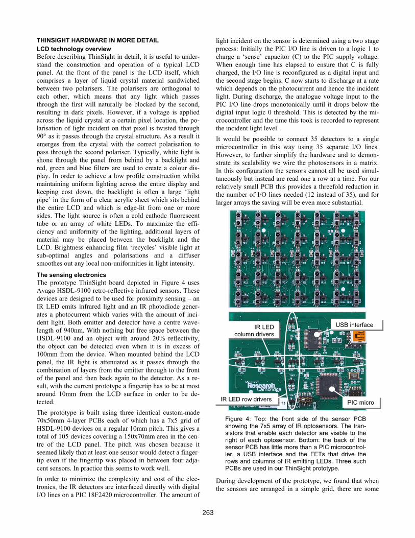
The sensing electronics The prototype ThinSight board depicted in Figure 4 uses Avago HSDL-9100 retro-reflective infrared sensors. These devices are designed to be used for proximity sensing – an IR LED emits infrared light and an IR photodiode gener-ates a photocurrent which varies with the amount of inci-dent light. Both emitter and detector have a centre wave-length of 940nm. With nothing but free space between the HSDL-9100 and an object with around 20% reflectivity, the object can be detected even when it is in excess of 100mm from the device. When mounted behind the LCD panel, the IR light is attenuated as it passes through the combination of layers from the emitter through to the front of the panel and then back again to the detector. As a re-sult, with the current prototype a fingertip has to be at most around 10mm from the LCD surface in order to be de-tected. The prototype is built using three identical custom-made 70x50mm 4-layer PCBs each of which has a 7x5 grid of HSDL-9100 devices on a regular 10mm pitch. This gives a total of 105 devices covering a 150x70mm area in the cen-tre of the LCD panel. The pitch was chosen because it seemed likely that at least one sensor would detect a finger-tip even if the fingertip was placed in between four adja-cent sensors. In practice this seems to work well. In order to minimize the complexity and cost of the elec-tronics, the IR detectors are interfaced directly with digital I/O lines on a PIC 18F2420 microcontroller. The amount of
light incident on the sensor is determined using a two stage process: Initially the PIC I/O line is driven to a logic 1 to charge a ‘sense’ capacitor (C) to the PIC supply voltage. When enough time has elapsed to ensure that C is fully charged, the I/O line is reconfigured as a digital input and the second stage begins. C now starts to discharge at a rate which depends on the photocurrent and hence the incident light. During discharge, the analogue voltage input to the PIC I/O line drops monotonically until it drops below the digital input logic 0 threshold. This is detected by the mi-crocontroller and the time this took is recorded to represent the incident light level. It would be possible to connect 35 detectors to a single microcontroller in this way using 35 separate I/O lines. However, to further simplify the hardware and to demon-strate its scalability we wire the photosensors in a matrix. In this configuration the sensors cannot all be used simul-taneously but instead are read one a row at a time. For our relatively small PCB this provides a threefold reduction in the number of I/O lines needed (12 instead of 35), and for larger arrays the saving will be even more substantial.
Figure 4: Top: the front side of the sensor PCB showing the 7x5 array of IR optosensors. The tran-sistors that enable each detector are visible to the right of each optosensor. Bottom: the back of the sensor PCB has little more than a PIC microcontrol-ler, a USB interface and the FETs that drive the rows and columns of IR emitting LEDs. Three such PCBs are used in our ThinSight prototype.
During development of the prototype, we found that when the sensors are arranged in a simple grid, there are some
IR LED row drivers
IR LEDcolumn drivers
PIC micro
USB interface
263
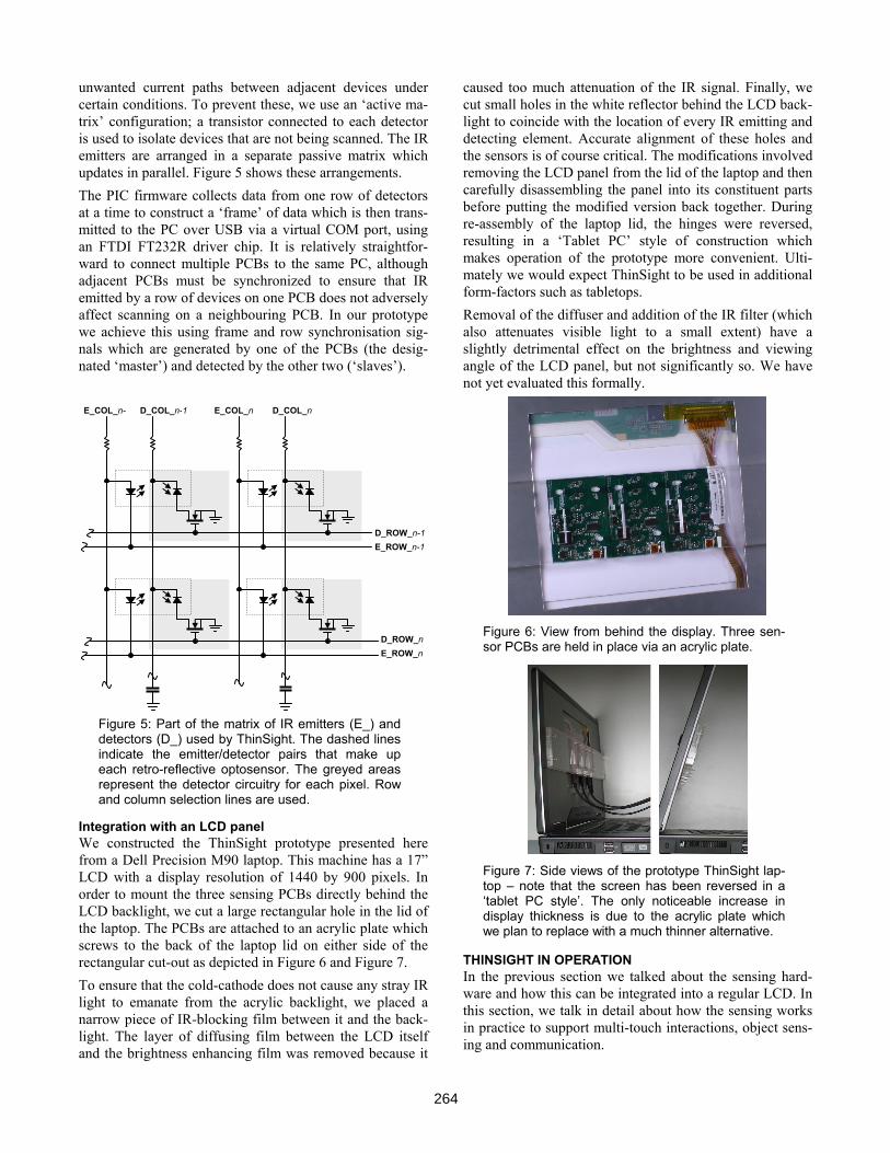
unwanted current paths between adjacent devices under certain conditions. To prevent these, we use an ‘active ma-trix’ configuration; a transistor connected to each detector is used to isolate devices that are not being scanned. The IR emitters are arranged in a separate passive matrix which updates in parallel. Figure 5 shows these arrangements. The PIC firmware collects data from one row of detectors at a time to construct a ‘frame’ of data which is then trans-mitted to the PC over USB via a virtual COM port, using an FTDI FT232R driver chip. It is relatively straightfor-ward to connect multiple PCBs to the same PC, although adjacent PCBs must be synchronized to ensure that IR emitted by a row of devices on one PCB does not adversely affect scanning on a neighbouring PCB. In our prototype we achieve this using frame and row synchronisation sig-nals which are generated by one of the PCBs (the desig-nated ‘master’) and detected by the other two (‘slaves’).
Figure 5: Part of the matrix of IR emitters (E_) and detectors (D_) used by ThinSight. The dashed lines indicate the emitter/detector pairs that make up each retro-reflective optosensor. The greyed areas represent the detector circuitry for each pixel. Row and column selection lines are used.
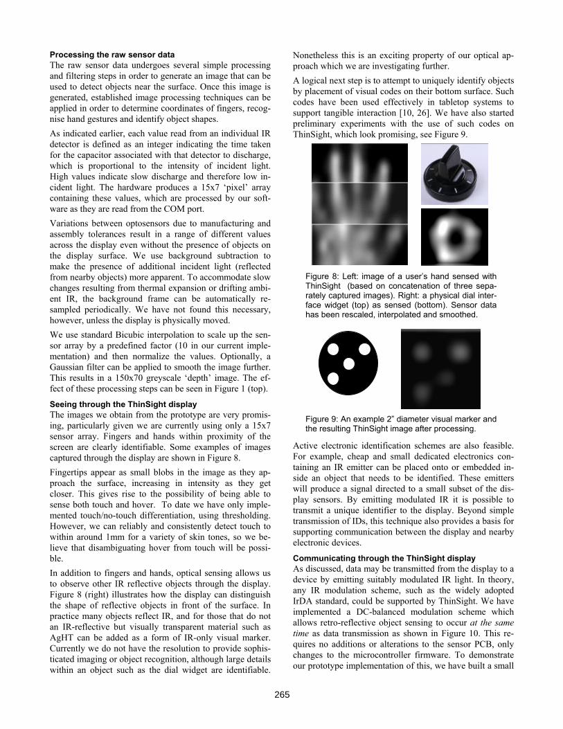
Integration with an LCD panel We constructed the ThinSight prototype presented here from a Dell Precision M90 laptop. This machine has a 17” LCD with a display resolution of 1440 by 900 pixels. In order to mount the three sensing PCBs directly behind the LCD backlight, we cut a large rectangular hole in the lid of the laptop. The PCBs are attached to an acrylic plate which screws to the back of the laptop lid on either side of the rectangular cut-out as depicted in Figure 6 and Figure 7. To ensure that the cold-cathode does not cause any stray IR light to emanate from the acrylic backlight, we placed a narrow piece of IR-blocking film between it and the back-light. The layer of diffusing film between the LCD itself and the brightness enhancing film was removed because it
caused too much attenuation of the IR signal. Finally, we cut small holes in the white reflector behind the LCD back-light to coincide with the location of every IR emitting and detecting element. Accurate alignment of these holes and the sensors is of course critical. The modifications involved removing the LCD panel from the lid of the laptop and then carefully disassembling the panel into its constituent parts before putting the modified version back together. During re-assembly of the laptop lid, the hinges were reversed, resulting in a ‘Tablet PC’ style of construction which makes operation of the prototype more convenient. Ulti-mately we would expect ThinSight to be used in additional form-factors such as tabletops. Removal of the diffuser and addition of the IR filter (which also attenuates visible light to a small extent) have a slightly detrimental effect on the brightness and viewing angle of the LCD panel, but not significantly so. We have not yet evaluated this formally.
Figure 6: View from behind the display. Three sen-sor PCBs are held in place via an acrylic plate.
Figure 7: Side views of the prototype ThinSight lap-top – note that the screen has been reversed in a ‘tablet PC style’. The only noticeable increase in display thickness is due to the acrylic plate which we plan to replace with a much thinner alternative.
THINSIGHT IN OPERATION In the previous section we talked about the sensing hard-ware and how this can be integrated into a regular LCD. In this section, we talk in detail about how the sensing works in practice to support multi-touch interactions, object sens-ing and communication.
E_COL_n D_COL_n
D_ROW_n-1 E_ROW_n-1
D_ROW_n E_ROW_n
E_COL_n- D_COL_n-1
264
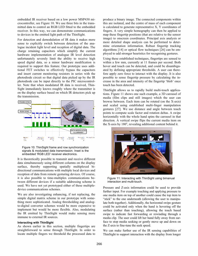
Processing the raw sensor data The raw sensor data undergoes several simple processing and filtering steps in order to generate an image that can be used to detect objects near the surface. Once this image is generated, established image processing techniques can be applied in order to determine coordinates of fingers, recog-nise hand gestures and identify object shapes. As indicated earlier, each value read from an individual IR detector is defined as an integer indicating the time taken for the capacitor associated with that detector to discharge, which is proportional to the intensity of incident light. High values indicate slow discharge and therefore low in-cident light. The hardware produces a 15x7 ‘pixel’ array containing these values, which are processed by our soft-ware as they are read from the COM port. Variations between optosensors due to manufacturing and assembly tolerances result in a range of different values across the display even without the presence of objects on the display surface. We use background subtraction to make the presence of additional incident light (reflected from nearby objects) more apparent. To accommodate slow changes resulting from thermal expansion or drifting ambi-ent IR, the background frame can be automatically re-sampled periodically. We have not found this necessary, however, unless the display is physically moved. We use standard Bicubic interpolation to scale up the sen-sor array by a predefined factor (10 in our current imple-mentation) and then normalize the values. Optionally, a Gaussian filter can be applied to smooth the image further. This results in a 150x70 greyscale ‘depth’ image. The ef-fect of these processing steps can be seen in Figure 1 (top).
Seeing through the ThinSight display The images we obtain from the prototype are very promis-ing, particularly given we are currently using only a 15x7 sensor array. Fingers and hands within proximity of the screen are clearly identifiable. Some examples of images captured through the display are shown in Figure 8. Fingertips appear as small blobs in the image as they ap-proach the surface, increasing in intensity as they get closer. This gives rise to the possibility of being able to sense both touch and hover. To date we have only imple-mented touch/no-touch differentiation, using thresholding. However, we can reliably and consistently detect touch to within around 1mm for a variety of skin tones, so we be-lieve that disambiguating hover from touch will be possi-ble. In addition to fingers and hands, optical sensing allows us to observe other IR reflective objects through the display. Figure 8 (right) illustrates how the display can distinguish the shape of reflective objects in front of the surface. In practice many objects reflect IR, and for those that do not an IR-reflective but visually transparent material such as AgHT can be added as a form of IR-only visual marker. Currently we do not have the resolution to provide sophis-ticated imaging or object recognition, although large details within an object such as the dial widget are identifiable.
Nonetheless this is an exciting property of our optical ap-proach which we are investigating further. A logical next step is to attempt to uniquely identify objects by placement of visual codes on their bottom surface. Such codes have been used effectively in tabletop systems to support tangible interaction [10, 26]. We have also started preliminary experiments with the use of such codes on ThinSight, which look promising, see Figure 9.
Figure 8: Left: image of a user’s hand sensed with ThinSight (based on concatenation of three sepa-rately captured images). Right: a physical dial inter-face widget (top) as sensed (bottom). Sensor data has been rescaled, interpolated and smoothed.
Figure 9: An example 2” diameter visual marker and the resulting ThinSight image after processing.
Active electronic identification schemes are also feasible. For example, cheap and small dedicated electronics con-taining an IR emitter can be placed onto or embedded in-side an object that needs to be identified. These emitters will produce a signal directed to a small subset of the dis-play sensors. By emitting modulated IR it is possible to transmit a unique identifier to the display. Beyond simple transmission of IDs, this technique also provides a basis for supporting communication between the display and nearby electronic devices.
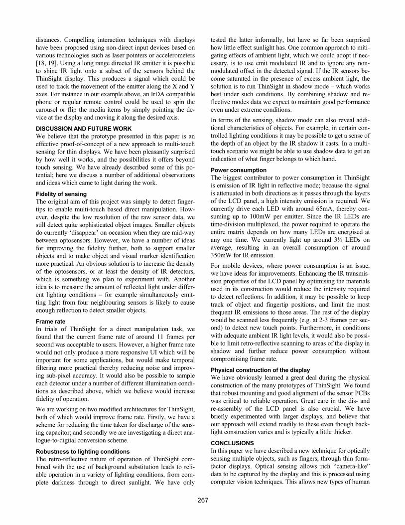
Communicating through the ThinSight display As discussed, data may be transmitted from the display to a device by emitting suitably modulated IR light. In theory, any IR modulation scheme, such as the widely adopted IrDA standard, could be supported by ThinSight. We have implemented a DC-balanced modulation scheme which allows retro-reflective object sensing to occur at the same time as data transmission as shown in Figure 10. This re-quires no additions or alterations to the sensor PCB, only changes to the microcontroller firmware. To demonstrate our prototype implementation of this, we have built a small
265
embedded IR receiver based on a low power MSP430 mi-crocontroller, see Figure 10. We use three bits in the trans-mitted data to control an RGB LED fitted to the embedded receiver. In this way, we can demonstrate communications to devices in the emitted light path of the ThinSight. For detection and demodulation of IR data it makes more sense to explicitly switch between detection of the ana-logue incident light level and reception of digital data. The charge retaining capacitors which simplify the current hardware implementation of analogue IR level detection unfortunately severely limit the ability to receive high speed digital data, so a minor hardware modification is required to support this feature. Our prototype uses addi-tional FET switches to effectively bypass the capacitors and insert current monitoring resistors in series with the photodiode circuit so that digital data picked up by the IR photodiode can be input directly to the PIC microcontrol-ler. Note that when modulated IR data is received, Thin-Sight immediately knows roughly where the transmitter is on the display surface based on which IR detectors pick up the transmission.
FRAME SYNC
ROW SYNC
DATA-MODULATEDILLUMINANT
Figure 10: ThinSight frame and row synchronization signals & modulated data transmission. Inset is the embedded ‘RGB LED’ receiver electronics.
It is theoretically possible to transmit and receive different data simultaneously using different columns on the display surface, thereby supporting spatially multiplexed bi-directional communications with multiple local devices and reception of data from remote gesturing devices. Of course, it is also possible to time-multiplex communications be-tween different devices if a suitable addressing scheme is used. We have not yet prototyped either of these multiple-device communications schemes. We are also investigating enhancing, if not replacing, the simple digital matrix scheme in our prototype with some-thing more sophisticated. Analog thresholding and analog-to-digital converter schemes would be more expensive to implement but would be more flexible. Also, modulating the IR emitted by ThinSight would make sensing more immune to external IR sources.
Interacting with ThinSight As shown earlier in this section, multiple fingertips are straightforward to sense through ThinSight. In order to locate multiple fingers we threshold the processed data to
produce a binary image. The connected components within this are isolated, and the centre of mass of each component is calculated to generate representative X, Y coordinates of fingers. A very simple homography can then be applied to map these fingertip positions (that are relative to the sensor image) to onscreen coordinates. Principal axis analysis or more detailed shape analysis can be performed to deter-mine orientation information. Robust fingertip tracking algorithms [14] or optical flow techniques [26] can be em-ployed to add stronger heuristics for recognising gestures. Using these established techniques, fingertips are sensed to within a few mm, currently at 11 frames per second. Both hover and touch can be detected, and could be disambigu-ated by defining appropriate thresholds. A user can there-fore apply zero force to interact with the display. It is also possible to sense fingertip pressure by calculating the in-crease in the area and intensity of the fingertip ‘blob’ once touch has been detected. ThinSight allows us to rapidly build multi-touch applica-tions. Figure 11 shows one such example, a 3D carousel of media (film clips and still images) which the user can browse between. Each item can be rotated (on the X-axis) and scaled using established multi-finger manipulation gestures [27]. We use distance and angle between touch points to compute scale factor and rotation deltas. A swipe horizontally with the whole hand spins the carousel in that direction. A vertical swipe flips the current media item on the X-axis by 180o, revealing additional content behind it.
Figure 11: Interacting with ThinSight using bimanual interaction and multi-touch.
Pressure and Z-axis information could be used to provide further input. For example touching and applying pressure to one media item on top of another could cause the top item to “stick” to the one underneath (allowing the user to manipu-late both together). Additionally, the horizontal swipe gesture could be activated only when the hand is hovering off the surface (rather than touching), allowing the touch based swipe to indicate fast forwarding or rewinding through a media clip. The user could lift her hand fully away from sur-face to stop media seeking or gently move up and down on the Z-axis to fine-tune the seek speed. We can make further use of the IR sensing capabilities of ThinSight to support interaction with the display from longer
266
distances. Compelling interaction techniques with displays have been proposed using non-direct input devices based on various technologies such as laser pointers or accelerometers [18, 19]. Using a long range directed IR emitter it is possible to shine IR light onto a subset of the sensors behind the ThinSight display. This produces a signal which could be used to track the movement of the emitter along the X and Y axes. For instance in our example above, an IrDA compatible phone or regular remote control could be used to spin the carousel or flip the media items by simply pointing the de-vice at the display and moving it along the desired axis.
DISCUSSION AND FUTURE WORK We believe that the prototype presented in this paper is an effective proof-of-concept of a new approach to multi-touch sensing for thin displays. We have been pleasantly surprised by how well it works, and the possibilities it offers beyond touch sensing. We have already described some of this po-tential; here we discuss a number of additional observations and ideas which came to light during the work.
Fidelity of sensing The original aim of this project was simply to detect finger-tips to enable multi-touch based direct manipulation. How-ever, despite the low resolution of the raw sensor data, we still detect quite sophisticated object images. Smaller objects do currently ‘disappear’ on occasion when they are mid-way between optosensors. However, we have a number of ideas for improving the fidelity further, both to support smaller objects and to make object and visual marker identification more practical. An obvious solution is to increase the density of the optosensors, or at least the density of IR detectors, which is something we plan to experiment with. Another idea is to measure the amount of reflected light under differ-ent lighting conditions – for example simultaneously emit-ting light from four neighbouring sensors is likely to cause enough reflection to detect smaller objects.
Frame rate In trials of ThinSight for a direct manipulation task, we found that the current frame rate of around 11 frames per second was acceptable to users. However, a higher frame rate would not only produce a more responsive UI which will be important for some applications, but would make temporal filtering more practical thereby reducing noise and improv-ing sub-pixel accuracy. It would also be possible to sample each detector under a number of different illumination condi-tions as described above, which we believe would increase fidelity of operation. We are working on two modified architectures for ThinSight, both of which would improve frame rate. Firstly, we have a scheme for reducing the time taken for discharge of the sens-ing capacitor; and secondly we are investigating a direct ana-logue-to-digital conversion scheme.
Robustness to lighting conditions The retro-reflective nature of operation of ThinSight com-bined with the use of background substitution leads to reli-able operation in a variety of lighting conditions, from com-plete darkness through to direct sunlight. We have only
tested the latter informally, but have so far been surprised how little effect sunlight has. One common approach to miti-gating effects of ambient light, which we could adopt if nec-essary, is to use emit modulated IR and to ignore any non-modulated offset in the detected signal. If the IR sensors be-come saturated in the presence of excess ambient light, the solution is to run ThinSight in shadow mode – which works best under such conditions. By combining shadow and re-flective modes data we expect to maintain good performance even under extreme conditions. In terms of the sensing, shadow mode can also reveal addi-tional characteristics of objects. For example, in certain con-trolled lighting conditions it may be possible to get a sense of the depth of an object by the IR shadow it casts. In a multi-touch scenario we might be able to use shadow data to get an indication of what finger belongs to which hand.
Power consumption The biggest contributor to power consumption in ThinSight is emission of IR light in reflective mode; because the signal is attenuated in both directions as it passes through the layers of the LCD panel, a high intensity emission is required. We currently drive each LED with around 65mA, thereby con-suming up to 100mW per emitter. Since the IR LEDs are time-division multiplexed, the power required to operate the entire matrix depends on how many LEDs are energised at any one time. We currently light up around 3½ LEDs on average, resulting in an overall consumption of around 350mW for IR emission. For mobile devices, where power consumption is an issue, we have ideas for improvements. Enhancing the IR transmis-sion properties of the LCD panel by optimising the materials used in its construction would reduce the intensity required to detect reflections. In addition, it may be possible to keep track of object and fingertip positions, and limit the most frequent IR emissions to those areas. The rest of the display would be scanned less frequently (e.g. at 2-3 frames per sec-ond) to detect new touch points. Furthermore, in conditions with adequate ambient IR light levels, it would also be possi-ble to limit retro-reflective scanning to areas of the display in shadow and further reduce power consumption without compromising frame rate.
Physical construction of the display We have obviously learned a great deal during the physical construction of the many prototypes of ThinSight. We found that robust mounting and good alignment of the sensor PCBs was critical to reliable operation. Great care in the dis- and re-assembly of the LCD panel is also crucial. We have briefly experimented with larger displays, and believe that our approach will extend readily to these even though back-light construction varies and is typically a little thicker.
CONCLUSIONS In this paper we have described a new technique for optically sensing multiple objects, such as fingers, through thin form-factor displays. Optical sensing allows rich “camera-like” data to be captured by the display and this is processed using computer vision techniques. This allows new types of human
267
computer interfaces that exploit zero-force multi-touch and tangible interaction on thin form-factor displays such as those described in [27]. We have shown how this technique can be integrated with off-the-shelf LCD technology, making such interaction techniques more practical and deployable in real-world settings. We have many ideas for potential refinements to the Thin-Sight hardware, firmware and PC software which we plan to experiment with. We would obviously like to expand the sensing area to cover the entire display, which we believe will be relatively straightforward given the scalable nature of the hardware. We also want to move to larger size displays and experiment with more appealing form-factors such as tabletops. In addition to such incremental improvements, we also be-lieve that it will be possible to transition to an integrated ‘sensing and display’ solution which will be much more straightforward and cheaper to manufacture. An obvious approach is to incorporate optical sensors directly onto the LCD backplane, and as reported earlier early prototypes in this area are beginning to emerge [22]. Alternatively, poly-mer photodiodes may be combined on the same substrate as polymer OLEDs [2] for a similar result. Another approach, which we are currently exploring, is to operate some of the pixels in a regular OLED display as light sensors. Our initial experiments indicate this is possible (just as it is for regular LEDs [8]). The big advantage of this approach is that an ar-ray of sensing elements can be combined with a display at very little cost by simply replacing some of the visible pixels with ones that sense. This would essentially augment a dis-play with multi-touch input ‘for free’, enabling truly wide-spread adoption of this exciting technology.
ACKNOWLEDGMENTS We thank Stuart Taylor, Mike Molloy, Steve Bathiche, Andy Wilson and Turner Whitted for their invaluable input.
REFERENCES 1. Apple iPhone Multi-touch.
http://www.apple.com/iphone/technology/ 2. L. Bürgi et al., 2006. Optical proximity and touch sen-
sors based on monolithically integrated polymer photo-diodes and polymer LEDs. In Organic Electronics 7.
3. Bill Buxton, 2007. Multi-Touch Systems that I Have Known and Loved. http://www.billbuxton.com/multitouchOverview.html
4. Paul Dietz and Darren Leigh. DiamondTouch: a multi-user touch technology. In ACM UIST 2001.
5. P.H. Dietz et al. DT Controls: Adding Identity to Physi-cal Interfaces. In ACM UIST 2005.
6. J. Y. Han, 2005. Low-Cost Multi-Touch Sensing through Frustrated Total Internal Reflection. In ACM UIST 2005.
7. Jeff Han. Multi-Touch Sensing through LED Matrix Displays. http://cs.nyu.edu/~jhan/ledtouch/index.html
8. Scott Hudson, 2004. Using Light Emitting Diode Arrays as Touch-Sensitive Input and Output Devices. In ACM UIST 2004.
9. JazzMutant Lemur. http://www.jazzmutant.com/lemur_overview.php.
10. Sergi Jordà, Martin Kaltenbrunner, Günter Geiger, Ross Bencina, 2005. The reacTable. International Computer Music Conference (ICMC2005), 2005.
11. Myron W. Krueger, Thomas Gionfriddo, and Katrin Hinrichsen. Videoplace: an artificial reality. In ACM CHI 1985, 35--40.
12. S.K. Lee, W. Buxton, K.C. Smith, A Multi-Touch 3D Touch-Sensitive Tablet. In ACM CHI 1985.
13. Evert van Loenen et al. Entertaible: A Solution for So-cial Gaming Experiences. In Tangible Play workshop, IUI Conference, 2007.
14. Shahzad Malik and Joe Laszlo, 2004. Visual Touchpad: A Two-handed Gestural Input Device. In Conference on Multimodal Interfaces 2004.
15. Nobuyuki Matsushita and Jun Rekimoto, 1997. HoloWall: designing a finger, hand, body, and object sensitive wall. In ACM UIST 1997.
16. Nobuyuki Matsushita, Yuji Ayatsuka and Jun Rekimoto, 2000. Dual touch: a two-handed interface for pen-based PDAs. In ACM UIST 2000.
17. Microsoft Surface, http://www.surface.com 18. Nintendo Wii, http://www.wii.com 19. J. Dan R. Olsen and T. Nielsen. Laser pointer interac-
tion. In ACM CHI 2001, 17–22. 20. Rekimoto, J., SmartSkin: an infrastructure for freehand
manipulation on interactive surfaces. In ACM CHI 2002, 113-120.
21. Tactex Controls Inc. Array Sensors. http://www.tactex.com/products_array.php
22. Toshiba Matsushita, LCD with Finger Shadow Sensing, http://www3.toshiba.co.jp/tm_dsp/press/2005/05-09-29.htm
23. Wayne Westerman, 1999. Hand Tracking, Finger Identi-fication and Chordic Manipulation on a Multi-Touch Surface. PhD thesis, University of Delaware.
24. Pierre Wellner, 1993. Interacting with Paper on the Digital Desk. CACM 36(7): 86-96.
25. Andrew D. Wilson, 2004. TouchLight: An Imaging Touch Screen and Display for Gesture-Based Interac-tion. In Conference on Multimodal Interfaces 2004.
26. Andrew D. Wilson, 2005. PlayAnywhere: A Compact Interactive Tabletop Projection-Vision System. In ACM UIST 2005.
27. Mike Wu and Ravin Balakrishnan, 2003. Multi-finger and Whole Hand Gestural Interaction Techniques for Multi-User Tabletop Displays. In ACM UIST 2003.
268