Embed Size (px)
Citation preview
This content has been downloaded from IOPscience. Please scroll down to see the full text.
Download details:
IP Address: 144.217.70.220
This content was downloaded on 25/05/2018 at 04:42
Please note that terms and conditions apply.
Extreme-Temperature andHarsh-Environment Electronics
Physics, technology and applications

Extreme-Temperature andHarsh-Environment Electronics
Physics, technology and applications
Vinod Kumar KhannaCSIR-Central Electronics Engineering Research Institute Pilani-333031
(Rajasthan), India
IOP Publishing, Bristol, UK
ª IOP Publishing Ltd 2017
All rights reserved. No part of this publication may be reproduced, stored in a retrieval systemor transmitted in any form or by any means, electronic, mechanical, photocopying, recordingor otherwise, without the prior permission of the publisher, or as expressly permitted by law orunder terms agreed with the appropriate rights organization. Multiple copying is permitted inaccordance with the terms of licences issued by the Copyright Licensing Agency, the CopyrightClearance Centre and other reproduction rights organisations.
Permission to make use of IOP Publishing content other than as set out above may be soughtat [email protected].
Vinod Kumar Khanna has asserted his right to be identified as the author of this work inaccordance with sections 77 and 78 of the Copyright, Designs and Patents Act 1988.
ISBN 978-0-7503-1155-7 (ebook)ISBN 978-0-7503-1156-4 (print)ISBN 978-0-7503-1157-1 (mobi)
DOI 10.1088/978-0-7503-1155-7
Version: 20170301
IOP Expanding PhysicsISSN 2053-2563 (online)ISSN 2054-7315 (print)
British Library Cataloguing-in-Publication Data: A catalogue record for this book is availablefrom the British Library.
Published by IOP Publishing, wholly owned by The Institute of Physics, London
IOP Publishing, Temple Circus, Temple Way, Bristol, BS1 6HG, UK
US Office: IOP Publishing, Inc., 190 North Independence Mall West, Suite 601, Philadelphia,PA 19106, USA
Cover image: Computer illustration of NASA’s Juno spacecraft over Jupiter’s pole. Credit: MarkGarlick / Science Photo Library.

To my late father Shri Amarnath KhannaFor his earnest endeavours to shape my educational career.
To my beloved mother Smt. Pushpa KhannaFor her love and blessings to guide me on the path of Life.
To my daughter AlokaFor bringing joy and happiness in the family.
To my wife AmitaFor her unflinching and unfailing support.

Contents
Preface xxi
Acknowledgements xxiii
About this book xxiv
Author biography xxv
Abbreviations, acronyms, chemical symbols and mathematical notation xxvi
Roman alphabet symbols xxxii
Greek/other symbols xxxvi
1 Introduction and overview 1-1
1.1 Reasons for moving away from normal practices in electronics 1-1
1.2 Organization of the book 1-2
1.3 Temperature effects 1-2
1.3.1 Silicon-based electronics 1-2
1.3.2 Wide bandgap semiconductors 1-5
1.3.3 Passive components and packaging 1-6
1.3.4 Superconductivity 1-7
1.4 Harsh environment effects 1-7
1.4.1 Humidity and corrosion effects 1-7
1.4.2 Radiation effects 1-8
1.4.3 Vibration and mechanical shock effects 1-8
1.5 Discussion and conclusions 1-8
Review exercises 1-9
References 1-10
2 Operating electronics beyond conventional limits 2-1
2.1 Life-threatening temperature imbalances on Earth and other planets 2-1
2.2 Temperature disproportions for electronics 2-2
2.3 High-temperature electronics 2-2
2.3.1 The automotive industry 2-4
2.3.2 The aerospace industry 2-8
2.3.3 Space missions 2-12
2.3.4 Oil well logging equipment 2-14
2.3.5 Industrial and medical systems 2-16
2.4 Low-temperature electronics 2-16
vii
2.5 The scope of extreme-temperature and harsh-environment electronics 2-18
2.5.1 High-temperature operation: a serious vulnerability 2-19
2.5.2 Upgradation/degradation of performance by cooling 2-19
2.5.3 Corrosion: humidity and climatic effects 2-19
2.5.4 Deleterious effects of nuclear and electro-magnetic radiationson electronic systems
2-20
2.5.5 Vibration and shock effects 2-21
2.6 Discussion and conclusions 2-21
Review exercises 2-22
References 2-23
Part I Extreme-temperature electronics
3 Temperature effects on semiconductors 3-1
3.1 Introduction 3-1
3.2 The energy bandgap 3-1
3.3 Intrinsic carrier concentration 3-3
3.4 Carrier saturation velocity 3-7
3.5 Electrical conductivity of semiconductors 3-9
3.6 Free carrier concentration in semiconductors 3-10
3.7 Incomplete ionization and carrier freeze-out 3-10
3.8 Different ionization regimes 3-13
3.8.1 At temperatures T < 100 K: carrier freeze-out orincomplete ionization regime
3-13
3.8.2 At temperatures T ∼ 100 K, and within 100 K < T < 500 K:extrinsic or saturation regime
3-17
3.8.3 At temperatures T > 500 K: intrinsic regime 3-18
3.8.4 Proportionality to bandgap at T ⩾ 400 K 3-18
3.9 Mobilities of charge carriers in semiconductors 3-19
3.9.1 Scattering by lattice waves 3-20
3.9.2 Scattering by ionized impurities 3-20
3.9.3 Mobility in uncompensated and compensated semiconductors 3-20
3.9.4 Resultant mobility 3-22
3.10 Equations for mobility variation with temperature 3-23
3.10.1 Arora–Hauser–Roulston equation 3-23
3.10.2 Klaassen equations 3-24
3.10.3 MINIMOS mobility model 3-24
3.11 Mobility in MOSFET inversion layers at low temperatures 3-25
Extreme-Temperature and Harsh-Environment Electronics
viii
3.12 Carrier lifetime 3-26
3.13 Wider bandgap semiconductors than silicon 3-28
3.13.1 Gallium arsenide 3-28
3.13.2 Silicon carbide 3-28
3.13.3 Gallium nitride 3-29
3.13.4 Diamond 3-29
3.14 Discussion and conclusions 3-29
Review exercises 3-30
References 3-32
4 Temperature dependence of the electrical characteristics ofsilicon bipolar devices and circuits
4-1
4.1 Properties of silicon 4-1
4.2 Intrinsic temperature of silicon 4-2
4.3 Recapitulating single-crystal silicon wafer technology 4-5
4.3.1 Electronic grade polysilicon production 4-5
4.3.2 Single crystal growth 4-5
4.3.3 Photolithography 4-6
4.3.4 Thermal oxidation of silicon 4-6
4.3.5 n-type doping of silicon by thermal diffusion 4-8
4.3.6 p-type doping of silicon by thermal diffusion 4-8
4.3.7 Impurity doping by ion implantation 4-10
4.3.8 Low-pressure chemical vapor deposition 4-10
4.3.9 Plasma-enhanced chemical vapor deposition 4-11
4.3.10 Atomic layer deposition 4-12
4.3.11 Ohmic (non-rectifying) contacts to Si 4-12
4.3.12 Schottky contacts to Si 4-13
4.3.13 p–n junction and dielectric isolation in siliconintegrated circuits
4-13
4.4 Examining temperature effects on bipolar devices 4-16
4.4.1 The Shockley equation for the current–voltagecharacteristics of a p–n junction diode
4-16
4.4.2 Forward voltage drop across a p–n junction diode 4-19
4.4.3 Forward voltage of a Schottky diode 4-21
4.4.4 Reverse leakage current of a p–n junction diode 4-24
4.4.5 Avalanche breakdown voltage of a p–n junction diode 4-26
4.4.6 Analytical model of temperature coefficient of avalanchebreakdown voltage
4-30
Extreme-Temperature and Harsh-Environment Electronics
ix
4.4.7 Zener breakdown voltage of a diode 4-33
4.4.8 Storage time (ts) of a p+–n junction diode 4-33
4.4.9 Current gain of a bipolar junction transistor 4-34
4.4.10 Approximate analysis 4-39
4.4.11 Saturation voltage of a bipolar junction transistor 4-41
4.4.12 Reverse base and emitter currents of a bipolar junctiontransistor (ICBO and ICEO)
4-43
4.4.13 Dynamic response of a bipolar transistor 4-44
4.5 Bipolar analog circuits in the 25 °C to 300 °C range 4-45
4.6 Bipolar digital circuits in the 25 °C to 340 °C range 4-47
4.7 Discussion and conclusions 4-48
Review exercises 4-48
References 4-52
5 Temperature dependence of electrical characteristics of siliconMOS devices and circuits
5-1
5.1 Introduction 5-1
5.2 Threshold voltage of an n-channel enhancement mode MOSFET 5-3
5.3 On-resistance (RDS(ON)) of a double-diffused vertical MOSFET 5-7
5.4 Transconductance (gm) of a MOSFET 5-12
5.5 BVDSS and IDSS of a MOSFET 5-13
5.6 Zero temperature coefficient biasing point of MOSFET 5-13
5.7 Dynamic response of a MOSFET 5-16
5.8 MOS analog circuits in the 25 °C to 300 °C range 5-17
5.9 Digital CMOS circuits in −196 °C to 270 °C range 5-24
5.10 Discussion and conclusions 5-25
Review exercises 5-25
References 5-28
6 The influence of temperature on the performance ofsilicon–germanium heterojunction bipolar transistors
6-1
6.1 Introduction 6-1
6.2 HBT fabrication 6-3
6.3 Current gain and forward transit time of Si/Si1−xGex HBT 6-4
6.4 Comparison between Si BJT and Si/SiGe HBT 6-8
6.5 Discussion and conclusions 6-16
Review exercises 6-17
References 6-19
Extreme-Temperature and Harsh-Environment Electronics
x
7 The temperature-sustaining capability of gallium arsenideelectronics
7-1
7.1 Introduction 7-1
7.2 The intrinsic temperature of GaAs 7-4
7.3 Growth of single-crystal gallium arsenide 7-5
7.4 Doping of GaAs 7-6
7.5 Ohmic contacts to GaAs 7-7
7.5.1 Au–Ge/Ni/Ti contact to n-type GaAs for room-temperatureoperation
7-7
7.5.2 High-temperature ohmic contacts to n-type GaAs 7-8
7.6 Schottky contacts to GaAs 7-9
7.7 Commercial GaAs device evaluation in the 25 °C to 400 °Ctemperature range
7-9
7.8 Structural innovations for restricting the leakage current of GaAsMESFET up to 300 °C
7-11
7.9 Won et al threshold voltage model for a GaAs MESFET 7-12
7.10 The high-temperature electronic technique for enhancing theperformance of MESFETs up to 300 °C
7-15
7.11 The operation of GaAs complementary heterojunction FETsfrom 25 °C to 500 °C
7-16
7.12 GaAs bipolar transistor operation up to 400 °C 7-17
7.13 A GaAs-based HBT for applications up to 350 °C 7-17
7.14 AlxGaAs1−x/GaAs HBT 7-18
7.15 Discussion and conclusions 7-21
Review exercises 7-21
References 7-23
8 Silicon carbide electronics for hot environments 8-1
8.1 Introduction 8-1
8.2 Intrinsic temperature of silicon carbide 8-2
8.3 Silicon carbide single-crystal growth 8-6
8.4 Doping of silicon carbide 8-7
8.5 Surface oxidation of silicon dioxide 8-8
8.6 Schottky and ohmic contacts to silicon carbide 8-8
8.7 SiC p–n diodes 8-8
8.7.1 SiC diode testing up to 498 K 8-8
8.7.2 SiC diode testing up to 873 K 8-9
8.7.3 Operation of SiC integrated bridge rectifier up to 773 K 8-10
Extreme-Temperature and Harsh-Environment Electronics
xi
8.8 SiC Schottky-barrier diodes 8-10
8.8.1 Temperature effects on Si and SiC Schottky diodes 8-11
8.8.2 Schottky diode testing up to 623 K 8-11
8.8.3 Schottky diode testing up to 523 K 8-12
8.9 SiC JFETs 8-12
8.9.1 Characterization of SiC JFETs from 25 °C to 450 °C 8-14
8.9.2 500 °C operational test of 6H-SiC JFETs and ICs 8-15
8.9.3 6H-SiC JFET-based logic circuits for the 25 °C to 550 °C range 8-16
8.9.4 Long operational lifetime (10 000 h), 500 °C, 6H-SiC analogand digital ICs
8-18
8.9.5 Characterization of 6H-SiC JFETs and differential amplifiersup to 450 °C
8-18
8.10 SiC bipolar junction transistors 8-20
8.10.1 Characterization of SiC BJTs from 140 K to 460 K 8-21
8.10.2 Performance assessment of SiC BJT from −86 °C to 550 °C 8-22
8.11 SiC MOSFETs 8-23
8.12 Discussion and conclusions 8-23
Review exercises 8-24
References 8-26
9 Gallium nitride electronics for very hot environments 9-1
9.1 Introduction 9-1
9.2 Intrinsic temperature of gallium nitride 9-2
9.3 Growth of the GaN epitaxial layer 9-5
9.4 Doping of GaN 9-5
9.5 Ohmic contacts to GaN 9-6
9.5.1 Ohmic contacts to n-type GaN 9-6
9.5.2 Ohmic contacts to p-type GaN 9-7
9.6 Schottky contacts to GaN 9-7
9.7 GaN MESFET model with hyperbolic tangent function 9-7
9.8 AlGaN/GaN HEMTs 9-12
9.8.1 Operation of AlGaN/GaN HEMTs on 4H-SiC/sapphiresubstrates from 25 °C to 500 °C
9-12
9.8.2 Life testing of AlGaN/GaN HEMTs from 150 °C to 240 °C 9-14
9.8.3 Power characteristics of AlGaN/GaN HEMTs up to 368 °C 9-14
9.8.4 Mechanisms of the failure of high-power AlGaN/GaN HEMTsat high temperatures
9-15
Extreme-Temperature and Harsh-Environment Electronics
xii
9.9 InAlN/GaN HEMTs 9-15
9.9.1 AlGaN/GaN versus InAlN/GaN HEMTs forhigh-temperature applications
9-15
9.9.2 InAlN/GaN HEMT behavior up to 1000 °C 9-15
9.9.3 Thermal stability of barrier layer in InAlN/GaN HEMTs upto 1000 °C
9-16
9.9.4 Feasibility demonstration of HEMT operation at gigahertzfrequency up to 1000 °C
9-16
9.10 Discussion and conclusions 9-18
Review exercises 9-18
References 9-20
10 Diamond electronics for ultra-hot environments 10-1
10.1 Introduction 10-1
10.2 Intrinsic temperature of diamond 10-2
10.3 Synthesis of diamond 10-5
10.4 Doping of diamond 10-7
10.4.1 n-type doping 10-7
10.4.2 p-type doping 10-7
10.4.3 p-doping by hydrogenation termination of the diamond surface 10-8
10.5 A diamond p–n junction diode 10-9
10.6 Diamond Schottky diode 10-9
10.6.1 Diamond Schottky diode operation up to 1000 °C 10-9
10.6.2 Long-term operation of diamond Schottky barrier diodesup to 400 °C
10-12
10.7 Diamond BJT operating at <200 °C 10-12
10.8 Diamond MESFET 10-13
10.8.1 Hydrogen-terminated diamond MESFETs 10-13
10.8.2 Electrical characteristics of diamond MESFETs in20 °C to 100 °C temperature range
10-15
10.8.3 Hydrogen-terminated diamond MESFETs with apassivation layer
10-15
10.8.4 Operation of pulse or delta boron-doped diamondMESFETs up to 350 °C
10-16
10.8.5 Alternative approach to boron δ-doping profile 10-17
10.9 Diamond JFET 10-17
10.9.1 Operation of diamond JFETs with lateral p–n junctionsup to 723 K
10-17
Extreme-Temperature and Harsh-Environment Electronics
xiii
10.10 Diamond MISFET 10-20
10.11 Discussion and conclusions 10-22
Review exercises 10-22
References 10-24
11 High-temperature passive components, interconnectionsand packaging
11-1
11.1 Introduction 11-1
11.2 High-temperature resistors 11-1
11.2.1 Metal foil resistors 11-1
11.2.2 Wirewound resistors 11-3
11.2.3 Thin-film resistors 11-3
11.2.4 Thick-film resistors 11-3
11.3 High-temperature capacitors 11-4
11.3.1 Ceramic capacitors 11-4
11.3.2 Solid and wet tantalum capacitors 11-5
11.3.3 Teflon capacitors 11-8
11.4 High-temperature magnetic cores and inductors 11-8
11.4.1 Magnetic cores 11-8
11.4.2 Inductors 11-8
11.5 High-temperature metallization 11-10
11.5.1 Tungsten metallization on silicon 11-11
11.5.2 Tungsten: nickel metallization on nitrogen-dopedhomoepitaxial layers on p-type 4H- and 6H-SiC substrates
11-11
11.5.3 Nickel metallization on n-type 4H-SiC and Ni/Ti/Almetallization on p-type 4H-SiC
11-11
11.5.4 A thick-film Au interconnection system on alumina andaluminum nitride ceramic substrates
11-11
11.6 High-temperature packaging 11-12
11.6.1 Substrates 11-12
11.6.2 Die-attach materials 11-12
11.6.3 Wire bonding 11-13
11.6.4 Hermetic packaging 11-13
11.6.5 Joining the two parts of hermetic packages 11-15
11.7 Discussion and conclusions 11-15
Review exercises 11-15
References 11-17
Extreme-Temperature and Harsh-Environment Electronics
xiv
12 Superconductive electronics for ultra-cool environments 12-1
12.1 Introduction 12-1
12.2 Superconductivity basics 12-2
12.2.1 Low-temperature superconductors 12-2
12.2.2 Meissner effect 12-2
12.2.3 Critical magnetic field (HC) and critical currentdensity (JC)
12-5
12.2.4 Superconductor classification: type I and type II 12-5
12.2.5 The BCS theory of superconductivity 12-8
12.2.6 Ginzburg–Landau theory 12-10
12.2.7 London equations 12-13
12.2.8 Explanation of Meissner’s effect from London equations 12-14
12.2.9 Practical applications 12-16
12.2.10 High-temperature superconductor 12-17
12.3 Josephson junction 12-17
12.3.1 The DC Josephson effect 12-17
12.3.2 The AC Josephson effect 12-19
12.3.3 Theory 12-19
12.3.4 Gauge-invariant phase difference 12-24
12.4 Inverse AC Josephson effect: Shapiro steps 12-30
12.5 Superconducting quantum interference devices 12-33
12.5.1 DC SQUID 12-33
12.5.2 The AC or RF SQUID 12-37
12.6 Rapid single flux quantum logic 12-37
12.6.1 Difference from traditional logic 12-37
12.6.2 Generation of RFSQ voltage pulses 12-38
12.6.3 RFSQ building blocks 12-38
12.6.4 RFSQ reset–set flip-flop 12-38
12.6.5 RFSQ NOT gate or inverter 12-40
12.6.6 RFSQ OR gate 12-42
12.6.7 Advantages of RFSQ logic 12-43
12.6.8 Disadvantages of RFSQ logic 12-43
12.7 Discussion and conclusions 12-43
Review exercises 12-45
References 12-47
Extreme-Temperature and Harsh-Environment Electronics
xv
13 Superconductor-based microwave circuits operating atliquid-nitrogen temperatures
13-1
13.1 Introduction 13-1
13.2 Substrates for microwave circuits 13-2
13.3 HTS thin-film materials 13-3
13.3.1 Yttrium barium copper oxide 13-3
13.3.2 Thallium barium calcium copper oxide 13-3
13.4 Fabrication processes for HTS microwave circuits 13-3
13.5 Design and tuning approaches for HTS filters 13-3
13.6 Cryogenic packaging 13-7
13.7 HTS bandpass filters for mobile telecommunications 13-8
13.7.1 Filter design methodology 13-8
13.7.2 Filter fabrication and characterization 13-9
13.8 HTS JJ-based frequency down-converter 13-10
13.9 Discussion and conclusions 13-11
Review exercises 13-12
References 13-12
14 High-temperature superconductor-based power delivery 14-1
14.1 Introduction 14-1
14.2 Conventional electrical power transmission 14-2
14.2.1 Transmission materials 14-2
14.2.2 High-voltage transmission 14-2
14.2.3 Overhead versus underground power delivery 14-2
14.3 HTS wires 14-2
14.3.1 First generation (1G) HTS wire 14-3
14.3.2 Second generation (2G) HTS wire 14-4
14.4 HTS cable designs 14-6
14.4.1 Single-phase warm dielectric HTS cable 14-6
14.4.2 Single-phase cool dielectric HTS cable 14-6
14.4.3 Flow rate, pressure drop and HTS cable temperatures 14-8
14.4.4 Three-phase cold dielectric HTS cable 14-9
14.5 HTS fault current limiters 14-9
14.5.1 Resistive SFCL 14-9
14.5.2 Shielded-core SFCL 14-11
14.5.3 Saturable-core SFCL 14-12
Extreme-Temperature and Harsh-Environment Electronics
xvi
14.6 HTS transformers 14-12
14.7 Discussion and conclusions 14-13
Review exercises 14-14
References 14-15
Part II Harsh-environment electronics
15 Humidity and contamination effects on electronics 15-1
15.1 Introduction 15-1
15.2 Absolute and relative humidity 15-2
15.3 Relation between humidity, contamination and corrosion 15-2
15.4 Metals and alloys used in electronics 15-3
15.5 Humidity-triggered corrosion mechanisms 15-4
15.5.1 Electrochemical corrosion 15-4
15.5.2 Anodic corrosion 15-4
15.5.3 Galvanic corrosion 15-5
15.5.4 Cathodic corrosion 15-6
15.5.5 Creep corrosion 15-7
15.5.6 Stray current corrosion 15-9
15.5.7 The pop-corning effect 15-9
15.6 Discussion and conclusions 15-9
Review exercises 15-10
References 15-10
16 Moisture and waterproof electronics 16-1
16.1 Introduction 16-1
16.2 Corrosion prevention by design 16-1
16.2.1 The fault-tolerant design approach 16-1
16.2.2 Air–gas contact minimization 16-2
16.2.3 The tight dry encasing design 16-2
16.2.4 A judicious choice of materials for boundary surfaces 16-2
16.3 Parylene coatings 16-2
16.3.1 Parylene and its advantages 16-2
16.3.2 Types of parylene 16-3
16.3.3 The vapor deposition polymerization process forparylene coatings
16-3
16.3.4 Typical electrical properties 16-4
Extreme-Temperature and Harsh-Environment Electronics
xvii
16.3.5 Applications for corrosion prevention 16-4
16.4 Superhydrophobic coatings 16-5
16.4.1 Concept of superhydrophobicity 16-5
16.4.2 Standard deposition techniques versus plasma processes 16-5
16.4.3 The main technologies 16-7
16.4.4 Applications 16-7
16.5 Volatile corrosion inhibitor coatings 16-7
16.6 Silicones 16-8
16.7 Discussion and conclusions 16-10
Review exercises 16-10
References 16-11
17 Preventing chemical corrosion in electronics 17-1
17.1 Introduction 17-1
17.2 Sulfidic and oxidation corrosion from environmental gases 17-1
17.3 Electrolytic ion migration and galvanic coupling 17-2
17.4 Internal corrosion of integrated and printed circuit board circuits 17-2
17.5 Fretting corrosion 17-3
17.6 Tin whisker growth 17-4
17.7 Minimizing corrosion risks 17-4
17.7.1 Using non-corrosive chemicals in device application andassembly
17-4
17.7.2 Device protection with conformal coatings 17-5
17.8 Further protection methods 17-7
17.8.1 Potting or overmolding with a plastic 17-7
17.8.2 Porosity sealing or vacuum impregnation 17-8
17.9 Hermetic packaging 17-9
17.9.1 Multilayer ceramic packages 17-9
17.9.2 Pressed ceramic packages 17-10
17.9.3 Metal can packages 17-11
17.10 Hermetic glass passivation of discrete high-voltage diodes,transistors and thyristors
17-12
17.11 Discussion and conclusions 17-13
Review exercises 17-13
References 17-15
Extreme-Temperature and Harsh-Environment Electronics
xviii
18 Radiation effects on electronics 18-1
18.1 Introduction 18-1
18.2 Sources of radiation 18-2
18.2.1 Natural radiation sources 18-2
18.2.2 Man-made or artificial radiation sources 18-2
18.3 Types of radiation effects 18-4
18.3.1 Total ionizing dose (TID) effect 18-4
18.3.2 Single event effect 18-4
18.3.3 Dose-rate effect 18-4
18.4 Total dose effects 18-5
18.4.1 Gamma-ray effects 18-6
18.4.2 Neutron effects 18-7
18.5 Single event effects 18-9
18.5.1 Non-destructive SEEs 18-10
18.5.2 Destructive SSEs 18-11
18.6 Discussion and conclusions 18-12
Review exercises 18-13
References 18-14
19 Radiation-hardened electronics 19-1
19.1 The meaning of ‘radiation hardening’ 19-1
19.2 Radiation hardening by process (RHBP) 19-2
19.2.1 Reduction of space charge formation in silicon dioxide layers 19-2
19.2.2 Impurity profile tailoring and carrier lifetime control 19-2
19.2.3 Triple-well CMOS technology 19-2
19.2.4 Adoption of SOI technology 19-2
19.3 Radiation hardening by design 19-4
19.3.1 Edgeless or annular MOSFETs 19-4
19.3.2 Channel stoppers and guard rings 19-6
19.3.3 Controlling the charge dissipation by increasing thechannel width to the channel length ratio
19-6
19.3.4 Temporal filtering 19-9
19.3.5 Spatial redundancy 19-9
19.3.6 Temporal redundancy 19-10
19.3.7 Dual interlocked storage cell 19-11
19.4 Discussion and Conclusions 19-14
Review exercises 19-14
References 19-15
Extreme-Temperature and Harsh-Environment Electronics
xix
20 Vibration-tolerant electronics 20-1
20.1 Vibration is omnipresent 20-1
20.2 Random and sinusoidal vibrations 20-2
20.3 Countering vibration effects 20-2
20.4 Passive and active vibration isolators 20-3
20.5 Theory of passive vibration isolation 20-3
20.5.1 Case I: free undamped vibrations 20-4
20.5.2 Case II: forced undamped vibrations 20-6
20.5.3 Case III: forced vibrations with viscous damping 20-10
20.6 Mechanical spring vibration isolators 20-15
20.7 Air-spring vibration isolators 20-15
20.8 Wire-rope isolators 20-15
20.9 Elastomeric isolators 20-15
20.10 Negative stiffness isolators 20-15
20.11 Active vibration isolators 20-18
20.11.1 Working 20-18
20.11.2 Advantages 20-19
20.11.3 Applications 20-20
20.12 Discussion and conclusions 20-20
Review exercises 20-20
References 20-21
Extreme-Temperature and Harsh-Environment Electronics
xx
Preface
Customarily electronic devices and circuits are required to operate at roomtemperature. This is more a matter of convenience and convention than optimiza-tion. On lowering the temperature, the performance of electronic devices isimproved two-fold or by several orders of magnitude. This upgradation is observedin various forms, e.g. increased speed of digital systems, a better signal-to-noise ratioand greater bandwidth for analog systems, improved sensitivity for sensors, greaterprecision and range for measuring instruments, and overall deceleration of theageing process of materials. However, low temperature is not always beneficial, e.g.the current gain and breakdown voltage of bipolar transistors are degraded withdecreasing temperature. Broadly speaking, low-temperature electronics (LTE) hastwo offshoots: semiconductor-based electronics and superconductor-based elec-tronics. Semiconductor-based electronics pertains to electronics that can be madeto operate at any temperature from room temperature, or even much higher, downto the lowest cryogenic temperatures, 1 K or below. On the other hand, present-daysystems based on superconductivity are confined to operation at low cryogenictemperatures, below about 10 K, which has been a serious impediment to theirwidespread use. The advent of high-temperature superconductors and associatedsystems appears to hold some promise.
The other side of the story is high-temperature electronics (HTE). ‘High temper-ature’ is any temperature above 125 °C. This cut-off point is frequently specified asthe upper limit at which standard commercial silicon devices are supposed tofunction properly. However, tests on standard commercial components indicate thateven temperatures up to 150 °C may be applied to selected silicon components.Certain niche applications have to operate beyond the melting point of manymaterials used in present-day industrial electronics. Examples are monitors anddown-hole well-drilling tools for energy exploration. Aircraft and turbine enginecontrols also have to withstand high temperatures.
The scope of extreme temperature electronics (ETE) encompasses operation intemperature ranges outside the traditional commercial, industrial or military ranges,i.e. −55 °C/−65 °C to +125 °C. There are three categories of ETE, known as HTEreferring to temperatures over +125 °C, LTE for temperatures below −55 °C/−65 °C,and cryogenic temperature electronics, below −150 °C.
Apart from the extreme temperature applications discussed above, mention maybe made of chemically corrosive conditions. Excessively high humidity causescorrosion in electronic devices. Low humidity favors the building up of staticelectricity. Atmospheric corrosion, an electrochemical process that occurs on metalscovered by a thin film of water and ions, is often responsible for damage to electricaland electronic components leading to premature failures even in indoor ambientconditions.
Ionizing radiation consisting of electromagnetic waves such as x-rays and γ-rays,and particulate radiation, i.e. protons, electrons, neutrons, etc, causes malfunctionsand failures in electronic components and circuits. The extent of damage depends on
xxi
the type of radiation, its intensity or energy, the time of exposure and hence the dose,in addition to the distance between the radiation source and the electronicequipment.
Unconventional electronics is subdivided into different areas, e.g. electronicscapable of operating at high temperatures for deep well and geothermal logging,light weight ground and air vehicles, and space exploration; electronics benefittingfrom low-temperature operation as well as electronics able to withstand lowtemperatures for infrared systems, satellite communications and medical equipment,and newer opportunities in wireless and mobile communications, computers, andmeasurement and scientific equipment; electronics capable of countering thedetrimental effects of humid and chemically corrosive environments for use intropical climates and industries such as pulp and paper processing, oil and petroleumrefining, mining, foundry, chemicals, etc; and radiation environment electronics forthe space, medical and nuclear power industries.
This book has three objectives:(i) to explore the beneficial/harmful impacts of extreme temperatures on
electronic devices and circuits, as well as to enquire into the complexitiesintroduced by harsh conditions such as damp, dirty and radiation-filledenvironments;
(ii) to describe the techniques adopted to utilize the advantages of theseunconventional situations; and
(iii) to present the remedial measures taken to counteract and deal with theseunfavorable circumstances.
This book is written for graduate and research students in electrical and electronicengineering. It will serve as a useful supplement to microelectronics course material,treating this specialized discipline with breadth and depth. The book answers severalquestions that come to mind when one starts thinking and imagining beyond anormal electronics course. The book is also written to fulfill the needs of electronicdevice and process design engineers, as well as circuit and system developers engagedin this fast-moving field, covering both fundamentals and applications. Scientistsand professors engaged in this field will also find it useful as a comprehensive guideto the state-of-the-art electronic technologies for hostile environments.
Vinod Kumar KhannaCSIR-CEERI, Pilani
Extreme-Temperature and Harsh-Environment Electronics
xxii

Acknowledgements
Above all, I must thank Almighty God for giving me the vigor and wisdom tocomplete this work. I am grateful to all my colleagues and Director, CSIR-CEERI,Pilani for constant encouragement in my efforts. I wish to thank my editor andeditorial assistant for rejuvenating my interest and boosting my confidence fromtime to time. Their kind co-operation and support led to timely completion of thework. I owe a profound debt of gratitude to all authors/editors of research papers,magazine articles and web pages, on whose work this book is based. Most of theseexcellent works are cited in the bibliographies at the end of each chapter. However, ifanyone has inadvertently escaped mention, the same may be forgiven. Last but notleast, I am grateful to my family for providing the serene atmosphere and relievingme of many domestic responsibilities so that I could devote more time to bookwriting. To all the above, I express my sincere thanks.
Vinod Kumar KhannaCSIR-CEERI, Pilani
xxiii
About this book
Extreme-Temperature and Harsh-Environment Electronics: Physics, technology andapplications presents a unified perspective combining the impact of extremely highand exceedingly low temperatures on the operation of semiconductor electronics, inaddition to the influence of hostile environments such as high-humidity conditions,as well as surroundings contaminated by chemical vapors, nuclear radiations orthose disturbed by mechanical shocks and vibrations. Incorporating the preliminarybackground material and thus laying down foundations for easy understanding, theprogress in mainstream silicon, silicon-on-insulator and gallium arsenide electronicsis sketched. Contemporary wide bandgap semiconductor technologies such assilicon carbide, gallium nitride and diamond electronics are explored. After a brieftreatment of superconductivity, concepts of superconductive electronics are intro-duced. Progress in Josephson junctions, SQUIDs and RFSQ logic circuits ishighlighted. The state of the art in high-temperature superconductor-based powerdelivery is surveyed. Succeeding chapters look at various protection schemes thathave been devised to shield electronic circuits and equipment from adverse ambientconditions. These conditions range from the presence of high moisture concen-trations in the atmosphere, to showers of high-energy particles such as the alphaparticles, protons and nuclei of heavy elements that flood the atmosphere from outerspace. A particularly attractive area is the dampening of vibration effects to protectelectronics from the quivering disturbances or jerks that are always present nearlarge machines or during accidental falls of electronic equipment.
In this book, a lucid description of this vast panorama of topics is reinforced byan elegant mathematical treatment. Broad in scope, this comprehensive treatiseprovides a coherent, well-organized and amply illustrated exposition of the subjectwhich will be immensely useful for graduate and research students, professionalengineers and researchers engaged in this frontier of technology. Its three-prongedapproach encompassing physical aspects, technological breakthroughs and applica-tion examples will make reading interesting and enjoyable.
xxiv
Author biography
Vinod Kumar Khanna
Vinod Kumar Khanna, born on 25 November 1952 in Lucknow,Uttar Pradesh, India, is an Emeritus Scientist at the CSIR-CentralElectronics Engineering Research Institute, Pilani, Rajasthan,India, and Emeritus Professor, AcSIR (Academy of Scientific andInnovative Research), India. He is former Chief Scientist and Headof the MEMS and Microsensors Group, CSIR-CEERI, Pilani,and Professor, AcSIR. During his service tenure of more than
34 years at CSIR-CEERI, starting in April 1980, he has worked on various researchand development projects on power semiconductor devices (high-current andhigh-voltage rectifiers, high-voltage TV deflection transistors, power Darlingtontransistors, fast switching thyristors, power DMOSFETs and IGBTs), PIN diodeneutron dosimeters and PMOSFET gamma ray dosimeters, ion-sensitive field-effecttransistors (ISFETs), microheater-embedded gas sensors, capacitive MEMSultrasonic transducers (CMUTs) and other MEMS devices. His research interestshave covered micro- and nanosensors and power semiconductor devices. From 1977to 1979, he was a research assistant in the Physics Department, Lucknow University.
Dr Khanna’s deputations abroad include Technische Universität Darmstadt,Germany, 1999; Kurt-Schwabe-Institut für Mess- und Sensortechnik e.V.,Meinsberg, Germany, 2008; Institute of Chemical Physics, Novosibirsk, Russia,2009; and Fondazione Bruno Kessler, Povo, Trento, Italy, 2011. He also partici-pated in and presented research papers at the IEEE-IAS Annual Meeting, Denver,Colorado, USA, 1986.
Dr Khanna received his MSc degree in physics with specialization in electronicsfrom the University of Lucknow in 1975, and his PhD degree in physics fromKurukshetra University, Kurukshetra, Haryana, in 1988 for his work on a thin-filmaluminum oxide humidity sensor. A fellow of the Institution of Electronics andTelecommunication Engineers (IETE), India, he is a life member of the IndianPhysics Association (IPA), Semiconductor Society (India) (SSI), and Indo-FrenchTechnical Association.
Dr Khanna has published ten previous books, six chapters in edited books, and185 research papers in national/international journals and conference proceedings;he holds two US and two Indian patents.
xxv

Abbreviations, acronyms,chemical symbols andmathematical notation
A ampereAC alternating currentAg silver (argentum)Ag2O silver oxideAg2S silver sulfideAH absolute humidityAl aluminumALD atomic layer depositionAlGaAs aluminum gallium arsenideAlGaN aluminum gallium nitrideAlN aluminum nitrideAl2O3 aluminum oxideAs2O3 arsenic trioxideAs2O5 arsenic pentoxideAu gold (aurum)BaCO3 barium carbonateBCS Bardeen–Cooper–Schrieffer (theory of superconductivity)Be berylliumBGJFET buried-grid JFETB2H6 diboraneB2O3 boron trioxideBiCMOS bipolar CMOSBJT bipolar junction transistorBN boron nitrideBOX buried oxideBPF bandpass filterBSCCO bismuth–strontium–calcium–copper oxideBSG borosilicate glassC carbon°C degrees centigradeCeO2 cerium (IV) oxideCH4 methane(CH3)3B trimethyl boronCHFET complementary heterojunction FETC7H7N3 tolytriazoleC12H24N2O2 dicyclohexylammonium nitriteC6H8O7 citric acidC6H10O4 adipic acidCMOS complementary metal–oxide–semiconductor (FET)COB chip-on-board (assembly)
xxvi
CO-OP controlled over pressure (process)CoSi2 cobalt silicideCQT cascaded quadruplet trisection coupling structure (filter geometry)Cr chromiumCRT cathode ray tubeCTE coefficient of thermal expansionCVD chemical vapor depositionCu copperCuO copper oxideCu2S copper sulfideCZ Czochralski (single-crystal silicon)dB decibelDC direct currentDD displacement damageDI-BSCCO dynamically innovative-BSCCODICE dual interlocked storage cellDICHAN dicyclohexylammonium nitrite2DEG two-dimensional electron gas2DHG two-dimensional hole gasDGVTJFET dual-gate vertical channel trench JFETDMOSFET double-diffused MOSFETDMVTJFET depletion-mode VTJFETDRAM dynamic random access memorye-beam electron beamEG electronic grade (polysilicon)EHP electron hole pairEIA Electronics Industries AssociationEL Ni electroless nickelEMI electromagnetic interferenceEMVTJFET enhancement-mode VTJFETESD electrostatic dischargeETO ethylene oxideeV electron voltfcc face-centered cubicFCL fault current limiterFET field-effect transistorFIRST Far Infra-Red Space TelescopeGa galliumGaAs gallium arsenideGaN gallium nitrideGa2O3 gallium trioxideGe germaniumGHz gigahertzGTO gate turn-off (thyristor)Gy grayh hourHASL hot air solder levelingHBT heterojunction bipolar transistorHEMT high electron mobility transistorHFET heterojunction FET
Extreme-Temperature and Harsh-Environment Electronics
xxvii
HfO2 hafnium oxideHg mercury (hydrargyrum)HPHT high-pressure and high-temperatureHTE high-temperature electronicsHTS high-temperature superconductorHVAC high-voltage alternating currentHz hertzIBAD ion beam-assisted depositionIC integrated circuitIF intermediate frequencyi-GaN intrinsic gallium nitrideIGBT insulated gate bipolar transistorIM Au immersion goldInAlN indium aluminum nitrideInAs indium arsenideInGaAs indium gallium arsenideInP indium phosphideInSb indium antimonideISOPHOT Infrared Space Observatory PhotometerJFET junction FETJJ Josephson junctionJTE junction termination extensionK kelvin (scale of temperature)km kilometerkeV kilo-electronvoltkV kilovoltLaAlO3 lanthanum aluminateLaB6 lanthanum hexaborideLAO lanthanum aluminateLCD liquid crystal displayLCJFET lateral channel JFETLEC liquid encapsulated CzochralskiLED light-emitting diodeLi lithiumLO local oscillatorLPCVD low-pressure CVDLPF low-pass filterLTE low-temperature electronicsm metermA milli-ampereMAG maximum available gainMEA more electric aircraftMEMS microelectromechanical systemsMESFET metal–semiconductor FETmeV milli-electronvoltMg magnesiumMG metallurgical grade (polysilicon)MgO magnesium oxideMHz megahertzMISFET metal–insulator–semiconductor FET
Extreme-Temperature and Harsh-Environment Electronics
xxviii
mK millikelvinmm millimeterMMIC monolithic microwave ICMn(NO3)2 manganese nitrateMnO2 manganese dioxidemΩ milli-ohmMOCVD metal–organic CVDMOSFET metal–oxide–semiconductor FETMoSi2 molybdenum disilicideMPCVD microwave plasma-enhanced CVDMPS merged PiN/Schottky (diode)mS millisiemenMTTF mean-time-to-failureMV megavoltNaOH sodium hydroxideNb neobiumNi nickelNiCr nichromeNMOS n-channel MOSFETNP0 negative positive zeroNO2 nitrogen dioxide gasns nanosecondOCVD open circuit voltage decayOP-AMP operational amplifierOSP organic solderability preservativePb lead (plumbum)pBN pyrolytic boron nitridePCB printed circuit boardPCBA printed circuit board assemblyPECVD plasma-enhanced CVDPH3 phosphinePLD pulsed laser depositionPMOS p-channel MOSFETPOCl3 phosphorous oxychlorideps picosecondPSG phosphosilicate glassPt platinumPTFE polytetrafluoroethyleneQUAD quadruplerad radiation absorbed doseRAM random access memoryReBCO rare-earth barium copper oxideRF radio frequencyRFSQ rapid flux single quantumRH relative humidityRHBD radiation hardening by designRHBP radiation hardening by processRoHS restriction of hazardous substancesRPCVD reduced pressure CVDR–S reset-set (flip flop)
Extreme-Temperature and Harsh-Environment Electronics
xxix
R2SiO structural unit of silicone where R is an organic groupRTA rapid thermal annealingRTV room-temperature vulcanizationRu rutheniums secondS sulfur, siemenSBD Schottky barrier diodeSe seleniumSEB single event burnoutSEE single event effectSEFI single event functional interruptSEGR single event gate ruptureSEI Sumitomo Electric Industries LtdSEJFET static expansion channel JFETSEL single event latchupSES single event snapbackSET single event transientSEU single event upsetSFCL superconducting FCLSi siliconSIAFET static induction-injected accumulated FETSiC silicon carbideSiH4 silaneSiHCl3 trichlorosilaneSiH2Cl2 dichlorosilaneSiGe silicon–germanium (alloy)Si1−xGex silicon–germanium (alloy) where x is the mole fraction of germanium in
the alloy with a value from 0 to 1SMD surface mount deviceSi3N4 silicon nitrideSixOyNz silicon oxynitrideSiO2 silicon dioxideSi(OC2H5)4 tetraethylorthosilicate (TEOS)SISO spiral in/spiral out (resonator)Sn tin (stannum)SOI silicon-on-insulatorSQUID superconducting quantum interference deviceSRH Shockley–Read–Hall (recombination)SS subthreshold swingT teslaTaN tantalum nitrideTa2O5 tantalum pentoxideTaSi2 tantalum disilicideTBCCO thallium–barium–calcium–copper oxideTC temperature coefficientTCR TC of resistanceTCS trichlorosilaneTe telluriumTEOS tetraethylorthosilicateTID total ionizing dose
Extreme-Temperature and Harsh-Environment Electronics
xxx
Ti titaniumTiN titanium nitrideTiO2 titanium dioxideTiSi2 titanium disilicideTMB trimethylboronTMR triple modular redundancyTTL transistor–transistor logicUHVCVD ultra-high vacuum CVDUMOSFET U-shaped MOSFETUV ultravioletVCI volatile corrosion inhibitor (coating)V2O5 vanadium pentoxideVTJFET vertical trench JFETW tungsten, wattWb weberWNx tungsten nitrideWSi2 tungsten disilicideYBa2Cu3O7 YBCOYBCO yttrium barium cuprateYIG yttrium iron garnetY2O3 yttrium oxideYSZ yttria stabilized zirconiaZn zincZrO2 zirconium oxideZTC zero temperature coefficient biasing point of a MOSFET
Extreme-Temperature and Harsh-Environment Electronics
xxxi
Roman alphabet symbols
a depth of the active region in MESFETA parameter in the model of Quay et al, areaA magnetic vector potentialA* effective Richardson constantA, B, C parameters of the Bludau et al modelAV voltage gainb parameter in Arora–Hauser–Roulston equation, parameter in
Chynoweth equationsB(0) magnetic induction at the surfaceB(x) magnetic induction along the x-directionBVCBO collector–base breakdown voltage of a bipolar transistor with emitter openBVCEO collector–emitter breakdown voltage of a bipolar transistor with base openBVDSS drain–source breakdown voltage of a MOSFET with gate shorted
to sourceC1, C2, C3 parameters in the model of threshold ionization energyc velocity of light, damping coefficient (vibration theory)C capacitanceCds, CDS drain–source capacitanceCgd gate–drain capacitanceCiss intrinsic capacitanceCrss reverse transfer capacitanceCox oxide capacitance per unit aread diameter, thickness, length, deformationD diffusion coefficient of carrier, diffusion coefficient of dopantdl linear elementDnB diffusion constant of electrons in the p-baseDnB(x) position-dependent diffusion coefficient of electrons in the baseDnB position-averaged diffusion coefficient across the base profileDpB diffusion constant of holes in the baseDpE diffusion constant of holes in the n+-emitterds areal elemente electronic chargeE electric fieldEC energy of conduction band edgeEg, EG energy bandgapEgB0 silicon bandgap at zero doping of the base layer (in an HBT)ΔEgB,A bandgap narrowing of base layer due to acceptor impurity doping effect
(in an HBT)ΔEgBGe(x = 0) bandgap offset of base layer at x = 0 (in an HBT)ΔEgB,Ge(x = WB) bandgap offset of base layer at x = WB (in an HBT)EgB(x) position-dependent energy bandgap of SiGe base layer (in an HBT)EF Fermi energy levelEV energy of valence band edgeEfn quasi-Fermi level of electronsEfp quasi-Fermi level of holesEg energy bandgapEg(0) energy bandgap at 0 K
xxxii
<Ep> average energy loss due to phonon scatteringF force, free energyF0 peak value of the force waveformfmax maximum frequency of oscillationfn natural frequencyfT transition frequency (unity-gain frequency)g acceleration due to gravitygd output conductancegm transconductance of MOSFETgmb body-effect conductancegm0 transconductance value (maximum) at VGS = 0gms transconductance of MOSFET in saturated conditionh Planck’s constantℏ reduced Planck’s constant = h/2πHC critical magnetic field of a superconductorhFE current gain of a bipolar transistor in a common-emitter connectioni, I currentIb biasing current (superconductor, Josephson junction, SQUID)IB base current of a bipolar transistorIC collector current of a bipolar transistor, critical current (superconductor)ICBO collector–base reverse current of a bipolar transistor with emitter openICCH current drawn from the supply during logic high output stateICEO collector–emitter reverse current of a bipolar transistor with base openId current in SBDID0 reverse saturation current (leakage current) of SBDIDS drain–source current of a MOSFETIDSS drain–source leakage current of a MOSFET with the gate shorted to
the source, the saturated drain current of a MESFET at VGS = 0IE emitter current of a bipolar transistorIF forward currentIfc full saturation currentIIL input low currentInB electron current from the n+-emitter to the p-baseIOFF off-state currentION on-state currentIp persistent current (superconductor)IpE hole current from the p-base to the n+-emitter of a bipolar transistorIR reverse currentIS saturation current, screening current (superconductor)J, j current densityJB base current densityJC, jC collector current density of a bipolar transistor, critical current density
of a superconductorJn Bessel functions of the first kindk stiffness, spring constantK, K1, K2 constantskB Boltzmann constantKFE damage coefficient related to current gainKτ damage coefficient associated with carrier lifetimeL diffusion length of carrier, channel length of an FET, inductanceLnB diffusion length of electrons in the base
Extreme-Temperature and Harsh-Environment Electronics
xxxiii
LpE diffusion length of holes in the emitterM number of equivalent valleys in the conduction band of SiC, collector
multiplication factorm index in MOSFET drain current equation in Shoucair’s analysismn*, mp* effective masses of electrons and holes for density-of-state calculationsm0 rest mass of electron = 9.11 × 10⁻³¹ kgN dopant concentrationNC, NV effective densities of states in the conduction and valence bands of a
semiconductorNC,SiGe(x) position-dependent effective density of states in the conduction band
of SiGeNV,SiGe(x) position-dependent effective density of states in the valence band of
SiGeN͠ position-averaged ratio of effective densities of states in SiGe and Si,
across the base profileNA total acceptor impurity concentrationNA
− ionized acceptor impurity concentrationNAB acceptor concentration in the p-base layerNcrit critical impurity densityND total donor impurity concentrationND
+ ionized donor impurity concentrationNDE doping concentration in the n-emitter layerND(g) doping concentration of polysilicon gateni intrinsic carrier concentration (of a semiconductor)n electron concentration, ideality factor of SBDNI density of charged impurities, trap densityniB(x) position-dependent intrinsic carrier concentration in the basenpB number of electrons in the p-basep canonical momentum of a classical particlep hole concentrationpB(x) position-dependent hole concentration in the base varying with
position xpH O2
partial pressure of water vapor present in air
*pH O2equilibrium vapor pressure of water vapor
pnE number of holes in the n+-emitterp0 TC of threshold voltageq electronic chargeq0 parameter in Shoucair’s threshold voltage equation (the value of
VTh at 0 K, as found by extrapolation)P0 amplitude of the transmitted forceq electronic chargeQa(T ) conducting channel chargeQf fixed charge in the silicon dioxideRCHANNEL resistance of channel region of a MOSFETRDRIFT resistance of drift region of a MOSFET
RDSi on-resistance of Si diode
RDSiC on-resistance of SiC diode
RDS(ON) drain–source on-resistance of a MOSFETRn external resistor shunting a JJRs, RS series resistance of the source
Extreme-Temperature and Harsh-Environment Electronics
xxxiv
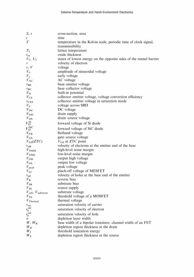
S, s cross-section, areat timeT temperature in the Kelvin scale, periodic time of clock signal,
transmissibilityTL lattice temperaturetox oxide thicknessU1, U2 states of lowest energy on the opposite sides of the tunnel barrierv velocity of electronv, V voltageV0 amplitude of sinusoidal voltageVa early voltageVAC AC voltagevBE base–emitter voltagevBC base–collector voltageVbi built-in potentialVCE collector–emitter voltage, voltage conversion efficiencyvCES collector–emitter voltage in saturation modeVd voltage across SBDVDC DC voltageVDD drain supplyVDS drain–source voltage
VDSi forward voltage of Si diode
VDSiC forward voltage of SiC diode
VFB flatband voltageVGS gate–source voltageVGS(ZTC) VGS at ZTC pointvnB velocity of electrons at the emitter end of the baseVNMH high-level noise marginVNML low-level noise marginVOH output high voltageVOL output low voltageVpeak peak voltageVpo pinch-off voltage of MESFETvpE velocity of holes at the base end of the emitterVR reverse biasVSB substrate biasVSS source supplyVsub, Vsubstrate substrate voltageVTh threshold voltage of a MOSFETVThermal thermal voltagevsat saturation velocity of carriervn
sat saturation velocity of electronvp
sat saturation velocity of holew depletion layer widthW, WB base width of a bipolar transistor, channel width of an FETWD depletion region thickness at the drainWI threshold ionization energyWS depletion region thickness at the source
Extreme-Temperature and Harsh-Environment Electronics
xxxv
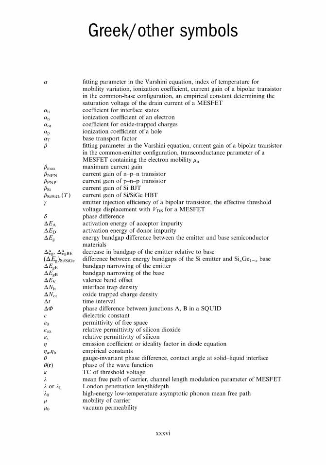
Greek/other symbols
α fitting parameter in the Varshini equation, index of temperature formobility variation, ionization coefficient, current gain of a bipolar transistorin the common-base configuration, an empirical constant determining thesaturation voltage of the drain current of a MESFET
αit coefficient for interface statesαn ionization coefficient of an electronαot coefficient for oxide-trapped chargesαp ionization coefficient of a holeαT base transport factorβ fitting parameter in the Varshini equation, current gain of a bipolar transistor
in the common-emitter configuration, transconductance parameter of aMESFET containing the electron mobility μn
βmax maximum current gainβNPN current gain of n–p–n transistorβPNP current gain of p–n–p transistorβSi current gain of Si BJTβSi/SiGe(T ) current gain of Si/SiGe HBTγ emitter injection efficiency of a bipolar transistor, the effective threshold
voltage displacement with VDS for a MESFETδ phase differenceΔEA activation energy of acceptor impurityΔED activation energy of donor impurityΔEg energy bandgap difference between the emitter and base semiconductor
materialsΔξg, ΔξgBE decrease in bandgap of the emitter relative to baseΔE( )g Si/SiGe difference between energy bandgaps of the Si emitter and SixGe1−x baseΔEgE bandgap narrowing of the emitterΔEgB bandgap narrowing of the baseΔEV valence band offsetΔNit interface trap densityΔNot oxide trapped charge densityΔt time intervalΔΦ phase difference between junctions A, B in a SQUIDε dielectric constantε0 permittivity of free spaceεox relative permittivity of silicon dioxideεs relative permittivity of siliconη emission coefficient or ideality factor in diode equationηa,ηb empirical constantsθ gauge-invariant phase difference, contact angle at solid–liquid interfaceθ(r) phase of the wave functionκ TC of threshold voltageλ mean free path of carrier, channel length modulation parameter of MESFETλ or λL London penetration length/depthλ0 high-energy low-temperature asymptotic phonon mean free pathμ mobility of carrierμ0 vacuum permeability
xxxvi
μi initial mobilityμI ionized impurity scattering-limited mobilityμf final mobilityμL lattice scattering-limited mobilityμn mobility of an electronμnB mobility of electrons in the baseμp mobility of a holeμpE mobility of holes in the emitterξ coherence length (for Cooper pairs)ξg bandgap in the emitterΞ an integerρ resistivity of a substanceρ1,ρ2 densities of the Cooper pairsρox charge density in the oxideρ(r) Cooper pair concentration in the superconductor where r is the position vectorσ conductivityσv an empirical constantτ carrier lifetime, time constantτB base transit timeτE emitter transit timeτF forward transit time, final lifetimeτHL high-level lifetimeτI initial lifetimeτLL low-level lifetimeτp lifetime of holesτpE lifetime of holes in the emitterϕ fluenceϕ phase difference between the wavefunctions ψ1 and ψ2; ϕ = ϕ2 − ϕ1
ϕ1, ϕ2 phases of the wavefunctions of Cooper pairsϕ0 phase difference when V = 0Φ magnetic flux threading a loopΦA1, ΦA2 phases adjacent to the junction A in a SQUIDΦB1, ΦB2 phases adjacent to the junction B in a SQUIDΦA, ΦB phase differences across the JJs A and B in a SQUIDϕB Schottky barrier heightΦbn Schottky barrier height of metal–semiconductor interfaceΦ0 magnetic flux quantum (fluxon)ΦExternal external magnetic fluxϕF bulk potentialϕms metal–semiconductor work functionψ wavefunctionψ1 and ψ2 wavefunctions of Cooper pairsψ(r) wavefunction of Cooper pair electron where r is the position vectorω angular frequencyωn natural angular frequencyΩ ohmΩs excitation frequency∇ nabla (differential operator)
Extreme-Temperature and Harsh-Environment Electronics
xxxvii

![MP 6503/7503/9003 (Ricoh/Savin/Lanier/nashuatec/Rex ......MP 6503/7503/9003 (Ricoh/Savin/Lanier/nashuatec/Rex ... ... が、[: ]](https://img.pdfslide.net/doc/110x75/60886e8381211f521e4cf921/mp-650375039003-ricohsavinlaniernashuatecrex-mp-650375039003-ricohsavinlaniernashuatecrex.jpg)