Embed Size (px)
Citation preview


Page 4
This guide relates to the following GPS CHART PLOTTERS:CP180, CP180i, CP190i, CP300, CP300i, CPV350, CP390i, CP500, CP590 and CPV550.
For older GPS Chart Plotters, the manual is available for download atwww.standardhorizon.com or by contacting Marine Product Support at 800-767-2450 ext 6800.
FCC Compliance Statement
This device complies with Part 15 of the FCC limits for Class A digital devices. Thisequipment generates, uses and can radiate radio frequency energy and, if notinstalled or used in accordance with the instructions may cause harmful interferencewith radio communications.There is no guarantee that interference will not occur in a particular instance. If thisequipment does cause harmful interference to other equipment, try to correct theproblem by relocating the equipment.
Consult an authorized STANDARD HORIZON dealer or other qualified servicetechnician if the problem cannot be corrected. Operation is subject to the followingconditions: (1) This device cannot cause harmful interference, and (2) this devicemust accept any interference received, including interference that may causeundesired operation.
CAUTION
· The FF525 contains dangerous high-voltage circuits which only experiencedtechnicians can handle.
· STANDARD HORIZON will not be liable for errors contained herein, or forincidental or consequential damages in connection with the performance or useof this material.
· Because we frequently update our software and applications, the pictures shownthrough this Owner’s Manual may be slightly different from what you see.
WARNING
· When plugging in or unplugging a transducer to the FF525 make sure power isturned off.
Copyright 2013. YAESU MUSEN CO., LTD. All rights reserved. Printed in Italy.
No portion of this manual may be reproduced without the permission of YAESU MUSEN CO., LTD.
CODE: Operation Manual - Issue E - 100413e
WARNING
· This Owner' Manual is for GPS Chart Plotters with software version 16.50 andlater.

CP and FF525 Operation Manual Page 5
TABLE OF CONTENTS
1. INTRODUCTION ........................................................................................................ 71.0 CONVENTIONS USED ..................................................................................... 71.1 CHART PLOTTERS .......................................................................................... 71.2 GENERAL INFORMATION ............................................................................... 7
Product Support Inquiries ................................................................................. 72. CONNECTING THE FF525 ................................................................................................... 8
2.0 SOFTWARE SETUP ........................................................................................ 82.1 CP180/CP180i/CP190i ..................................................................................... 82.2 CP300/CP300i/CP390i ..................................................................................... 92.3 CPV350 ........................................................................................................ 92.4 CP500/CP590 ................................................................................................. 102.5 CPV550 ...................................................................................................... 10
3. OPERATION ...................................................................................................... 113.0 UNDERSTANDING THE FISH FINDER PAGE ............................................. 113.1 UNDERSTANDING THE FISH FINDER DISPLAY ........................................ 133.2 DISPLAYING THE FISH FINDER PAGE ....................................................... 13
3.2.0 Auto Full Page .................................................................................... 143.2.1 200kHz Full, 50kHz Full and 50&200kHz Display Pages .................. 143.2.2 200kHz and 50kHz Zoom Pages ....................................................... 153.2.3 200kHz and 50kHz Fish/Chart Pages ............................................... 15
Focus on FISH/CHART Page ............................................................ 16Focus Soft Key on FISH/CHART Page (except CP180/CP180i/CP190i) 16
3.2.4 Radar Pages (except CP180/CP180i/CP190i) .............................................. 16FISH/RADAR/CHART Page .............................................................. 16RADAR COMBO Page ....................................................................... 16Focus Soft Key ................................................................................... 17
3.3 SOFT KEY OPERATION (except CP180/CP180i/CP190i) ....................................... 173.3.1 Customizing the Soft Keys ................................................................. 18
4. FISH FINDER SETUP MENU .................................................................................... 194.0 FISH FINDER COLOR .................................................................................... 194.1 PRESETS ...................................................................................................... 194.2 FREQUENCY .................................................................................................. 204.3 GAIN MODE .................................................................................................... 20
4.3.0 Auto Mode .......................................................................................... 214.3.1 Manual Mode ...................................................................................... 21
4.4 RANGE MENU ................................................................................................ 214.4.0 Range Mode ....................................................................................... 214.4.1 Depth .................................................................................................. 214.4.2 Shift .................................................................................................... 21
4.5 INTERFERENCE REJECTION ...................................................................... 224.6 SENSITIVITY MENU ...................................................................................... 22
4.6.0 Gain .................................................................................................... 224.6.1 STC (Sensitivity Time Control) .......................................................... 234.6.2 Surface Noise Filter ........................................................................... 24
4.7 DISPLAY SETUP ............................................................................................ 244.7.0 Color Settings ..................................................................................... 254.7.1 Scrolling Speed .................................................................................. 25

Page 6
4.7.2 White Line .......................................................................................... 254.7.3 Fish Symbols ...................................................................................... 254.7.4 A-Scope .............................................................................................. 254.7.5 Water Temperature ............................................................................ 25
4.8 TRANSDUCER SETUP .................................................................................. 264.8.0 Keel Offset ......................................................................................... 264.8.1 Calibrate Water Speed ....................................................................... 264.8.2 Calibrate Water Temp ........................................................................ 264.8.3 Calibrate Aux Temp ........................................................................... 264.8.4 Set Defaults ........................................................................................ 26
4.9 ALARMS ...................................................................................................... 264.9.0 Shallow Water .................................................................................... 274.9.1 Deep Water ........................................................................................ 274.9.2 Fish ..................................................................................................... 274.9.3 Temperature Upper ............................................................................ 274.9.4 Temperature Lower ............................................................................ 274.9.5 Temperature Rate .............................................................................. 27
4.10 SAVE SETTINGS TO USER C-CARD ........................................................... 274.11 LOAD SETTINGS FROM USER C-CARD ..................................................... 284.12 RESTORE CURRENT PRESET DEFAULTS ................................................ 28
5. OPERATION TIPS ..................................................................................................... 29INDEX ...................................................................................................... 32

CP and FF525 Operation Manual Page 7
1. INTRODUCTION
This manual provides basic information in becoming familiar with the advanced functionsof the FF525 before you start using it combined with the STANDARD HORIZON GPS ChartPlotters.
1.0 CONVENTIONS USED
Please refer to the legend below:
[MENU] If you see brackets around a bold and capital letter word this refers to a key press.
[CHART] If you see brackets around a bold and small capital letter word this refers to a Soft Keypress.
GENERAL SETUP When a word(s) is in bold capital letters and underlined, this refers to a menu selectionitem.
1.1 CHART PLOTTERS
Any menu operation and functions activation in this Operation Manual is related to thefollowing Chart Plotter models with software capable to operate with FF525. Whenever itis necessary, a note has been inserted for those models with operational differences.
· CP180· CP180i· CP190i· CP300· CP300i· CP390i· CPV350· CP500· CP590· CPV550
1.2 GENERAL INFORMATION
PRODUCT SUPPORT INQUIRIESIf you have any questions or comments:
· USA customers should contact STANDARD HORIZON at 714-827-7600 or by [email protected].
· UK customers should contact STANDARD HORIZON at 01962 866667 or [email protected].
· European customers should contact their local dealer or distributor for support.
Page 8
2. CONNECTING THE FF525
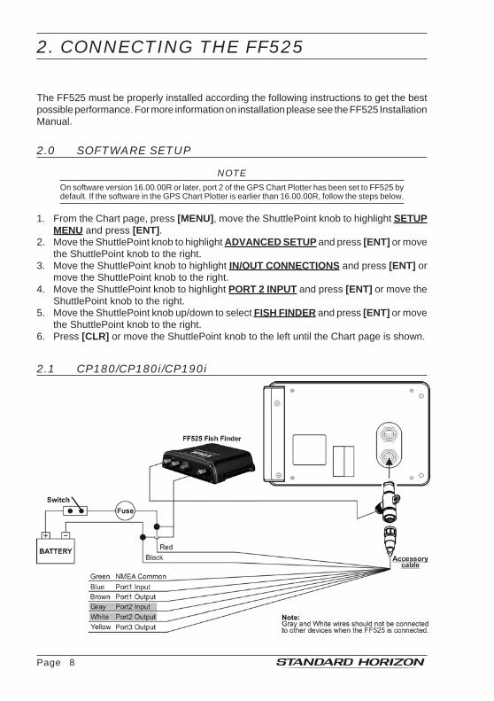
The FF525 must be properly installed according the following instructions to get the bestpossible performance. For more information on installation please see the FF525 InstallationManual.
2.0 SOFTWARE SETUP
NOTEOn software version 16.00.00R or later, port 2 of the GPS Chart Plotter has been set to FF525 bydefault. If the software in the GPS Chart Plotter is earlier than 16.00.00R, follow the steps below.
1. From the Chart page, press [MENU], move the ShuttlePoint knob to highlight SETUPMENU and press [ENT].
2. Move the ShuttlePoint knob to highlight ADVANCED SETUP and press [ENT] or movethe ShuttlePoint knob to the right.
3. Move the ShuttlePoint knob to highlight IN/OUT CONNECTIONS and press [ENT] ormove the ShuttlePoint knob to the right.
4. Move the ShuttlePoint knob to highlight PORT 2 INPUT and press [ENT] or move theShuttlePoint knob to the right.
5. Move the ShuttlePoint knob up/down to select FISH FINDER and press [ENT] or movethe ShuttlePoint knob to the right.
6. Press [CLR] or move the ShuttlePoint knob to the left until the Chart page is shown.
2.1 CP180/CP180i/CP190i

CP and FF525 Operation Manual Page 9
2.2 CP300/CP300i/CP390i
2.3 CPV350

Page 10
2.4 CP500/CP590
2.5 CPV550

CP and FF525 Operation Manual Page 11
3. OPERATION
3.0 UNDERSTANDING THE FISH FINDER PAGE
The display on STANDARD HORIZON GPS Chart Plotters shows a history of time of theechoes received by the transducer. The STANDARD HORIZON GPS Chart Plotters havea menu that allows adjustments to receiver sensitivity, depth range and scrolling speed ofthe Fish Finder display.
Figure 3.0 - The Fish Finder page
The following is a brief description of terms listed in the previous Figure:
Warning MessageFlashing label that is turned On when the echo sounder is in Simulation mode.The following is the list of the Warning messages:
· SHALLOW WATER ALARM· DEEP WATER ALARM· HIGH WATER TEMP ALARM· LOW WATER TEMP ALARM· WATER TEMP RATE ALARM· FISH SPOT· NO DATA, problem with connection between CP and Fish Finder Tee Cable
Fish Finder windowGraphic presentation of sonar soundings recorded as a continuous bottom scrollingacross the screen from right to left. Such recordings represent the image of the waterbeneath your boat, items appear as they pass under your transducer; the items on theright side of the screen are closer to you than those on the left. The correct interpretationof the Fish Finder page allows retrieving useful information about what is under theboat.

Page 12
Digital DepthReadout of the current bottom depth.
Water TemperatureReadout of the current water temperature returned by the temperature sensor includedin DST520, DST521, DST523, DST525, DST526, DST527, DST528A.
Shallow Alarm BarLocated on the right side of the Range Bar, the Shallow Alarm Bar shows the rangeoutside of which the depth measurement will trigger a Shallow Alarm.
Range BarVertical graduated bar, located along the right side of the screen. It is a scale whichreflects the depth of the area being displayed.
Variable Depth Marker (VDM)Horizontal line onto the Fish Finder page window with a depth label. Move theShuttlePoint knob Up or Down to change the position of the VDM. The label displaysthe depth of the cursor position. The VDM can be moved to any location pinpointing thedepth of a target.
A-ScopeReal time representation of fish and bottom features passing through the beam of thetransducer, drawn as column of horizontal lines whose length and hue is proportionalto the echo strength returned. The color of the echo strength depends on the selecteddisplay color. When the default palette is selected, the strongest sonar returns will beshown as red and weaker returns will be shown blue.
Deep Alarm BarBar located on the left side of the Range Bar, showing the portion of the Echogramcurrently represented in the zoomed window (on the left part of the screen). It is turnedOn selecting the Echosounder Split page.
Transmit FrequencyShows the selected depth transmit frequency. As a reference, 200kHz selection isnormally used to see targets in depth up to 400 ft, and 50kHz is used in water over 400 ft.
Color Bar1
Colored scale located on the left side of the screen that shows the colors used in theFish Finder page to represent the echoes strength. The color on the top of the barFF525 represents the maximum echo strength, while the color on the bottom of the barrepresents the minimum echo strength.
NOTEColor Bar is displayed only if the Fish Finder is in 16 colors (not 256 colors) mode. Refer to Par. 4.0FISH FINDER COLOR to change the color.

CP and FF525 Operation Manual Page 13
3.1 UNDERSTANDING THE FISH FINDER DISPLAY
Figure 3.1 - The Fish Finder display
FishFish are usually represented by small dots on the display when using 200kHz and byarches when using 50kHz.
ThermoclineAre the zones where two layers of different water temperatures meet. The greater thetemperature differential, the denser the thermocline shows on the screen. Thermo-clines are represented as horizontal stripes of noise. They are very important for fishingsince often many species of game fish like to suspend in, just above, or just below thethermoclines.
White LineThe White Line shows the difference between hard, soft bottoms and even distinguish-es between fish and structures located near the bottom. In this way it is easier to tellthe difference between a hard and soft bottom and even to distinguish fish andstructures located nearby the bottom.
Surface ClutterAppears like noise at the top of the screen extending many feet below the surface. It’scaused by many things, including air bubbles, bait fish, plankton and algae.
StructuresGenerally, the term “structure” is used to identify objects like wrecks and weeds risingfrom the bottom.
Bottom Echo ProfileBottom profile recorded by the FF525. When the echo sounder is set in Auto Rangemode, the bottom is kept in the lower half in the display.
3.2 DISPLAYING THE FISH FINDER PAGE
This section explains how to show and customize the selection of the Fish Finder displaypages.
1. Press [MENU], if on the Fish Finder page press [MENU] two times.

Page 14
Figure 3.2 - Example of Main Menu on CP590
2. Move the ShuttlePoint knob to highlight FISH FINDER (or RADAR/FISH depending onthe GPS Chart Plotter) and press [ENT].
Figure 3.2a - Example of Fish Finder Page Selection menu on CP590
3. Move the ShuttlePoint knob to select the desired display and press [ENT]. The pageoptions are shown in the following paragraphs.
3.2.0 Auto Full PageWhen this page is selected, the FF525 automatically changes the transmit frequency toshow depths. Automatic switching occurs when depth of water is less than 400 ft (200kHz)and greater than 400 ft (50kHz).
3.2.1 200kHz Full, 50kHz Full and 50&200kHz Display PagesAllows the user to setup the GPS Chart Plotters display to show 200kHz, 50kHz or200/50kHz split screen Fish Finder.
Figure 3.2.1 - Full Display pages

CP and FF525 Operation Manual Page 15
When the 50 & 200kHz page has been selected the active window has a yellow border.Please follow the procedure below to change the focus:1. Move the ShuttlePoint knob to the right or left: the focus is changed and the focused
window has a yellow border.
3.2.2 200kHz and 50kHz Zoom PagesAllows the user to zoom into the 200kHz or 50kHz Fish Finder display to show detail of thearea selected by the VDM (Variable Depth Marker). Refering to Figure 3.2.2, the left displayshows the zoomed display and the right display shown the unzoomed display.To select the area to be zoomed in move the ShuttlePoint knob up or down which movesthe VDM line.To zoom in or out, press [ZOOM IN] or [ZOOM OUT] or, on the CPV350 and CPV550 press[ZOOM] and rotate the channel knob.The zoom ranges are 2x and 4x the normal Fish Finder display.
Figure 3.2.2 - Zoom Full Page
3.2.3 200kHz and 50kHz Fish/Chart PagesSelects the display to show the Chart page on the left half of the screen and the Fish Finderon the right half of the screen. 200kHz or 50kHz Fish Finder can be selected on the righthalf of the display.
Figure 3.2.3 - Fish/Chart Page
With the focus on the Chart page the cursor may be moved and all chart menus can beselected. When focus is on the Fish Finder window the Variable Range Marker can bemoved to see the depths of targets and Fish Finder menus can be accessed.

Page 16
Focus on FISH/CHART PageWhen the Fish/Chart page has been selected please follow the procedure below to placethe focus on the Chart page or on the Fish Finder window:
NOTE FOR CP500/CP590In the procedure below the [FIND] key is called [INFO].
1. Press and hold [FIND] for 2 seconds: a popup window appears wheare the active focuswindow label is highlighted.
2. Move the ShuttlePoint knob up and down and press [ENT]. The focus is changed.
Focus Soft Key on FISH/CHART Page (EXCEPT CP180/CP180i/CP190i)
1. Press one of the Soft Keys under the display. The Soft Key labels appear on the bottomof the screen. A [FOCUS] Soft Key will be shown.
2. Press [FOCUS] to show the Focus popup window, where the active focus window labelis highlighted.
3. Select CHART or FISH FINDER using the ShuttlePoint knob and press [ENT].
Figure 3.2.3a - Example of Chart/Fish page with [FOCUS] shown on CP390i (on the left side)
and with Focus popup window (on the right side)
3.2.4 Radar Pages (EXCEPT CP180/CP180i/CP190i)
FISH/RADAR/CHART PageSelects the GPS Chart Plotters display to show the Chart, the Fish Finder and the Radarpage on the screen.
Figure 3.2.4 - Fish/Radar/Chart page on CP390i
RADAR COMBO PageSelects the GPS Chart Plotters display to show the Chart, the Fish Finder, the Radar andthe Highway page on the screen.

CP and FF525 Operation Manual Page 17
Figure 3.2.4a - Radar Combo page on CP390i
FOCUS Soft KeyWhen the Fish/Radar/Chart page or the Combo page has been selected, the active windowis highlighted a "red" border around the window. The keyboard commands are related to thatfocused view. To move the focus to a different window follow the procedure:1. Press any Soft Key. The Soft Key labels appear on the bottom of the screen. A [FOCUS]
Soft Key will be shown.2. Press [Focus]. A popup window appears where the active focus window label is
highlighted.
NOTEIt is possible to change the focus by pressing and holding [FIND] (or [INFO] for CP500/CP590) for2 seconds (in place of 1 and 2 steps in the previous procedure).
Figure 3.2.4b - Example of Combo Page with [FOCUS] shown on CP390i
3. Move the ShuttlePoint knob to highlight the desired window and press [ENT]. The redborder is moved to the focused window.
NOTEWhen the focused window (identified by the red border) is the Fish Finder page and the selectedFish Finder page is the 50 & 200kHz, it is possible to change the active FF sub-window (identifiedby the yellow border). To change the focus between the 50kHz and 200kHz sub-windows pleasemove the ShuttlePoint knob to the right or left, the focus is changed and the focused window hasa yellow border (see also Par. 3.2.1).
3.3 SOFT KEY OPERATION (except CP180/CP180i/CP190i)
1. Press any of the Soft Keys to show the key descriptions, then press the [200KHZ] SoftKey if it has been customized (for detail see the next paragraph).

Page 18
Figure 3.3 - Example of Fish Finder page selection by Soft Keys on CP390i
3.3.1 Customizing the Soft KeysTo customize a Soft Key, from Chart page:1. Press any of the Soft Keys.2. Press and hold the Soft Key you want to customize. A popup window will be shown with
the avalaible settings:
Figure 3.3.1 - Customizing Soft Keys on CP390i
3. Move the ShuttlePoint knob to the desired Fish Finder page.4. Press [ENT] or move the ShuttlePoint knob to the right to save the desired Fish Finder
page to the selected Soft Key.

CP and FF525 Operation Manual Page 19
4. FISH FINDER SETUP MENU
This section explains how to show the Fish Finder Setup menu and describe the Fish FinderSetup menu sub-options.1. From the Full Fish Finder page, press [MENU]. The following menu appears:
Figure 4 - Fish Finder Setup menu
4.0 FISH FINDER COLOR
Allows you to choose the Fish Finder color between 16 colors and 256 colors.
Figure 4.0 - Fish Finder Color menu
4.1 PRESETS
To simplfy menu selections, the FF525 has two presets that can be easily selected forfishing (Fish) or cruising (Cruise):

Page 20
Figure 4.1 - Presets menu (left) and table (right)
NOTEFor Gain and Gain Offset settings refer to Sensitivity menu (see Par. 4.3).
For Range and Shift settings refer to Range menu (see Par. 4.4).
4.2 FREQUENCY
Allows you to choose the Frequency among Auto, 50kHz, 200kHz or 50&200kHz.
Figure 4.2 - Frequency menu
4.3 GAIN MODE
Figure 4.3 - Gain Mode menu

CP and FF525 Operation Manual Page 21
4.3.0 Auto ModeAllows the Fish Finder to automatically adjust receiver Gain depending on water depth.
4.3.1 Manual ModeAllows the user to change the Gain manually to fine tune the FF525’s receiver.
4.4 RANGE MENU
Figure 4.4 - Range menu
4.4.0 Range ModeSelects among Manual, Auto Range and Bottom Lock.
· ManualUsed to set the depth Range (from the surface) the Fish Finder display will show.
· Auto RangeThe Fish Finder automatically determines the Range to keep the bottom visible in thelower bottom of the screen. In this mode, Shift is always set to 0.
· Bottom LockThe Bottom Lock function keeps the screen display locked onto a certain Range aroundthe bottom. Let’s say the bottom is 400 ft and the Bottom Lock Range is set to display30 ft around the bottom, the screen (instead of displaying from 0 ft to e.g. 450 ft) willdisplay only a Range of 30 ft around the bottom, e.g. from 380 ft to 410 ft.
4.4.1 DepthMoves the display from showing the bottom to the depth value entered.
4.4.2 ShiftShifts the display from the bottom of the transducer to the depth value entered.Example: Your vessel is in about 57 ft of water, however there is fish suspended in 35 ft
of water. You want to display to 10 ft area around the fish. Shift would be set to30 ft and Depth would be set to 40 ft shown in the following example.

Page 22
Figure 4.4.2 - Example of Depth and Shift
4.5 INTERFERENCE REJECTION
Turns On or Off a filter to remove noise from other Fish Finder or Depth Sounders.
Figure 4.5 - Interference Rejection menu
4.6 SENSITIVITY MENU
All settings in the Sensitivity menu are related to the selected Fish Finder transmit frequency(50kHz or 200kHz).
Figure 4.6 - Sensitivity menu
4.6.0 GainAllows you to control the Sensitivity of the unit’s receiver from 0 to 100%. To see more detail,increase the receiver Sensitivity by selecting a higher Gain percentage. If there is too muchdetail or if the screen is cluttered, lowering the Sensitivity may increase the clarity of thedisplay.
NOTEWhen the Gain Mode option is set to Auto, the receivers Gain cannot be changed.
When the Gain Mode option is set to Manual, the Gain can be manually adjusted. When switchingfrom Automatic to Manual Mode, the Gain + Offset value is copied into the Manual Gain setting ofthe receiver.
CP and FF525 Operation Manual Page 23
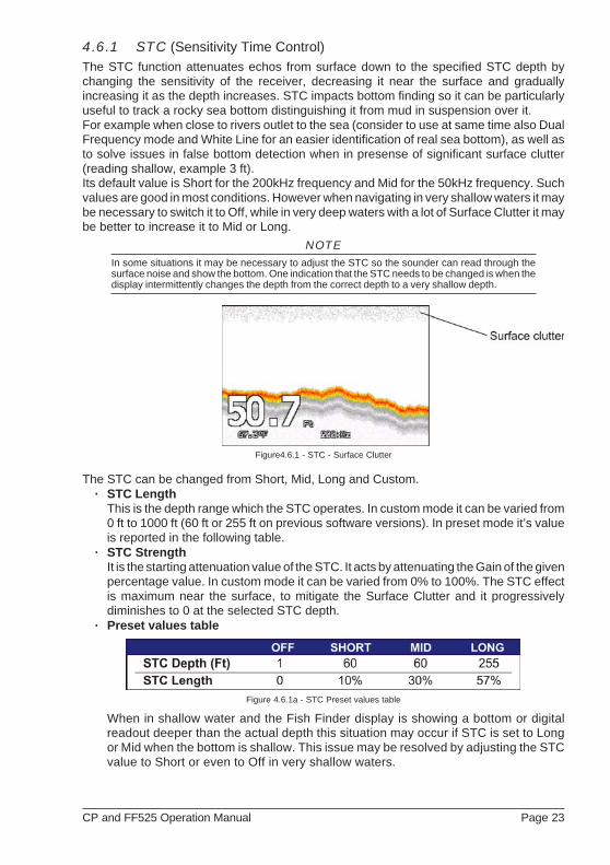
4.6.1 STC (Sensitivity Time Control)
The STC function attenuates echos from surface down to the specified STC depth bychanging the sensitivity of the receiver, decreasing it near the surface and graduallyincreasing it as the depth increases. STC impacts bottom finding so it can be particularlyuseful to track a rocky sea bottom distinguishing it from mud in suspension over it.For example when close to rivers outlet to the sea (consider to use at same time also DualFrequency mode and White Line for an easier identification of real sea bottom), as well asto solve issues in false bottom detection when in presense of significant surface clutter(reading shallow, example 3 ft).Its default value is Short for the 200kHz frequency and Mid for the 50kHz frequency. Suchvalues are good in most conditions. However when navigating in very shallow waters it maybe necessary to switch it to Off, while in very deep waters with a lot of Surface Clutter it maybe better to increase it to Mid or Long.
NOTEIn some situations it may be necessary to adjust the STC so the sounder can read through thesurface noise and show the bottom. One indication that the STC needs to be changed is when thedisplay intermittently changes the depth from the correct depth to a very shallow depth.
Figure4.6.1 - STC - Surface Clutter
The STC can be changed from Short, Mid, Long and Custom.· STC Length
This is the depth range which the STC operates. In custom mode it can be varied from0 ft to 1000 ft (60 ft or 255 ft on previous software versions). In preset mode it’s valueis reported in the following table.
· STC StrengthIt is the starting attenuation value of the STC. It acts by attenuating the Gain of the givenpercentage value. In custom mode it can be varied from 0% to 100%. The STC effectis maximum near the surface, to mitigate the Surface Clutter and it progressivelydiminishes to 0 at the selected STC depth.
· Preset values table
Figure 4.6.1a - STC Preset values table
When in shallow water and the Fish Finder display is showing a bottom or digitalreadout deeper than the actual depth this situation may occur if STC is set to Longor Mid when the bottom is shallow. This issue may be resolved by adjusting the STCvalue to Short or even to Off in very shallow waters.

Page 24
When in Deep Water the Fish Finder display is showing a very shallow bottom ordigital readout this may happen because in conditions of strong Surface Clutter theFish Finder may erroneously look on to the Surface Clutter. To solve this situation tryto increase the STC to Long or to Custom increasing the STC length and strength.When in Deep Water the Fish Finder doesn’t see the bottom, this may happenbecause the bottom is out of range or is very near to the maximum depth that can betracked by the Fish Finder. In the latter case this may happen if the bottomcomposition is soft as mud, if the sea conditions are bad, there are thermoclines orthe water is full of suspended materials (silt, plankton). All these factors may affectconsiderably the performance of the Fish Finder to be able to see the bottom. In thesecases change the Range Mode from Auto to Manual Range and manually adjust thedepth range until the bottom echo becomes visible on the Fish Finder display.
4.6.2 Surface Noise FilterAn automatic filter that attempts to remove Surface Clutter that causes the screen to befilled up with strong return echoes just below the surface. It may seem that the samefunctionality could be achieved using on the STC control however there is main differencebetween such control in fact the STC control impacts the capability to detect and track thebottom and is not designed to cancel completely the surface noise, on the other side theSurface Noise Filter attempts to cancel completely the surface noise but it doesn’t affectthe capability to detect and track the bottom. Filter gradually attenuates surface noises. TheSurface Noise Filter has 9 settings: Off, 1, ..., 8. When set to 1 the Surface Noise is attenuatedfrom surface down to a depth of 5 ft, increasing the Surface Noise increases the depth in whichthe Surface Noise is attenuated as well as the attenuation level increases; when the presetis set to 8 the attenuation is maximum and is applied from surface level down to a depth of 255ft, as shown in the Surface Noise Filter Table reported below:
Figure 4.6.2 - Surface Noise Filter Depth table
4.7 DISPLAY SETUP
Allows the Fish Finder’s display page appearance to be changed.
Figure 4.7 - Display Setup menu

CP and FF525 Operation Manual Page 25
4.7.0 Color SettingsAllows you to change the color of the Fish Finder display from Blue Background (default),White Background, Black Background, Gray scale and Reversed Gray scale.
Figure 4.7.0 - White and Blue background examples
4.7.1 Scrolling SpeedControls the rate the Fish Finder scrolls and updates the Fish Finder display.
4.7.2 White LineControls how the bottom type (hard or soft) is shown on the display. When the White Lineis Off the bottom return will display as red. When the White Line is On it can be used todetermine bottom hardness.
NOTEThe White Line option is not available in the 50 & 200kHz page.
4.7.3 Fish SymbolsControls the graphical representation of underwater-suspended targets.Echo : shown as arches (echoes)Icon + Echo : shown as arches with the Fish iconIcon + Echo + Depth : shown as arches with the Fish icon and relative depth valuesEcho + Depth : shown depth valuesIcon : shown as Fish icons without the archesIcon + Depth : shown as Fish icons and their relative depth values (shown accord-
ingly to currently selected depth unit)
4.7.4 A-ScopeShows the real time display of the echo from the bottom.
4.7.5 Water TemperatureAllows selection between:
· the temperature sensor in the depth transduceror
· an external temperature sensor connected to the optional connection wires.

Page 26
4.8 TRANSDUCER SETUP
This menu allows you to calibrate the speed through the water, water temperature and thekeel/prop offset of the transducer.
Figure 4.8 - Transducer Setup menu
4.8.0 Keel OffsetThe keel offset can be set to cause the Fish Finder to display an offset depth below the keelor the actual water depth from the surface. To setup to show the depth below the keel, entera negative depth value or a positive depth to show offset from the transducers face to thewater surface.
4.8.1 Calibrate Water SpeedUsed to calibrate the Water Speed readings from the transducer. Adjustment can be madefrom -10% to +10%.
4.8.2 Calibrate Water TempUsed to calibration on the Water Temperature sensor in the transducer.
4.8.3 Calibrate Aux TempAllows the calibration of the Auxialiary Temperature sensor connected to the optionalconnection wires.
4.8.4 Set DefaultsRestores the factory settings.
4.9 ALARMS
The Alarms menu allows you to define alarm settings for Shallow Alarm, Depth Alarm andTemperature Upper/Lower/Rate.

CP and FF525 Operation Manual Page 27
Figure 4.9 - Alarms menu
To set an Anchor Alarm, enter in a shallow water and deep water value above and belowyour actual anchoring depth. The alarm will sound when the depth becomes shallower ordeeper than the settings.
4.9.0 Shallow WaterTriggers an alarm when depth becomes shallower than the set depth.
4.9.1 Deep WaterTriggers an alarm when depth becomes deeper than the set depth.
4.9.2 FishThe Fish Alarm can be set to detect and alert you depending on the size of fish. The optionsare: Off, Small, Medium, Big and Huge. The alarm sounds if the set size (or bigger) isdetected.
4.9.3 Temperature UpperTriggers an alarm when the transducer reports a temperature above the set temperature.
4.9.4 Temperature LowerTriggers an alarm when the transducer reports a temperature below the set temperature.
4.9.5 Temperature RateTriggers an alarm when the transducer reports a temperature variation rate above the settemperature.
4.10 SAVE SETTINGS TO USER C-CARD
This option saves the complete set of Fish Finder settings to an optional User C-CARD. Thisis useful to avoid the user having to retune up Fish Finder after a RAM Clear operation ora software update.

Page 28
Figure 4.10 - C-CARD - Save settings
4.11 LOAD SETTINGS FROM USER C-CARD
This option loads the complete set of Fish Finder settings from the User C-CARD (MemoryCard that may be used to backup the User Points and Tracks too).
Figure 4.11 - C-CARD - Load settings
4.12 RESTORE CURRENT PRESET DEFAULTS
This option restores the default values only for the current presets (see Par. 4.1, Presets)and does not affect the other presets.
Figure 4.12 - C-CARD - Restore settings

CP and FF525 Operation Manual Page 29
5. OPERATION TIPS
5.0 How can I set optimal operating parameters?Optimal operating parameters can be set accordingly with the intended use of the FishFinder, to quickly get optimal operational parameters for fishing it is may be best to selectthe Fish preset from the Fish Finder Setup menu, while for cruising it is may be best to selectthe Cruise preset.
5.1 What are preset modes?Preset modes are pre-defined settings of the Fish Finder operating parameters. You canuse them to quickly set the Fish Finder in the most commonly used operating modes.These are:
· Cruise : sets Fish Finder in Full Auto mode with the Sensitivity settings (Gain Offset,Noise level and STC) optimized for displaying the bottom while underway.
· Fish : sets the Fish Finder in Full Auto mode with the Sensitivity setting optimizedfor fish finding.
5.2 How can I restore the Fish Finder to factory default settings?While the Fish Finder page is shown, press [MENU] and move the ShuttlePoint knob toTransducer Setup and press [ENT]. Move the ShuttlePoint knob to Set Defaults and press[ENT]. Press [CONFIRM] on the CP300/CP300i, CP390i, CPV350, CP500, CP590 andCPV550, or on the CP180/CP180i and CP190i press [ENT]. Note that this operation set alldefault settings, not only the working defaults.
5.3 Can I always leave the Fish Finder in Full Auto (Auto Gain and AutoRange) mode?
Yes, but note that the Full Auto mode suits the 90% of the cases, however in extremesituations the Auto modes may fail and thus it is necessary to switch to the Manual mode.
5.4 What are extreme situations in which Auto modes may fail?When the bottom is very deep, at high boat speed, when the bottom is very shallow (< 5ft),when the water is full of materials in suspension, with bad sea conditions.
5.5 What should I do if the Auto modes fail?Failure of Auto modes can happen for various reasons. Hereafter you can find a range ofpossibilities.
5.6 Auto Range fails in very shallow waters displaying a digital depthreadout deeper than the actual value. What should I do?
This usually happens if the STC is set to Long or Mid and the bottom is shallow or Shortif the bottom is very shallow causing the Auto Range to hook to the second or third echo fromthe bottom (since in shallow waters the sound bounces more times back and forth thesurface to the bottom). Try decreasing the STC value to Short in shallow waters or to switchit to very Short or Off.

Page 30
5.7 Auto Range fails, and the digital depth readout displays a very shallowreading. What should I do?
This usually happens if the STC is Off or is set to a low value causing disturbance fromSurface Clutter to be stronger than bottom echoes. Try increasing the STC value. Asgeneral rule STC has to be set as in shallow waters and Long in depth waters.
5.8 Auto Range fails in very deep waters displaying a digital very shallowdepth readout. What should I do?
The Fish Finder capability to detect the bottom decreases as the bottom depth increase. Ifthe bottom composition is soft as mud, if the sea conditions are bad, if there are thermoclinesor the water is full of materials in suspension it can further decrease thus causing the digitaldepth readout to fail. When this happens the Auto Range algorithm also fails. To recoverfrom this situation it is necessary to switch to Manual Range mode and to set the ManualDepth mode. When Manual Depth mode is selected the algorithm that calculates the digitaldepth readout searches for the bottom within the range manually selected by the user. Atthis point it is necessary to increase manually the Range until the bottom becomesgraphically visible. If the echoes from the bottom are strong enough, the Fish Finder shalllook to the bottom giving a correct depth reading and shall be possible to return in AutoRange mode. Please note that if one or more of the conditions that reduce the echoes fromthe bottom listed above is true the bottom may be not visible at all, in this situation a strongthermocline or Surface Clutter may be interpreted by the Fish Finder as the bottom.
5.9 At a very shallow range upper half of the screen appears almostcompletely filled by the Surface Clutter. How can I eliminate it?
This is normal in shallow waters. To clean up the Surface Clutter without degrading thedigital depth readout algorithm functionality there are two modes:1. If Surface Declutter = Off it is possible to set the STC value to custom setting the STC
length to the same size of the Surface Clutter, and increasing the STC strength until theimage on the screen cleans up. Please note that in very shallow waters it is usually betterto switch to Manual Gain mode to reduce Gain fluctuation due to rapidly changingbottom conditions.
2. Using Surface Declutter, increase the Surface Declutter value until the SurfaceDeclutter disappears completely.
5.10 Why do I never see fish in the range between 0 to 2 ft?The minimum range of the Fish Finder is 2 ft. In this interval the Fish Finder can detectneither the bottom nor any target.
5.11 How can I reduce the Surface Clutter?You can act by: properly setting the STC as described at 5.9 and also by increasing theNoise Level and reducing the Gain or the Gain Offset (if you are in Auto Gain mode).However please note that a strong attenuation of Surface Clutter may also reduce thecapability to detect targets.
5.12 The Fish Finder is in Auto Gain mode but the picture display too manysmall targets, what shall I do to reduce the screen clutter?
Try increasing the Noise Level or decreasing the Gain Offset.

CP and FF525 Operation Manual Page 31
5.13 In very shallow waters when the Auto Gain mode is selected there arefluctuations in the bottom profile width and its color representation.What should I do?
In very shallow waters the environment situation (bottom/water condition) changes veryquickly thus causing the Auto Gain algorithm to create oscillations while trying to set optimalGain value for each situation. To avoid this it is advisable to switch to Manual Gain modeand fine tune the Gain to a fixed setting.
5.14 In very deep waters even setting the Gain to its maximum value I cannotsee the bottom what shall I do?
Try decreasing the Noise Level. If still the bottom is not visible there is nothing you can do,the bottom echo is simply too weak to be detected.
5.15 GPS Chart Plotter shows no data when viewing the Fish Finder page.This may be due to the FF525 having an issue. To confirm, listen to the depth transducerfor the transmit pulse. If the pulse is not heard the FF525 is defective.

Page 32
INDEX
16 colors ................................................... 12, 19200kHz ............................................................ 15200kHz Full ..................................................... 14256 colors ................................................. 12, 1950 & 200kHz page ..................................... 15, 2550&200kHz Display ......................................... 1450kHz .............................................................. 1550kHz Full ....................................................... 14
AA-Scope ................................................... 12, 25Alarm Bar ........................................................ 12Alarms menu ............................................ 26, 27Anchor Alarm .................................................. 27Auto Full Page ................................................. 14Auto Gain ........................................................ 29Auto Mode ....................................................... 21Auto Range ....................................... 21, 29, 30Auxialiary Temperature ................................... 26
BBar .................................................................. 12Bottom Echo Profile ........................................ 13Bottom Lock .................................................... 21
CC-CARD ................................................... 27, 28Calibrate Aux Temp ......................................... 26Calibrate Water Speed .................................... 26Calibrate Water Temp ..................................... 26change the focus ............................................. 15Chart Plotter models .......................................... 7Chart/Fish page ............................................... 16Color Bar ......................................................... 12Color menu ...................................................... 19Color Settings .................................................. 25Combo Page ................................................... 17CONVENTIONS ................................................ 7CP180 ...................................... 7, 8, 16, 17, 29CP180i ..................................... 7, 8, 16, 17, 29CP190i ..................................... 7, 8, 16, 17, 29CP300 ................................................... 7, 9, 29CP300i .................................................. 7, 9, 29CP390i .............................. 7, 9, 16, 17, 18, 29CP500 .................................... 7, 10, 16, 17, 29CP590 .................................... 7, 10, 16, 17, 29CPV350 ........................................... 7, 9, 15, 29CPV550 ......................................... 7, 10, 15, 29Cruise ....................................................... 19, 29Customizing the Soft Keys .............................. 18
Ddealer ................................................................ 7Deep Alarm Bar ............................................... 12Deep Water .............................................. 24, 27DEEP WATER ALARM ................................... 11Depth .......................................... 12, 21, 22, 25
Digital Depth .................................................... 12Display Setup menu ........................................ 24distributor .......................................................... 7DST520 ........................................................... 12DST521 ........................................................... 12DST523 ........................................................... 12DST525 ........................................................... 12DST526 ........................................................... 12DST527 ........................................................... 12DST528A ........................................................ 12
EEcho ................................................................ 25Echo + Depth .................................................. 25European customers ......................................... 7
Ffactory default settings ..................................... 29factory settings ................................................ 26Filter ................................................................ 24FIND ................................................................ 16Fish ............................................. 13, 19, 27, 29Fish Alarm ....................................................... 27FISH FINDER .................................................. 14FISH FINDER COLOR ............................. 12, 19Fish Finder display .......................................... 13Fish Finder page ............................................. 11Fish Finder Setup menu ........................... 19, 29Fish Finder window .......................................... 11Fish icon .......................................................... 25FISH SPOT ..................................................... 11Fish Symbols ................................................... 25Fish/Chart Page .............................................. 15focus ................................................. 15, 16, 17Focus popup window ....................................... 16Focus Soft Key ................................................ 16Frequency ................................................ 12, 20frequency ................................................. 14, 22Full Auto .......................................................... 29Full Display pages ........................................... 14
GGain ......................................................... 22, 30Gain Mode menu ............................................. 20Gain Offset ...................................................... 29
HHIGH WATER TEMP ALARM ......................... 11Highway page .................................................. 16
IIcon ................................................................. 25Icon + Depth .................................................... 25Icon + Echo ..................................................... 25Icon + Echo + Depth ........................................ 25installation ......................................................... 8Interference Rejection menu ........................... 22

CP and FF525 Operation Manual Page 33
KKeel Offset ...................................................... 26
Llegend ............................................................... 7Load settings ................................................... 28LOW WATER TEMP ALARM ......................... 11
MMain Menu ....................................................... 14Manual ............................................................ 21Manual Gain ............................................. 30, 31Manual Mode ................................................... 21Manual Range ................................................. 30
NNO DATA ........................................................ 11Noise Filter ...................................................... 24Noise Level .............................................. 30, 31
PPage Selection menu ...................................... 14port 2 ................................................................. 8Preset values table .......................................... 23presets ..................................................... 19, 28Presets menu .................................................. 20
RRadar Pages ................................................... 16RADAR/FISH .................................................. 14RAM Clear ....................................................... 27Range Bar ....................................................... 12Range menu .................................................... 21Range Mode .................................................... 24remove noise ................................................... 22Restore settings .............................................. 28
SSave settings ................................................... 28Scrolling Speed ............................................... 25Sensitivity ................................................. 22, 29Sensitivity menu .............................................. 22Sensitivity Time Control ................................... 23Set Defaults ..................................................... 26Setup menu .............................................. 19, 29Shallow Alarm Bar ........................................... 12
Shallow Water ................................................. 27SHALLOW WATER ALARM ........................... 11Shift .......................................................... 21, 22Soft Keys ......................................................... 17SOFTWARE SETUP ........................................ 8Speed .............................................................. 26STC ............................................. 23, 24, 29, 30STC Length ..................................................... 23STC Strength .................................................. 23Structures ........................................................ 13Surface Clutter ............................ 13, 23, 24, 30Surface Noise Filter ......................................... 24Surface Noise Filter Depth table ...................... 24
TTee Cable ........................................................ 11Temperature ................................ 12, 25, 26, 27Temperature Lower ......................................... 27Temperature Rate ........................................... 27temperature sensor ......................................... 25Temperature Upper ......................................... 27Thermocline .................................................... 13Tracks ............................................................. 28Transducer Setup menu .................................. 26Transmit Frequency ........................................ 12
UUK customers .................................................... 7USA customers ................................................. 7User C-CARD ........................................... 27, 28User Points ...................................................... 28
VVariable Depth Marker ............................. 12, 15Variable Range Marker ................................... 15VDM ......................................................... 12, 15
WWarning Message ........................................... 11Water Speed ................................................... 26WATER TEMP RATE ALARM ........................ 11Water Temperature ........................... 12, 25, 26White Line ................................................ 13, 25
ZZoom Pages .................................................... 15

Page 34
S T A N D A R D H O R I Z O N L I M I T E D W A R R A N T Y
STANDARD HORIZON (the Marine Division of YAESU USA) warrants, to the original purchaser
only, each new Marine Product ("Product") manufactured and/or supplied by STANDARD HORIZON
against defects in materials and workmanship under normal use and service for a period of 3 years
from the date of purchase.
In the event of a defect, malfunction or failure of the Product during the warranty period, STANDARD
HORIZON's liability for any breach of contract or any breach of express or implied warranties in
connection with the sale of Products shall be limited solely to repair or replacement, at its option,
of the Product or part(s) therein which, upon examination by STANDARD HORIZON, appear to be
defective or not up to factory specifications. STANDARD HORIZON may, at its option, repair or
replace parts or subassemblies with new or reconditioned parts and subassemblies.
STANDARD HORIZON will not warrant installation, maintenance or service of the Products. In all
instances, STANDARD HORIZON's liability for damages shall not exceed the purchase price of the
defective Product.
STANDARD HORIZON will pay all labor and replacement parts charges incurred in providing the
warranty repair service except where purchaser abuse or other qualifying exceptions exist. The
purchaser must pay any transportation expenses incurred in returning the Product to STANDARD
HORIZON for service.
This limited warranty does not extend to any Product which has been subjected to misuse, neglect,
accident, incorrect wiring by anyone other than STANDARD HORIZON, improper installation, or
subjected to use in violation of instructions furnished by STANDARD HORIZON, nor does this
warranty extend to Products on which the serial number has been removed, defaced, or changed.
STANDARD HORIZON cannot be responsible in any way for ancillary equipment not furnished by
STANDARD HORIZON which is attached to or used in connection with Products, or for the
operation of the Product with any ancillary equipment, and all such equipment is expressly excluded
from this warranty. STANDARD HORIZON disclaims liability for range, coverage, or operation of
the Product and ancillary equipment as a whole under this warranty.
STANDARD HORIZON reserves the right to make changes or improvements in Products, during
subsequent production, without incurring the obligation to install such changes or improvements
on previously manufactured Products. The implied warranties which the law imposes on the sale
of this Product are expressly LIMITED, in duration, to the time period specified above. STANDARD
HORIZON shall not be liable under any circumstances for consequential damages resulting from
the use and operation of this Product, or from the breach of this LIMITED WARRANTY, any implied
warranties, or any contract with STANDARD HORIZON. IN CONNECTION WITH THE SALE OF
ITS PRODUCTS, STANDARD HORIZON MAKES NO WARRANTIES, EXPRESS OR IMPLIED
AS TO THE MERCHANTABILITY OR FITNESS FOR A PARTICULAR PURPOSE OR OTHERWISE,
EXCEPT AS EXPRESSLY SET FORTH HEREIN.
Some Countries in Europe and States of the USA do not allow the exclusion or limitation of incidental
or consequential damages, or limitation on how an implied warranty lasts, so the above limitation
or exclusions may not apply. This warranty provides specific rights, there may be other rights
available which may vary between countries in Europe or from state to state within the USA.
PLEASE NOTE
United States: To receive warranty service, the purchaser must deliver the Product, transportation and
Insurance prepaid, to STANDARD HORIZON (Marine Division of YAESU USA) - Attention Factory Service -
6125 Phyllis Drive - Cypress, CA 90630, include proof of purchase indicating model, serial number and date of
purchase. This warranty only extends to Products sold within the 50 States of the United Stated of America and
the District of Columbia.
Europe: Contact details for warranty in Europe are available from the dealer in your country or from
www.standardhorizon.co.uk where details of warranty terms and contact details for Europe can be obtained.
For Limited Warranty details outside United States and Europe, contact the dealer in your country.