Embed Size (px)
Citation preview
1
PHOTO CREDIT: NASA
Next
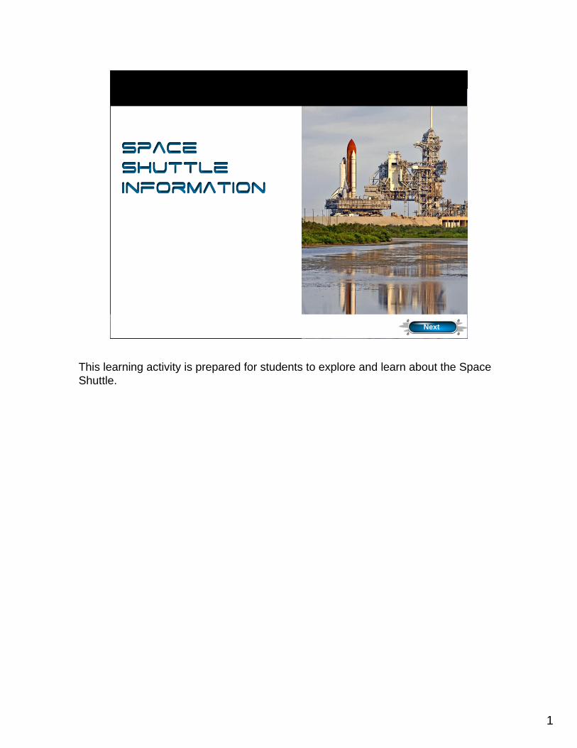
Space Shuttle Information
This learning activity is prepared for students to explore and learn about the Space Shuttle.
2
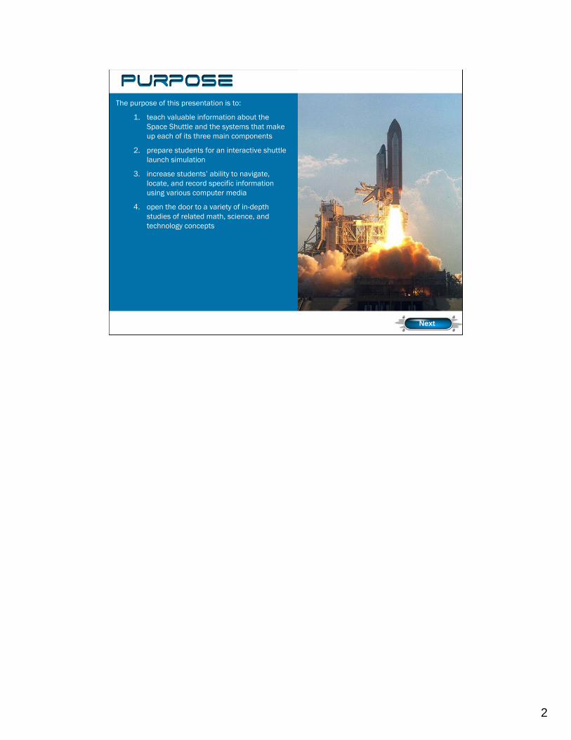
The purpose of this presentation is to:
1. teach valuable information about the Space Shuttle and the systems that make up each of its three main components
2. prepare students for an interactive shuttle launch simulation
3. increase students’ ability to navigate, locate, and record specific information using various computer media
4. open the door to a variety of in-depth studies of related math, science, and technology concepts
Next
Purpose
3
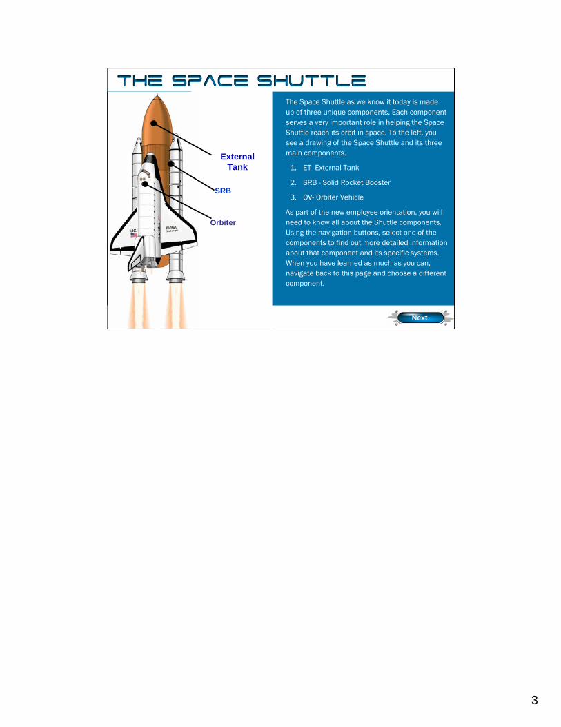
The Space Shuttle as we know it today is made up of three unique components. Each component serves a very important role in helping the Space Shuttle reach its orbit in space. To the left, you see a drawing of the Space Shuttle and its three main components.
1. ET- External Tank
2. SRB - Solid Rocket Booster
3. OV- Orbiter Vehicle
As part of the new employee orientation, you will need to know all about the Shuttle components. Using the navigation buttons, select one of the components to find out more detailed information about that component and its specific systems. When you have learned as much as you can, navigate back to this page and choose a different component.
SRB
External Tank
Orbiter
PurposeThe Space Shuttle
Next
The Space Shuttle as we know it today is made up of three unique components. Each component serves a very important role in helping the Space Shuttle reach its orbit in space. To the left, you see a drawing of the Space Shuttle and its three main components.
1. ET-External Tank
2. SRF-Solid Rocket Booster
3. OV-Orbiter Vehicle
As part of your new employee orientation, you will need to know all about the Shuttle components. Using the navigation buttons, select one of the components to find out more detailed information about that component and its specific systems. When you have learned as much as you can, navigate back to this page and choose a different component.
4
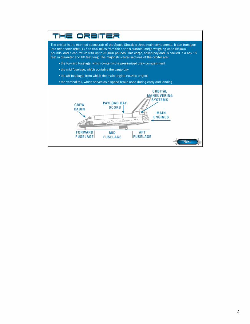
The orbiter is the manned spacecraft of the Space Shuttle’s three main components. It can transport into near earth orbit (115 to 690 miles from the earth’s surface) cargo weighing up to 56,000 pounds, and it can return with up to 32,000 pounds. This cargo, called payload, is carried in a bay 15 feet in diameter and 60 feet long. The major structural sections of the orbiter are:
•the forward fuselage, which contains the pressurized crew compartment
•the mid fuselage, which contains the cargo bay
•the aft fuselage, from which the main engine nozzles project
•the vertical tail, which serves as a speed brake used during entry and landing
Challenger Discovery Atlantis Endeavour
Next
The Orbiter
Next
The major structural sections of the orbiter are the forward fuselage, which contains the pressurized crew compartment; the mid fuselage, which contains the cargo bay; the aft fuselage, from which the main engine nozzles project; and the vertical tail, which splits open along the trailing edge to provide a speed brake used during entry and landing. The crew compartment is divided into two levels, the flight deck on top and the middeck below. The flight deck includes all flight controls used for launch, orbital trajectory corrections, rendezvous operations, and landing. The middeck middeck provides the crew's working, eating, and sleeping environment. It also houses the electronic, guidance, and navigation systems.
The orbiter normally carries a flight crew of four with three additional passengers. A total of 10 people could be carried under emergency conditions. The basic mission is seven days in space, but with additional supplies, a 30 day mission is possible.
5
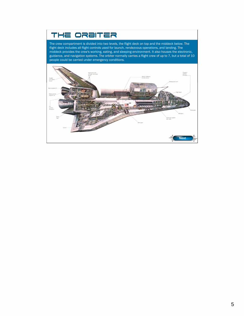
The crew compartment is divided into two levels, the flight deck on top and the middeck below. The flight deck includes all flight controls used for launch, rendezvous operations, and landing. The middeck provides the crew's working, eating, and sleeping environment. It also houses the electronic, guidance, and navigation systems. The orbiter normally carries a flight crew of up to 7, but a total of 10 people could be carried under emergency conditions.
Columbia Challenger Discovery Atlantis Endeavour
The Orbiter
Next
The crew compartment is divided into two levels, the flight deck on top and the middeck below. The flight deck includes all flight controls used for launch, orbital trajectory corrections, rendezvous operations, and landing. The middeck provides the crew's working, eating, and sleeping environment. It also houses the electronic, guidance, and navigation systems.
The orbiter normally carries a flight crew of four with three additional passengers. A total of 10 people could be carried under emergency conditions. The basic mission is seven days in space, but with additional supplies, a 30 day mission is possible.
6
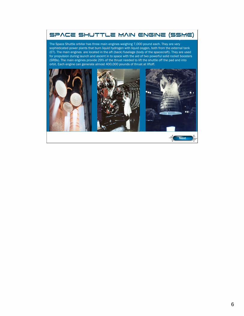
The Space Shuttle orbiter has three main engines weighing 7,000 pound each. They are very sophisticated power plants that burn liquid hydrogen with liquid oxygen, both from the external tank (ET). The main engines are located in the aft (back) fuselage (body of the spacecraft). They are used for propulsion during launch and ascent in to space with the aid of two powerful solid rocket boosters (SRBs). The main engines provide 29% of the thrust needed to lift the shuttle off the pad and into orbit. Each engine can generate almost 400,000 pounds of thrust at liftoff.
Main Engines
Next
The Space Shuttle orbiter has three main engines weighing 7,000 pound each. They are very sophisticated power plants that burn liquid hydrogen with liquid oxygen, both from the external tank (ET). The main engines are located in the aft (back) fuselage (body of the spacecraft). They are used for propulsion during launch and ascent in to space with the aid of two powerful solidrocket boosters (SRBs). The main engines provide 29% of the thrust needed to lift the shuttle off the pad and into orbit. Each engine can generate almost 400,000 pounds of thrust at liftoff.
7
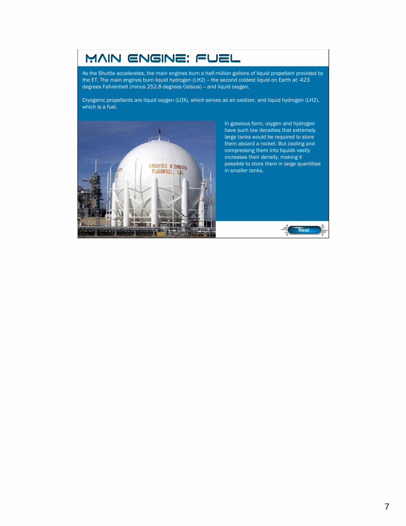
As the Shuttle accelerates, the main engines burn a half-million gallons of liquid propellant provided by the ET. The main engines burn liquid hydrogen (LH2) -- the second coldest liquid on Earth at -423 degrees Fahrenheit (minus 252.8 degrees Celsius) -- and liquid oxygen.
Cryogenic propellants are liquid oxygen (LOX), which serves as an oxidizer, and liquid hydrogen (LH2), which is a fuel.
Fuel
In gaseous form, oxygen and hydrogen have such low densities that extremely large tanks would be required to store them aboard a rocket. But cooling and compressing them into liquids vastly increases their density, making it possible to store them in large quantities in smaller tanks.
Next
As the Shuttle accelerates, the main engines burn a half-million gallons of liquid propellant provided by the ET. The main engines burn liquid hydrogen (LH2) -- the second coldest liquid on Earth at -423 degrees Fahrenheit (minus 252.8 degrees Celsius) -- and liquid oxygen.
Cryogenic propellants are liquid oxygen (LOX), which serves as an oxidizer, and liquid hydrogen (LH2), which is a fuel.
In gaseous form, oxygen and hydrogen have such low densities that extremely large tanks would be required to store them aboard a rocket. But cooling and compressing them into liquids vastly increases their density, making it possible to store them in large quantities in smaller tanks.
8
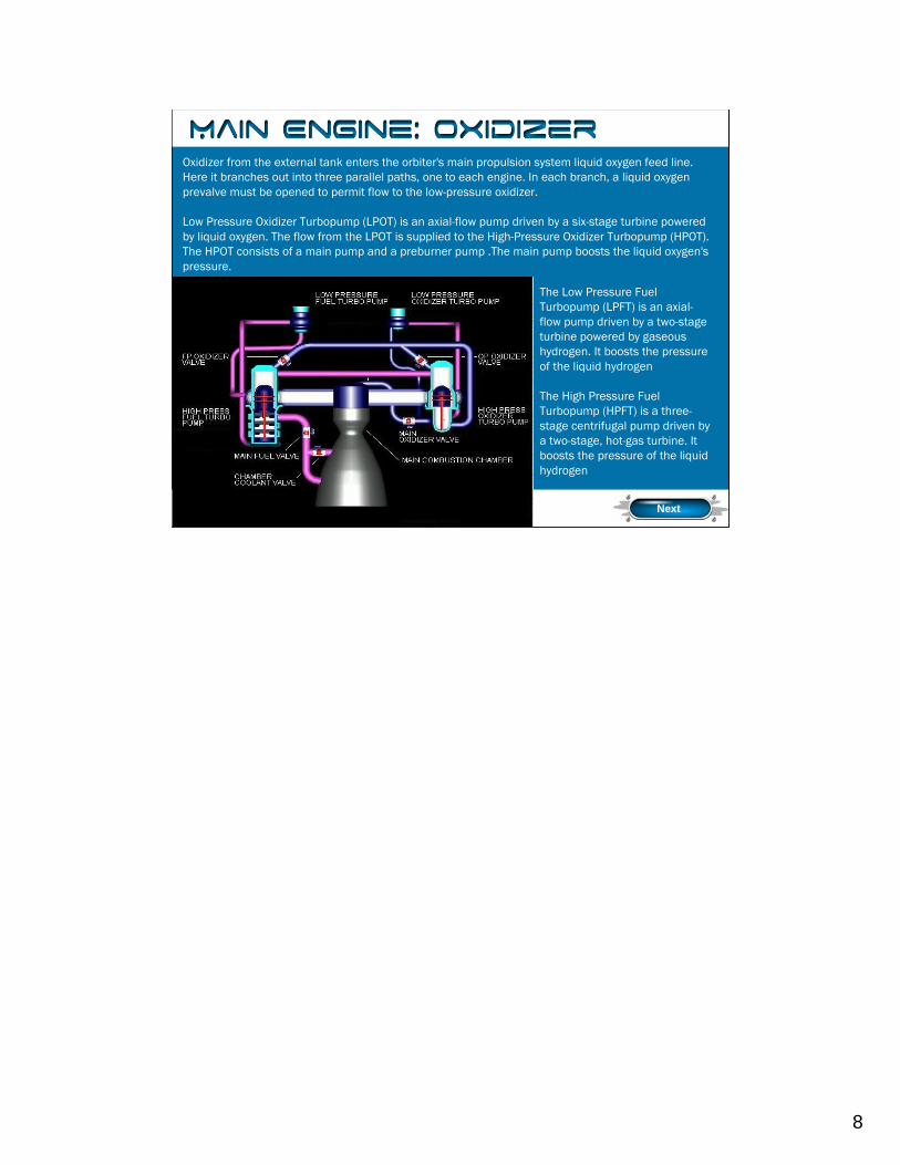
Oxidizer from the external tank enters the orbiter's main propulsion system liquid oxygen feed line. Here it branches out into three parallel paths, one to each engine. In each branch, a liquid oxygen prevalve must be opened to permit flow to the low-pressure oxidizer.
Low Pressure Oxidizer Turbopump (LPOT) is an axial-flow pump driven by a six-stage turbine powered by liquid oxygen. The flow from the LPOT is supplied to the High-Pressure Oxidizer Turbopump (HPOT). The HPOT consists of a main pump and a preburner pump .The main pump boosts the liquid oxygen's pressure.
Oxidizer
The Low Pressure Fuel Turbopump (LPFT) is an axial-flow pump driven by a two-stage turbine powered by gaseous hydrogen. It boosts the pressure of the liquid hydrogen
The High Pressure Fuel Turbopump (HPFT) is a three-stage centrifugal pump driven by a two-stage, hot-gas turbine. It boosts the pressure of the liquid hydrogen
Next
Oxidizer from the external tank enters the orbiter's main propulsion system liquid oxygen feed line. Here it branches out into three parallel paths, one to each engine. In each branch, a liquid oxygen prevalve must be opened to permit flow to the low-pressure oxidizer.
The Low Pressure Oxidizer Turbopump (LPOT) is an axial-flow pump driven by a six-stage turbine powered by liquid oxygen. It boosts the liquid oxygen's pressure from 100 to 422 psia (pounds per square inch (actual)). The flow from the LPOT is supplied to the High-Pressure Oxidizer Turbopump (HPOT). During engine operation, the pressure boost permits the High Pressure Oxidizer Turbine to operate at high speeds without cavitating. The LPOT operates at approximately 5,150 rpm. The HPOT consists of two single-stage centrifugal pumps (a main pump and a preburner pump) mounted on a common shaft and driven by a two-stage, hot-gas turbine. The main pump boosts the liquid oxygen's pressure from 422 to 4,300 psia while operating at approximately 28,120 rpm. The HPOT discharge flow splits into several paths, one of which is routed to drive the LPOT turbine. Another path is routed to and through the main oxidizer valve and enters into the main combustion chamber. Another small flow path is tapped off and sent to theoxidizer.
Fuel enters the orbiter at the liquid hydrogen feed line disconnect valve, then flows into the orbiter’s gaseous hydrogen feed line manifold. Here the feed line branches out into three parallel paths to each engine. In each liquid hydrogen branch, a prevalve permits liquid hydrogen to flow to the low-pressure fuel turbopump when the prevalve is open.
The Low Pressure Fuel Turbopump (LPFT) is an axial-flow pump driven by a two-stage turbine powered by gaseous hydrogen. It boosts the pressure of the liquid hydrogen from 30 to 276 psia and supplies it to the High-Pressure Fuel Turbopump (HPFT). D i g gi ti th b t id d b th LPFT it th HPFT t
9
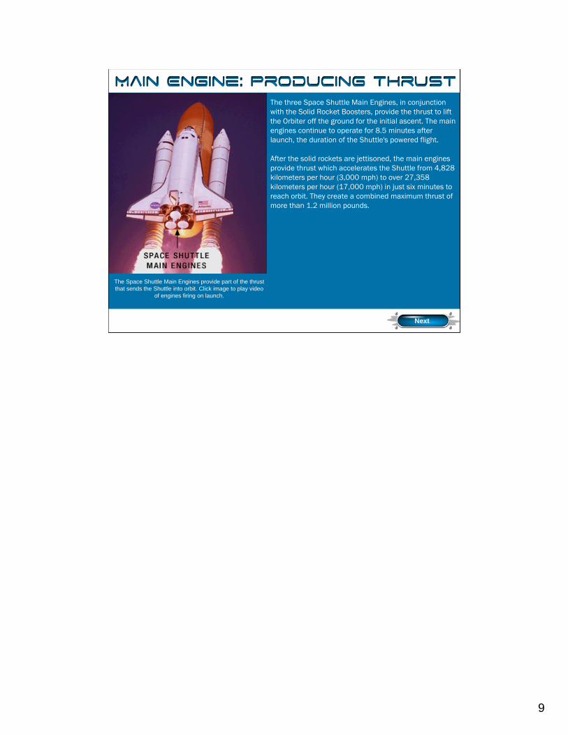
The three Space Shuttle Main Engines, in conjunction with the Solid Rocket Boosters, provide the thrust to lift the Orbiter off the ground for the initial ascent. The main engines continue to operate for 8.5 minutes after launch, the duration of the Shuttle's powered flight.
After the solid rockets are jettisoned, the main engines provide thrust which accelerates the Shuttle from 4,828 kilometers per hour (3,000 mph) to over 27,358 kilometers per hour (17,000 mph) in just six minutes to reach orbit. They create a combined maximum thrust of more than 1.2 million pounds.
Thrust
The Space Shuttle Main Engines provide part of the thrust that sends the Shuttle into orbit. Click image to play video
of engines firing on launch.
Next
The fuel and oxidizer enter the preburners and are mixed so that efficient combustion can occur. The augmented spark igniter is a small combination chamber located in the center of the injector of each preburner. The two dual-redundant spark igniters, which are activated by the engine controller, are used during the engine start sequence to initiate combustion in each preburner. They are turned off after approximately three seconds because the combustion process is then self-sustaining. The preburners produce the fuel-rich hot gas that passes through the turbines to generate the power to operate the high-pressure turbopumps. The oxidizer preburner's outflow drives a turbine that is connected to the HPOT and the oxidizer preburner pump. The fuel preburner's outflow drives a turbine that is connected to the HPFT.
The HPOT turbine and HPOT pumps are mounted on a common shaft. Mixing of the fuel-rich hot gas in the turbine section and the liquid oxygen in the main pump could create a hazard. To prevent this, the two sections are separated by a cavity that is continuously purged by the MPS (Main Propulsion System) engine helium supply during engine operation. Two seals minimize leakage into the cavity. Loss of helium pressure in this cavity results in an automatic engine shutdown.
The speed of the HPOT and HPFT turbines depends on the position of the corresponding oxidizer and fuel preburner oxidizer valves. These valves are positioned by the engine controller, which uses them to throttle the flow of liquid oxygen to the preburners and, thus, control engine thrust. The oxidizer and fuel preburner oxidizer valves increase or decrease the liquid oxygen flow. This then causes increasing or decreasing preburner chamber pressure, HPOT and HPFT turbine speed, and liquid oxygen and gaseous hydrogen flow into the main combustion chamber. When this happens, it increases or decreases engine thrust, thus throttling the engine. The oxidizer and fuel preburner valves operate together to throttle the engine and maintain
t t 6 1 ll t i t ti Th i idi l d th i f l l
10
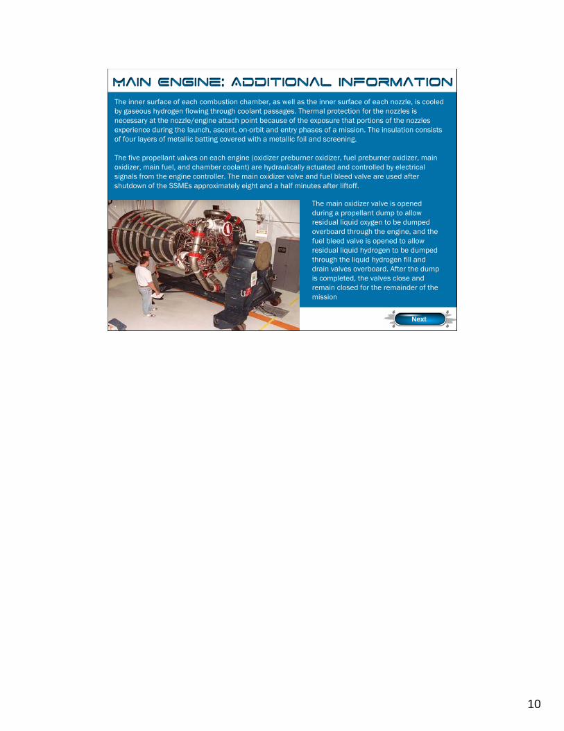
The inner surface of each combustion chamber, as well as the inner surface of each nozzle, is cooled by gaseous hydrogen flowing through coolant passages. Thermal protection for the nozzles is necessary at the nozzle/engine attach point because of the exposure that portions of the nozzles experience during the launch, ascent, on-orbit and entry phases of a mission. The insulation consists of four layers of metallic batting covered with a metallic foil and screening.
The five propellant valves on each engine (oxidizer preburner oxidizer, fuel preburner oxidizer, main oxidizer, main fuel, and chamber coolant) are hydraulically actuated and controlled by electrical signals from the engine controller. The main oxidizer valve and fuel bleed valve are used after shutdown of the SSMEs approximately eight and a half minutes after liftoff.
.
Additional Info
The main oxidizer valve is opened during a propellant dump to allow residual liquid oxygen to be dumped overboard through the engine, and the fuel bleed valve is opened to allow residual liquid hydrogen to be dumped through the liquid hydrogen fill and drain valves overboard. After the dump is completed, the valves close and remain closed for the remainder of the mission
Next
The inner surface of each combustion chamber, as well as the inner surface of each nozzle, is cooled by gaseous hydrogen flowing through coolant passages. The nozzle assembly is a bell-shaped extension bolted to the main combustion chamber. The nozzle is 113 inches (2.9 m) long, and the outside diameter of the exit is 94 inches (2.4 m). Thermal protection for the nozzles is necessary at the nozzle/engine attach point because of the exposure that portions of the nozzles experience during the launch, ascent, on-orbit and entry phases of a mission. The insulation consists of four layers of metallic batting covered with a metallic foil and screening (part of the orbiter’s heat shield).
The five propellant valves on each engine (oxidizer preburner oxidizer, fuel preburner oxidizer, main oxidizer, main fuel, and chamber coolant) are hydraulically actuated and controlled by electrical signals from the engine controller. They can be fully closed by using the MPS engine helium supply system as a backup actuation system. The main oxidizer valve and fuel bleed valve are used after shutdown off the SSMEs approximately eight and a half minutes after liftoff.
The main oxidizer valve is opened during a propellant dump to allow residual liquid oxygen to be dumped overboard through the engine, and the fuel bleed valve is opened to allow residual liquid hydrogen to be dumped through the liquid hydrogen fill and drain valves overboard. After the dump is completed, the valves close and remain closed for the remainder of the mission.
11
OMS
Watch Video
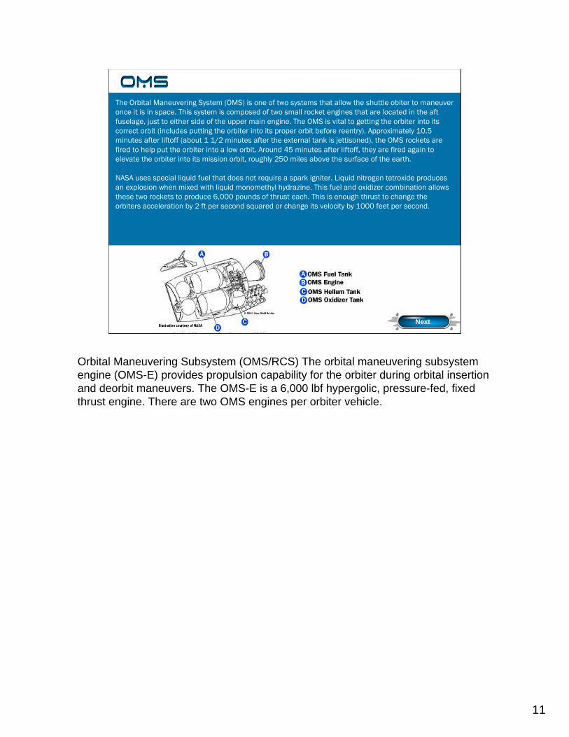
The Orbital Maneuvering System (OMS) is one of two systems that allow the shuttle obiter to maneuver once it is in space. This system is composed of two small rocket engines that are located in the aft fuselage, just to either side of the upper main engine. The OMS is vital to getting the orbiter into its correct orbit (includes putting the orbiter into its proper orbit before reentry). Approximately 10.5 minutes after liftoff (about 1 1/2 minutes after the external tank is jettisoned), the OMS rockets are fired to help put the orbiter into a low orbit. Around 45 minutes after liftoff, they are fired again to elevate the orbiter into its mission orbit, roughly 250 miles above the surface of the earth.
NASA uses special liquid fuel that does not require a spark igniter. Liquid nitrogen tetroxide produces an explosion when mixed with liquid monomethyl hydrazine. This fuel and oxidizer combination allows these two rockets to produce 6,000 pounds of thrust each. This is enough thrust to change the orbiters acceleration by 2 ft per second squared or change its velocity by 1000 feet per second.
Next
Orbital Maneuvering Subsystem (OMS/RCS) The orbital maneuvering subsystem engine (OMS-E) provides propulsion capability for the orbiter during orbital insertion and deorbit maneuvers. The OMS-E is a 6,000 lbf hypergolic, pressure-fed, fixed thrust engine. There are two OMS engines per orbiter vehicle.
The Orbital Maneuvering System (OMS) is one of two systems that allow the shuttle obiter to maneuver once it is in space. This system is composed of two small rocket engines that are located in the aft fuselage, just to either side of the upper main engine. The OMS is vital to getting the orbiter into its correct orbit (includes putting the orbiter into its proper orbit before reentry). Approximately 10.5 minutes after liftoff (about one and a half minutes after the external tank is jettisoned), the OMS rockets are fired to help put the orbiter into a low orbit. Around 45 minutes after liftoff, they are fired again to elevate the orbiter into its mission orbit, roughly 250 miles above the surface of the earth.
To help reduce weight and minimize on space, NASA uses special liquid fuel that does not require a spark igniter. Liquid nitrogen tetroxide produces an explosion when mixed with liquid monomethyl hydrazine., along with similar engines, had been proven successful in other space vehicles, especially the Apollo rockets. Though these two rockets may be smaller than their Apollo counterparts, they still are able to produce 6,000 pounds of thrust each. This is enough thrust to change the orbiters acceleration by two feet per second squared or change its velocity by 1000 feet per second.
The nitrogen tetroxide and monomethyl hydrazine are stored in two separate containers in the shuttle that are pressurized by helium. By using helium to pressurize the tanks, NASA is able to eliminate having to use a mechanical pump to remove the liquids from their storage containers. To control the amount of liquid being released from each
12
OMSRCS
(Just off picture)
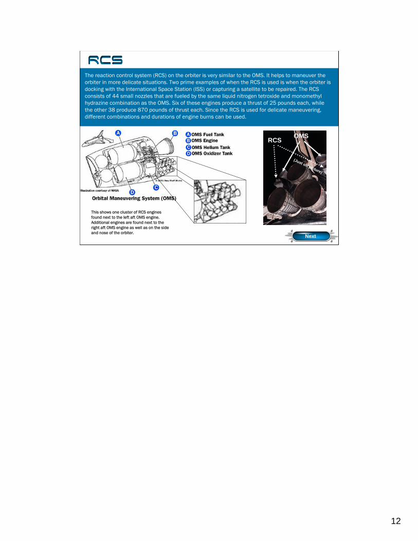
This shows one cluster of RCS engines found next to the left aft OMS engine. Additional engines are found next to the right aft OMS engine as well as on the side and nose of the orbiter.
The reaction control system (RCS) on the orbiter is very similar to the OMS. It helps to maneuver the orbiter in more delicate situations. Two prime examples of when the RCS is used is when the orbiter is docking with the International Space Station (ISS) or capturing a satellite to be repaired. The RCS consists of 44 small nozzles that are fueled by the same liquid nitrogen tetroxide and monomethylhydrazine combination as the OMS. Six of these engines produce a thrust of 25 pounds each, while the other 38 produce 870 pounds of thrust each. Since the RCS is used for delicate maneuvering, different combinations and durations of engine burns can be used.
RCS
Next
The reaction control system (RCS) on the orbiter is very similar to the OMS; however, the RCS is important for helping maneuver the orbiter in more delicate situations. Two prime examples of when the RCS is used is when the orbiter is docking with the International Space Station (ISS) or capturing a satellite to be repaired.
The RCS consists of 44 small nozzles that are fueled by the same liquid nitrogen tetroxide and monomethyl hydrazine combination as the OMS. These nozzles are found on either side of the orbiter’s nose or aft fuselage. Six of these engines produce a thrust of 25 pounds each, while the other 38 produce 870 pounds of thrust each. Since the RCS is used for delicate maneuvering, different combinations and durations of engine burns from the RCS can be used.
13
ECLSS: Four Main Sub-Systems
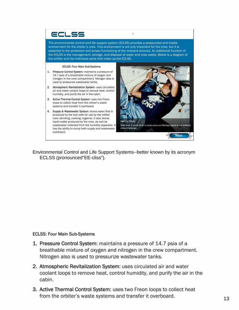
1. Pressure Control System: maintains a pressure of 14.7 psia of a breathable mixture of oxygen and nitrogen in the crew compartment. Nitrogen also is used to pressurize wastewater tanks.
2. Atmospheric Revitalization System: uses circulated air and water coolant loops to remove heat, control humidity, and purify the air in the cabin.
3. Active Thermal Control System: uses two Freon loops to collect heat from the orbiter’s waste systems and transfer it overboard.
4. Supply & Wastewater System: stores water that is produced by the fuel cells for use by the orbiter crew (drinking, cooking, hygiene). It also stores liquid waste produced by the crew, as well as wastewater collected from the humidity separator. It has the ability to dump both supply and wastewater overboard.
The environmental control and life support system (ECLSS) provides a pressurized and livable environment for the orbiter’s crew. This environment is not only important for the crew, but it is essential to the protection and proper functioning of the onboard avionics. An additional function of the ECLSS is the management, storage, and disposal of water and crew waste. Below is a diagram of the orbiter and the individual parts that make up the ECLSS.
ECLSS
Next
Environmental Control and Life Support Systems--better known by its acronym ECLSS (pronounced"EE-cliss").
The environmental control and life support system (ECLSS) provides a pressurized and livable environment for the orbiter’s crew. This environment is not only important for the crew, but it is essential to the protection and proper functioning of the onboard avionics. An additional function of the ECLSS is the management, storage, and disposal of water and crew waste. Below and to the left is a diagram of the orbiter and the individual parts that make up the ECLSS.
ECLSS: Four Main Sub-Systems
1. Pressure Control System: maintains a pressure of 14.7 psia of a breathable mixture of oxygen and nitrogen in the crew compartment. Nitrogen also is used to pressurize wastewater tanks.
2. Atmospheric Revitalization System: uses circulated air and water coolant loops to remove heat, control humidity, and purify the air in the cabin.
3. Active Thermal Control System: uses two Freon loops to collect heat from the orbiter’s waste systems and transfer it overboard.
14
Click to visit “How Stuff Works” website to get additional information on how solid rockets work.
Click to see how the Shuttle SRB operates.
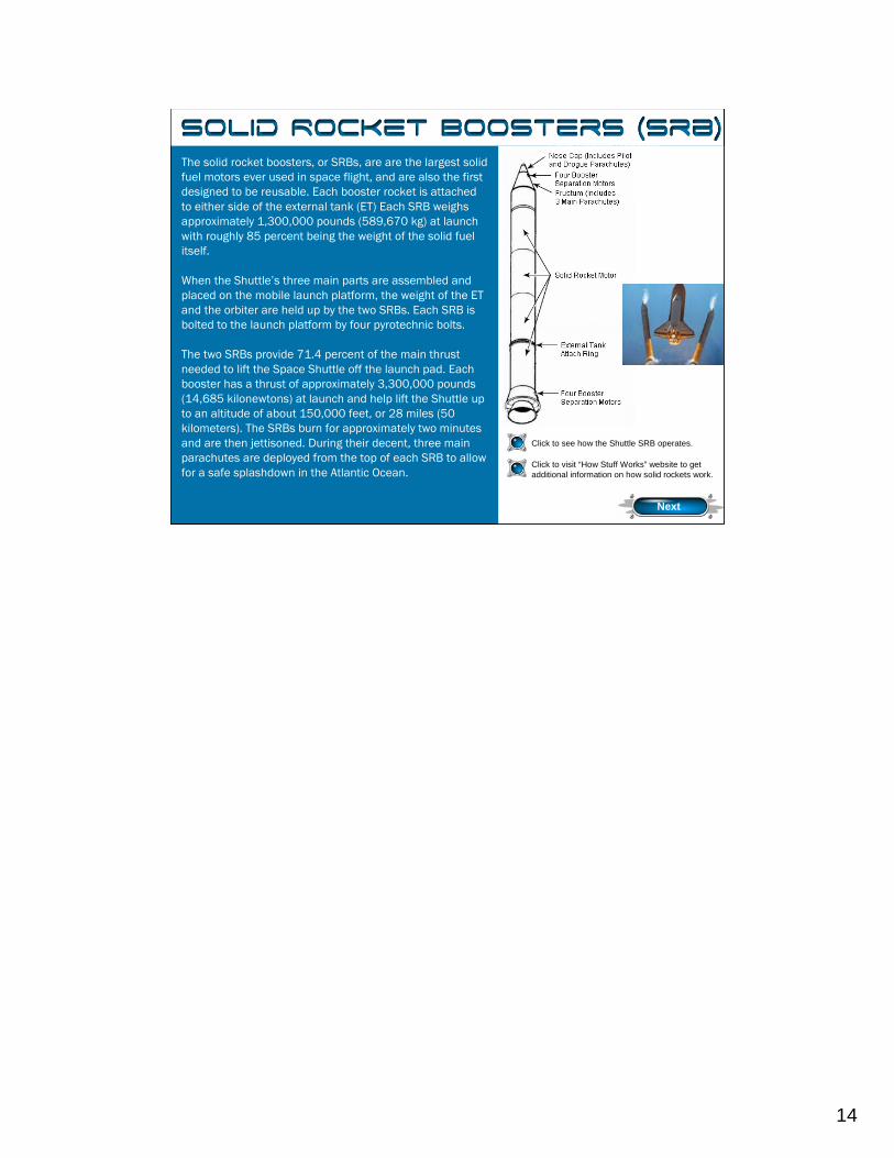
The solid rocket boosters, or SRBs, are are the largest solid fuel motors ever used in space flight, and are also the first designed to be reusable. Each booster rocket is attached to either side of the external tank (ET) Each SRB weighs approximately 1,300,000 pounds (589,670 kg) at launch with roughly 85 percent being the weight of the solid fuel itself.
When the Shuttle’s three main parts are assembled and placed on the mobile launch platform, the weight of the ET and the orbiter are held up by the two SRBs. Each SRB is bolted to the launch platform by four pyrotechnic bolts.
The two SRBs provide 71.4 percent of the main thrust needed to lift the Space Shuttle off the launch pad. Each booster has a thrust of approximately 3,300,000 pounds (14,685 kilonewtons) at launch and help lift the Shuttle up to an altitude of about 150,000 feet, or 28 miles (50 kilometers). The SRBs burn for approximately two minutes and are then jettisoned. During their decent, three main parachutes are deployed from the top of each SRB to allow for a safe splashdown in the Atlantic Ocean.
Next
Solid Rocket Boosters
The solid rocket boosters, or SRBs, are one of the three main parts of the shuttle system (SRBs, external tank, orbiter). These booster rockets are the largest solid fuel motors ever used in space flight, and are also the first designed to be reusable. Each booster rocket is attached to either side of the external tank (ET) and is 149.16 feet (45.46 meters) tall with a diameter of 12.17 feet (3.7 meters). Each SRB weighs approximately 1,300,000 pounds (589,670 kilograms) at launch with roughly 85 percent being the weight of the solid fuel itself (The solid fuel, or propellant, is a mixture of ammonium perchlorate, aluminum, and iron oxide.).
When the Shuttle’s three main parts are assembled and placed on the mobile launchplatform, the weight of the ET and the orbiter are held up by the two SRBs. Each SRB is bolted to the launch platform by four pyrotechnic bolts; each bolt is 28 inches long and is 3.5 inches in diameter. These bolts are design to: 1) support the Shuttle while on the launch platform (including holding it while on its transported three mile to one of the two launching complexes), 2) hold the Shuttle down while the Shuttle’s three main engines ignite at T-6 seconds in the countdown, and 3) pyrotechnically break when the SRBs are ignited at T-0 seconds.
The two SRBs provide 71.4 percent of the main thrust needed to lift the Space Shuttle off the launch pad. Each booster has a thrust of approximately 3,300,000 pounds (14,685 kilonewtons) at launch and help lift the Shuttle up to an altitude of about150,000 feet, or 28 miles (50 kilometers). The SRBs burn for approximately two minutes and are then jettisoned. During their decent, three main parachutes are deployed from the top of each SRB to allow for a safe splashdown in the Atlantic Ocean, roughly 141 miles (260 kilometers) downrange from Kennedy Space Center.
15
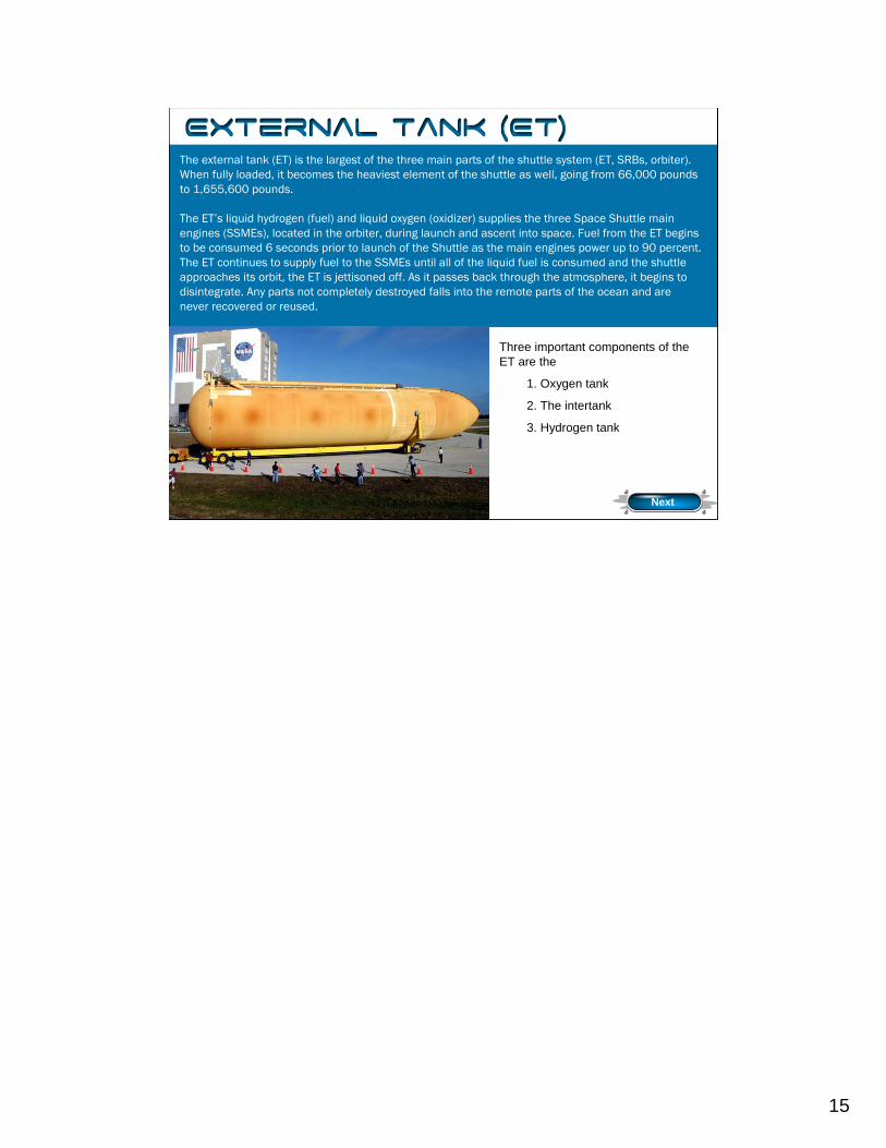
Three important components of the ET are the
1. Oxygen tank
2. The intertank
3. Hydrogen tank
The external tank (ET) is the largest of the three main parts of the shuttle system (ET, SRBs, orbiter). When fully loaded, it becomes the heaviest element of the shuttle as well, going from 66,000 pounds to 1,655,600 pounds.
The ET’s liquid hydrogen (fuel) and liquid oxygen (oxidizer) supplies the three Space Shuttle main engines (SSMEs), located in the orbiter, during launch and ascent into space. Fuel from the ET begins to be consumed 6 seconds prior to launch of the Shuttle as the main engines power up to 90 percent. The ET continues to supply fuel to the SSMEs until all of the liquid fuel is consumed and the shuttle approaches its orbit, the ET is jettisoned off. As it passes back through the atmosphere, it begins to disintegrate. Any parts not completely destroyed falls into the remote parts of the ocean and are never recovered or reused.
External Tank
Next
The external tank (ET) is the largest of the three main parts of the shuttle system (ET, SRBs, orbiter). When fully loaded, it becomes the heaviest element of the shuttle as well, going from 66,000 pounds to 1,655,600 pounds. The 153.8 feet (47 meters) tall ET has a diameter of 27.6 feet (8.4 meters). It is divided into three major components: 1) liquid oxygen tank, 2) intertank, and 3) liquid hydrogen tank.
The ET’s liquid hydrogen (fuel) and liquid oxygen (oxidizer) supplies the three Space Shuttle main engines (SSMEs), located in the orbiter, during launch and ascent into space. Fuel from the ET begins to be consumed 6 seconds prior to launch of the Shuttle as the main engines power up to 90 percent. After two minutes of the ascent into orbit, the shuttle’s SRBs are jettisoned from the ET and descend into the Atlantic Ocean to be captured and reused. The ET continues to supply fuel to the SSMEs for approximately another six and a half minutes. When all of the liquid fuel is consumed and the shuttle approaches its orbit, the ET is jettisoned off. As it passes back through the atmosphere, it begins to disintegrate. Any parts not completely destroyed fallsinto the remote parts of the ocean and are never recovered or
16
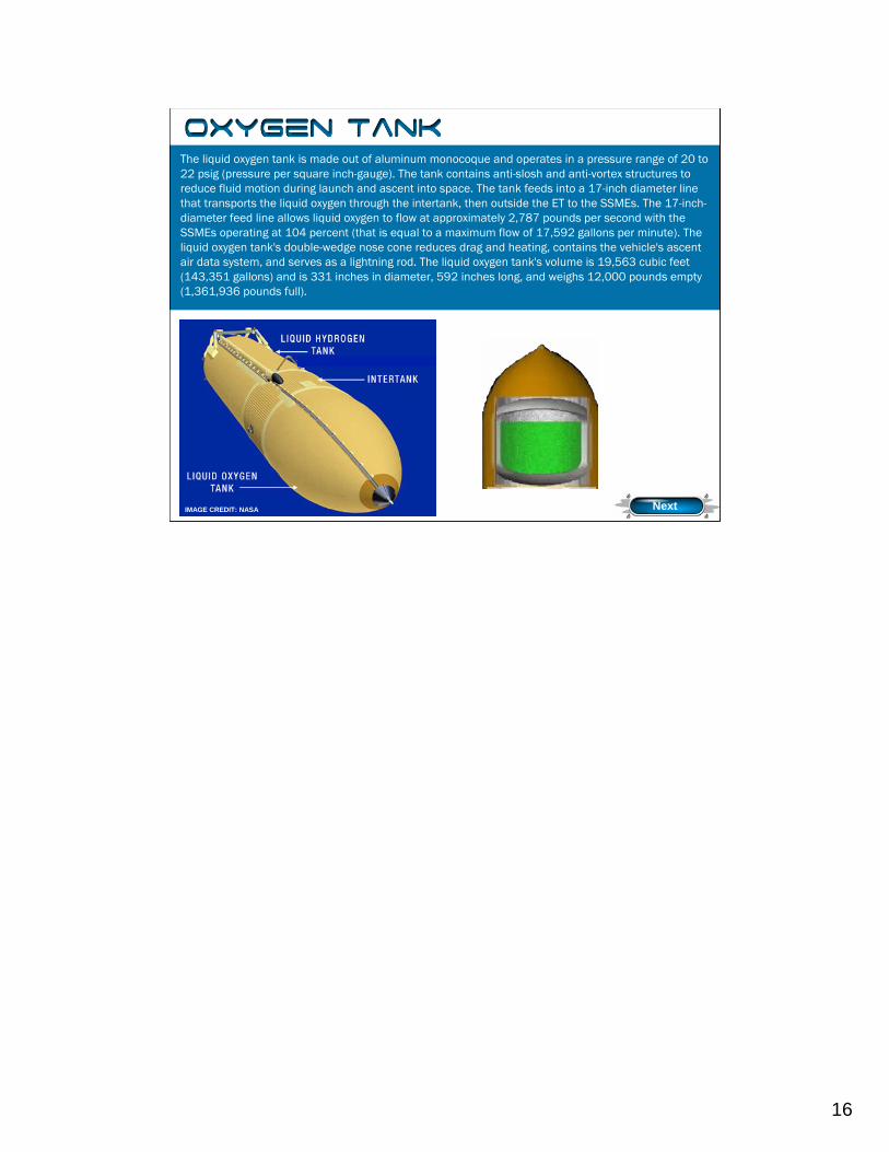
The liquid oxygen tank is made out of aluminum monocoque and operates in a pressure range of 20 to 22 psig (pressure per square inch-gauge). The tank contains anti-slosh and anti-vortex structures to reduce fluid motion during launch and ascent into space. The tank feeds into a 17-inch diameter line that transports the liquid oxygen through the intertank, then outside the ET to the SSMEs. The 17-inch-diameter feed line allows liquid oxygen to flow at approximately 2,787 pounds per second with the SSMEs operating at 104 percent (that is equal to a maximum flow of 17,592 gallons per minute). The liquid oxygen tank's double-wedge nose cone reduces drag and heating, contains the vehicle's ascent air data system, and serves as a lightning rod. The liquid oxygen tank's volume is 19,563 cubic feet (143,351 gallons) and is 331 inches in diameter, 592 inches long, and weighs 12,000 pounds empty (1,361,936 pounds full).
IMAGE CREDIT: NASA
Oxygen Tank
Next
17
Intertank
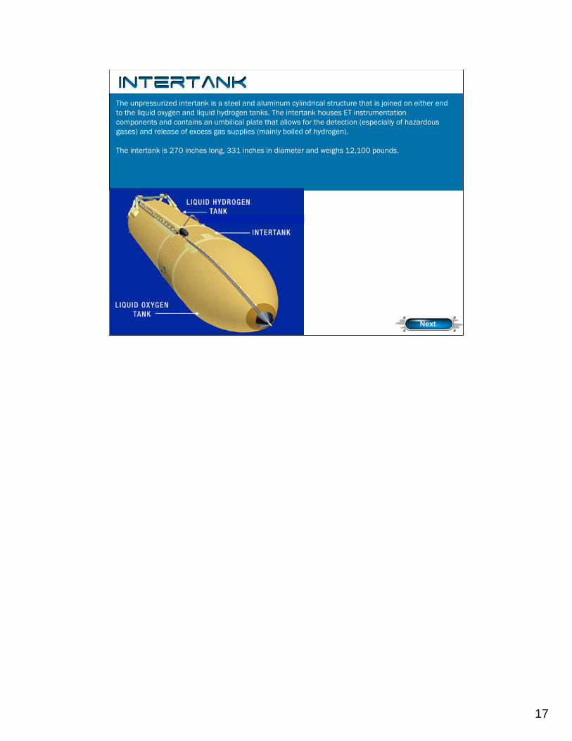
The unpressurized intertank is a steel and aluminum cylindrical structure that is joined on either end to the liquid oxygen and liquid hydrogen tanks. The intertank houses ET instrumentation components and contains an umbilical plate that allows for the detection (especially of hazardous gases) and release of excess gas supplies (mainly boiled of hydrogen).
The intertank is 270 inches long, 331 inches in diameter and weighs 12,100 pounds.
Next
18
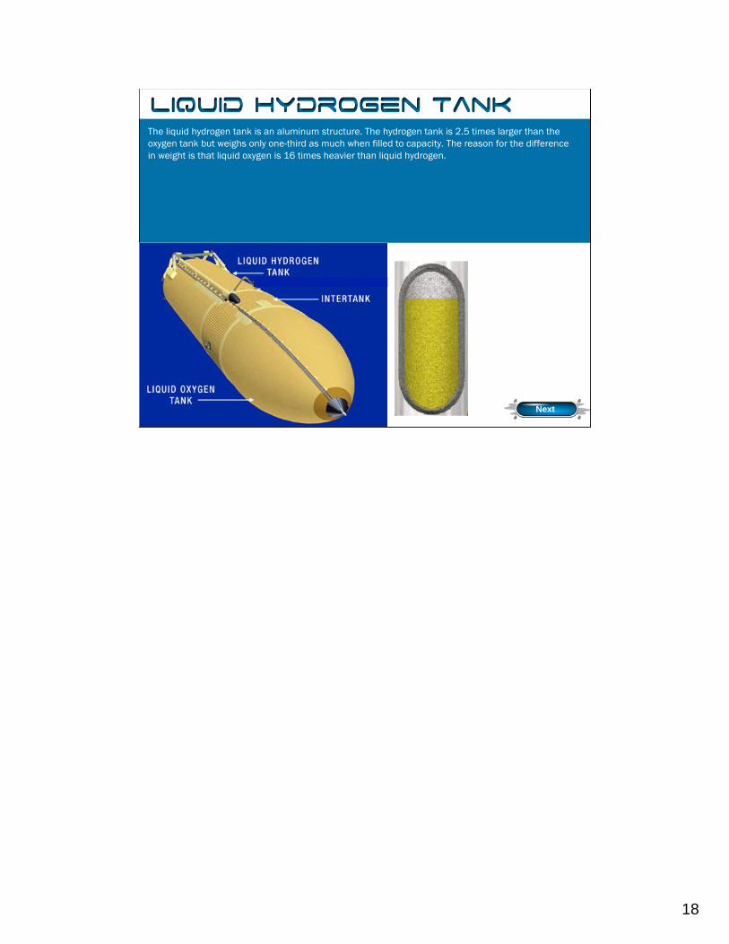
The liquid hydrogen tank is an aluminum structure. The hydrogen tank is 2.5 times larger than the oxygen tank but weighs only one-third as much when filled to capacity. The reason for the difference in weight is that liquid oxygen is 16 times heavier than liquid hydrogen.
Liquid Hydrogen Tank
Next
The liquid hydrogen tank is an aluminum semimonocoque structure with an operating pressure range of 32 to 34 psia (pounds per square inch-absolute). The tank contains an anti-vortex baffle and siphon outlet to transport the liquid hydrogenfrom the tank through a 17-inch line. The liquid hydrogen feed line flow rate is 465 pounds per second with the SSMEs at 104 percent (has a maximum flow of 47,365 gallons per minute). The liquid hydrogen tank is 331 inches in diameter, 1,160 inches long, and has a volume of 53,518 cubic feet (385,265 gallons). It has a dry weight of 29,000 pounds (227,641 pounds full).
19
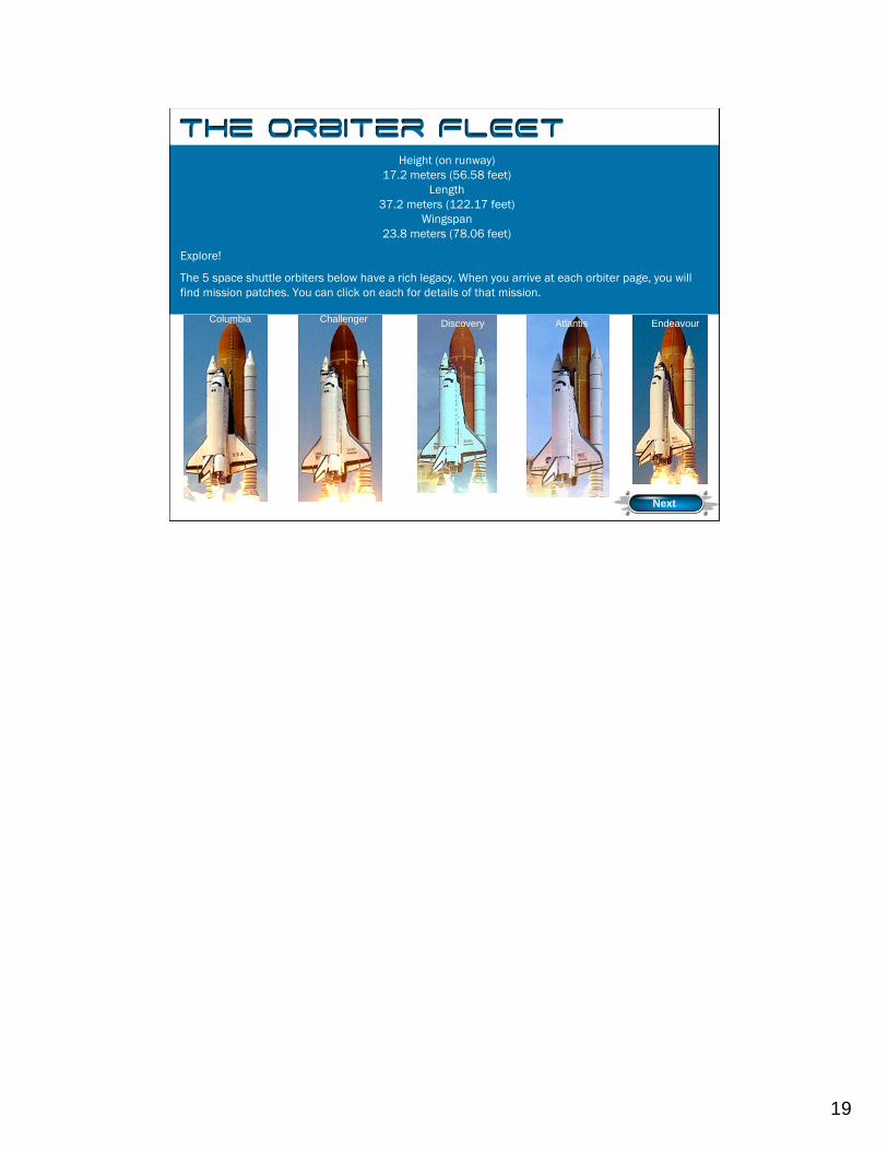
Height (on runway)17.2 meters (56.58 feet)
Length37.2 meters (122.17 feet)
Wingspan23.8 meters (78.06 feet)
Explore!
The 5 space shuttle orbiters below have a rich legacy. When you arrive at each orbiter page, you will find mission patches. You can click on each for details of that mission.
Columbia Challenger Discovery Atlantis Endeavour
Next
The Orbiter Fleet
The Space Shuttle Orbiter fleet. Discovery, Atlantis and Endeavour are still active.
Explore!
Click on each picture below to find out statistics on that particular orbiter. When you arrive at each orbiter page, you will find mission patches. You can click on each for details of that mission.
20
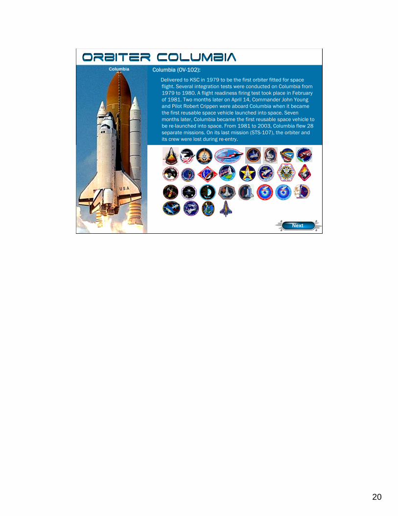
Columbia (OV-102):
Delivered to KSC in 1979 to be the first orbiter fitted for space flight. Several integration tests were conducted on Columbia from 1979 to 1980. A flight readiness firing test took place in February of 1981. Two months later on April 14, Commander John Young and Pilot Robert Crippen were aboard Columbia when it became the first reusable space vehicle launched into space. Seven months later, Columbia became the first reusable space vehicle to be re-launched into space. From 1981 to 2003, Columbia flew 28 separate missions. On its last mission (STS-107), the orbiter and its crew were lost during re-entry.
Columbia
Orbiter Columbia
Next
21
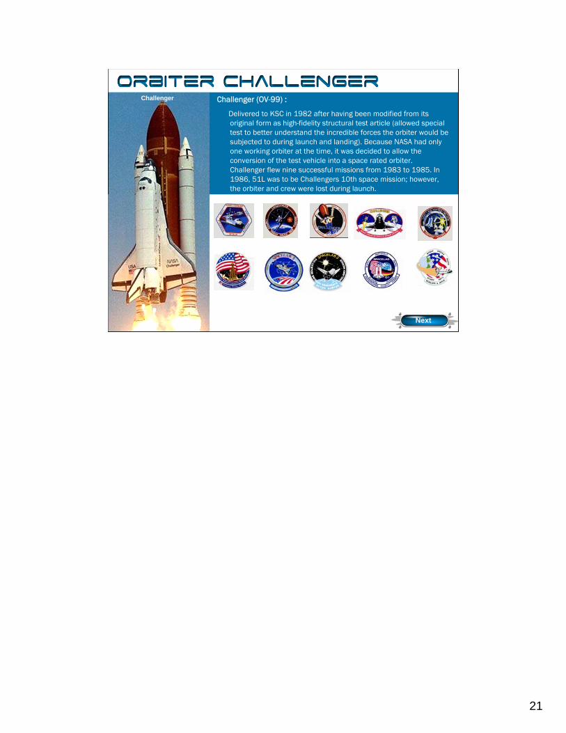
Challenger (OV-99) :
Delivered to KSC in 1982 after having been modified from its original form as high-fidelity structural test article (allowed special test to better understand the incredible forces the orbiter would be subjected to during launch and landing). Because NASA had only one working orbiter at the time, it was decided to allow the conversion of the test vehicle into a space rated orbiter. Challenger flew nine successful missions from 1983 to 1985. In 1986, 51L was to be Challengers 10th space mission; however, the orbiter and crew were lost during launch.
Challenger
Orbiter Challenger
Next
22
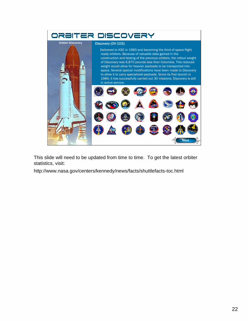
Discovery (OV-103):
Delivered to KSC in 1983 and becoming the third of space flight ready orbiters. Because of valuable data gained in the construction and testing of the previous orbiters, the rollout weight of Discovery was 6,870 pounds less then Columbia. This reduced weight would allow for heavier payloads to be transported into space. Several special modifications have been made to Discoveryto allow it to carry specialized payloads. Since its first launch in 1984, it has successfully carried out 30 missions. Discovery is still in active service.
Discovery
Orbiter Discovery
Next
This slide will need to be updated from time to time. To get the latest orbiter statistics, visit:http://www.nasa.gov/centers/kennedy/news/facts/shuttlefacts-toc.html
23
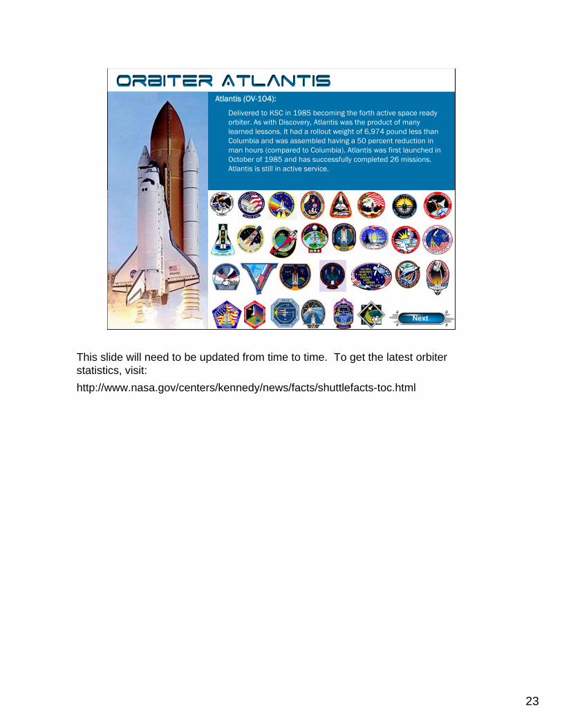
Atlantis (OV-104):
Delivered to KSC in 1985 becoming the forth active space ready orbiter. As with Discovery, Atlantis was the product of many learned lessons. It had a rollout weight of 6,974 pound less than Columbia and was assembled having a 50 percent reduction in man hours (compared to Columbia). Atlantis was first launched inOctober of 1985 and has successfully completed 26 missions. Atlantis is still in active service.
Atlantis
Orbiter Atlantis
Next
This slide will need to be updated from time to time. To get the latest orbiter statistics, visit:http://www.nasa.gov/centers/kennedy/news/facts/shuttlefacts-toc.html
24
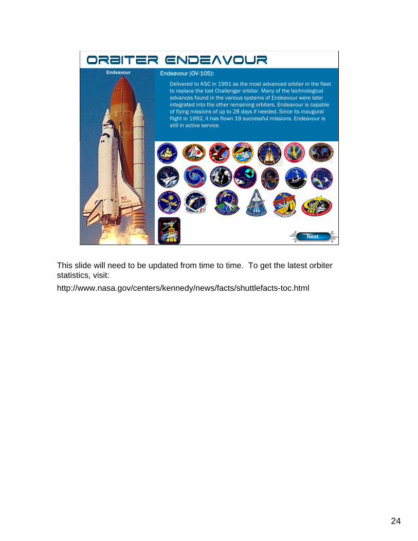
Endeavour (OV-105):
Delivered to KSC in 1991 as the most advanced orbiter in the fleet to replace the lost Challenger orbiter. Many of the technological advances found in the various systems of Endeavour were later integrated into the other remaining orbiters. Endeavour is capable of flying missions of up to 28 days if needed. Since its inaugural flight in 1992, it has flown 19 successful missions. Endeavour is still in active service.
Endeavour
Orbiter Endeavour
Next
This slide will need to be updated from time to time. To get the latest orbiter statistics, visit:http://www.nasa.gov/centers/kennedy/news/facts/shuttlefacts-toc.html
25
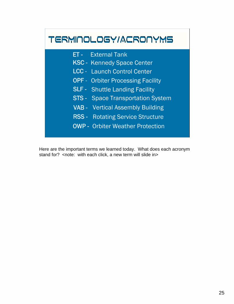
Terminology/Acronyms
External TankKennedy Space CenterLaunch Control CenterOrbiter Processing FacilityShuttle Landing FacilitySpace Transportation SystemVertical Assembly BuildingRotating Service StructureOrbiter Weather Protection
ET -KSC -LCC -OPF -SLF -STS -
VAB -RSS -
OWP -
Here are the important terms we learned today. What does each acronym stand for? <note: with each click, a new term will slide in>
26
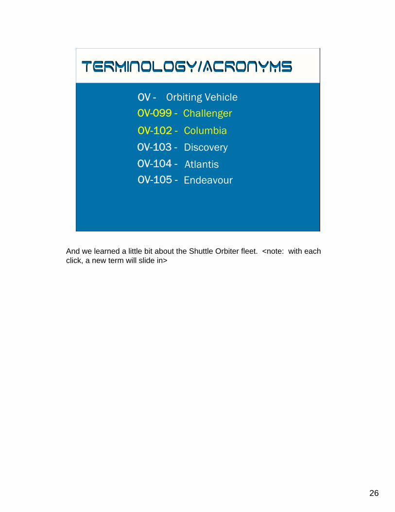
Terminology/Acronyms
Orbiting Vehicle
Challenger
Columbia
Discovery
AtlantisEndeavour
OV -OV-099 -
OV-102 -
OV-103 -
OV-104 -
OV-105 -
And we learned a little bit about the Shuttle Orbiter fleet. <note: with each click, a new term will slide in>
27
Your Mission
Now that you’ve learned everything you can about the Space Shuttle, complete these fun activities per your teacher’s directions.
• Scavenger Hunt• Word Search• Crossword• Orbiter Labeling
This slide will need to be updated from time to time. To get the latest orbiter statistics, visit:http://www.nasa.gov/centers/kennedy/news/facts/shuttlefacts-toc.html