Embed Size (px)
Citation preview


1
This Owner Handbook describes all Fiat SEDICI versions. As a consequence, you should consider only the information which is related to the engine and bodywork version of the vehicle you purchased.
Dear Customer,
Thank you for selecting Fiat and congratulations on your choice of a Fiat SEDICI.
We have written this handbook to help you get to know all your new vehicle features and use it in the best possible way.
You should read it right through before taking the road for the first time.
You will find information, tips and important warnings regarding the driving of your vehicle to help you derive the maximum fromyour Fiat SEDICI technological features.
What’s more every single component of the Fiat SEDICI is fully recyclable. At the end of your vehicle’s useful lifespan any FiatDealership will be pleased to make arrangements for your vehicle to be recycled and nature benefits in two ways: there’s no pol-lution from waste disposal and the demand for raw materials is reduced.
The enclosed Warranty Booklet lists the services that Fiat offers to its Customers:
� the Warranty Certificate with terms and conditions for maintaining its validity
� the range of additional services available to Fiat Customers.
Best regards and good motoring!
001-008 SEDICI LUM FL GB 1E 19-06-2009 13:27 Pagina 1

2
By choosing Fiat original spare parts (re-conditioned and non re-conditioned) youcan rely on a rapid and efficient serviceprovided by skilled operators, on goodequipment and a wide range of parts.
The Fiat Dealership uses Fiat original spareparts and re-conditioned spare parts.
FIAT RE-CONDITIONED SPARE PARTS
They are Fiat original spare parts/me-chanical assemblies, already used but giv-en back to Fiat, which renews them com-pletely to meet the same qualitative andreliability requirements of the newly orig-inal spare parts.
Fiat re-conditioned spare parts:
� give the Customers the opportunity tobuy spare mechanical assemblies (en-gines, transmissions, etc.) at particular-ly favourable prices;
� contribute to safeguard the environ-ment by reducing scrapping operationsand the disposal of removed materials.
FIAT ORIGINAL SPARE PARTS
These spare parts ensure the reliabilityand technological quality needed to trav-el safely. Designed on the basis of the sameproject of the components fitted on thevehicle, the original spare parts undergovery harsh tests before being produced orre-conditioned, with the aim of being usedto keep the vehicle performance un-changed in time.
Therefore, for an accurate and carefulmaintenance, choose Fiat original spareparts (re-conditioned and non re-condi-tioned), which can be identified by the fea-tures of their package and which are avail-able only at the Fiat Dealership.
FIAT ORIGINAL SPARE PARTS AND FIAT RE-CONDITIONED SPARE PARTS
001-008 SEDICI LUM FL GB 1E 19-06-2009 13:27 Pagina 2

3
SERVICE STATION GUIDE
1. Fuel (see section 1)
2. Engine hood (see section 4)
3. Tire changing tools (see section 4)
4. Engine oil dipstick (Yellow)(see section 8)
5. Automatic transaxle fluid dipstick(Red or Orange) (see section 8)
6. Engine coolant (see section 8)
7. Windshield washer fluid(see section 8)
8. Battery (see section 8)
9. Tire pressure (see Tire InformationLabel on driver’s door lock pillar)
10. Spare tire (see section 8)
LHD: Left Hand Drive
RHD: Right Hand Drive
(RHD)
2
2
(LHD)2
4
7
6
(LHD) 19
(RHD)9
3
10
8
5
6
79JF017
(Diesel Engine Model)
001-008 SEDICI LUM FL GB 1E 19-06-2009 13:27 Pagina 3
4
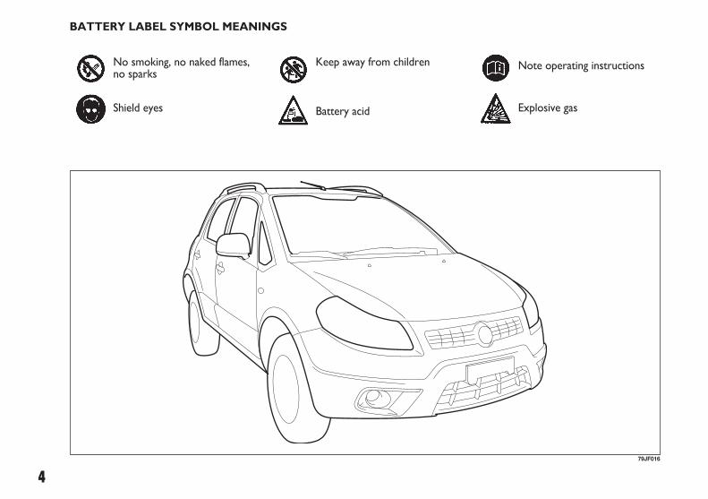
BATTERY LABEL SYMBOL MEANINGS
79JF016
No smoking, no naked flames,no sparks
Shield eyes
Keep away from children
Battery acid
Note operating instructions
Explosive gas
001-008 SEDICI LUM FL GB 1E 19-06-2009 13:27 Pagina 4

5
All information in this manual is based onthe latest product information available atthe time of publication. Due to improve-ments or other changes, there may be dis-crepancies between information in thismanual and your vehicle. Fiat reserves theright to make production changes at anytime, without notice and without incurringany obligation to make the same or simi-lar changes to vehicles previously built orsold.
This vehicle may not comply with stan-dards or regulations of other countries.Before attempting to register this vehiclein any other country, check all applicableregulations and make any necessary mod-ifications.
IMPORTANT
Please read this manual and follow its in-structions carefully. To emphasize specialinformation, the symbol " and the wordsWARNING, IMPORTANT and NOTEhave special meanings. These specialmeanings apply except when laws or reg-ulations require that the signal words beused with a different meaning.
Pay special attention to the messages high-lighted by these signal words:
FOREWORD
This manual should be considered a per-manent part of the vehicle and should re-main with the vehicle when resold or oth-erwise transferred to a new owner or op-erator. Please read this manual carefullybefore operating your new Fiat and reviewthe manual from time to time. It containsimportant information on safety, opera-tion and maintenance.
Indicates a potential hazardthat could result in death or
injury.
WARNING
IMPORTANT Indicates a potential hazardthat could result in vehicle damage.
NOTE Indicates special information tomake maintenance easier or instructionsclearer.
001-008 SEDICI LUM FL GB 1E 19-06-2009 13:27 Pagina 5
6
IMPORTANT Improper installation ofmobile communication equipment such ascellular telephones or CB (Citizen’s Band)radios may cause electronic interferencewith your vehicle’s ignition system, re-sulting in vehicle performance problems.Consult your Fiat Dealership or qualifiedservice technician for advice on installingsuch mobile communication equipment.
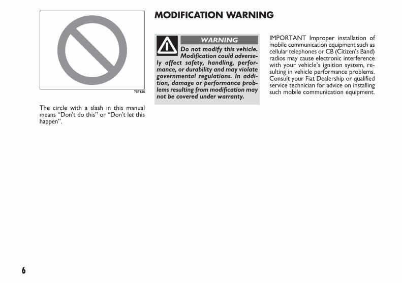
The circle with a slash in this manualmeans “Don’t do this” or “Don’t let thishappen”.
MODIFICATION WARNING
Do not modify this vehicle.Modification could adverse-
ly affect safety, handling, perfor-mance, or durability and may violategovernmental regulations. In addi-tion, damage or performance prob-lems resulting from modification maynot be covered under warranty.
WARNING
75F135
001-008 SEDICI LUM FL GB 1E 19-06-2009 13:27 Pagina 6

BEFORE DRIVING
STEERING COLUMN CONTROLS
INSTRUMENT PANEL
OTHER CONTROLS AND EQUIPMENT
OPERATING YOUR VEHICLE
DRIVING TIPS
VEHICLE LOADING AND TOWING
INSPECTION AND MAINTENANCE
EMERGENCY SERVICE
BODY WORK CARE
GENERAL INFORMATION
TECHNICAL SPECIFICATIONS
SUPPLEMENT
INDEX
TTAABBLLEE OOFF CCOONNTTEENNTTSS 1
2
3
4
5
6
7
8
9
10
11
12
13
14
001-008 SEDICI LUM FL GB 1E 19-06-2009 13:27 Pagina 7

Page left blank voluntarily.
001-008 SEDICI LUM FL GB 1E 19-06-2009 13:27 Pagina 8

9
BBEEFFOORREE DDRRIIVVIINNGG
60G404
FUEL RECOMMENDATION.............................................. 10
KEYS......................................................................................... 11
DOOR LOCKS...................................................................... 12
WINDOWS............................................................................ 24
MIRRORS ................................................................................ 27
SEAT ADJUSTMENT............................................................ 28
ADJUSTABLE HEAD RESTRAINTS (for versions/markets, where provided)........................... 30
SEAT BELTS AND CHILD RESTRAINT SYSTEMS ....... 31
CHILD RESTRAINT SYSTEM FOR EU COUNTRIES .. 40
SUPPLEMENTAL RESTRAINT SYSTEM (AIR BAGS) (for versions/markets, where provided)........................... 47
1
009-056 SEDICI LUM FL GB 1E 19-06-2009 14:11 Pagina 9
10
Gasoline/Ethanol blends
Blends of unleaded gasoline and ethanol(grain alcohol), also known as gasohol, arecommercially available in some areas.Blends of this type may be used in your ve-hicle if they are no more than 10%ethanol. Make sure this gasoline- ethanolblend has octane ratings no lower thanthose recommended for gasoline.
Gasoline/Methanol blends
Blends of unleaded gasoline and methanol(wood alcohol) are also commercially avail-able in some areas. DO NOT USE fuelscontaining more than 5% methanol underany circumstances. Fuel system damage orvehicle performance problems resultingfrom the use of such fuels are not the re-sponsibility of Fiat and may not be coveredunder the New Vehicle Warranty.
Fuels containing 5% or less methanol maybe suitable for use in your vehicle if theycontain cosolvents and corrosion in-hibitors.
NOTE If you are not satisfied with the dri-veability or fuel economy of your vehiclewhen you are using a gasoline/ alcoholblend, you should switch back to unlead-ed gasoline containing no alcohol.
IMPORTANT Be careful not to spill fuelcontaining alcohol while refueling. If fuel isspilled on the vehicle body, wipe it up im-mediately. Fuels containing alcohol cancause paint damage, which is not coveredunder the New Vehicle Limited Warran-ty.
DIESEL ENGINE
The diesel fuel should be with Cetane In-dex higher than 50 and sulfur content lessthan 50 ppm (parts per million). Youshould use the diesel fuel conformable toEN590 that corresponded to Euro V emis-sion control. Do not use marine diesel fu-el, heating oils and so forth. If you use im-proper diesel fuel, it may cause serious en-gine damage.
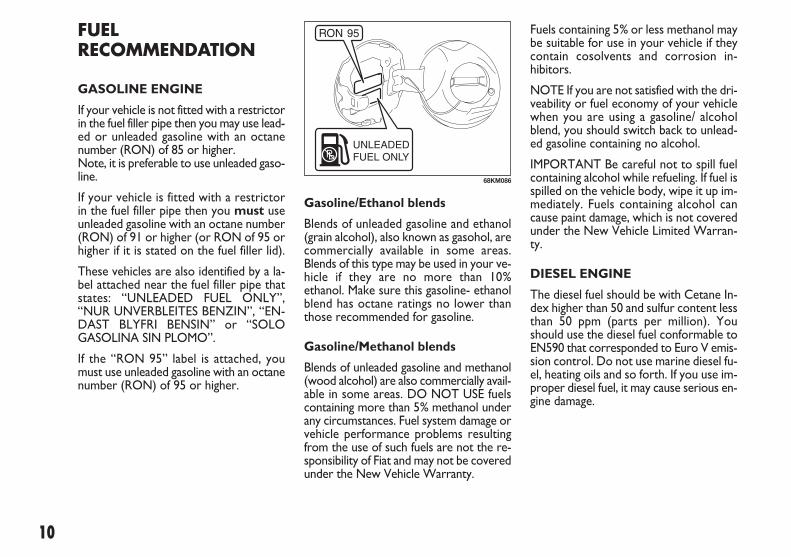
FUELRECOMMENDATION
GASOLINE ENGINE
If your vehicle is not fitted with a restrictorin the fuel filler pipe then you may use lead-ed or unleaded gasoline with an octanenumber (RON) of 85 or higher. Note, it is preferable to use unleaded gaso-line.
If your vehicle is fitted with a restrictorin the fuel filler pipe then you must useunleaded gasoline with an octane number(RON) of 91 or higher (or RON of 95 orhigher if it is stated on the fuel filler lid).
These vehicles are also identified by a la-bel attached near the fuel filler pipe thatstates: “UNLEADED FUEL ONLY”,“NUR UNVERBLEITES BENZIN”, “EN-DAST BLYFRI BENSIN” or “SOLOGASOLINA SIN PLOMO”.
If the “RON 95” label is attached, youmust use unleaded gasoline with an octanenumber (RON) of 95 or higher.
68KM086
009-056 SEDICI LUM FL GB 1E 19-06-2009 14:11 Pagina 10

11
IMPORTANT The vehicle must only befilled with diesel fuel for motor vehicles,in compliance with European StandardEN590. The use of other products or mix-tures may irreparably damage the enginewith invalidation of the warranty due tothe damage caused. In the event of acci-dentally filling with another type of fuel, donot start the engine and empty the tank.If the engine has been run even for only avery short time, in addition to the tank,it is also necessary to drain out the wholefuel circuit.
IMPORTANT The fuel tank has an airspace to allow for fuel expansion in hotweather. If you continue to add fuel afterthe filler nozzle has automatically shut offor an initial blowback occurs, the airchamber will become full. Exposure toheat when fully fuelled in this manner willresult in leakage due to fuel expansion. Toprevent such fuel leakage, stop filling af-ter the filler nozzle has automatically shutoff, or when using an alternative non au-tomatic system, initial vent blowback oc-curs.
Do not put naked flames orlighted cigarettes near the
fuel filler hole as there is a danger offire. Do not bend too close to the holeeither so as not to breathe in harmfulvapours.
WARNING
Fiat CODE - Immobilizer System (for versions/markets, where provided)
This system is designed to help preventvehicle theft by electronically disabling theengine starting system.
The engine can be started only with yourvehicle’s original immobilizer ignition keywhich has an electronic identification codeprogrammed into it. The key communi-cates the identification code to the vehi-cle when the key is turned to the “ON”position. If you need to make spare keys,see your Fiat Dealership. The vehicle mustbe programmed with the correct identi-fication code for the spare keys. A keymade by an ordinary locksmith will notwork.
KEYS
Your vehicle comes with a pair of identi-cal keys. Keep the spare key in a safe place.One key can open all of the locks on thevehicle.
The key identification number is stampedon a metal tag provided with the keys oron the keys. Keep the tag (for versions/markets, where provided) in a safe place.If you lose your keys, you will need thisnumber to have new keys made.
IMPORTANT All the keys and the metaltag must be handed over to the new own-er when selling the vehicle.
79J020
009-056 SEDICI LUM FL GB 1E 19-06-2009 14:11 Pagina 11

12
DOOR LOCKS
SIDE DOOR LOCKS
To lock a front door from outside the ve-hicle:
❒ Insert the key and turn the top of thekey toward the rear of the vehicle, or
❒ Turn the lock knob forward, then pulland hold the door handle as you closethe door.
To unlock a front door from outside thevehicle, insert the key and turn the top ofthe key toward the front of the vehicle.
To lock a door from inside the vehicle,turn the lock knob forward. Turn the lockknob rearward to unlock the door.
To lock a rear door from outside the ve-hicle, turn the lock knob forward andclose the door. You do not need to pulland hold the door handle as you close thedoor.
NOTE Be sure to hold the door handlewhen you close a locked front door, orthe door will not remain locked.
❒ In case of attaching any metal objectsto the immobilizer key, it may not startthe engine.
IMPORTANT The immobilizer key is asensitive electronic instrument. To avoiddamaging the immobilizer key:
❒ Do not expose it to impacts, moistureor high temperature such as on thedashboard under direct sunlight.
❒ Keep the immobilizer key away frommagnetic objects.
IMPORTANT The electronic componentsinside the key may be damaged if the keyis submitted to sharp knocks.
This immobilizer system, model 5WK49181and 5WK49182 for gasoline engine ormodel 5WK49183 and 5WK49184 fordiesel engine are in compliance with theessential requirements and other provi-sions of the Directive 1999/5/EC.
Ignition Key Reminder (for versions/markets, where provided)
A buzzer sounds intermittently to remindyou to remove the ignition key if it is inthe ignition switch when the driver’s dooris opened.
If the immobilizer system light (1) for gaso-line engine or service vehicle soon (SVS)light (2) for diesel engine blinks when theignition switch is in the “ON” position, theengine will not start.
NOTE If this light blinks, turn the ignitionswitch to the “LOCK” position, then turnit back to the “ON” position. If the lightstill blinks with the ignition switch turnedto the “ON” position, there may be some-thing wrong with your key or with the im-mobilizer system. Ask your Fiat dealer toinspect the system.
NOTE
❒ If you lose your Immobilizer ignitionkey, see your Fiat Dealership as soonas possible to have the lost one deac-tivated, then have the new key made bythem.
❒ If you own other vehicles with immo-bilizer keys, keep those keys away fromthe ignition switch when using your Fiat, or the engine may not be startedbecause they may interfere with yourFiat’s immobilizer system.
(1) (2)
62J127
009-056 SEDICI LUM FL GB 1E 19-06-2009 14:11 Pagina 12

13
60B008
UNLOCK
LOCKRear
Front
79J021
UNLOCKLOCK
You can also lock or unlock all doors bydepressing the front or rear of the switch,respectively.
NOTE
❒ If your vehicle is equipped with the key-less entry system, you can also lock orunlock all doors by operating the trans-mitter. Refer to “Keyless Entry System”in this section.
❒ If your vehicle is equipped with the key-less start system, you can also lock orunlock all doors by pushing the requestswitch on the door handle. Refer to“Keyless Start System” in this section.
CENTRAL DOOR LOCKINGSYSTEM (for versions/markets, where provided)
You can lock and unlock all doors (in-cluding the rear door) simultaneously byusing the key in the driver’s door lock.
To lock all doors simultaneously, insertthe key in the driver’s door lock and turnthe top of the key toward the rear of thevehicle once.
To unlock all doors simultaneously, insertthe key in the driver’s door lock and turnthe top of the key toward the front of thevehicle twice.
To unlock the driver’s door only, insertthe key in that door lock and turn the topof the key toward the front of the vehi-cle once.
54G294
UNLOCK LOCKRear
Front
80JM009
009-056 SEDICI LUM FL GB 1E 19-06-2009 14:11 Pagina 13

14
To activate this system:
Insert the key in the driver’s door lock andturn the top of the key toward the rear ofthe vehicle twice within 3 seconds.
You can not use the lock knobs to unlockthe side doors when this system is acti-vated.
NOTE
❒ The dead lock system will not operateif one or more door(s) is(are) notclosed and latched completely. Makesure all doors are completely closedand latched when activating the deadlock system.
❒ The dead lock system is released au-tomatically allowing all the side doorsto be unlocked when the ignition switchis turned to the “ON” position.
Do not activate the deadlock system if there are oc-
cupants in the vehicle. They will belocked in the vehicle and cannot un-lock the doors from inside.
WARNING
83E107
Rear
2 times
Front
DEAD LOCK SYSTEM (for versions/markets, where provided)
This system is designed to help preventtamper-unlocking of the door locks.
You can activate this system by turning thekey in the driver’s door lock.
NOTE
❒ If your vehicle is equipped with the key-less entry system, you can activate thedead lock system by operating thetransmitter. Refer to “Keyless EntrySystem” in this section.
❒ If your vehicle is equipped with the key-less start system, you can activate thedead lock system by pushing the re-quest switch on the door handle. Referto “Keyless Start System” in this sec-tion.
009-056 SEDICI LUM FL GB 1E 19-06-2009 14:11 Pagina 14
15
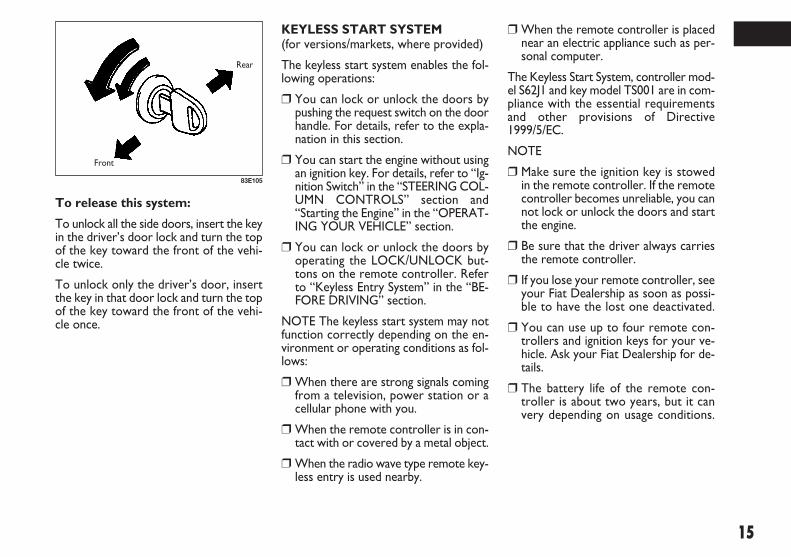
To release this system:
To unlock all the side doors, insert the keyin the driver’s door lock and turn the topof the key toward the front of the vehi-cle twice.
To unlock only the driver’s door, insertthe key in that door lock and turn the topof the key toward the front of the vehi-cle once.
83E105
Rear
Front
❒ When the remote controller is placednear an electric appliance such as per-sonal computer.
The Keyless Start System, controller mod-el S62J1 and key model TS001 are in com-pliance with the essential requirementsand other provisions of Directive1999/5/EC.
NOTE
❒ Make sure the ignition key is stowedin the remote controller. If the remotecontroller becomes unreliable, you cannot lock or unlock the doors and startthe engine.
❒ Be sure that the driver always carriesthe remote controller.
❒ If you lose your remote controller, seeyour Fiat Dealership as soon as possi-ble to have the lost one deactivated.
❒ You can use up to four remote con-trollers and ignition keys for your ve-hicle. Ask your Fiat Dealership for de-tails.
❒ The battery life of the remote con-troller is about two years, but it canvery depending on usage conditions.
KEYLESS START SYSTEM (for versions/markets, where provided)
The keyless start system enables the fol-lowing operations:
❒ You can lock or unlock the doors bypushing the request switch on the doorhandle. For details, refer to the expla-nation in this section.
❒ You can start the engine without usingan ignition key. For details, refer to “Ig-nition Switch” in the “STEERING COL-UMN CONTROLS” section and“Starting the Engine” in the “OPERAT-ING YOUR VEHICLE” section.
❒ You can lock or unlock the doors byoperating the LOCK/UNLOCK but-tons on the remote controller. Referto “Keyless Entry System” in the “BE-FORE DRIVING” section.
NOTE The keyless start system may notfunction correctly depending on the en-vironment or operating conditions as fol-lows:
❒ When there are strong signals comingfrom a television, power station or acellular phone with you.
❒ When the remote controller is in con-tact with or covered by a metal object.
❒ When the radio wave type remote key-less entry is used nearby.
009-056 SEDICI LUM FL GB 1E 19-06-2009 14:11 Pagina 15

16
The turn signal lights will flash once whenthe doors are locked and then the turnsignal lights will flash once again when thedoors are locked with the dead lock sys-tem.
Keyless unlocking/lockingoperation
When the remote controller is within theaccess range, you can lock or unlock thedoors by pushing the request switch (1)on the door handle of the driver’s door,front passenger’s door or rear door. If youwant to prevent tamper- unlocking of thedoor locks, you can activate the dead locksystem.
To lock or dead lock all doors when alldoors are unlocked:
❒ To lock all doors, push the requestswitch on one of the door handlesonce.
❒ To lock all doors with the dead locksystem, push the request switch on oneof the door handles twice within about3 seconds.
(1)
79J023
Do not activate the deadlock system if there are oc-
cupants in the vehicle. They will belocked in the vehicle and cannot un-lock the doors from inside.
WARNING
To unlock a door or all doors:
❒ To unlock the door only, push the re-quest switch on the door handle once.
❒ To unlock other doors, push the re-quest switch on the door handle onceagain.
To stow the ignition key in the remotecontroller, push the key in the remotecontroller until the click is heard.
62J004
(A)
62J005
To remove the key from the remote con-troller, push the button (A) in the direc-tion of the arrow and pull the key outfrom the remote controller.
009-056 SEDICI LUM FL GB 1E 19-06-2009 14:11 Pagina 16
17
When the door(s) is(are) unlocked:
❒ the turn signal lights will flash twice, and
❒ the interior light will turn on for about15 seconds and then fade out with theinterior light switch in the middle po-sition. If you push the ignition switchduring that time, the light will start tofade out immediately.
Be sure the doors are locked after you op-erate the request switch to lock.
NOTE
❒ The door locks can not be operated bythe request switch under the follow-ing conditions:
– if any door is open or incompletelyclosed;
– if the ignition switch is in a positionother than LOCK;
– if the ignition key is inserted in the ig-nition switch.
❒ If no doors are opened within about 30seconds after unlocking by pushing therequest switch, the doors will be lockedautomatically again.
❒ If a spare remote controller is in the ve-hicle, the request switches may not op-erate normally.
❒ The remote controller will only oper-ate a request switch if it is within theswitch’s operating range. For example,if the remote controller is within theoperating range of the driver’s door re-quest switch, the driver’s door switchcan be operated but the front passen-ger’s door switch or rear door switchcan not be operated.
IMPORTANT The remote controller isa sensitive electronic instrument. To avoiddamaging the remote controller:
❒ Do not expose it to impacts, moistureor high temperature such as on thedashboard under direct sunlight.
❒ Keep the remote controller away frommagnetic objects such as a television.
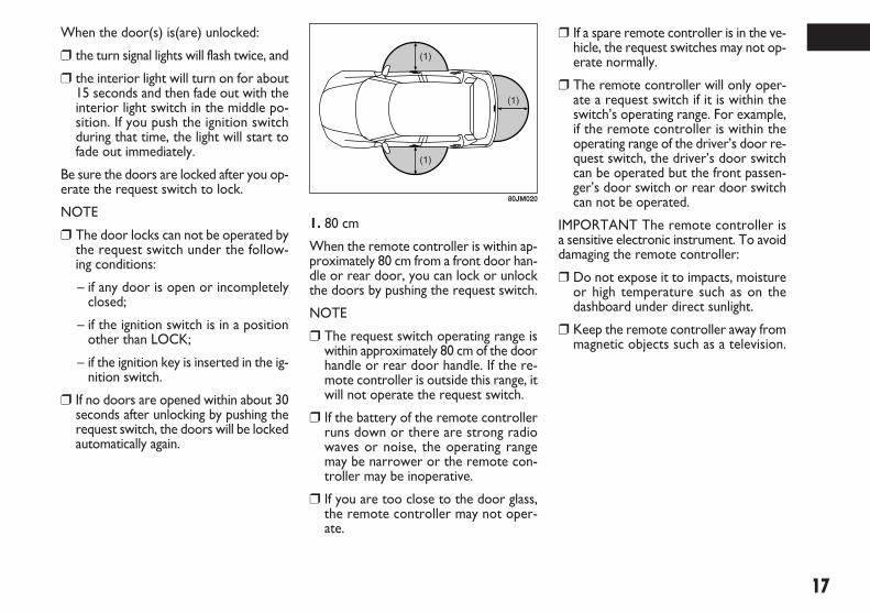
1. 80 cm
When the remote controller is within ap-proximately 80 cm from a front door han-dle or rear door, you can lock or unlockthe doors by pushing the request switch.
NOTE
❒ The request switch operating range iswithin approximately 80 cm of the doorhandle or rear door handle. If the re-mote controller is outside this range, itwill not operate the request switch.
❒ If the battery of the remote controllerruns down or there are strong radiowaves or noise, the operating rangemay be narrower or the remote con-troller may be inoperative.
❒ If you are too close to the door glass,the remote controller may not oper-ate.
(1)
(1)
(1)
80JM020
009-056 SEDICI LUM FL GB 1E 19-06-2009 14:11 Pagina 17

18
KEYLESS ENTRY SYSTEM(for versions/markets, where provided)
(1) “LOCK” button
(2) “UNLOCK” button
There are two ways to lock or unlock alldoors simultaneously by operating thetransmitter/remote controller near thevehicle.
If the remote controller is left in the ve-hicle and you lock the door in the follow-ing manner, the driver’s door or the frontpassenger’s door will be automatically un-locked.
❒ You open the driver’s door and lockthe door by turning the lock knob for-ward or pushing the power door lock-ing switch, the driver’s door will be au-tomatically unlocked.
❒ You open the door (s) except the dri-ver’s door and lock the front passen-ger’s door by turning the lock knob for-ward or pushing the power door lock-ing switch, the front passenger’s doorwill be automatically unlocked.
NOTE
❒ The reminder will not operate whenthe remote controller is on the instru-ment panel, in the glove box, in thedoor pocket, in the sun visor or on thefloor etc.
❒ Be sure that the driver always carriesthe remote controller.
❒ Do not leave the remote controller inthe vehicle when departing from the ve-hicle.
(1)
(2)
81A184
Type 1
Reminder function
If the remote controller is not in the vehi-cle under the following condition, a buzzersounds intermittently for about 2 secondsand the keyless start system indicator lighton the instrument cluster blinks in red:
❒ When the vehicle speed is over 10 km/h.
❒ When the door (s) has (have) openedand later all doors are closed with theignition switch in a position other thanLOCK.
The red indicator light will turn off withinseveral seconds after the remote controlleris returned in the vehicle except in the rearluggage area.
79JF001
009-056 SEDICI LUM FL GB 1E 19-06-2009 14:11 Pagina 18

19
Central door locking system
❒ To lock all doors, push the “LOCK”button (1) once.
❒ To unlock only the driver’s door, pushthe “UNLOCK” button (2) once.
❒ To unlock other doors, push the “UN-LOCK” button (2) once again.
189001
Type 2
The turn signal lights will flash once whenthe doors are locked and then the turnsignal lights will flash once again when thedoors are locked with the dead lock sys-tem.
When the door (s) is (are) unlocked:
❒ The turn signal lights will flash twice,and
❒ the interior light will turn on for about15 seconds and then fade out with theinterior light switch in the middle po-sition. If you insert the key into the ig-nition switch during that time, the lightwill start to fade out immediately.
Be sure the doors are locked after you op-erate the “LOCK” button (1).
If no door is opened within about 30 sec-onds after the “UNLOCK” button (2) isoperated, the doors will automatically lockagain.
Central door locking system withthe dead lock system (for versions/markets, where provided)
If you want to prevent tamper- unlockingof the door locks, use this method. Whenthe dead lock system is activated, oper-ating the lock knobs will not unlock theside doors.
To activate this system:
To lock all doors, push the “LOCK” but-ton (1) twice within 3 seconds.
To release this system:
❒ To unlock only the driver’s door, pushthe “UNLOCK” button (2) once.
❒ To unlock other doors, push the “UN-LOCK” button (2) once again.
Do not activate the deadlock system if there are oc-
cupants in the vehicle. They will belocked in the vehicle and cannot un-lock the doors from inside.
WARNING
009-056 SEDICI LUM FL GB 1E 19-06-2009 14:11 Pagina 19

20
Replacement of the battery
If the transmitter/ remote controller be-comes unreliable, replace the battery.
To replace the battery for thetransmitter of the keyless entry
❒ Remove the screw (1), and open thetransmitter cover.
❒ Remove the transmitter (2).
Type 1
The Keyless Entry System, Transmittermodel TS002 and Receiver model R51K0are in compliance with the essential re-quirements and other provisions of Di-rective 1999/5/EC.
Type 2
The Keyless Start System, controller mod-el S62J1 and key model TS001 are in com-pliance with the essential requirementsand other provisions of Directive1999/5/EC.
IMPORTANT The transmitter/remotecontroller is a sensitive electronic instru-ment. To avoid damaging the transmit-ter/remote controller:
❒ Do not expose it to impacts, moistureor high temperature such as on thedashboard under direct sunlight.
❒ Keep the transmitter/remote con-troller away from magnetic objectssuch as a television.
(1)
(2)
81A185
NOTE
❒ The maximum operating distance isabout 5 meter (16 ft.), but this can varydepending on the surroundings, espe-cially near other transmitting devicessuch as radio towers or CB (Citizen’sBand) radios.
❒ The door locks can not be operatedwith the transmitter/remote controller:
– if the ignition switch is in a positionother than “LOCK” or the ignitionkey is inserted in the ignition switch,or
– if any door is open or incompletelyclosed.
❒ If you lose your transmitter/remotecontroller, ask your Fiat Dealership assoon as possible for a replacement andto have the lost one deactivated.
009-056 SEDICI LUM FL GB 1E 19-06-2009 14:11 Pagina 20

21
❒ Put the edge of a coin or a flat bladescrew driver in the slot of the trans-mitter (2) and pry it open.
❒ Replace the battery (3) (Lithium disc-type CR1620 or equivalent) so its +terminal faces the “+” mark of thetransmitter.
❒ Close the transmitter and install it in-to the transmitter holder.
❒ Close the transmitter cover, install andtighten the screw (1).
❒ Make sure the door locks can be op-erated with the transmitter.
❒ Dispose of the used battery properlyaccording to applicable rules or regula-tions. Do not dispose of lithium bat-teries with ordinary household trash.
(2)
(3)
80JM135
To replace the battery for theremote controller of the keylessstart system
❒ Insert a flat blade screw driver coveredwith a soft cloth in the slit of the re-mote controller and pry it open.
❒ Replace the battery (1) (Lithium disctype CR2032 or equivalent) so its +terminal faces the bottom of the caseas shown in the illustration.
❒ Close the remote controller firmly.
❒ Make sure the door locks can be op-erated with the remote controller.
189002 189003
Swallowing a lithium batterymay cause serious internal
injury. Do not allow anyone to swal-low a lithium battery. Keep lithiumbatteries away from children andpets. If swallowed, contact physicianimmediately.
WARNING
IMPORTANT The transmitter/remotecontroller is a sensitive electronic instru-ment. To avoid damaging it, do not exposeit to dust or moisture or tamper with in-ternal parts.
NOTE Used batteries must be disposedproperly according to applicable rules orregulations and must not be disposed withordinary household trash.
009-056 SEDICI LUM FL GB 1E 19-06-2009 14:11 Pagina 21

22
Child-Proof Locks (rear side door)
1. LOCK2. UNLOCK
As illustrated, a child-proof lock is pro-vided for both rear doors. When the locklever is in position (1), the child-proof lockis locked, and when in position (2), thechildproof lock is unlocked. When thechildproof lock is in the locked position,the rear door cannot be opened from theinside even if the inside door lock is un-locked but can be opened from the out-side.
(1)
(2)
79J025
Be sure to place the child-proof lock in the locked po-
sition whenever children are seated inthe rear.
WARNING
1. Crossed-out wheeled bin symbol
The crossed-out wheeled bin symbol (1)indicates that used battery should be col-lected separately from ordinary householdtrash.
By ensuring the used battery is disposedor recycled correctly, you will help pre-vent potential negative consequences forthe environment and human health, whichcould otherwise be caused by inappropri-ate trash handling of the battery. The re-cycling of materials will help to conservenatural resources. For more detailed in-formation about disposing or recycling ofthe used battery, consult your FIAT Deal-ership.
After engaging the child lockon both rear doors, check for
proper engagement by trying to opena rear door with the internal handle.
WARNING
(1)
80JM133
009-056 SEDICI LUM FL GB 1E 19-06-2009 14:11 Pagina 22
23
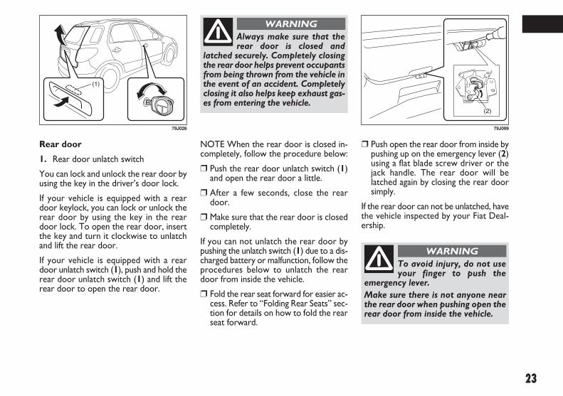
Rear door
1. Rear door unlatch switch
You can lock and unlock the rear door byusing the key in the driver’s door lock.
If your vehicle is equipped with a reardoor keylock, you can lock or unlock therear door by using the key in the reardoor lock. To open the rear door, insertthe key and turn it clockwise to unlatchand lift the rear door.
If your vehicle is equipped with a reardoor unlatch switch (1), push and hold therear door unlatch switch (1) and lift therear door to open the rear door.
NOTE When the rear door is closed in-completely, follow the procedure below:
❒ Push the rear door unlatch switch (1)and open the rear door a little.
❒ After a few seconds, close the reardoor.
❒ Make sure that the rear door is closedcompletely.
If you can not unlatch the rear door bypushing the unlatch switch (1) due to a dis-charged battery or malfunction, follow theprocedures below to unlatch the reardoor from inside the vehicle.
❒ Fold the rear seat forward for easier ac-cess. Refer to “Folding Rear Seats” sec-tion for details on how to fold the rearseat forward.
(1)
79J026
Always make sure that therear door is closed and
latched securely. Completely closingthe rear door helps prevent occupantsfrom being thrown from the vehicle inthe event of an accident. Completelyclosing it also helps keep exhaust gas-es from entering the vehicle.
WARNING
❒ Push open the rear door from inside bypushing up on the emergency lever (2)using a flat blade screw driver or thejack handle. The rear door will belatched again by closing the rear doorsimply.
If the rear door can not be unlatched, havethe vehicle inspected by your Fiat Deal-ership.
(2)
79J099
To avoid injury, do not useyour finger to push the
emergency lever.Make sure there is not anyone nearthe rear door when pushing open therear door from inside the vehicle.
WARNING
009-056 SEDICI LUM FL GB 1E 19-06-2009 14:11 Pagina 23

24
(1)
(2)
80JM010
ELECTRIC WINDOWCONTROLS (for versions/markets, where provided)
The electric windows can only be oper-ated when the ignition switch is in the“ON” position.
Driver’s side (type A)
WINDOWS
MANUAL WINDOW CONTROL(for versions/markets, where provided)
Raise or lower the door windows by turn-ing the handle located on the door panel.
60G010
009-056 SEDICI LUM FL GB 1E 19-06-2009 14:11 Pagina 24

25
Passenger’s door
The passenger’s door has a switch (3) tooperate the passenger’s window.
Driver’s side
The driver’s door has a switch (1) to op-erate the driver’s window, and a switch(2) to operate the front passenger’s win-dow or there are switches (4), (5), to op-erate the rear left and right passenger win-dows, respectively.
(1)
(2)
(4)
(5)
80JC095
(3)
79J029
Driver’s side (type B) Passenger’s door
To open a window, push the top part ofthe switch and to close the window lift upthe top part of the switch.
The driver’s window has an “auto-down”feature for added convenience (at tollbooths or drive-through restaurants, forexample). This means you can open thewindow without holding the windowswitch in the “Down” position. Press thedriver’s window switch completely downand release it. To stop the window beforeit reaches the bottom, pull the switch upbriefly.
81A009
CLOSE
OPEN
009-056 SEDICI LUM FL GB 1E 19-06-2009 14:11 Pagina 25

26
NOTE The rear side door windows arenot designed to open fully. They can beopened about 2/3 of the way down.
NOTE If you drive with one of the rearwindows open, you may hear a loud soundcaused by air vibration. To reduce thesound, open the driver’s or front passen-ger’s window, or narrow the rear windowopening.
79J207
The driver’s door also has a lock switchfor the passenger’s window (s). When youpush in the lock switch, the passenger’swindow (s) can not be raised or loweredby operating any of the switches (2), (3),(4) or (5). To restore normal operation,release the lock switch by pushing again.
80JM011 80JC097
Lock switch (type A) Lock switch (type B)
You should always lock thepassenger’s window opera-
tion when there are children in the ve-hicle. Children can be seriously in-jured if they get part of their bodycaught by the window during opera-tion.To avoid injuring an occupant by win-dow entrapment, be sure no part ofthe occupant’s body such as hands orhead is in the path of the electric win-dows when closing them.Always remove the ignition key whenleaving the vehicle even if a shorttime. Also do not leave children alonein a parked vehicle. Unattended chil-dren could use the electric windowswitches and get trapped by the win-dow.
WARNING
009-056 SEDICI LUM FL GB 1E 19-06-2009 14:11 Pagina 26

27
MIRRORS
INSIDE REARVIEW MIRROR
You can adjust the inside rearview mirrorby hand so as to see the rear of your ve-hicle in the mirror. To adjust the mirror,set the selector tab (1) to the day posi-tion, then move the mirror up, down orsideways by hand to obtain the best view.
When driving at night, you can move theselector tab to the night position to re-duce glare from the headlights of vehiclesbehind you.
79J032
(1)
65D409
Day drivingNight driving
Always adjust the mirrorwith the selector set to the
day position.
WARNING Only use the night positionif it is necessary to reduce
glare from the headlights of vehiclesbehind you. Be aware that in this po-sition you may not be able to seesome objects that could be seen in theday position.
WARNING
OUTSIDE REARVIEW MIRRORS
Adjust the outside rearview mirrors soyou can just see the side of your vehicle inthe mirrors.
79J033
Be careful when judging thesize or distance of a vehicle
or other object seen in the side con-vex mirror. Be aware that objectslook smaller and appear farther awaythan when seen in a flat mirror.
WARNING
009-056 SEDICI LUM FL GB 1E 19-06-2009 14:11 Pagina 27

28
ELECTRIC MIRRORS (for versions/markets, where provided)
The switch to control the electric mirrorsis located on the driver’s door panel. Youcan adjust the mirrors when the ignitionswitch is in the “ACC” or “ON” position.
To adjust the mirrors:
❒ Move the selector switch to the left orright to select the mirror you wish toadjust.
❒ Press the outer part of the switch thatcorresponds to the direction in whichyou wish to move the mirror.
❒ Return the selector switch to the cen-ter position to help prevent unintend-ed adjustment.
SEAT ADJUSTMENT
(2)
(4)
(3)
(1) (1)
(3)(2)
(4)
79J034
Only make adjustments whenthe vehicle is stationary.
WARNING
To avoid excessive seat beltslack, which reduces the ef-
fectiveness of the seat belts as a safe-ty device, make sure that the seatsare adjusted before the seat belts arefastened.
WARNING
Check that the seat is firmlylocked in the runners by try-
ing to move it back and forth. Failureto lock the seat in place could resultin the seat moving suddenly and thedriver losing control of the vehicle.
WARNING
NOTE If your vehicle is equipped with theheated outside rearview mirrors, refer to“Heated Rear Window and Heated Out-side Rearview Mirrors (for versions/markets, where provided) Switch” in the“INSTRUMENT PANEL” section.
009-056 SEDICI LUM FL GB 1E 19-06-2009 14:11 Pagina 28

29
If the driver’s seat is equipped with a seatheight adjuster lever on the outboard sideof the seat, raise or lower the seat bypulling up or down the adjuster lever.
ADJUSTING SEATBACKSADJUSTING SEAT POSITION
The adjustment lever for each front seatis located under the front of the seat. Toadjust the seat position, pull up on the ad-justment lever and slide the seat forwardor rearward.
After adjustment, try to move the seat for-ward and rearward to ensure that it is se-curely latched.
80JM023 80JM024 80JM025
All seatbacks should alwaysbe in an upright position
when driving, or seat belt effective-ness may be reduced. Seat belts aredesigned to offer maximum protec-tion when seatbacks are in the up-right position.
WARNING
To adjust the seatback angle of front seats,pull up the lever on the outboard side ofthe seat, move the seatback to the desiredposition, and release the lever to lock theseatback in place.
009-056 SEDICI LUM FL GB 1E 19-06-2009 14:11 Pagina 29

30
NOTE It may be necessary to recline theseatback to provide enough overheadclearance to remove the head restraint.
Front
To raise the front head restraint, pull up-ward on the restraint until it clicks. Tolower the restraint, push down on the re-straint while holding in the lock lever. If ahead restraint must be removed (forcleaning, replacement, etc.), push in thelock lever and pull the head restraint allthe way out.
ADJUSTABLE HEADRESTRAINTS(for versions/markets, where provided)
Head restraints are designed to help re-duce the risk of neck injuries in the caseof an accident. Adjust the head restraintto the position which places the centerof the head restraint closest to the top ofyour ears. If this is not possible for verytall passengers, adjust the head restraintas high as possible. 80J001 80JS082
Remember that the head re-straints should be adjusted
to support the back of your head andnot your neck. Only in this positiondo they exert their protective action.Do not attempt to adjust the head re-straint while driving.
WARNING
009-056 SEDICI LUM FL GB 1E 19-06-2009 14:11 Pagina 30

31
SEAT BELTS AND CHILDRESTRAINT SYSTEMS
Rear
To raise the rear head restraint, pull up-ward on the restraint until it clicks. Tolower the restraint, push down on the re-straint while holding in the lock lever. If ahead restraint must be removed (forcleaning, replacement, etc.), push in thelock lever and pull the head restraint allthe way out.
When installing a child restraint system,raise the head restraint to the most upperposition.
63J135
Wear Your Seat Belts at AllTimes.
WARNING
An air bag supplements, oradds to, the frontal crash
protection offered by seat belts. Thedriver and all passengers must beproperly restrained by wearing seatbelts at all times, whether or not anair bag is mounted at their seating po-sition, to minimize the risk of severeinjury or death in the event of a crash.
WARNING 65D231
65D606
Above the pelvis
Never allow persons to ridein the cargo area of a vehi-
cle. In the event of an accident, thereis a much greater risk of injury forpersons who are not riding in a seatwith their seat belt securely fastened.
WARNING
65D201
Across the pelvis
009-056 SEDICI LUM FL GB 1E 19-06-2009 14:11 Pagina 31

32
Seat belts should always beadjusted as follows:
– The lap portion of the belt shouldbe worn low across the pelvis, notacross the waist.– The shoulder straps should be wornon the outside shoulder only, and nev-er under the arm.– The shoulder straps should be awayfrom your face and neck, but notfalling off your shoulder.– Seat belts should never be wornwith the straps twisted and should beadjusted as tightly as is comfortableto provide the protection for whichthey have been designed. A slack beltwill provide less protection than onewhich is snug.– Make sure that each seat belt buck-le is inserted into the proper bucklecatch. It is possible to cross the buck-les in the rear seat.
WARNING
65D199
Pregnant women should useseat belts, although specific
recommendations about drivingshould be made by the woman’s med-ical advisor. Remember that the lapportion of the belt should be worn aslow as possible across the hips, asshown in the diagram.Do not wear your seat belt over hardor breakable objects in your pocketsor on your clothing. If an accident oc-curs, objects such as glasses, pens, etc.under the seat belt can cause injury.
WARNING
Never use the same seat belton more than one occupant
and never attach a seat belt over aninfant or child being held on an oc-cupant’s lap. Such seat belt use couldcause serious injury in the event of anaccident.Periodically inspect seat belt assem-blies for excessive wear and damage.Seat belts should be replaced if web-bing becomes frayed, contaminated,or damaged in any way. It is essentialto replace the entire seat belt as-sembly after it has been worn in a se-vere impact, even if damage to theassembly is not obvious.Children age 12 and under should rideproperly restrained in the rear seat.Infants and small children should nev-er be transported unless they areproperly restrained. Restraint systemsfor infants and small children can bepurchased locally and should be used.Make sure that the system you pur-chase meets applicable safety stan-dards. Read and follow all the direc-tions provided by the manufacturer.
WARNING
as low as possibleacross the hips
009-056 SEDICI LUM FL GB 1E 19-06-2009 14:11 Pagina 32

33
LAP-SHOULDER BELT
Emergency Locking Retractor(ELR)
The seat belt has an emergency lockingretractor (ELR), which is designed to lockthe seat belt only during a sudden stopor impact. It also may lock if you pull thebelt across your body very quickly. If thishappens, let the belt go back to unlock it,then pull the belt across your body moreslowly.
Safety reminder
To reduce the risk of sliding under the beltduring a collision, position the lap portionof the belt across your lap as low on yourhips as possible and adjust it to a snug fitby pulling the shoulder portion of the beltupward through the latch plate. The lengthof the diagonal shoulder strap adjusts it-self to allow freedom of movement.
Avoid contamination of seatbelt webbing by polishes,
oils, chemicals, and particularly bat-tery acid. Cleaning may safely be car-ried out using mild soap and water.For children, if the shoulder belt irri-tates the neck or face, move the childcloser to the center of the vehicle.All seatbacks should always be in anupright position when driving, or seatbelt effectiveness may be reduced.Seat belts are designed to offer max-imum protection when seatbacks arein the upright position.
WARNING
60A038
Sit up straight andfully back
Low on hips
60A040
Low on hips
Under no circumstancesshould the components of
the seat belts and pretensioners betampered with or removed. Any op-eration should be carried out by qual-ified and authorised personnel. Al-ways contact a Fiat Dealership.
WARNING
009-056 SEDICI LUM FL GB 1E 19-06-2009 14:11 Pagina 33

34
To unfasten the belt, push the red“PRESS” button on the buckle and allowthe belt to retract.
60A039
To fasten the seat belt, sit up straight andwell back in the seat, pull the latch plateattached to the seat belt across your bodyand press it into the buckle until you heara “click”.
NOTE The word “CENTER” is molded in-to the buckle for the rear center belt. Thebuckles are designed so a latch plate cannot be inserted into the wrong buckle.
60A036 80J2008
009-056 SEDICI LUM FL GB 1E 19-06-2009 14:11 Pagina 34

35
DRIVER’S SEAT BELTREMINDER
When the driver doesn’t buckle his or herseat belt, the driver’s seat belt reminderlight in the instrument cluster will comeon and a buzzer will sound as a reminderto the driver to buckle his or her seat belt.For more details, refer to the explanationbelow.
79JF002
It is absolutely essential thatthe driver and passengers
wear their seat belts at all times. Per-sons who are not wearing seat beltshave a much greater risk of injury ifan accident occurs. Make a regularhabit of buckling your seat belt beforeputting the key in the ignition.
WARNINGIf the driver’s seat belt remains unbuckledwhen the ignition switch is turned to the“ON” position, the reminder works as fol-lows:
1) The driver’s seat belt reminder light willcome on.
2) After the vehicle’s speed has reachedabout 15 km/ h, the driver’s seat beltreminder light will blink and a buzzerwill sound for about 95 seconds.
3) After step 2) has finished, the reminderlight will remain on until the driver’sseat belt is buckled.
If the driver has buckled his or her seatbelt and later unbuckles the seat belt, thereminder system will be activated fromstep 1) or step 2) according to the vehi-cle’s speed. When the vehicle’s speed isbelow about 15 km/h, the reminder willstart from step 1). When the vehicle’sspeed is above about 15 km/h, the re-minder will start from step 2).
The reminder will be automatically can-celed when the driver’s seat belt is buck-led or the ignition switch is turned off.
009-056 SEDICI LUM FL GB 1E 19-06-2009 14:11 Pagina 35

36
SEAT BELT HANGER (for versions/markets, where provided)
IMPORTANT When you move a seat-back, make sure the belt webbing ishooked in the seat belt hangers so the seatbelts are not caught by the seatback, seathinge, or seat latch. This helps preventdamage to the belt system.
SHOULDER ANCHOR HEIGHTADJUSTER (for versions/markets, where provided)
Adjust the shoulder anchor height so thatthe shoulder belt rides on the center ofthe outboard shoulder. To adjust theshoulder anchor height, slide the anchorup or down while pulling the lock knobout. After adjustment, make sure that theanchor is securely locked.
64J198
Be sure that the shoulderbelt is positioned on the cen-
ter of the outside shoulder. The beltshould be away from your face andneck, but not falling off your shoul-der. Misadjustment of the belt couldreduce the effectiveness of the safe-ty belt in a crash.
WARNING
79J035
009-056 SEDICI LUM FL GB 1E 19-06-2009 14:11 Pagina 36

37
CHILD RESTRAINT SYSTEMS
Fiat highly recommends that you use achild restraint system to restrain infantsand small children. Many different types ofchild restraint systems are available; makesure that the restraint system you selectmeets applicable safety standards.
All child restraint systems are designed tobe secured in vehicle seats by either seatbelts (lap belts or the lap portion of lap-shoulder belts) or by special rigid loweranchor bars built into the seat. Whenev-er possible, Fiat recommends that child re-straint systems be installed on the rearseat. According to accident statistics, chil-dren are safer when properly restrainedin rear seating positions than in front seat-ing positions.
SEAT BELT INSPECTION
Periodically inspect the seat belts to makesure they work properly and are not dam-aged. Check the webbing, buckles, latchplates, retractors, anchorages, and guideloops. Replace any seat belts which do notwork properly or are damaged.
65D209S
Be sure to inspect all seatbelt assemblies after any col-
lision. Any seat belt assembly whichwas in use during a collision (otherthan a very minor one) should be re-placed, even if damage to the assem-bly is not obvious. Any seat belt as-sembly which was not in use duringa collision should be replaced if itdoes not function properly, it is dam-aged in any way or the seat belt pre-tensioners were activated (that is, ifthe front air bags were activated).
WARNING
60G332S
Under no circumstancesshould the components of
the seat belts and pretensioners betampered with or removed. Any op-eration should be carried out by qual-ified and authorised personnel. Al-ways contact a Fiat Dealership.
WARNING
009-056 SEDICI LUM FL GB 1E 19-06-2009 14:11 Pagina 37

38
(For EU countries)
When purchasing a child restraint and in-stall it to your FIAT, refer to the infor-mation about suitability for child restraintsshown in “Child Restraint System for EUCountries” in this section.
Installation of child restraint systems:
❒ Conventional (fastening with seat belt)child restraint systems are available toonly left position of the rear seat.
❒ Group I (child weight 9 to 18 kg), sizeclass B, B1 or A, ISOFIX child restraintsystems are available to both left andright position of the rear seat.
NOTE Observe any statutory regulationabout child restraints.
If you must use a front-facing child re-straint in the front passenger’s seat, adjustthe passenger’s seat as far back as possi-ble.
79J221
79J222
79J223
Child restraint
Booster seat
If your vehicle is equippedwith a front passenger air
bag, do not install a rear-facing childrestraint in the front passenger’s seat.If the passenger’s air bag inflates, achild in a rear-facing child restraintcould be killed or seriously injured.The back of a rear-facing child re-straint would be too close to the in-flating air bag.
WARNING
65D607
The figure is only an exam-ple for mounting. Attain to
the instructions for fastening whichmust be enclosed with the specificchild restraining system you are using.
WARNING
Infant restraint - rear seat only
009-056 SEDICI LUM FL GB 1E 19-06-2009 14:11 Pagina 38

39
65D608 65D609
If you install a child restraintsystem in the rear seat, slide
the front seat for enough forward sothat the child’s feet do not contactthe front seatback. This will helpavoid injury to the child in the eventof an accident.
WARNINGChildren could be endan-gered in a crash if their child
restraints are not properly secured inthe vehicle. When installing a child re-straint system, be sure to follow theinstructions below. Be sure to securethe child in the restraint system ac-cording to the manufacturer’s in-structions.
WARNING
If your vehicle is equippedwith side air bags, do not in-
stall a child restraint in the front pas-senger’s seat. If the passenger’s sideair bag inflates, a child in a child re-straint could be severely injured.
WARNING
In an accident or suddenstop, the rear seat armrest
(for versions/markets, where provid-ed) could fall forward. If there is achild in a rear-facing child restraint inthe rear center seating position, thefalling armrest could injure the child.Do not install a rear- facing child re-straint in the rear center seating po-sition.
WARNING
009-056 SEDICI LUM FL GB 1E 19-06-2009 14:11 Pagina 39

CHILD RESTRAINT SYSTEM FOR EU COUNTRIES
CHILD RESTRAINT
The suitability of each passenger’s seat position for carriage of children and fitting of child restraint system is shown in the table be-low. Whenever you carry children under 12 years of age or smaller than 150 cm, properly use the child restraints which conformto ECE-R Norm 44, the standard for child restraints, referring to the table.
Table of vehicle handbook information on conventional (fastening with seat belt) child restraint systemsinstallation suitability for various seating positions
Mass group Seating position (or other site)
Front Rear Rear Intermediate Intermediate Passenger Outboard Center Outboard Center
group 0 up to 10 kg
group 0+ up to 13 kg
group 1 9 to 18 kg
group 2 15 to 25 kg
group 3 22 to 36 kg
Key of letters to be inserted in the above table:
U = suitable for “universal” category restraints approved for use in this mass group.UF = suitable for forward-facing “universal” category restraints approved for use in this mass group.L = suitable for particular child restraints given on attached list These restraints may be of the “specific vehicle”, “restricted” or
“semi-universal” categories.B = built-in restraint approved for this mass group.X = seat position not suitable for children in this mass group.NA = not applicable.* ISOFIX child restraint systems are available to both left and right position.NOTE “universal” is the category in the ECE regulation-Norm 44.
40
X
X
X
X
X
X
X
X
X
X
NA
NA
NA
NA
NA
NA
NA
NA
NA
NA
U (only left)
U (only left)
U (only left) *
UF (only left)
UF (only left)
009-056 SEDICI LUM FL GB 1E 19-06-2009 14:11 Pagina 40

41
FG
E
EDC
DCBB1A
ISO/L1ISO/L2
(1)ISO/R1
(1)ISO/R1ISO/R2ISO/R3
(1)ISO/R2ISO/R3ISO/F2
ISO/F2XISO/F3
(1)(1)(1)
NANANANA NANA NANA NA NA NA NA NANA NA NA NA
XX
NAX
NAXXX
NA XX
IUFIUFIL
NA NA NA
NANANANA NANA NANA NA NA NA NA NANA NA NA NA
NANANANA NANA NANA NA NA NA NA NANA NA NA NA
NANANANA NANA NANA NA NA NA NA NANA NA NANA
NANANANA NANA NANA NA NA NA NA NANA NA NA NA
Table of vehicle handbook information on ISOFIX child restraint systems installation suitability for various ISOFIX positions
Mass groupSize
Vehicle ISOFIX positions
class Fixture Front Rear Rear Intermediate Intermediate OtherPassanger Outboard Center Ourboard Center Sites
carrycot
group 0 up to 10 kg
group 0+ up to 13 kg
group 1 9 to 18 kg
group 2 15 to 25 kggroup 3 22 to 36 kg
(1) For the child restraint system which do not carry the ISO/XX size class identification (A to G), for the applicable mass group, the car manu-facturer shall indicate the vehicle specific ISOFIX child restraint system(s) recommended for each position.
Key of letters to be inserted in the above table:IUF = suitable for ISOFIX forward child restraint systems of universal category approved for use in this mass group Fiat recommends RÖMER
DUO plus, available at Lineaccessori Fiat.. IL = suitable for particular ISOFIX child restraint systems are those of the “specific vehicle”, “restricted” or “semi-universal” categories.X = ISOFIX position not suitable for ISOFIX child restraint systems in this mass group and/or this size class.NA = not applicable.NOTE “universal” is the category in the ECE regulation-Norm 44.
009-056 SEDICI LUM FL GB 1E 19-06-2009 14:11 Pagina 41

INSTALLATION WITH LAP-SHOULDER SEAT BELTS(Available to only left position ofthe rear seat)
IMPORTANT Before installing a child re-straint system in the rear seat, raise thehead restraint to the most upper position.
ELR type belt
Make sure that the seat belt is securelylatched. Try to move the child restraintsystem in all directions, to make sure it issecurely installed.
Install your child restraintsystem according to the in-
structions provided by the child re-straint system manufacturer.
WARNING
79J224
INSTALLATION WITH ISOFIXTYPE ANCHORAGES (Available to both left and rightposition of the rear seat with theISOFIX type of the group I (childweight 9 to 18 kg), size class B, B1or A)
Your vehicle is equipped with the loweranchorages in the rear seat outboard seat-ing positions for securing a ISOFIX type ofchild restraints with the connecting bars.The lower anchorages are located wherethe rear of the seat cushion meets the bot-tom of the seatback.
79J058
Be sure to install the ISOFIXtype of child restraint(s) in
the only outboard seating positions,not in the central position for rearseat.
WARNING
If your vehicle is equipped with the topstrap anchorages, be sure to use the topstrap of the child restraint according tothe instructions provided by the child re-straint system manufacture.
63J020
Install the ISOFIX type childrestraint system according to
the instructions provided by the childrestraint system manufacturer. Afterinstalling, try moving the child re-straint system in all directions espe-cially forward, to make sure the con-necting bars are securely latched tothe anchorages.
WARNING
42
009-056 SEDICI LUM FL GB 1E 19-06-2009 14:11 Pagina 42

43
78F114 54G183 54G184
❒ Place the child restraint in the rear seat,inserting the connecting bars to the an-chorages between the seat cushion andthe seatback.
❒ Use your hands to carefully align theconnecting bar tips with the anchor-ages. Take care not to pinch your fin-gers.
❒ Push the child restraint toward the an-chorages so that the connecting bar tipsare partially hooked to the anchorages.Use your hands to confirm the position.
Here is a general instruction:
❒ Pull upward on the rear head restraintto the most upper position.
IMPORTANT Before installing a child re-straint system in the rear seat, raise thehead restraint to the most upper position.
❒ If possible, fold the seatback rearwardfor easier installation.
009-056 SEDICI LUM FL GB 1E 19-06-2009 14:11 Pagina 43

❒ Hook the top strap to the anchorbracket and tighten the top strap ac-cording to the instructions provided bythe child restraint system manufactur-er. Be sure to attach the top strap tothe corresponding anchor located di-rectly behind the child restraint. Do notattach the top strap to the luggage re-straint loops (for versions/markets,where provided).
Do not attach the child re-straint top strap to the lug-
gage restraint loops (for versions/mar-kets, where provided). Incorrectly at-tached top strap will reduce the in-tended effectiveness of the child re-straint system.
WARNING❒ Grasp the front of the child restraintand push the child restraint forcefullyto latch the connecting bars. Make surethey are securely latched by trying tomove the child restraint system in all di-rections, especially forward.
❒ Return the seatback if folded.
❒ Attach the top strap referring to “In-stallation of Child Restraint with TopStrap” section below (for versions/mar-kets, where provided).
INSTALLATION OF CHILDRESTRAINT WITH TOP STRAP
Some child restraint systems require theuse of a top strap. Top strap anchor brack-ets are located on the back of the rearseatbacks. The number of the anchorbracket provided in your vehicle dependson the vehicle specification.
Install the child restraint system as follows:
❒ Remove the luggage compartment cov-er.
❒ Secure the child restraint on rear seatusing the procedure described abovefor securing a restraint system thatdoes not require a top strap.
54G185 79JF003
44
009-056 SEDICI LUM FL GB 1E 19-06-2009 14:11 Pagina 44

45
❒ When routing the top strap, be sure topass the top strap as shown in the il-lustration. (Refer to “Adjustable HeadRestraints” section for details on howto raise or lower the head restraint.).
❒ Make sure that cargo does not inter-fere with routing of the top strap.
SEAT BELT PRETENSIONERSYSTEM (for versions/markets, where provided)
86G032
Type 1
Type 2
63J269
and/or
Label
This section of the owner’smanual describes your Fiat’s
SEAT BELT PRETENSIONER SYS-TEM. Please read and follow ALLthese instructions carefully to mini-mize your risk of severe injury ordeath.
WARNING
To determine if your vehicle is equippedwith a seat belt pretensioner system at thefront seating positions, check the label onthe front seat belt at the bottom part. Ifthe letters “p” and/or “PRE” appear as il-lustrated, your vehicle is equipped withthe seat belt pretensioner system. You canuse the pretensioner seat belts in the samemanner as ordinary seat belts.
Read this section and the “SupplementalRestraint System (air bags)” section tolearn more about the pretensioner sys-tem.
The seat belt pretensioner system workswith the SUPPLEMENTAL RESTRAINTSYSTEM (Air Bags). The crash sensors andthe electronic controller of the air bag sys-tem also control the seat belt preten-sioners. When the air bags are triggered,the pretensioners are also triggered. Forprecautions and general information in-cluding servicing the pretensioner system,refer to the “Supplemental Restraint Sys-tem (air bags)” section in addition to this“Seat Belt Pretensioner System” section,and follow all those precautions.
009-056 SEDICI LUM FL GB 1E 19-06-2009 14:11 Pagina 45

The pretensioner is located in each frontseat belt retractor. The pretensioner tight-ens the seat belt so the belt fits the oc-cupant’s body more snugly in the event ofa frontal crash. The retractors will remainlocked after the pretensioners are acti-vated. Upon activation, some noise will oc-cur and some smoke may be released.These conditions are not harmful and donot indicate a fire in the vehicle.
The driver and all passengers must beproperly restrained by wearing seat beltsat all times, whether or not a pretension-er is equipped at their seating position, tominimize the risk of severe injury or deathin the event of a crash.
Sit fully back in the seat; sit up straight; donot lean forward or sideways. Adjust thebelt so the lap portion of the belt is wornlow across the pelvis, not across the waist.Please refer to the “Seat Adjustment” sec-tion and the instructions and precautionsabout the seat belts in this “Seat Belts andChild Restraint Systems” section for de-tails on proper seat and seat belt adjust-ments.
Service on or around thepretensioner system compo-
nents or wiring must be performedonly by an authorized Fiat Dealershipwho is specially trained. Improper ser-vice could result in unintended acti-vation of pretensioners or could ren-der the pretensioner inoperative. Ei-ther of these two conditions may re-sult in personal injury.
WARNING
To prevent damage or unintended activa-tion of the pretensioners, be sure the bat-tery is disconnected and the ignition switchhas been in the “LOCK” position for atleast 90 seconds before performing anyelectrical service work on your Fiat.
Do not touch pretensioner system com-ponents or wiring. The wires are wrappedwith yellow tape or yellow tubing, and thecouplers are yellow. When scrapping yourFiat, ask your Fiat Dealership, body repairshop, or scrap yard for assistance.
Please note that the pretensioners alongwith the air bags will activate only in se-vere frontal collisions. They are not de-signed to activate in rear impacts, side im-pacts, rollovers, or minor frontal colli-sions. The pretensioners can be activat-ed only once. If the pretensioners are ac-tivated (that is, if the air bags are activat-ed), have the pretensioner system ser-viced by an authorized Fiat Dealership assoon as possible.
If the “AIR BAG” light on the instrumentcluster does not blink or come on brieflywhen the ignition switch is turned to the“ON” position, stays on for more than 10seconds, or comes on while driving, thepretensioner system or the air bag systemmay not work properly. Have both sys-tems inspected by an authorized Fiat Deal-ership as soon as possible.
46
009-056 SEDICI LUM FL GB 1E 19-06-2009 14:11 Pagina 46

47
SUPPLEMENTALRESTRAINT SYSTEM(air bags)(for versions/markets, where provided)
1
2
3
3
44
5
5
6
7
8
8
79J115
This section of the owner’smanual describes the pro-
tection provided by your Fiat’s SUP-PLEMENTAL RESTRAINT SYSTEM(air bags). Please read and follow ALLthese instructions carefully to mini-mize your risk of severe injury ordeath in the event of a collision.
WARNING
Your vehicle is equipped with a Supple-mental Restraint System consisting of thefollowing components in addition to a lap-shoulder belt at each front seating posi-tion.
5 Seat belt pretensioners
6 Air bag controller
7 Forward crash sensor
8 Side crash sensor (for versions/mar-kets, where provided)
1 Driver’s front air bag module
2 Front passenger’s front air bag module
3 Side air bag module (for versions/mar-kets, where provided)
4 Side curtain air bag module (for ver-sions/markets, where provided)
009-056 SEDICI LUM FL GB 1E 19-06-2009 14:11 Pagina 47

FRONT AIR BAGS
The driver’s front air bag is located behindthe center pad of the steering wheel andthe front passenger’s front air bag is lo-cated behind the passenger’s side of thedashboard. The words “SRS AIRBAG” aremolded into the air bag covers to identi-fy the location of the air bags.
If the “AIR BAG” light on the instrumentcluster does not blink when the ignitionswitch is first turned to the “ON” posi-tion, or the “AIR BAG” light stays on, orcomes on while driving, the air bag system(or the seat belt pretensioner system (forversions/markets, where provided)) maynot work properly. Have the air bag sys-tem inspected by an authorized Fiat Deal-ership as soon as possible.
63J030
80JS026 80J2009
60G032
Frontal collision range
Do not apply stickers or oth-er objects to the steering
wheel or to the air bag cover on thepassenger’s side or on the side rooflining. Never put objects (e.g. mobilephones) on the dashboard on pas-senger side since they could interferewith proper air bag inflation and al-so cause serious injury.
WARNING
48
009-056 SEDICI LUM FL GB 1E 19-06-2009 14:11 Pagina 48
49
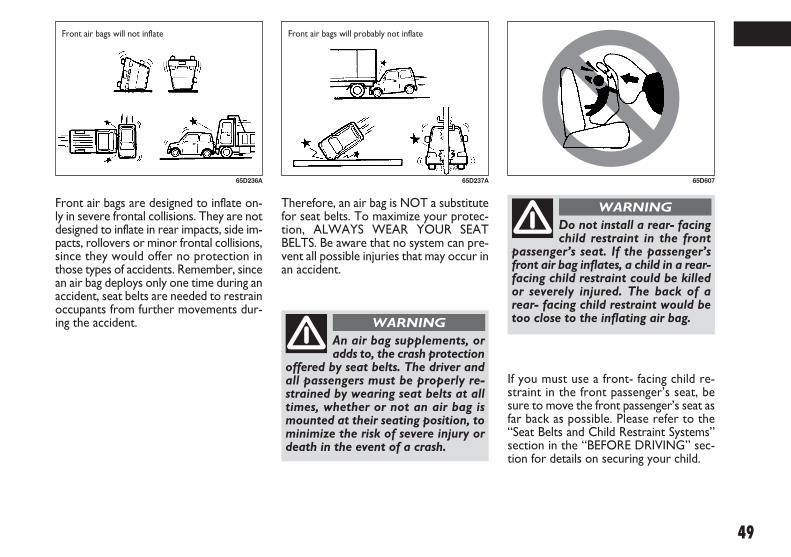
If you must use a front- facing child re-straint in the front passenger’s seat, besure to move the front passenger’s seat asfar back as possible. Please refer to the“Seat Belts and Child Restraint Systems”section in the “BEFORE DRIVING” sec-tion for details on securing your child.
Front air bags are designed to inflate on-ly in severe frontal collisions. They are notdesigned to inflate in rear impacts, side im-pacts, rollovers or minor frontal collisions,since they would offer no protection inthose types of accidents. Remember, sincean air bag deploys only one time during anaccident, seat belts are needed to restrainoccupants from further movements dur-ing the accident.
65D236A 65D237A
Therefore, an air bag is NOT a substitutefor seat belts. To maximize your protec-tion, ALWAYS WEAR YOUR SEATBELTS. Be aware that no system can pre-vent all possible injuries that may occur inan accident.
An air bag supplements, oradds to, the crash protection
offered by seat belts. The driver andall passengers must be properly re-strained by wearing seat belts at alltimes, whether or not an air bag ismounted at their seating position, tominimize the risk of severe injury ordeath in the event of a crash.
WARNING
Do not install a rear- facingchild restraint in the front
passenger’s seat. If the passenger’sfront air bag inflates, a child in a rear-facing child restraint could be killedor severely injured. The back of arear- facing child restraint would betoo close to the inflating air bag.
WARNING
65D607
Front air bags will not inflate Front air bags will probably not inflate
009-056 SEDICI LUM FL GB 1E 19-06-2009 14:11 Pagina 49

SIDE AIR BAGS AND SIDECURTAIN AIR BAGS (for versions/markets, where provided)
Side air bags (for versions/markets, whereprovided) are located in the part of thefront seatbacks closest to the doors. Thewords “SRS AIRBAG” are molded into theside air bag cover to identify the locationof the side air bags.
Air bag plate
The plate is located on the sun visor.
68KM090 52KM036
AVERTISSEMENTWARNINGADVERTENCIA WARNUNGATTENZIONE WAARSCHUWINGVIGYÁZAT
GB
F
E
D
I
NL
H
DO NOT place rear-facing child seat on this seat with airbag.DEATH OR SERIOUS INJURY can occur.The BACK SEAT with child restraint is the SAFEST place for children.
73K021
50
009-056 SEDICI LUM FL GB 1E 19-06-2009 14:11 Pagina 50

51
Side curtain air bags (for versions/markets,where provided) are located in the rooflining. The words “SRS AIRBAG” aremolded into the pillar to identify the lo-cation of the side curtain air bags.
80JM146
If your vehicle is equippedwith a side air bag, do not in-
stall a child restraint in the front pas-senger’s seat. If the passenger’s sideair bag inflates, a child in a child re-straint could be injured.
WARNING
80JM032
Side collision range
54G027
Side air bags and side curtain air bags will not inflate
Never rest head, arms andelbows on the door, on the
windows and in the window bag areato prevent possible injuries during in-flation phase.
WARNINGNever lean head, arms andelbows out of window.
WARNING
009-056 SEDICI LUM FL GB 1E 19-06-2009 14:11 Pagina 51

Side air bags and side curtain air bags aredesigned to inflate only in severe side im-pact collisions. They are not designed toinflate in frontal or rear collisions,rollovers or minor side collisions, sincethey would offer no protection in thosetypes of accidents. Remember, since an airbag deploys only one time during an acci-dent, seat belts are needed to restrain oc-cupants from further movements duringthe accident.
54G028
Side air bags and side curtain air bags will probably not inflate
HOW THE SYSTEM WORKS
In a frontal collision, the crash sensors willdetect rapid deceleration, and if the con-troller judges that the deceleration rep-resents a severe frontal crash, the con-troller will trigger the inflators. If your ve-hicle is equipped with side air bags and sidecurtain air bags, crash sensors will detecta side collision, and if the controller judgesthat the side collision is severe enough, itwill trigger a side inflator. The inflators in-flate the appropriate air bags with nitro-gen or argon gas. The inflated air bags pro-vide a cushion for your head (front air bagsand side curtain air bags only) and upperbody. The air bag inflates and deflates soquickly that you may not even realize thatit has activated. The air bag will neitherhinder your view nor make it harder toexit the vehicle.
Therefore, an air bag is NOT a substitutefor seat belts. To maximize your protec-tion, ALWAYS WEAR YOUR SEATBELTS. Be aware that no system can pre-vent all possible injuries that may occur inan accident.
An air bag supplements, oradds to, the crash protection
offered by seat belts. The driver andall passengers must be properly re-strained by wearing seat belts at alltimes, whether or not an air bag ismounted at their seating position, tominimize the risk of severe injury ordeath in the event of a crash.
WARNING
65D610
52
009-056 SEDICI LUM FL GB 1E 19-06-2009 14:11 Pagina 52

53
54G582
Air bags must inflate quickly and forceful-ly in order to reduce the chance of seri-ous or fatal injuries. However, an un-avoidable consequence of the quick infla-tion is that the air bag may irritate bareskin, such as the facial area against a frontair bag. Also, upon inflation, a loud noisewill occur and some powder and smokewill be released. These conditions are notharmful and do not indicate a fire in thecar. Be aware, however, that some air bagcomponents may be hot for a while afterinflation.
The driver should not leanover the steering wheel. The
front passenger should not rest his orher body against the dashboard, orotherwise get too close to the dash-board. For vehicles with side air bagsand side curtain air bag, occupantsshould not lean on or sleep againstthe door. In these situations, the out-of- position occupant would be tooclose to an inflating air bag, and maysuffer severe injury.Do not attach any objects to, or placeany objects over, the steering wheelor dashboard. Do not place any ob-jects between the air bag and the dri-ver or front passenger. These objectsmay interfere with air bag operationor may be propelled by the air bagin the event of a crash. Either of theseconditions may cause severe injury.For vehicles with side air bags, do notplace seat covers on the front seats,because seat covers could restrict theair bag’s inflation. Also, do not placeany cup holders on the door, as thecup holder could be propelled by theair bag in the event of a crash. Eitherof these conditions may cause severeinjury.
WARNING
A seat belt helps keep you in the properposition for maximum protection when anair bag inflates. Adjust your seat as far backas possible while still maintaining controlof the vehicle. Sit fully back in your seat;sit up straight; do not lean over the steer-ing wheel or dashboard. Front occupantsshould not lean on or sleep against thedoor. Please refer to the “Seat Adjust-ment” section and the “Seat Belts andChild Restraint Systems” section in the“BEFORE DRIVING” section for detailson proper seat and seat belt adjustments.
009-056 SEDICI LUM FL GB 1E 19-06-2009 14:11 Pagina 53

Note that even though your vehicle maybe moderately damaged in a collision, thecollision may not have been severe enoughto trigger the front or side air bags to in-flate. If your vehicle sustains ANY front-end or side damage, have the air bag sys-tem inspected by an authorized Fiat Deal-ership to ensure it is in proper workingorder.
Your vehicle is equipped with a diagnosticmodule which records information aboutthe air bag system if the air bags deployin a crash. The module records informa-tion about overall system status, whichsensors activated the deployment.
SERVICING THE AIR BAGSYSTEM
If the air bags inflate, have the air bags andrelated components replaced by an au-thorized Fiat Dealership as soon as pos-sible.
If your vehicle ever gets in deep water andthe driver’s floor is submerged, the air bagcontroller could be damaged. If it does,have the air bag system inspected by theFiat Dealership as soon as possible.
Special procedures are required for ser-vicing or replacing an air bag. For that rea-son, only an authorized Fiat Dealershipshould be allowed to service or replaceyour air bags. Please remind anyone whoservices your Fiat that it has air bags.
Service on or around air bag componentsor wiring must be performed only by anauthorized Fiat Dealership. Improper ser-vice could result in unintended air bag de-ployment or could render the air bag in-operative. Either of these two conditionsmay result in severe injury.
To prevent damage or unintended infla-tion of the air bag system, be sure the bat-tery is disconnected and the ignitionswitch has been in the “LOCK” positionfor at least 90 seconds before perform-ing any electrical service work on your Fi-at. Do not touch air bag system compo-nents or wires. The wires are wrappedwith yellow tape or yellow tubing, and thecouplers are yellow for easy identification.
Scrapping a vehicle that has an uninflatedair bag can be hazardous. Ask your FiatDealership, body repair shop or scrapyard for help with disposal.
54
009-056 SEDICI LUM FL GB 1E 19-06-2009 14:11 Pagina 54

55
GENERAL WARNINGS
Never travel with objects onyour lap, in front of your
chest or with a pipe, pencil, etc. be-tween your lips; injury may result inthe event of the air bag being trig-gered.
WARNING
Remember that with the keyengaged and at ON, even if
the engine is not running, the air bagsmay be triggered on a stationary ve-hicle if it is bumped by another mov-ing car. Therefore, never seat childrenon the front seat even when the ve-hicle is stationary. On the other handremember that if the key is at LOCK,no safety system (air bags or preten-sioners) is triggered in the event of animpact; in this case, failure to comeinto action cannot be considered as asign that the system is not workingproperly.
WARNING
If the vehicle has been stolenor an attempt to steal it has
been made, if it has been subjected tovandals or floods, have the air bagsystem checked by Fiat Dealership.
WARNING
Do not wash the seat backrest with pressurised water
or steam (by hand or at automaticseat washing stations).
WARNING
The front air bag is triggeredfor shocks greater in magni-
tude that the pretensioners. For im-pacts between these two thresholds,it is therefore normal that only thepretensioners are triggered.
WARNING
Do not hook rigid objects tothe coat hooks and to the
support handles.
WARNING
009-056 SEDICI LUM FL GB 1E 19-06-2009 14:11 Pagina 55
Page left blank voluntarily.
009-056 SEDICI LUM FL GB 1E 19-06-2009 14:11 Pagina 56

57
SSTTEEEERRIINNGG CCOOLLUUMMNN CCOONNTTRROOLLSS
60G405
IGNITION SWITCH ............................................................ 58
LIGHTING/TURN SIGNAL CONTROL LEVER............ 63
WINDSHIELD WIPER AND WASHER LEVER ............. 65
REAR WINDOW WIPER/WASHER SWITCH (for versions/markets, where provided)........................... 66
TILT STEERING LOCK LEVER (for versions/markets, where provided)........................... 67
REMOTE AUDIO CONTROLS (for versions/markets, where provided)........................... 68
HORN...................................................................................... 68
CRUISE CONTROL (for versions/markets, where provided)........................... 69
2
057-070 SEDICI LUM FL GB 1E 19-06-2009 10:32 Pagina 57

58
IGNITION SWITCH
VEHICLE WITHOUT KEYLESSSTART SYSTEM
The ignition switch has the following fourpositions:
LOCK
This is the normal parking position. It isthe only position in which the key can beremoved.
It locks the ignition, and prevents normaluse of the steering wheel after the key isremoved.
Manual transaxle vehicles
You must push in the key to turn it to the“LOCK” position. It locks the ignition, andprevents normal use of the steering wheelafter the key is removed.
Automatic transaxle vehicles
The gearshift lever must be in the “P”(Park) position to turn the key to the“LOCK” position. It locks the ignition andprevents normal use of the steering wheeland gearshift lever.
65D611
To avoid possible injury, donot operate controls by
reaching through the steering wheel.
WARNING
60G033A
Turn to “LOCK”
Push
60B041A
To release the steering lock, insert the keyand turn it clockwise to one of the otherpositions. If you have trouble turning thekey to unlock the steering, try turning thesteering wheel slightly to the right or leftwhile turning the key.
Manual transaxle
057-070 SEDICI LUM FL GB 1E 19-06-2009 10:32 Pagina 58

59
ACC
Accessories such as the radio can oper-ate, but the engine is off.
ON
This is the normal operating position. All electrical systems are on.
START
This is the position for starting the engineusing the starter motor. The key shouldbe released from this position as soon asthe engine starts.
Ignition key reminder (for versions/markets, where provided)
A buzzer sounds intermittently to remindyou to remove the ignition key if it is inthe ignition switch when the driver’s dooris opened.
If the ignition device is tam-pered with (e.g.: attempted
theft), have it checked over by a FiatDealership as soon as possible.
WARNING
When getting out of the ve-hicle, always remove the key
to prevent any occupants from acci-dentally activating the controls. Re-member to engage the handbrakeand if the vehicle is parked on uphillslope to engage the first gear. If thevehicle is facing downhill, engage thereverse gear. Never leave unsuper-vised children in the vehicle.
WARNING
Never remove the ignitionkey while the vehicle is mov-
ing. The steering wheel would auto-matically lock as soon as you try toturn it. This also applies when the ve-hicle is being towed.
WARNING
It is absolutely forbidden tocarry out whatever after-
market operation involving steeringsystem or steering column modifica-tions (e.g.: installation of anti-theftdevice) that could badly affect per-formance and safety, cause the lapseof warranty and also result in non-compliance of the vehicle with ho-mologation requirements.
WARNING
057-070 SEDICI LUM FL GB 1E 19-06-2009 10:32 Pagina 59

60
❒ If the keyless start system red indicatorlight illuminates, the remote controllermay not be in the vehicle or the batteryof the remote controller may be unre-liable. The red indicator light will turnoff within several seconds after the re-mote controller is returned in the ve-hicle except in the rear luggage area.
When the remote controller is in the ve-hicle except the rear luggage area, you canturn the ignition switch without using anignition key.
NOTE
❒ If the battery of the remote controllerruns down or there are strong radiowaves or noise, the operating rangemay be narrower or the remote con-troller may be inoperative.
❒ If the remote controller is too close tothe door glass, it may not operate.
❒ The ignition switch may not turn whenthe remote controller is on the instru-ment panel, in the glove box, in thedoor pocket, in the sun visor or on thefloor.
VEHICLE WITH KEYLESSSTART SYSTEM
The ignition switch can be operated whenthe remote controller is in the vehicle ex-cept the rear luggage area. To turn theignition switch, push the switch first.
Manual transaxle vehicleYou must push in the ignition switch toturn it from the “LOCK” position to the“ACC” position. To return to the“LOCK” position from the “ACC” posi-tion, turn the ignition switch counter-clockwise while pushing in the switch.
Automatic transaxle vehicleTo turn the ignition switch, push theswitch.
If the keyless start system blue indicatorlight illuminates on the instrument cluster,you can turn the ignition switch. If the redindicator light illuminates, you can not turnthe ignition switch.
NOTE
❒ The ignition switch can be turned to the“ACC” position when the keyless startsystem blue indicator light illuminates.The blue indicator light will illuminatefor several seconds and then turn off toprotect the system. In this case, youmust release the ignition switch onceand push the switch again.
(1)
(2)
(3)
(4)
56KN076 79JF001
057-070 SEDICI LUM FL GB 1E 19-06-2009 10:32 Pagina 60

61
IMPORTANT The remote controller isa sensitive electronic instrument. To avoiddamaging the remote controller:
❒ Do not expose it to impacts, moistureor high temperature such as on thedashboard under direct sunlight.
❒ Keep the remote controller away frommagnetic objects such as a television.
You can also turn the ignition switch byinserting the ignition key into the slot.
If you leave any of the doors open with theignition switch in the “ACC” position fora while (and no key inserted), the enginemay not start when you turn the ignitionswitch to “START”. If the engine does notstart, close all doors completely or turnthe ignition switch back to the “LOCK”position, then start the engine.
The ignition switch has the following fourpositions:
ACC (2)
Accessories such as the radio can oper-ate, but the engine is off.
ON (3)
This is the normal operating position. Allelectrical systems are on.
START (4)
This is the position for starting the engineusing the starter motor. The switch shouldbe released from this position as soon asthe engine starts.
Ignition switch reminder
(When using the keyless start system)
A buzzer sounds intermittently to remindyou to return the ignition switch to the“LOCK” position if it is in the “ACC” po-sition when the driver’s door is opened.
LOCK (1)
This is the normal parking position. It isthe only position in which the key can beremoved. It locks the ignition, and pre-vents normal use of the steering wheel.
If your vehicle is equipped with the auto-matic transaxle key inter lock system, theignition switch can be turned to the“LOCK” position only when the gearshiftlever is in the “P” (Park) position.
To release the steering lock, turn the ig-nition switch clockwise to one of the oth-er positions. If you have trouble turningthe ignition switch to unlock the steer-ing, try turning the steering wheel slightlyto the right or left while turning theswitch.
Manual transaxle vehicleYou must push in the ignition switch toturn it from the “LOCK” position to the“ACC” position. To return to the“LOCK” position from the “ACC” posi-tion, turn the ignition switch counter-clockwise while pushing in the switch.
Automatic transaxle vehicleTo turn the ignition switch, push theswitch.
057-070 SEDICI LUM FL GB 1E 19-06-2009 10:32 Pagina 61

62
81A297S
(1)
80JM139
Never return the ignitionswitch to the “LOCK” posi-
tion and remove the ignition keywhile the vehicle is moving. The steer-ing wheel will lock and you will not beable to steer the vehicle.Always return the ignition switch tothe “LOCK” position and remove theignition key when leaving the vehicleeven if a short time. Also do not leavechildren alone in a parked vehicle.Unattended children could cause ac-cidental movement of the vehicle orcould tamper with power windows orpower sunroof. They also could suf-fer from heat stroke in warm or hotweather. These could result in severeinjury or even death.
WARNING
IMPORTANT
❒ Do not use the starter motor for morethan 15 seconds at a time. For dieselengine model, do not use the startermotor for more than 30 seconds at atime. If the engine does not start, wait15 seconds before trying again. If theengine does not start after several at-tempts, check the fuel and ignition sys-tems or consult your Fiat Dealership.
❒ Do not leave the ignition switch in the“ON” position if the engine is not run-ning as the battery will discharge.You can also turn the ignition switch by
inserting the ignition key into the slot.
The ignition switch cap (1) is installed tomake the ignition switch turn easily.
If you use the ignition key to turn the ig-nition switch, remove the cap (1) by pinch-ing both side of the cap and pull it out.
NOTE If you remove the cap, be carefulnot to lose it.
Ignition key reminder
(When using the ignition key)
A buzzer sounds intermittently to remindyou to remove the ignition key if it is inthe ignition switch when the driver’s dooris opened.
057-070 SEDICI LUM FL GB 1E 19-06-2009 10:32 Pagina 62

63
Lights “On” reminder (for versions/markets, where provided)
A buzzer/chime sounds to remind you toturn off the lights if they are left on whenthe ignition key is removed and the dri-ver’s door is opened.
Day time running light control (for versions/markets, where provided)
When the engine is started, this systemturns on all lights. But this control is can-celed when the light control lever isturned to any position other than “OFF”.
LIGHTING/TURNSIGNAL CONTROLLEVER
LIGHTING OPERATION
To turn the lights on or off, twist the knobon the end of the lever. There are threepositions:
OFF (1) all lights are off.
3 (2) Front parking lights, tail-lights, li-cense plate light and instrument lights areon, but headlights are off.
1 (3) Front parking lights, tail-lights, li-cense plate light, instrument lights andhead lights are on.
With the headlights on, push the lever for-ward to switch to the high beams (mainbeams) or pull the lever toward you toswitch to the low beams. When the highbeams (main beams) are on, a light on theinstrument panel will come on. To mo-mentarily activate the high beams (mainbeams) as a passing signal, pull the leverslightly toward you and release it whenyou have completed the signal.
(1)
(2)
(3)
78K068 78K069
057-070 SEDICI LUM FL GB 1E 19-06-2009 10:32 Pagina 63

64
TURN SIGNAL OPERATION
With the ignition switch in the “ON” po-sition, move the lever up or down to ac-tivate the right or left turn signals.
Normal turn signal
Move the lever all the way upward ordownward to signal. When the turn iscompleted, the signal will cancel and thelever will return to its normal position.
Lane change signal
Some times, such as when changing lanes,the steering wheel is not turned farenough to cancel the turn signal. For con-venience, you can flash the turn signal bymoving the lever part way and holding itthere. The lever will return to its normalposition when you release it.
REAR FOG LIGHT SWITCH
To turn the rear fog light on, twist theknob as shown in the illustration with thehead light switch in the third position.When the rear fog light is on, an indicatorlight on the instrument cluster will comeon. Do not turn the rear fog light switchunless the head light switch is in the thirdposition.
NOTE When the head light switch is re-turned to the “OFF” position, the rear foglight switch will be canceled automatically.
78K070 78K071 78K072
057-070 SEDICI LUM FL GB 1E 19-06-2009 10:32 Pagina 64

65
If the lever is equipped with the “INTTIME” control, turn the control forwardor rearward to adjust the intermittentwiper operation to the desired interval.
WINDSHIELD WASHER
To spray windshield washer fluid, pull thelever toward you. The windshield wiperswill automatically turn on at low speed ifthey are not already on and the “INT” po-sition is equipped.
WINDSHIELD WIPERAND WASHER LEVER
WINDSHIELD WIPERS
To turn the windshield wipers on, movethe lever down to one of the three op-erating positions. In the “INT” position(for versions/markets, where provided),the wipers operate intermittently. The“INT” position is very convenient for dri-ving in mist or light rain. In the “LO” po-sition, the wipers operate at a steady lowspeed. In the “HI” position, the wipers op-erate at a steady high speed. To turn offthe wipers, move the lever back to the“OFF” position.
Move the lever up and hold it to the“MIST” position, the windshield wiperswill turn on continuously at low speed.
IMPORTANT Never use the windowwiper to remove ice or snow from thewindscreen. In these conditions, the wiperis submitted to excessive effort that re-sults in motor protection cutting in andwiper operation inhibition for few secondsas a consequence. If operation is not re-stored (also after restarting the vehicle bythe ignition key) contact Fiat Dealership.
MIST
OFF
INT
LO
HI
63J301
63J302
63J303
To prevent windshield icing incold weather, turn on the de-
froster to heat the windshield beforeand during windshield washer use.Do not use radiator antifreeze in thewindshield washer reservoir. It can se-verely impair visibility when sprayedon the windshield, and can also dam-age your vehicle’s paint.
WARNING
057-070 SEDICI LUM FL GB 1E 19-06-2009 10:32 Pagina 65

66
REAR WINDOWWIPER/WASHERSWITCH(for versions/markets, where provided)
To turn the rear wiper on, twist the rearwiper switch on the end of the lever for-ward to the “ON” position. If your vehi-cle is equipped the “INT” position, therear wiper operates intermittently whenyou twist the switch forward to the “INT”position. To turn the rear wiper off, twistthe switch rearward to the “OFF” posi-tion.
With the rear wiper in the “OFF” posi-tion, twist the switch rearward and holdit there to spray window washer fluid.
With the rear wiper in the “ON” position,turn the switch forward and hold it thereto spray window washer fluid.
IMPORTANT Clear ice or snow from therear window and rear wiper blade beforeusing the rear wiper. Accumulated ice orsnow could prevent the wiper blade frommoving, causing damage to the wiper mo-tor.
63J304
WiperWasher
Intermittent wiper
IMPORTANT To help prevent damage tothe windshield wiper and washer systemcomponents, you should take the follow-ing precautions:
❒ Do not continue to hold in the leverwhen there is no windshield washer flu-id being sprayed or the washer motorcan be damaged.
❒ Do not attempt to remove dirt from adry windshield with the wipers or youcan damage the windshield and thewiper blades. Always wet the wind-shield with washer fluid before oper-ating the wipers.
❒ Clear ice or packed snow from thewiper blades before using the wipers.
❒ Check the washer fluid level regularly.Check it often when the weather is bad.
❒ Only fill the washer fluid reservoir 3/4 full during cold weather to allowroom for expansion if the temperaturefalls low enough to freeze the solution.
057-070 SEDICI LUM FL GB 1E 19-06-2009 10:32 Pagina 66

67
TILT STEERING LOCKLEVER(for versions/markets, where provided)
The lock lever is located under the steer-ing column. To adjust the steering wheelheight:
❒ Pull up the lock lever to unlock thesteering column.
❒ Adjust the steering wheel to the de-sired height and lock the steering col-umn by push down the lock lever.
❒ Try moving the steering wheel up anddown to make sure it is securely lockedin position.
63J026
UNLOCKLOCK
Never attempt to adjust thesteering wheel height while
the vehicle is moving or you could losecontrol of the vehicle.
WARNING
Any adjustment of the steer-ing wheel position must be
carried out only with the vehicle sta-tionary and the engine turned off.
WARNING
It is absolutely forbidden tocarry out whatever after-
market operation involving steeringsystem or steering column modifica-tions (e.g.: installation of anti-theftdevice) that could badly affect per-formance and safety, cause the lapseof warranty and also result in non-compliance of the vehicle with ho-mologation requirements.
WARNING
057-070 SEDICI LUM FL GB 1E 19-06-2009 10:32 Pagina 67

68
HORN
Press the horn button of the steeringwheel to sound the horn. The horn willsound with the ignition switch in any po-sition.
63J307
REMOTE AUDIOCONTROLS(for versions/markets, where provided)
You can control basic functions of the au-dio system with the switches on the steer-ing wheel.
For details, refer to “Audio Systems” inthe “INSTRUMENT PANEL” section.
80JM014
057-070 SEDICI LUM FL GB 1E 19-06-2009 17:04 Pagina 68

69
(2)(1)
(4) (3)
(6)(5)
FSUV1650
CRUISE CONTROL(for versions/markets, where provided)
Cruise Control is an electronic device toassist driving, which makes it possible tomaintain the vehicle at the desired speedwithout the need to press the accelerator.The device must only be used in particu-lar safety conditions, at a speed above 40km/h (25 mph), on long stretches of strai-ght, dry road with little change in speed(e.g. motorways). Therefore it is not re-commended to use this device on extra-urban roads with traffic. Do not use it incities.
CONTROLS
1. MAIN button (ON: device enabled;OFF: device disabled)
2. RES/ACC button (call up stored speed,increase set speed)
3. SET/COAST button (store speed, de-crease set speed)
4. CANCEL button (switch off device)
5. CRUISE warning light (device enabled)
6. SET warning light (device working)
ENABLING OF THE DEVICE
To enable the device and prepare it foroperation, press the “MAIN” button (1).
The “CRUISE” warning light on the in-strument panel comes on to signal that thedevice has been enabled. The warning li-ght remains on until the device is disabled.
NOTE
❒ In models with a manual gearbox, it isrecommended to use the device only athigh gears (4th, 5th of 6th).
❒ When travelling downhill with the de-vice engaged, the vehicle speed may sli-ghtly exceed the stored one.
STORAGE OF VEHICLE SPEED
In order to store a speed and activateCruise Control, follow these steps.
❒ Enable the device and press the“MAIN” button (1).
❒ Press the accelerator, bringing the vehi-cle up to the desired speed.
❒ Press the “SET/COAST” button (3):vehicle speed is stored and so it is pos-sible to release the accelerator.
NOTE If required (e.g. during overtaking),it's possible to momentarily increase thespeed of the vehicle by pushing the acce-lerator. The vehicle will return to the pre-viously set speed when the pedal is relea-sed.
RESETTING STORED SPEED
If the device is disengaged for one of thefollowing reasons:
❒ pressing the brake pedal;
❒ pressing the clutch (on vehicles withmanual gearbox);
❒ pressing the “CANCEL” button (4);
057-070 SEDICI LUM FL GB 1E 19-06-2009 10:32 Pagina 69

70
❒ following ESP® system intervention (forversions/markets, where provided),
to reset the stored speed, follow thesesteps.
❒ Accelerate gently, bringing the vehicleclose to the stored speed.
❒ Engage the gear selected at the time theprevious speed was stored.
❒ Press the “RES/ACC” button (2).
INCREASE IN STORED SPEED
When Cruise Control is operating, thereare two ways to increase the storedspeed:
❒ by pressing the accelerator and thenstoring the new speed reached,
or
❒ by pressing the “RES/ACC” button (2).Each time the button is pressed, thiscorresponds to a constant increase inspeed, while holding the button downincreases the speed in a continuousmanner.
REDUCTION OF STOREDSPEED
When Cruise Control is operating, thereare two ways to reduce the stored speed:
❒ by disengaging the device and then sto-ring the new speed,
or
❒ by pressing the “SET/COAST” button(3). Each time the button is pressed, thiscorresponds to a constant decrease inspeed, while holding the button downdecreases the speed in a continuousmanner.
DISENGAGING OF THE DEVICE
The device is disengaged in one of the fol-lowing cases:
❒ pressing the “CANCEL” button (4);
❒ pressing the brake pedal;
❒ pressing the clutch (on vehicles withmanual gearbox);
❒ switching off the engine (starter swit-ch set to “OFF”);
❒ by disabling the system (“MAIN” but-ton (1) set to “OFF”);
❒ when the vehicle speed is reduced byapproximately 20% compared with theset speed;
❒ when the vehicle speed is below 36km/h (22 mph);
❒ in the event of ESP® system interven-tion (where provided);
❒ in the event of system breakdown.
NOTE By pressing the accelerator, the sy-stem is not actually disengaged, but the re-quired acceleration takes precedence overmaintaining the stored speed: Cruise Con-trol, however, remains enabled and willreturn to the previous condition once theaccelerator has been released, without ha-ving to press the “RES/ACC” button (2).
IMPORTANT When travelling with thedevice on, never set the gearshift lever toneutral.
IMPORTANT In the event of malfunctionor failure, disable the device (“MAIN” but-ton (1) set to “OFF”) and see your FiatDealership.
057-070 SEDICI LUM FL GB 1E 19-06-2009 10:32 Pagina 70

71
IINNSSTTRRUUMMEENNTT PPAANNEELL
60G406
INSTRUMENT PANEL......................................................... 72
INSTRUMENT CLUSTER.................................................... 73
WARNING AND INDICATOR LIGHTS........................ 74
SPEEDOMETER ..................................................................... 83
TACHOMETER ..................................................................... 84
FUEL GAUGE......................................................................... 84
TEMPERATURE GAUGE/OVERHEAT INDICATOR LIGHT (for Diesel Engine Model) ...................................... 85
INFORMATION DISPLAY.................................................. 85
HAZARD WARNING SWITCH....................................... 91
FRONT FOG LIGHT SWITCH (for versions/markets, where provided)........................... 91
“ESP OFF” SWITCH (for versions/markets, where provided)........................... 92
2WD/ 4WD SWITCH (for versions/markets, where provided)........................... 92
HEATED REAR WINDOW AND HEATED OUTSIDEREARVIEW MIRRORS SWITCH (for versions/markets, where provided)........................... 93
HEADLIGHT LEVELING SWITCH (for versions/markets, where provided)........................... 94
GLOVE BOX.......................................................................... 94
CIGARETTE LIGHTER AND ASHTRAY (for versions/markets, where provided)........................... 95
THEFT DETERRENT LIGHT.............................................. 95
HEATING AND AIR CONDITIONING SYSTEM ........ 96
HEATING SYSTEM (for versions/markets, where provided)........................... 97
MANUAL HEATING AND AIR CONDITIONING SYSTEM (for versions/markets, where provided)......... 100
AUTOMATIC HEATING AND AIR CONDITIONING SYSTEM (Climate Control) (for versions/markets, where provided)........................... 104
AUDIO SYSTEMS.................................................................. 110
3
071-128 SEDICI LUM FL GB 1E 19-06-2009 12:05 Pagina 71

72
INSTRUMENT PANEL
1. Instrument cluster
2. Ignition switch
3. Lighting switch/Turn signal and dimmer switch
4. Windshield wiper and washerswitch/ Rear window wiper andwasher switch (for versions/markets, where provided)
5. Hazard warning switch
6. Other switches (for versions/markets, where provided)
7. Heater control panel
8. Audio (for versions/markets, whereprovided)
9. Cigarette lighter
10. Hood release
11. Center ventilator
12. Side ventilator
13. Side defroster
14. Glove box
15. Fuse box
16. Air bag (for versions/markets,where provided)
3
15
16 1 4 511 8 16
2 7 9 14106
4
10
163 18 5 1116
13 13 12 131312
13 13 12 131312
714 152 69
79JM021
Right-hand drive
Left-hand drive
071-128 SEDICI LUM FL GB 1E 19-06-2009 12:05 Pagina 72

73
INSTRUMENT CLUSTER
1. Speedometer
2. Tachometer
3. Fuel gauge
4. Temperature gauge
5. Information display
6. Trip meter selector knob
7. Indicator selector knob
8. Warning and indicator lights
5 7 88 6
12 384
79JF018
071-128 SEDICI LUM FL GB 1E 19-06-2009 12:05 Pagina 73

74
The light should go out after starting theengine and fully releasing the parkingbrake, if the fluid level in the brake fluidreservoir is adequate.
The light also comes on together with theABS warning light when the rear brakeforce control function (Proportioningvalve function) of the ABS system fails.
If the brake system warning light comeson while you are driving the vehicle, it maymean that there is something wrong withthe vehicle’s brake system. If this happens,you should:
❒ Pull off the road and stop carefully.
❒ Test the brakes by carefully starting andstopping at the side of the road.
– If you determine that it is safe, drivecarefully at low speed to the near-est dealer for repairs, or
WARNING ANDINDICATOR LIGHTS
BRAKE SYSTEM WARNINGLIGHT
65D477
For working check of this light, there arefollowing three different type operationsdepending on the vehicle’s specification.
❒ The light comes on briefly when the ig-nition switch is turned to the “ON”and/or “START” position.
❒ The light comes on when the parkingbrake is engaged with the ignitionswitch in the “ON” position.
❒ The light comes on when under eitheror both of above two conditions.
The light also comes on when the fluid inthe brake fluid reservoir falls below thespecified level.
Remember that stopping dis-tance may be longer, you
may have to push harder on the ped-al, and the pedal may go down far-ther than normal.
WARNING
If any of the following con-ditions occur, you should im-
mediately ask your Fiat Dealership toinspect the brake system.If the brake system warning light doesnot go out after the engine has beenstarted and the parking brake hasbeen fully released.If the brake system warning light doesnot come on when the ignition switchis turned to the “ON” or “START”position.If the brake system warning lightcomes on at any time during vehicleoperation.
WARNING
– Have the vehicle towed to the nearestdealer for repairs.
NOTE Because the disc brake system isselfadjusting, the fluid level will drop as thebrake pads become worn. Replenishingthe brake fluid reservoir is considerednormal periodic maintenance.
071-128 SEDICI LUM FL GB 1E 19-06-2009 12:05 Pagina 74

75
system. If one of these happens, have thesystem inspected by your Fiat Dealership.
If the ABS becomes inoperative, the brakesystem will function as an ordinary brakesystem that does not have this ABS sys-tem.
For details of ABS system, refer to “An-ti-Lock Brake System (ABS)” in the “OP-ERATING YOUR VEHICLE” section.
ANTI-LOCK BRAKE SYSTEM(ABS) WARNING LIGHT
65D529
52KM133
When the ignition switch is turned to the“ON” position, the light comes on brieflyso you can check that the light is working.
If the light stays on, or comes on when dri-ving, there may be something wrong withthe ABS.
If this happens:
❒ Pull off the road and stop carefully.
❒ Turn the ignition switch to “LOCK”and then start the engine again.
If the warning light comes on briefly thenturns off, the system is normal. If the warn-ing light still stays on, the system will besomething wrong.
If the light and the brake system warninglight stay on, or come on simultaneouslywhen driving, your ABS system isequipped with the rear brake force con-trol function (Proportioning valve func-tion) and there may be something wrongwith both the rear brake force controlfunction and anti-lock function of the ABS
SLIP INDICATOR LIGHT (for versions/markets, where provided)
ESP® is a registered trademark of DaimlerAG.
This light blinks 5 times per second whenone of the ESP® systems other than ABSis activated. If this light blinks, drive care-fully.
When the ignition switch is turned to the“ON” position, the light comes on brieflyso you can check that the light is working.If the light stays on, or comes on when dri-ving and remains on, there may be some-thing wrong with the ESP® systems (otherthan ABS). You should have the system in-spected by your FIAT Dealership.
NOTE When you disconnect and re- con-nect the battery, ESP® system functions oth-er than ABS will be deactivated and the slipindicator light will blink 1 time per second.For details on how to reactive the ESP® sys-tems, refer to “SLIP Indicator Light” in the“OPERATING YOUR VEHICLE” section.
For details of the ESP® systems, refer to“Electronic Stability Program (ESP® )” in the“OPERATING YOUR VEHICLE” section.
The ESP® systems cannotprevent accidents. Always
drive carefully.
WARNING
071-128 SEDICI LUM FL GB 1E 19-06-2009 12:05 Pagina 75

76
Check the oil level and add oil if necessary.If there is enough oil, the lubrication sys-tem should be inspected by your Fiat Deal-ership before you drive the vehicle again.IMPORTANT❒ If you operate the engine with this light
on, severe engine damage can result.❒ Do not rely on the Oil Pressure Light
to indicate the need to add oil. Besure to periodically check the engineoil level.
50G051A
66J032
This light comes on when the ignitionswitch is turned to the “ON” position, andgoes out when the engine is started. Thelight will come on and remain on if thereis insufficient oil pressure.
If the warning light vturns on when the vehicle is
travelling stop the engine immedi-ately and contact a Fiat Dealership.
WARNING
OIL PRESSURE LIGHT
OIL SERVICE LIGHT(For Diesel Engine Model)
79JM007
Your vehicle has the oil life monitoringsystem that let you know when to changethe engine oil and filter.
This light comes on for several secondswhen the ignition switch is turned to the“ON” position so you can check that lightis working.
When the ignition switch is turned to the“ON” position, the light comes on brieflyso you can check that the light is working.If the light stays on, or comes on when dri-ving, there may be something wrong withthe ESP® systems (other than ABS). Youshould have the system inspected by anauthorized FIAT dealer.
For details of the ESP® systems, refer to“Electronic Stability Program (ESP®)” in the“OPERATING YOUR VEHICLE” section.
“ESP OFF” INDICATOR LIGHT(for versions/markets, where provided)
When the ignition switch is turned to the“ON” position, this light comes on brieflyso you can check that the light is working.
When the “ESP OFF” switch is pushed toturn off the ESP® systems (other thanABS), the “ESP OFF” light comes on andstays on.
For details of the ESP®systems, refer to“Electronic Stability Program (ESP®)” inthe “OPERATING YOUR VEHICLE” sec-tion.66J031
“ESP” WARNING LIGHT (Electronic Stability Program) (for versions/markets, where provided)
071-128 SEDICI LUM FL GB 1E 19-06-2009 12:05 Pagina 76

77
SEAT BELT REMINDER LIGHT(for versions/markets, where provided)
60G049
When the driver doesn’t buckle his or herseat belt, this light will come on.
63J030
This light blinks or comes on for severalseconds when the ignition switch is turnedto the “ON” position so you can check ifthe light is working.
The light will come on and stay on if thereis a problem in the air bag system or theseat belt pretensioner system (for ver-sions/markets, where provided).
CHARGING LIGHT
50G052A
This light comes on when the ignitionswitch is turned to the “ON” position, andgoes out when the engine is started. Thelight will come on and remain on if thereis something wrong with the battery charg-ing system. If the light comes on when theengine is running, the charging systemshould be inspected immediately by yourFiat Dealership.
For details about the seat belt reminder, re-fer to “Seat Belts and Child Restraint Sys-tems” in the “BEFORE DRIVING” section.
“AIR BAG” LIGHT (for versions/markets, where provided)
Change the engine oil andfilter at the first blink of the
light. If you keep operating the engineafter the light blinks, severe enginedamage can result.
WARNING
If this light comes on when the engine isrunning, you should change the engine oiland oil filter immediately since the moni-toring system has calculated that oil lifehas been diminished by detecting a dete-rioration, increase or decrease of engineoil.
When the engine oil and oil filter arechanged, and the oil life monitoring sys-tem is reset, this light will go out. For de-tails on how to change the engine oil, re-fer to “Changing Engine Oil and Filter” in“INSPECTION AND MAINTENANCE”section. Whenever the engine oil ischanged, the light must be reset to mon-itor the next oil change timing properly.To reset the light, consult your Fiat Deal-ership.
If the “AIR BAG” light doesnot blink or come on briefly
when the ignition switch is turned tothe “ON” position, stays on for morethan 10 seconds, or comes on whiledriving, the air bag system or the seatbelt pretensioner system (for ver-sions/markets, where provided) maynot work properly. Have both systemsinspected by an authorized Fiat Deal-ership.
WARNING
071-128 SEDICI LUM FL GB 1E 19-06-2009 12:05 Pagina 77

78
SERVICE VEHICLE SOON (SVS)LIGHT (for Diesel Engine Model)
84E034
When the ignition switch is turned to the“ON” position, this light comes on brieflyto let you know the light is working.
If this light blinks with the ignition switchturned “ON”, the engine will not start.
NOTE If this light blinks, turn the ignitionswitch to the “LOCK” position, then turnit back to the “ON” position. If the light stillblinks with the ignition switch turned to the“ON” position, there may be somethingwrong with the immobilizer system. Ask toyou Fiat Dealership to inspect the system.
MALFUNCTION INDICATORLIGHT
65D530
Your vehicle has a computer-controlledemission control system. A malfunction in-dicator light is provided on the instrumentcluster to indicate when it is necessary tohave the emission control system serviced.The malfunction indicator light comes onwhen the ignition switch is turned to the“ON” position to let you know the lightis working and goes out when the engineis started.
If the malfunction indicator light comes onor blinks when the engine is running, ser-vice to the emission control system is nec-essary. Bring the vehicle to your FIATDealership to have the emission controlsystem serviced right away and avoid hardacceleration until the service is performed.
IMPORTANT Continuing to drive the ve-hicle when the malfunction indicator lightis on or blinking can cause permanentdamage to the vehicle’s emission controlsystem, and can affect fuel economy anddriveability.
TRANSAXLE WARNING LIGHT(for versions/markets, where provided)
81A262
This light comes on for several secondswhen the ignition switch is turned to the“ON” position so you can check the lightis working. If this light comes on, there isthe problem with the transaxle system.Ask your Fiat Dealership to have the sys-tem inspected.
071-128 SEDICI LUM FL GB 1E 19-06-2009 12:05 Pagina 78

79
FUEL FILTER WARNING LIGHT(for Diesel Engine Model)
60A541
This light comes on for several secondswhen the ignition switch is turned to the“ON” position so you can check that lightis working.
If the light comes on when driving, thereis a possibility to have water in the fuelfilter. Drain water as soon as possible. Fordetails of draining water, refer to “Fuel Fil-ter” in the “INSPECTION AND MAIN-TENANCE” section.
IMPORTANT The presence of water inthe fuel circuit may cause serious damageto the entire injection system and causeirregular engine operation. If the warninglight turns on contact Fiat Dealership assoon as possible to have the system re-lieved. If the above indications come onimmediately after refuelling, water hasprobably been poured into the tank: turnthe engine off immediately and contact Fiat Dealership.
FIAT CODE SYSTEM LIGHT (IMMOBILIZER) (for versions/markets, where provided)
65D239
When the ignition switch is turned to the“ON” position, this light comes on to letyou know the light is working.
If this light blinks with the ignition switchturned to “ON”, the engine will not start.
NOTE If this light blinks, turn the ignitionswitch to the “LOCK” position, then turnit back to the “ON” position. If the lightstill blinks with the ignition switch turnedto the “ON” position, there may be some-thing wrong with the immobilizer system. Ask to you Fiat Dealership to inspect thesystem.
54G345
OVERHEAT INDICATOR LIGHT(for Diesel Engine Model)
This light comes on for several secondswhen the ignition switch is turned to the“ON” position so you can check that lightis working.
If this light comes on while driving, it maymean engine overheat. Refer to “Tem-perature Gauge/Overheat Indicator Light”section.
GLOW PLUG INDICATOR LIGHT(for Diesel Engine Model)
60A534
If the coolant temperature is cool enough,this light comes on when the ignitionswitch is turned on and goes out when theglow plug is heated enough for enginestarting.
071-128 SEDICI LUM FL GB 1E 19-06-2009 12:05 Pagina 79

80
79J039
This light comes on when the ignitionswitch is turned to the “ON” position, andgoes out when the engine is started.
If this light comes on while driving, thepower steering system may not workproperly. Have the system inspected byyour Fiat Dealership.
NOTE If the power steering system doesnot work properly, you will feel heavierto steer but you still will be able to steer.
ELECTRIC POWER STEERINGLIGHT (for versions/markets, where provided)
LOW FUEL WARNING LIGHT
54G391
This light remains on until all doors (in-cluding the rear door) are completelyclosed.
If any door (including the tailgate) is openwhen the vehicle is moving, a ding soundsto remind you to close all doors com-pletely.
54G343
If this light comes on, fill the fuel tank im-mediately.
OPEN DOOR WARNING LIGHT When this light comes on, a ding soundsonce to remind you to fill the fuel. If youdo not fill the fuel, a ding sounds everytime when the ignition switch is turned to“ON”.
NOTE The activation point of this lightvaries depending on road conditions (forexample, slope or curve) and driving con-ditions because of fuel moving in the tank.
DIESEL PARTICULATE FILTERWARNING LIGHT (for Diesel Engine Model)
64J244
This light comes on for several secondswhen the ignition switch is turned to the“ON” position so you can check that lightis working.
If the light comes on when driving, thediesel particulate filter is nearly clogged.To regenerate the diesel particulate filter,you must drive the vehicle until the lightgoes out, at a speed of 50 km/h (31 mph)or higher for a while (max. 30 minutes de-pending on the vehicle speed).
If you drive your vehicle until the light goesout, the regeneration of the diesel partic-ulate filter will be completed.
For details, refer to “Diesel Particulate Fil-ter” in the “OPERATING YOUR VEHI-CLE” section.
071-128 SEDICI LUM FL GB 1E 19-06-2009 12:05 Pagina 80

81
MAIN BEAM (HIGH BEAM)INDICATOR LIGHT
50G055
64J045
When you turn on the left or right turnsignals, the corresponding green arrow onthe instrument cluster will flash along withthe respective turn signal lights. When youturn on the hazard warning switch, botharrows will flash along with all of the turnsignal lights.
50G056
This indicator comes on when headlightmain beams (high beams) are turned on.
TURN SIGNAL INDICATORSKEYLESS START SYSTEMINDICATOR LIGHT (for versions/markets, where provided)
80JM122
When you push the ignition switch for ve-hicle with the keyless start system, thislight will come on in blue or red. If thislight comes on in blue, you can turn theignition switch without using an ignitionkey. If this light comes on in red, you cannot turn the ignition switch without us-ing an ignition key. For details, refer to “Ig-nition Switch” in the “STEERING COL-UMN CONTROLS” section.
If this light blinks in red, it reminds you thatthe remote controller is not in the vehi-cle. For details, refer to “Keyless Start Sys-tem” in the “BEFORE DRIVING” section.
REAR FOG LIGHT INDICATORLIGHT (for versions/markets, where provided)
54G491
The rear fog light indicator light comes onwhen the rear fog light operates.
ILLUMINATION INDICATORLIGHT
This indicator light comes on while the po-sition lights, tail light and/or the headlightsare on.
071-128 SEDICI LUM FL GB 1E 19-06-2009 12:05 Pagina 81

82
For details, refer to “Using the 2WD/4WD Switch” in the “OPERATINGYOUR VEHICLE” section.
NOTE If you restart the engine, the lightwill stop blinking temporarily.
NOTE When the vehicle speed is in-creased, the “4WD LOCK” mode will bechanged to the “4WD AUTO” mode au-tomatically. The “4WD AUTO” indicatorlight will come on and stay on.
4WD LOCK INDICATOR LIGHT(for versions/markets, where provided)
79J100
If the light and the “4WD AUTO” indi-cator light stay on or come on simultane-ously when driving, there may be some-thing wrong with the 4WD system. Havethe system inspected by an authorized Fiat Dealership.
NOTE
❒ When the vehicle speed is increased,the “4WD LOCK” mode will bechanged to the “4WD AUTO” modeautomatically. The “4WD AUTO” in-dicator light will come on and stay on.
❒ When the ignition switch is turned tothe “OFF” position, the “4WD LOCK”mode is canceled.
For details of the “4WD LOCK” mode,refer to “Using the 2WD/4WD Switch”in the “OPERATING YOUR VEHICLE”section.
IMPORTANT Do not operate your vehi-cle in “4WD LOCK” mode on dry hardsurfaces.
When the ignition switch is turned to the“ON” position, this light comes on brieflyso you can check that the light is working.
The light comes on when the 2WD/4WDswitch is changed to the “4WD LOCK”mode from the “4WD AUTO” mode.
79J040
When the ignition switch is turned to the“ON” position, the light comes on brieflyso you can check that the light is working.When the 2WD/4WD switch is in the“4WD AUTO” mode with the ignitionswitch in the “ON” position, the lightcomes on and stays on.
If the light and the “4WD LOCK” indica-tor light stay on or come on simultane-ously when driving, there may be some-thing wrong with the 4WD system. Havethe system inspected by an authorized Fiat Dealership.
If the oil temperature of the parts for4WD system is high, this light will blink.The “4WD AUTO” or “4WD LOCK”mode will be changed to the “2WD”mode automatically to prevent a damageof the parts for 4WD system.
4WD AUTO INDICATOR LIGHT(for versions/markets, where provided)
071-128 SEDICI LUM FL GB 1E 19-06-2009 12:05 Pagina 82

83
SPEEDOMETER
The speedometer indicates vehicle speedin km/h and/or mph.
79JM020
CRUISE CONTROL INDICATOR LIGHT(for versions/markets, where provided)
Cruise Control indicator light on
FSUV1649
FSUV1648
This indicator light comes on, with theignition switch set to “ON”, when Crui-se Control is enabled.
Cruise Control indicator lightworking
With the ignition switch set to “ON” andCruise Control enabled, this indicator lightcomes on when the device is working.
071-128 SEDICI LUM FL GB 1E 19-06-2009 12:05 Pagina 83

84
If the low fuel warning light (1) comes on,fill the fuel tank immediately.
When the low fuel warning light (1) comeson, a ding sounds once to remind you tofill the fuel.
If you do not fill the fuel, a ding soundsevery time when the ignition switch isturned to “ON”.
NOTE The activation point of the low fu-el warning light (1) varies depending onroad conditions (for example, slope orcurve) and driving conditions because offuel moving in the tank.
The mark (2) indicates that the fuel fillerdoor is located on the left side of the ve-hicle.
TACHOMETER
The tachometer indicates engine speed inrevolutions per minute.
IMPORTANT Never drive with the en-gine speed indicator in the red zone or se-vere engine damage can result. Whendownshifting to a lower gear, make surenot to operate with excessive revolutionspeeds of the engine. Refer to “Down-shifting maximum allowable speeds” in the“OPERATING YOUR VEHICLE” section.
NOTE The indicator moves a little de-pending on road conditions (for example,slope or curve) and driving conditions be-cause of fuel moving in the tank.
(2)
(1)
80JM102
79JM001
FUEL GAUGE
When the ignition switch is in the “ON”position, this gauge gives an approximateindication of the amount of fuel in the fu-el tank. “F” stands for full and “E” standsfor empty.
If the indicator gets off the graduation of“E” (not character “E”), refill the tank assoon as possible.
071-128 SEDICI LUM FL GB 1E 19-06-2009 12:05 Pagina 84

85
When the ignition switch is in the “ON”position, this gauge indicates the enginecoolant temperature. Under normal dri-ving conditions, the indicator should staywithin the normal, acceptable temperaturerange between “H” and “C”. If the indi-cator approaches “H” or the overheat in-dicator light (1) (for versions/markets,where provided) comes on, overheatingis indicated. Follow the instructions for en-gine overheating in the “EMERGENCYSERVICE” section.
IMPORTANT Continuing to drive the ve-hicle when engine overheating is indicat-ed can result in severe engine damage.
(1)
79JF007
(1) (2)(3)
(D)
(B)(A)
(C)
(E)
80JM104
TEMPERATURE GAUGE/OVERHEAT INDICATORLIGHT(For Diesel Engine Model)
INFORMATIONDISPLAY
When the ignition switch is in the “ON”position, the information display showsthe following information.
Display (A)Instantaneous fuel consumption
Display (B)Trip meter / Average fuel consumption /Driving range / Thermometer
Display (C)Transaxle selector position indicator (forautomatic transaxle)
Display (D)Odometer/Illumination control setting
Display (E)Clock (for versions/markets, where pro-vided)
80JM081
1. Trip meter selector knob2. Indicator selector knob3. Information display
Instantaneous Fuel Consumption
The display (A) shows instantaneous fuelconsumption with a bar graph only whenthe vehicle is moving.
071-128 SEDICI LUM FL GB 1E 19-06-2009 12:05 Pagina 85

86
Do not attempt to adjust thedisplay while driving.
If you attempt to adjust the displaywhile driving, you could lose controlof the vehicle.
WARNING
NOTE When you reconnect the negative(–) terminal to the battery, the indicationof the instantaneous fuel consumption willbe reinitialized. Change the indicationagain to your preference.
Trip meter / Average FuelConsumption / Driving Range /Thermometer / Oil LifeMonitoring
When the ignition switch is in the “ON”position, the display (B) shows one of thefollowing six indications, trip meter A, tripmeter B, average fuel consumption, dri-ving range, thermometer or oil life moni-toring.
To switch the display indication (B), pushthe trip meter selector knob (1) or the in-dicator selector knob (2) quickly.
80JM105
80JM106
❒ Change the display (B) to the drivingrange by pushing the indicator selec-tor knob (2).
❒ While pushing and holding the trip me-ter selector knob (1), turn the indica-tor selector knob (2) to turn off or onthe indication of instantaneous fuelconsumption.
NOTE
❒ The display does not show the bargraph unless the vehicle is moving.
❒ The indicated maximum value of in-stantaneous fuel consumption is 30.No more than 30 will be indicated onthe display even if the actual instanta-neous fuel consumption is higher.
❒ The indication on the display may bedelayed if fuel consumption is greatlyaffected by driving conditions.
❒ The display shows estimated values.Indications may not be the same as ac-tual values.
❒ You can change the units that instan-taneous fuel consumption is displayedin. Refer to “Average fuel consump-tion” in this section.
You can turn off or on the indication of in-stantaneous fuel consumption accordingto the following instruction.
071-128 SEDICI LUM FL GB 1E 19-06-2009 12:05 Pagina 86

87
a. Trip meter Ab. Trip meter Bc. Average fuel consumptiond. Driving rangee. Thermometerf. Oil life monitoring
(a)
(b)
(c)
(d)
(e)
(f)
79JM009
AS Push the trip meter selector knob (1).
QZ Push the indicator selector knob (2).
Do not attempt to adjust thedisplay while driving.
If you attempt to adjust the displaywhile driving, you could lose controlof the vehicle.
WARNING
NOTE
❒ Indications will change when you pushand release a knob.
❒ The display shows estimated values.Indications may not be the same as ac-tual values.
Trip meter
The trip meter can be used to measurethe distance traveled on short trips or be-tween fuel stops.
You can use the trip meter A or trip me-ter B independently.
To reset the trip meter to zero, push andhold the trip meter selector knob (1) fora while when the display shows the tripmeter.
NOTE The indicated maximum value ofthe trip meter is 9999.9. When you runpast the maximum value, the indicated val-ue will return to 0.0.
Average fuel consumption
If you selected average fuel consumptionthe last time you drove the vehicle, thedisplay shows the last value of average fu-el consumption from previous drivingwhen the ignition switch is turned to the“ON” position. Unless you reset the val-ue of average fuel consumption, the dis-play indicates the value of average fuelconsumption which includes average fuelconsumption during previous driving.
To reset the average fuel consumption tozero, push and hold the indicator selectorknob (2) for a while when the displayshows the average fuel consumption.
NOTE When you reset the indication orreconnect the negative (–) terminal to thebattery, the value of average fuel con-sumption will be shown after driving fora while.
To change the unit of average fuel con-sumption, while pushing and holding thetrip meter selector knob (1), turn the in-dicator selector knob (2).
071-128 SEDICI LUM FL GB 1E 19-06-2009 12:05 Pagina 87

88
Driving range
If you selected driving range the last timeyou drove the vehicle, the display indicates“---” for a few seconds and then indicatesthe current driving range when the igni-tion switch is turned to the “ON” posi-tion.
The driving range shown in the display isthe approximate distance you can driveuntil the fuel gauge indicates “E”, based oncurrent driving conditions.
When the remaining fuel in fuel tankreaches a low level, the display “---” willappear.
If the low fuel warning light comes on, fillthe fuel tank immediately regardless of thevalue of driving range shown in the display.
As the driving range after refueling is cal-culated based on the most recent drivingcondition, the value is different each timeyou refuel.
NOTE If you refuel when the ignitionswitch is in the “ON” position, the drivingrange may not indicate the correct value.
When you reconnect the negative (–) ter-minal to the battery, the value of drivingrange will be shown after driving for awhile.
Thermometer
The thermometer indicates the outsidetemperature.
If the outside temperature nears freezing,the mark (g) will appear on the display.
NOTE The outside temperature indica-tion is not the actual outside temperaturewhen driving at low speed, or whenstopped.
If there is something wrong with the ther-mometer, or just after the ignition switchis turned to the “ON” position, the dis-play may not indicate the outside tem-perature.
The mark (g) will appear whenever theoutside temperature is near freezing, evenif the display does not show the ther-mometer.
To change the unit of temperature, whilepushing and holding the trip meter selec-tor knob (1), turn the indicator selectorknob (2).
(g)
79JM010
80JM137
NOTE Depending on the vehicle’s speci-fication, the fuel consumption units of ini-tial setting are indicated as km/L orL/100km.
NOTE
❒ When you change the units that av-erage fuel consumption is displayed in,the instantaneous fuel consumptionunits will be changed automatically.
❒ When you reconnect the negative (–)terminal to the battery, the unit of theaverage fuel consumption will be reini-tialized. Change the unit again to yourpreference.
071-128 SEDICI LUM FL GB 1E 19-06-2009 12:05 Pagina 88

89
NOTE When you reconnect the negative(–) terminal to the battery, the unit oftemperature will be reinitialized. Changethe unit again to your preference.
Oil life monitoring
The oil life monitoring indicates the re-maining distance until the next timing tochange the engine oil and oil filter. Whenthe remaining distance become close to0 km, you should change the engine oil andoil filter immediately. The oil service lightin the instrument cluster may also comeon to let you know that you should changethe engine oil and oil filter immediately.For details on how to change the engineoil and oil filter, refer to “Changing EngineOil and Filter” in the “INSPECTION ANDMAINTENANCE” section.
Whenever the engine oil and oil filter arechanged, the oil life monitoring must bereset to monitor the next oil and oil fil-ter change timing properly. To reset theindicator, consult your Fiat Dealership.
When the oil life monitoring is reset, theoil life monitoring indicates the remain-ing distance until the next timing to changeengine oil and filter. If the oil service lightwas on, it will go out.
IMPORTANT Change the engine oil andfilter immediately when the remaining dis-tance of the oil life monitoring indicationbecomes close to 0 km. If you keep op-erating the engine with the indicationshows 0 km, severe engine damage can re-sult.
NOTE If the vehicle is usually used undersevere driving conditions, the engine oiland oil filter should be changed more fre-quently regardless the oil life monitoring.Refer to “Maintenance recommended un-der severe driving condition” in the “IN-SPECTION AND MAINTENANCE” sec-tion.
Transaxle selector positionindicator (for automatic transaxle)
When the ignition switch is in the “ON”position, the display (C) indicates the gearposition (h).
For details on how to use the transaxle,refer to “Using the Transaxle” in the “OPERATING YOUR VEHICLE” section.
Odometer / Illumination ControlSetting
When the ignition switch is in the “ON”position, the display (D) shows theodometer.
If you turn the indicator selector knob (2)clockwise or counterclockwise, the dis-play will change to the illumination controlsetting.
Odometer
The odometer records the total distancethe vehicle has been driven.
80JM093
(h)
79JM011
071-128 SEDICI LUM FL GB 1E 19-06-2009 12:05 Pagina 89

90
Do not attempt to adjust thedisplay while driving.
If you attempt to adjust the displaywhile driving, you could lose controlof the vehicle.
WARNING
NOTE❒ If you push the indicator selector knob
or do not turn the knob for more than5 seconds while activating the illumi-nation control, the illumination con-trol will be canceled automatically andthe display (D) will show the odome-ter indication.
❒ You can change the brightness whenthe position lights or headlights are oneven if the ignition switch is in the“ACC” or “LOCK” position.
❒ When you reconnect the negative (–)terminal to the battery, the brightnessof the instrument panel lights will bereinitialized. Readjust the brightnessaccording to your preference.
NOTE If you select the highest brightnesslevel when the position lights or headlightsare on, the instrument panel lights are notdimmed.
Clock (for versions/markets, whereprovided)
When the ignition switch is in the “ON”position, the display (E) shows the time.
80JM039
IMPORTANT Keep track of your odome-ter reading and check the maintenanceschedule regularly for required services.Increased wear or damage to certain partscan result from failure to perform re-quired services at the proper mileage in-tervals.
Illumination control setting
When the ignition switch is turned to the“ON” position, the instrument panel lightscome on.
Your vehicle has a system to automatical-ly dim the brightness of the instrumentpanel lights when the position lights orheadlights are on.
You can change the brightness of the in-strument panel lights regardless ofwhether the position lights or headlightsare off or on.
To increase the brightness of the instru-ment panel lights, turn the indicator se-lector knob (2) clockwise.
To reduce the brightness of the instru-ment panel lights, turn the indicator se-lector knob (2) counterclockwise.
071-128 SEDICI LUM FL GB 1E 19-06-2009 12:05 Pagina 90

91
HAZARD WARNINGSWITCH
Push in the hazard warning switch to ac-tivate the hazard warning lights. All fourturn signal lights and both turn signal in-dicators will flash simultaneously. To turnoff the lights, push the switch again.
Use the hazard warning lights to warn oth-er traffic during emergency parking orwhen your vehicle could otherwise be-come a traffic hazard.
80JM041
Do not attempt to adjust thedisplay while driving.
If you attempt to adjust the displaywhile driving, you could lose controlof the vehicle.
WARNING
To change the time indication:❒ Push the trip meter selector knob (1)
and the indicator selector knob (2) to-gether.
❒ To change the hour indication, turnthe indicator selector knob (2) left orright repeatedly when the hour indi-cation flashes. To change the hour in-dication quickly, turn and hold the in-dicator selector knob (2). To set thehour indication, push the indicator se-lector knob (2) and the minute indi-cation will flash.
❒ To change the minute indication, turnthe indicator selector knob (2) left orright repeatedly when the minute in-dication flashes. To change the minuteindication quickly, turn and hold theindicator selector knob (2). To set theminute indication, push the indicatorselector knob (2).
NOTE When you reconnect the negative(–) terminal to the battery, the clock in-dication will be reinitialized. Change theindication again to your preference.
64J058
FRONT FOG LIGHTSWITCH(for versions/markets, where provided)
The front fog light comes on when the foglight switch is pushed in with the head lightswitch turned to the second and/ or thirdposition. An indicator light above theswitch will be lit when the front fog lightis on.
NOTE In some countries the lighting op-eration may be different from the abovedescription according to local regulations.
071-128 SEDICI LUM FL GB 1E 19-06-2009 12:05 Pagina 91

92
79J177
2WD/4WD SWITCH(for versions/markets, where provided)
The 2WD/4WD switch is located on thecenter console.
For details on how to use the 2WD/4WD switch, refer to “Using the 2WD/4WD Switch” in the “OPERATINGYOUR VEHICLE” section.
79J180
“ESP OFF” SWITCH (for versions/markets, where provided)
ESP® is a registered trademark of DaimlerAG.
The “ESP OFF” switch is located on thecenter console. You can turn the ESP® sys-tems (other than ABS) on or off using thisswitch.
To turn off the ESP® systems (other thanABS), push and hold the “ESP OFF” switchuntil the “ESP OFF” indicator light comeson.
To turn on all of the ESP® systems, pushthe “ESP OFF” switch again. The “ESPOFF” indicator light will go out.
For details of the ESP® systems, refer to“Electronic Stability Program (ESP®)” inthe “OPERATING YOUR VEHICLE” sec-tion.
071-128 SEDICI LUM FL GB 1E 19-06-2009 12:05 Pagina 92

93
HEATED REARWINDOW AND HEATEDOUTSIDE REARVIEWMIRRORS SWITCH (for versions/markets, where provided)
When the rear window is frosted it is suf-ficient, with the engine started, to pressthe button (1) to defrost it.
If the driver’s outside rearview mirror hasthe mark (2), it is also equipped with theheated outside rearview mirrors. Whenyou push the switch (1), both the heatedoutside rearview mirrors and the heatedrear window will operate simultaneously.
An indicator light will be lit when the de-fogger is on. The defogger will work onlywhen the engine is running. To turn off thedefogger, push the switch (1) again.
IMPORTANT The heated rear windowand the heated outside rearview mirrors(for versions/markets, where provided)use a large amount of electricity. Be sureto turn off after the window and mirrorshave become clear.
(1)
80JM042
(1)
80JM043
NOTE❒ The defogger will work only when the
engine is running.❒ The defogger will automatically turn off
after the defogger remains on for 15minutes to prevent discharging of thebattery.
(2)
80JC040
071-128 SEDICI LUM FL GB 1E 19-06-2009 12:05 Pagina 93

94
HEADLIGHT LEVELINGSWITCH(for versions/markets, where provided)
Level the headlight beam according to theload condition of your vehicle by turningthis switch. The chart below shows the ap-propriate switch position for different ve-hicle-load conditions.
Vehicle Load Condition
Driver only
Driver + 1 passenger (in front seat)
Driver + 4 passengers, No cargo
Driver + 4 passengers, cargo added
Driver + full cargo
SwitchPosition
0
0
1
2
3
80JM040
GLOVE BOX
To open the glove box, pull the latchlever. To close it, push the lid until itlatches securely.
Never drive with the glovebox lid open. It could cause
injury if an accident occurs.
WARNING
79J120
071-128 SEDICI LUM FL GB 1E 19-06-2009 12:05 Pagina 94

95
79J045
Front panel ashtray
79J047
Make sure tobacco is fullyextinguished before closing
the ashtrays. Never throw waste inthe ashtrays: it could create a firehazard.
WARNING
CIGARETTE LIGHTERAND ASHTRAY (for versions/markets, where provided)
CIGARETTE LIGHTER
The cigarette lighter will work when theignition switch is in the “ACC” or “ON”position.
To use the cigarette lighter, push it all theway into the receptacle and release it. Itwill automatically heat up and will pop outto its normal position when it is ready foruse.
IMPORTANT To avoid damage to the cig-arette lighter socket, do not use it as oth-er accessories’ power source. Some ac-cessories’ power plug can damage the in-ner mechanism of the cigarette lightersocket.
ASHTRAY (for versions/markets, where provided)
You can fit the ashtray into any of the cupholders on the center console.
THEFT DETERRENT LIGHT
This light will blink with the ignition switchin the “OFF” or “ACC” position. Theblinking light is intended to deter theft byleading others to believe that the vehicleis equipped with a security system.
80JM022
071-128 SEDICI LUM FL GB 1E 19-06-2009 12:05 Pagina 95

HEATING AND AIRCONDITIONINGSYSTEM
There are three types of heating and airconditioning systems as follows:
❒ Heating System
❒ Manual Heating and Air ConditioningSystem
❒ Automatic Heating and Air Condition-ing System (Climate Control)
AIR OUTLET
1. Windshield defroster outlet
2. Side defroster outlet
3. Side outlet
4. Center outlet
5. Floor outlet (for versions/markets,where provided) 80JM044
96
071-128 SEDICI LUM FL GB 1E 19-06-2009 12:05 Pagina 96
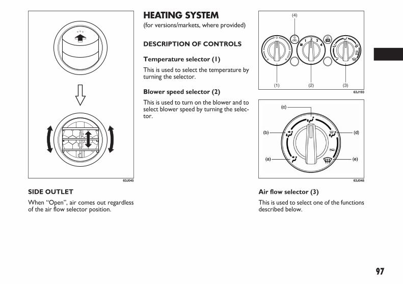
97
HEATING SYSTEM(for versions/markets, where provided)
DESCRIPTION OF CONTROLS
Temperature selector (1)
This is used to select the temperature byturning the selector.
Blower speed selector (2)
This is used to turn on the blower and toselect blower speed by turning the selec-tor.
Air flow selector (3)
This is used to select one of the functionsdescribed below.
SIDE OUTLET
When “Open”, air comes out regardlessof the air flow selector position.
63J045
(1) (2) (3)
(4)
63J193
63J048
071-128 SEDICI LUM FL GB 1E 19-06-2009 12:05 Pagina 97

98
Heat (c)
Temperature-controlled air comes out ofthe floor outlets and the side outlets, al-so comes out of the windshield defrosteroutlets and also comes slightly out of theside defroster outlets.
Defrost (e)
Temperature-controlled air comes out ofthe windshield defroster outlets, the sidedefroster outlets and the side outlets.
Ventilation (a)
Temperature-controlled air comes out ofthe center and side air outlets.
79J065
79J066
Bi- level (b)
Temperature-controlled air comes out ofthe floor outlets and cooler air comes outof the center and side outlets. When thetemperature selector (1) is in the fullyCOLD position or fully HOT position,however, the air from the floor outletsand the air from the center and side out-lets will be the same temperature.
79J067
79J068
Heat & defrost (d)
Temperature-controlled air comes out ofthe floor outlets, the windshield defrosteroutlets, the side defroster outlets and theside outlets.
79J069
(g)(f)
63J047
Air intake selector (4)
This selector is used to select the follow-ing modes.
Fresh Air (f)
When this mode is selected, the indica-tor light will go off and outside air isused.
071-128 SEDICI LUM FL GB 1E 19-06-2009 12:05 Pagina 98

99
Forced ventilation
The control settings are the same as fornatural ventilation except you set theblower speed selector to a position oth-er than “OFF”.
Normal heating (using outside air)
Select “HEAT” and “FRESH AIR”, thetemperature selector to the desired tem-perature position and the blower speedselector to the desired blower speed po-sition. Setting the blower speed selectorto a higher blower speed position in-creases heating efficiency.
Quick heating (using recirculated air)
The control settings are the same as fornormal heating except you select “RE-CIRCULATED AIR”. If you use this heat-ing method for an extended period oftime, the air in the vehicle can becomecontaminated and the windows can be-come misty. Therefore, use this methodonly for quick heating and change to thenormal heating method as soon as possi-ble.
Head cooled/Feet warmed heating
Select “BI-LEVEL” and “FRESH AIR”, thetemperature selector to the desired tem-perature position, and the blower speed se-lector to the desired blower speed posi-tion. Unless the temperature selector is inthe fully COLD position or fully HOT po-sition, the air that comes out of the cen-ter and side outlets will be cooler than theair that comes out of the floor outlets.
Defrosting/Feet warmed heating
Select “HEAT & DEFROST” and “FRESHAIR”, the temperature selector to the de-sired temperature position, and the blow-er speed selector to HIGH. When thewindshield has become clear, set theblower speed selector to the desiredblower speed position.
Defrosting
Select “DEFROST” and “FRESH AIR”, thetemperature selector to the desired tem-perature position (higher temperatureprovides more efficient defrosting), andthe blower speed selector to HIGH.When the windshield has become clear,set the blower speed selector to the de-sired blower speed position.
Recirculated Air (g)
When this mode is selected, the indicatorlight will come on, outside air is shut outand inside air is recirculated. This mode issuitable when driving through dusty orpolluted air such as in a tunnel, or whenattempting to quickly cool down the in-terior.
“FRESH AIR” and “RECIRCULATED AIR”are switched alternately each time the airintake selector is pushed.
NOTE If you select “RECIRCULATEDAIR” for an extended period of time, theair in the vehicle can become contami-nated. Therefore, you should occasional-ly select “FRESH AIR”.
SYSTEM OPERATINGINSTRUCTIONS
Natural ventilation
Select “VENTILATION” and “FRESHAIR”, the temperature selector to the de-sired temperature position, and the blow-er speed selector to “OFF”. Fresh air willflow through the vehicle during driving.
071-128 SEDICI LUM FL GB 1E 19-06-2009 12:05 Pagina 99

100
79J070
NOTE If you need maximum defrosting,adjust the temperature selector to theHOT end and adjust the side outlets sothe air blows on the side window, in ad-dition to the above Defrosting steps.
MANUAL HEATING ANDAIR CONDITIONINGSYSTEM(for versions/markets, where provided)
DESCRIPTION OF CONTROLS
Temperature selector (1)
This is used to select the temperature byturning the selector.
Blower speed selector (2)
This is used to turn on the blower and toselect blower speed by turning the selec-tor.
Air flow selector (3)
This is used to select one of the functionsdescribed below.
79J103
63J048
071-128 SEDICI LUM FL GB 1E 19-06-2009 12:05 Pagina 100

101
Heat (c)
Temperature-controlled air comes out ofthe floor outlets and the side outlets, al-so comes out of the windshield defrosteroutlets and the side defroster outletsslightly.
Defrost (e)
Temperature-controlled air comes out ofthe windshield defroster outlets, the sidedefroster outlets and the side outlets.
Ventilation (a)
Temperature-controlled air comes out ofthe center and side air outlets.
79J065
79J066
Bi- level (b)
Temperature-controlled air comes out ofthe floor outlets and cooler air comes outof the center and side outlets. When thetemperature selector (1) is in the fullyCOLD position or fully HOT position,however, the air from the floor outletsand the air from the center and side out-lets will be the same temperature.
79J067
79J068
Heat & defrost (d)
Temperature-controlled air comes out ofthe floor outlets, the windshield defrosteroutlets, the side defroster outlets and theside outlets.
79J069
(g)(f)
63J047
Air intake selector (4)
This selector is used to select the follow-ing modes.
Fresh Air (f)
When this mode is selected, the indica-tor light will go off and outside air isused.
071-128 SEDICI LUM FL GB 1E 19-06-2009 12:05 Pagina 101

102
Air conditioning switch (5)
To turn on the air conditioning system,push in the “A/C” switch and set the blow-er speed selector to a position other than“OFF”. With this “A/ C” switch operation,a indicator light will come on when the airconditioning system is on. To turn off theair conditioning system, push the “A/C”switch again.
During operation of the air conditioner,you may notice slight changes in enginespeed. These changes are normal, the sys-tem is designed so that the compressorturns on or off to maintain the desiredtemperature.
Less operation of the compressor resultsin better fuel economy.
SYSTEM OPERATINGINSTRUCTIONS
Natural ventilation
Select “VENTILATION” and “FRESHAIR”, the temperature selector to the de-sired temperature position, and the blow-er speed selector to “OFF”. Fresh air willflow through the vehicle during driving.
Forced ventilation
The control settings are the same as fornatural ventilation except you set theblower speed selector to a position oth-er than “OFF”.
Normal heating (using outside air)
Select “HEAT” and “FRESH AIR”, thetemperature selector to the desired tem-perature position and the blower speedselector to the desired blower speed po-sition. Setting the blower speed selectorto a higher blower speed position in-creases heating efficiency.
Quick heating (using recirculated air)
The control settings are the same as fornormal heating except you select “RE-CIRCULATED AIR”. If you use this heat-ing method for an extended period oftime, the air in the vehicle can becomecontaminated and the windows can be-come misty. Therefore, use this methodonly for quick heating and change to thenormal heating method as soon as possi-ble.
Recirculated Air (g)
When this mode is selected, the indicatorlight will come on, outside air is shut outand inside air is recirculated. This mode issuitable when driving through dusty orpolluted air such as in a tunnel, or whenattempting to quickly cool down the in-terior.
“FRESH AIR” and “RECIRCULATED AIR”are switched alternately each time the airintake selector is pushed.
NOTE If you select “RECIRCULATEDAIR” for an extended period of time, theair in the vehicle can become contami-nated. Therefore, you should occasional-ly select “FRESH AIR”.
071-128 SEDICI LUM FL GB 1E 19-06-2009 12:05 Pagina 102

103
Quick cooling (using recirculated air)
The control settings are the same as fornormal cooling except you select “RE-CIRCULATED AIR” and the highest blow-er speed.
NOTE
❒ If you select “RECIRCULATED AIR”for an extended period of time, the airin the vehicle can become contaminat-ed. Therefore, you should occasional-ly select “FRESH AIR”.
❒ If your vehicle has been left in the sunwith the windows closed, it will coolfaster if you open the windows brieflywhile you operate the air conditionerwith the air intake selector at “FRESHAIR” and the blower at high speed.
Dehumidifying
Turn on the “A/C” switch, set the air flowselector to a desired air flow selector po-sition, and select “FRESH AIR”, the tem-perature selector to the desired temper-ature position, and the blower speed se-lector to the desired blower speed posi-tion.
NOTE Because the air conditioner dehu-midifies the air, turning it on will help keepthe windows clear, even when blowingheated air using the “DEFROST” or“HEAT & DEFROST” functions.
NOTE If you need maximum defrosting:
❒ select “DEFROST” and “FRESH AIR”,
❒ turn on the “A/C” switch,
❒ set the blower speed selector to HIGH,
❒ adjust the temperature selector to theHOT end, and
❒ adjust the side outlets so the air blowson the side windows.
Head cooled/ Feet warmed heating
Select “BI-LEVEL” and “FRESH AIR”, thetemperature selector to the desired tem-perature position, and the blower speed se-lector to the desired blower speed posi-tion. Unless the temperature selector is inthe fully COLD position or fully HOT po-sition, the air that comes out of the cen-ter and side outlets will be cooler than theair that comes out of the floor outlets.
Normal cooling
Turn on the “A/C” switch, set the air flowselector to “VENTILATION”, the tem-perature selector to the desired temper-ature position and the blower speed se-lector to the desired blower speed posi-tion. Setting the blower speed selector toa higher blower speed position increasescooling efficiency.
You can switch the air intake selector toeither “FRESH AIR” or “RECIRCULAT-ED AIR” as you desire. Choosing “RE-CIRCULATED AIR” increases cooling ef-ficiency.
79J070
071-128 SEDICI LUM FL GB 1E 19-06-2009 12:05 Pagina 103

104
NOTE Your vehicle uses the air condi-tioning refrigerant HFC-134a, commonlycalled “R-134a”. R-134a replaced R-12around 1993 for automotive applications.Other refrigerants are available, includingrecycled R-12, but only R-134a should beused in your vehicle.
IMPORTANT Using the wrong refriger-ant may damage your air conditioning sys-tem. Use R-134a only. Do not mix or re-place the R-134a with other refrigerants.
AUTOMATIC HEATINGAND AIRCONDITIONINGSYSTEM(Climate Control)(for versions/markets, where provided)
DESCRIPTION OF CONTROLS
1. Temperature selector
2. Blower speed selector
3. Air intake selector
4. Air flow selector
5. Defrost switch
6. “OFF” switch
7. Air conditioning switch
8. “AUTO” switch
9. LCD display
MAINTENANCE
If you do not use the air conditioner fora long period, such as during winter, it maynot give the best performance when youstart using it again. To help maintain op-timum performance and durability of yourair conditioner, it needs to be run peri-odically. Operate the air conditioner atleast once a month for one minute withthe engine idling. This circulates the re-frigerant and oil and helps protect the in-ternal components.
Your air conditioner is equipped with airfilters. Clean or replace them as specifiedin the “Maintenance Schedule” in the “IN-SPECTION AND MAINTENANCE” sec-tion. Have this job done by your Fiat Deal-ership as the lower glove box must belowered for this job.
071-128 SEDICI LUM FL GB 1E 19-06-2009 12:05 Pagina 104

105
Temperature selector (1)
Turn the temperature selector (1) to ad-just the temperature.
Air conditioning switch (7)
The air conditioning switch (7) is used toturn on and off the air conditioning sys-tem.
To turn on the air conditioning system,push in the switch and “A/C ON” will ap-pear on the LCD display. To turn off theair conditioning system, push in the switchagain and “A/C ON” will go off.
(1)
(7)
79JF013
(1) (9) (2)
(7) (3)(5)(4)(6)(8)
79JF008
071-128 SEDICI LUM FL GB 1E 19-06-2009 12:05 Pagina 105

106
(2)
80JM047
(3)
(a)
(b)
79JF009
Blower speed selector (2)
The blower speed selector (2) is used toturn on the blower and to select blowerspeed.
If the “AUTO” switch (8) is pushed, theblower speed will vary automatically as theclimate control system maintains the se-lected temperature.
Air intake selector (3)
Push the air intake selector (3) to changebetween the following modes.
If the “AUTO” switch (8) is pushed, theair intake will vary automatically as the cli-mate control system maintains the se-lected temperature.
RECIRCULATED AIR (a)
When this mode is selected, outside air isshut off and inside air is recirculated. Thismode is suitable when driving through anarea with polluted air such as a tunnel, orwhen attempting to quickly cool down thevehicle.
FRESH AIR (b)
When this mode is selected, outside air isintroduced.
“FRESH AIR” and “RECIRCULATED AIR”are selected alternately each time the airintake selector is pushed.
NOTE If you select “RECIRCULATEDAIR” for an extended period of time, theair in the vehicle can become contami-nated. Therefore, you should occasional-ly select “FRESH AIR”.
071-128 SEDICI LUM FL GB 1E 19-06-2009 12:05 Pagina 106

107
(4)
(c)
(d)
(e)
( f )
80JM049
79J065 79J067
Air flow selector (4)
Push the air flow selector (4) to changeamong the following functions. The indi-cation of the selected mode appears onthe LCD display.
If the “AUTO” switch (8) is pushed, theair flow will vary automatically as the cli-mate control system maintains the se-lected temperature.
Ventilation (c)
Temperature-controlled air comes out ofthe center and side air outlets.
Heat (e)
Temperature-controlled air comes out ofthe floor outlets and the side outlets, asmall amount of air comes out of thewindshield defroster outlets and alsocomes slightly out of the side defrosteroutlets.
79J066
79J068
Bi-level (d)
Temperature-controlled air comes out ofthe floor outlets and cooler air comes outof the center and side outlets. When thetemperature selector (1) is in the fullyCOLD position or fully HOT position,however, the air from the floor outletsand the air from the center and side out-lets will be the same temperature.
Heat & defrost (f)
Temperature-controlled air comes out ofthe floor outlets, the windshield defrosteroutlets, the side defroster outlets and theside outlets.
071-128 SEDICI LUM FL GB 1E 19-06-2009 12:05 Pagina 107

108
(5)
80JM050
(7) (6)
(8)(1)
80JM126
80JM051
Defrost switch (5)
Push the defrost switch (5) to turn on thedefroster.
Defrost
Temperature-controlled air comes out ofthe windshield defroster outlets, the sidedefroster outlets and the side outlets.
NOTE When the defrost switch (5) ispushed to turn on the defroster, the airconditioning system will come on and the“FRESH AIR” mode will be selected au-tomatically. In very cold weather, howev-er, the air conditioning system will notturn on.
SYSTEM OPERATINGINSTRUCTIONS
Automatic operation
You can let the climate control systemwork automatically. To set the system forfully-automatic operation, follow the pro-cedure below.❒ Start the engine.❒ Push the “AUTO” switch (8).❒ Set the desired temperature by turn-
ing the temperature selector (1).
The blower speed, air intake and air floware controlled automatically to maintainthe set temperature.
You can use the air conditioning switch (7)to manually turn the air conditioner on oroff according to your preference. Whenyou turn the air conditioning switch off,the climate control system cannot lowerthe inside temperature below outsidetemperature.
071-128 SEDICI LUM FL GB 1E 19-06-2009 12:05 Pagina 108

109
(11)
(10)
80JM127 79J070
To turn the climate control system off,push the “OFF” switch (6).
NOTE If the “AUTO” on the LCD displayblinks, there is a problem in the heatingsystem and/or air conditioning system.You should have the system inspected byan authorized FIAT Dealership.
NOTE❒ To find the temperature at which you
are most comfortable, start with the22°C (72°F) setting.
❒ If you turn the temperature selector(1) until “HI” or “LO” appears on theLCD display, the climate control sys-tem will operate at the maximumcooling or heating and the blower willrun at full speed.
❒ To avoid blowing cold air in coldweather or hot air in hot weather, thesystem will delay turning on the blow-er until warmed or chilled air is avail-able.
❒ If your vehicle has been left in the sunwith the windows closed, it will coolfaster if you open the windows briefly.
❒ Even under the automatic operation,you can set individual selectors to themanual mode. The manually selectedfunctions are maintained, and the oth-er functions remain under automaticoperation.
❒ To return the blower speed selector(2), air intake selector (3), and air flowselector (4) to automatic operation,push the “AUTO” switch (8).
Be careful not to cover the interior tem-perature sensor (10) located between thesteering wheel and the climate controlpanel, or the solar sensor (11) located atthe top of the driver’s side dashboard.
These sensors are used by the automaticsystem to regulate temperature.
Manual operation
You can manually control the climate con-trol system. Set the selectors to the de-sired positions.
NOTE
If you need maximum defrosting:
❒ push the defrost switch (5) to turn onthe defroster (the air conditioning sys-tem will come on and the “FRESHAIR” mode will be selected automat-ically),
❒ set the blower speed selector toHIGH,
❒ adjust the temperature selector to the“HI” indication on the LCD display,and
❒ adjust the side outlets so the air blowson the side windows.
071-128 SEDICI LUM FL GB 1E 19-06-2009 12:05 Pagina 109

110
AUDIO SYSTEMS
❒ Driving on extremely bumpy roadswhich cause severe vibrations maycause sound to skip.
❒ This unit uses a precision mechanism.Even in the event that trouble arises,never open the case, disassemble theunit, or lubricate the rotating parts.Please bring the unit to an authorizedFiat Dealership.
MAINTENANCE
If you do not use the air conditioner fora long period, such as during winter, it maynot give the best performance when youstart using it again. To help maintain op-timum performance and durability of yourair conditioner, it needs to be run peri-odically. Operate the air conditioner atleast once a month for one minute withthe engine idling. This circulates the re-frigerant and oil and helps protect the in-ternal components.
Your air conditioner is equipped with airfilters. Clean or replace them as specifiedin the “Maintenance Schedule” in the “IN-SPECTION AND MAINTENANCE” sec-tion. Have this job done by your Fiat Deal-ership as the lower glove box must belowered for this job.
NOTE Your vehicle uses the air condi-tioning refrigerant HFC-134a, commonlycalled “R-134a”. R-134a replaced R-12around 1993 for automotive applications.Other refrigerants are available, includingrecycled R-12, but only R-134a should beused in your vehicle.
IMPORTANT Using the wrong refriger-ant may damage your air conditioning sys-tem. Use R-134a only. Do not mix or re-place the R-134a with other refrigerants.
79J188
Too high a volume when dri-ving can put the driver’s life
at risk and that of other people.Therefore the volume should alwaysbe adjusted in such a way that it is al-ways possible to hear the noises ofthe surrounding environment (e.g.:horns, ambulance, police sirens, etc.).
WARNING
FM/MW/LW CD PLAYER WITHCD CHANGER CONTROL
PRECAUTIONS
❒ When the inside of the vehicle is verycold and the player is used soon afterswitching on the heater, moisture mayform on the disc or the optical partsof the player and proper playback maynot be possible. If moisture forms onthe disc, wipe it off with a soft cloth. Ifmoisture forms on the optical parts ofthe player, do not use the player forabout one hour, this will allow the con-densation to disappear normally.
071-128 SEDICI LUM FL GB 1E 19-06-2009 12:05 Pagina 110
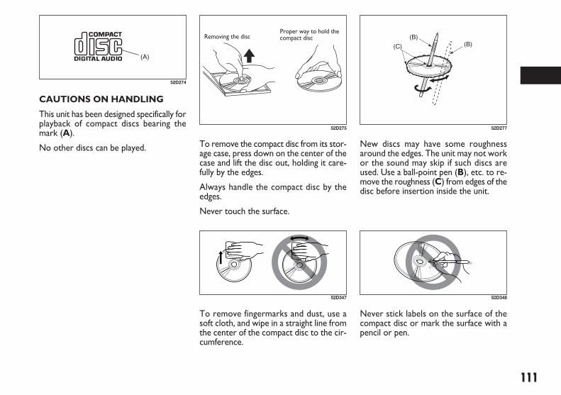
111
New discs may have some roughnessaround the edges. The unit may not workor the sound may skip if such discs areused. Use a ball-point pen (B), etc. to re-move the roughness (C) from edges of thedisc before insertion inside the unit.
To remove the compact disc from its stor-age case, press down on the center of thecase and lift the disc out, holding it care-fully by the edges.
Always handle the compact disc by theedges.
Never touch the surface.
52D275
Removing the discProper way to hold thecompact disc
52D347
To remove fingermarks and dust, use asoft cloth, and wipe in a straight line fromthe center of the compact disc to the cir-cumference.
(B)(B)(C)
52D277
52D348
Never stick labels on the surface of thecompact disc or mark the surface with apencil or pen.
CAUTIONS ON HANDLING
This unit has been designed specifically forplayback of compact discs bearing themark (A).
No other discs can be played.
(A)
52D274
071-128 SEDICI LUM FL GB 1E 19-06-2009 12:05 Pagina 111

112
Do not use any solvents such as com-mercially available cleaners, anti-staticspray, or thinner to clean compact discs.
52D349
52D350
Do not use compact discs that have largescratches, are misshaped, or cracked, etc.Use of such discs will cause damage or pre-vent the system from operating properly.
LISTENING TO A CD
❒ CDs or CD-ROMs carrying no mark(A) cannot be used.
❒ Some discs previously recorded in CD-R\CD-RW format may not be used.
NOTE
❒ Do not use commercially available CDprotection sheets or discs equippedwith stabilizers, etc. These may getcaught in the internal mechanism anddamage the disc.
❒ CD-R discs may not be able to playbackin this unit due to the recording con-ditions.
❒ CD-RW discs can not playback in thisunit.
52D351
(A)
52D274
52D291
❒ A CD is inserted with its label facing up-ward.
❒ When there is a CD already loaded inthe unit, another CD cannot be loadedat the same time. Do not use forcewhen inserting the CD into the CD in-sertion slot.
❒ If a blank disc (non recorded CD-R) isloaded in the unit, the disc will be eject-ed.
IMPORTANT
❒ Never insert your finger or hand intothe CD insertion slot. Never insert for-eign objects.
❒ Never insert a CD with glue comingout from adhesive tape or a rental CDlabel or with a trace indicating that ad-hesive tape or a rental CD label hasbeen removed. This may cause the CDnot to eject or result in a malfunction.
Do not expose compact discs to direct sun-light or any heat source.
071-128 SEDICI LUM FL GB 1E 19-06-2009 12:05 Pagina 112

113
GENERAL
1. Power on/ off knob – Volume controlknob
2. Mute button
3. Audio control button
4. Up button
5. Down button
Power On/Off
Press the power on/off knob (1) to switchpower on.
Press the power on/off knob (1) again toswitch power off.
Volume Up/Down
Turn the volume control knob (1) clock-wise to increase the volume.
Turn the volume control knob (1) counterclockwise to decrease the volume.
RADIO ANTENNA (for versions/markets, where provided)
The radio antenna at the front of the roofcan be folded down and is removable. Tofold the antenna rearward, be sure to gripthe bottom of antenna. To remove the an-tenna, turn it counterclockwise. To rein-stall the antenna, turn it clockwise firmlyby hand.
IMPORTANT To avoid damage to the ra-dio antenna:
❒ Remove the antenna when using an au-tomatic vehicle wash.
❒ Remove or fold down the antennawhen the antenna hits anything such asa low ceiling in a parking garage orputting a vehicle cover over your ve-hicle.
80G143
Mute On/Off
Press the mute button (2) to temporari-ly muffle the sound.
Press the mute button (2) again to restorethe sound to the preceding level.
NOTE
❒ In CD mode, play is temporarilystopped (pause) instead of muting.
❒ If power is switched off, or if some but-ton is pressed, mute is automatically re-leased.
Audio Control
Bass / Treble / Balance / Fader can be ad-justed.
Press the audio control button (3) to se-lect the desired item.
79J189
071-128 SEDICI LUM FL GB 1E 19-06-2009 12:05 Pagina 113

114
NOTE The Auto Volume Control (AVC)function automatically adjusts (increas-es/decreases) the sound volume in accor-dance with vehicle speed.
RADIO
4. Up button
5. Down button
6. FM/AM button
7. Preset button [1] to [6]
8. Auto search button
Radio Mode
If FM/AM button (6) is pressed when pow-er is off or in other than radio mode, thelast station you were listening to is re-ceived.
Band
Each time FM/AM button (6) is pressed inradio mode, the bands change as follows:
FM1 / FM2 / LW / MW1 / MW2 / (FM1)
Manual Tuning
The frequencies can be adjusted by press-ing the up button (4) or the down button(5).
(4): Higher frequency
(5): Lower frequency
Each time the audio control button (3) ispressed the selectable items change as fol-lows:
BAS (Bass) / TRE (Treble) / BAL (Balance) /FAD (Fader) / AVC (Auto Volume Con-trol) (only MP3 version)
Pressing the audio control button (3) againreleases Audio Control.
Press the up button (4) or the down but-ton (5) to adjust the selected item.
❒ BAS (Bass)(4): To increase bass(5): To decrease bass
❒ TRE (Treble)(4): To increase treble(5): To decrease treble
❒ BAL (Balance)(4): To decrease the left speaker’svolume(5): To decrease the right speaker’svolume
❒ FAD (Fader)(4): To decrease the rear speaker’svolume(5): To decrease the front speaker’svolume
❒ AVC (Auto Volume Control)(only MP3 version)(4): AVC OFF / AVC1 / AVC2 / AVC3(5): AVC3 / AVC2 / AVC1 / AVC OFF
Auto Tuning
If the up button (4) or the down button(5) is released after pressing it for about1 second or more, the unit searches fora station till it receives one.
(4): Higher frequency
(5): Lower frequency
NOTE If AF is ON, the unit searches forRDS stations only.
79J190
071-128 SEDICI LUM FL GB 1E 19-06-2009 12:05 Pagina 114

115
NOTE
❒ Auto Preset can be released by press-ing the auto search button (8) while au-to preset is in process.
❒ Stations can be preset for FM1, FM2,LW, MW1, and MW2 respectively.
❒ Up to six stations can be preset. If sta-tions in good receiving condition arenot found, the number of stations pre-set may be less than six.
❒ After you have preset stations, the sta-tion preset under the button with num-ber [1] is received. If none of stationsis found, the unit is reset to the pre-ceding frequency.
❒ When stations are preset, the new da-ta is written over the old data.
❒ If AF is ON, only RDS stations are pre-set.
Preset Station Calling
By pressing any of the preset buttons (7)with numbers [1] to [6], the correspond-ing station preset can be received.
NOTE If the button for a station not pre-set is pressed, the unit displays “- - -”.
Manual Preset
If any of the preset buttons (7) with num-bers [1] to [6] is pressed for about 2 sec-onds or more, the station received cor-responding to the pressed button is pre-set.
NOTE
❒ Stations can be preset for FM1, FM2,LW, MW1, and MW2 respectively.
❒ When stations are preset, the new da-ta is written over the old data.
Auto Preset
By pressing auto search button (8) forabout 2 seconds or longer, six stations ingood receiving condition on the band nowselected can be automatically preset.
RDS (Radio Data System)
1. Power on/off knob – Volume controlknob
4. Up button
5. Down button
9. Auto frequency button
10. Traffic announcement button
11. Program type button
What is RDS?
Some FM stations are broadcasting addeddata compatible with RDS. This radio set of-fers convenient functions using such data.
RDS service availability varies with areas.
Please understand the following functionsare not available in some areas.
❒ AF (Alternative Frequency)
The unit searches for a station in betterreceiving condition that emits the sameprogramme as now received, and auto-matically selects that station.
071-128 SEDICI LUM FL GB 1E 19-06-2009 12:05 Pagina 115

116
❒ REG (Region)
An area in which the AF function may beused to select stations can be set. WhenREG is ON, the AF function is effectivein the present area only.
❒ PS (Program Service Name)
Instead of the frequency, the name of thebroadcast station appears.
❒ PTY (Program Type)
Programs can be searched for by PTY.
❒ TA (Traffic Announcement)
The unit can search for stations emittingTP (traffic programmes), and tune in tosuch stations in preference to others. Sta-tions emitting TP are called TP stations.
❒ EON (Enhanced OtherNetwork)
RDS information is updated constantly inresponse to the current position.
The “EON” indicator remains lit whileRDS information is received.
❒ Emergency AnnouncementReception
Emergency announcements are automat-ically received and displayed.
AF/REG On/Off
Each time the auto frequency button (9)is pressed, AF/ REG changes as follows:
AF ON / REG OFF / AF ON/ REG ON /AF OFF / REG OFF / (AF ON/ REG OFF)
The “AF” indicator lights up when AF isON. In addition to that, the “REG” indi-cator lights up when REG is ON.
79J191
TA On/off
Press the traffic announcement button(10) to turn TA on.
Press the traffic announcement button(10) again to turn TA off.
When TA is turned on, the “TA” indica-tor lights.
The “TP” indicator remains lit while TPdata is being received.
NOTE
❒ If the up button (4) or the down but-ton (5) is pressed while TA is turnedon, the unit searches for a TP station(TP SEEK).
❒ If TP data is not received in about 20seconds after TA is turned on, TP SEEKautomatically takes place only once.
❒ If no TP station is received, the unit dis-plays “NOTHING”.
TA Standby
If TP is received when TA is ON in CD orCD changer mode, radio mode is auto-matically selected. The unit returns to thepreceding mode after TP.
071-128 SEDICI LUM FL GB 1E 19-06-2009 12:05 Pagina 116
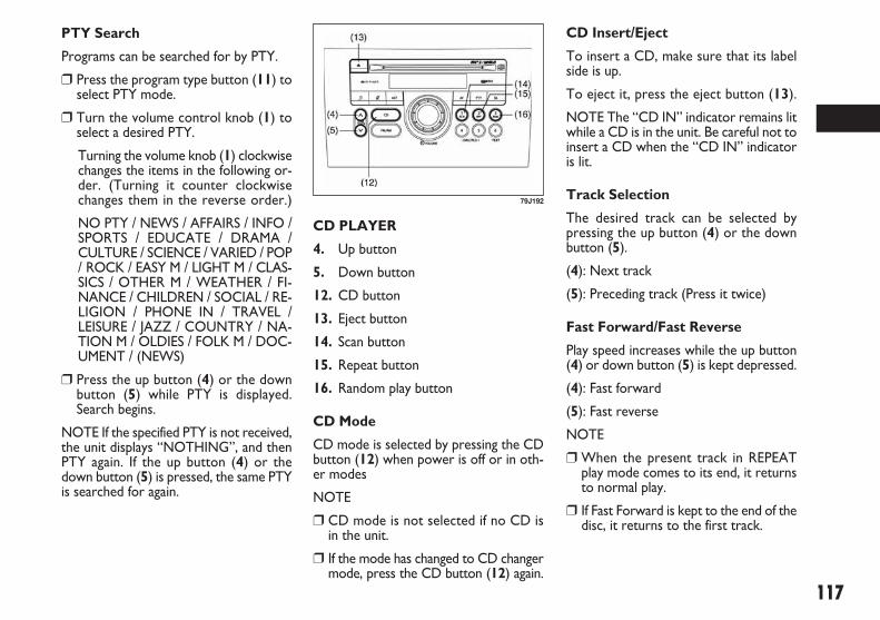
117
PTY Search
Programs can be searched for by PTY.
❒ Press the program type button (11) toselect PTY mode.
❒ Turn the volume control knob (1) toselect a desired PTY.
Turning the volume knob (1) clockwisechanges the items in the following or-der. (Turning it counter clockwisechanges them in the reverse order.)
NO PTY / NEWS / AFFAIRS / INFO /SPORTS / EDUCATE / DRAMA /CULTURE / SCIENCE / VARIED / POP/ ROCK / EASY M / LIGHT M / CLAS-SICS / OTHER M / WEATHER / FI-NANCE / CHILDREN / SOCIAL / RE-LIGION / PHONE IN / TRAVEL /LEISURE / JAZZ / COUNTRY / NA-TION M / OLDIES / FOLK M / DOC-UMENT / (NEWS)
❒ Press the up button (4) or the downbutton (5) while PTY is displayed.Search begins.
NOTE If the specified PTY is not received,the unit displays “NOTHING”, and thenPTY again. If the up button (4) or thedown button (5) is pressed, the same PTYis searched for again.
CD PLAYER
4. Up button
5. Down button
12. CD button
13. Eject button
14. Scan button
15. Repeat button
16. Random play button
CD Mode
CD mode is selected by pressing the CDbutton (12) when power is off or in oth-er modes
NOTE
❒ CD mode is not selected if no CD isin the unit.
❒ If the mode has changed to CD changermode, press the CD button (12) again.
79J192
CD Insert/Eject
To insert a CD, make sure that its labelside is up.
To eject it, press the eject button (13).
NOTE The “CD IN” indicator remains litwhile a CD is in the unit. Be careful not toinsert a CD when the “CD IN” indicatoris lit.
Track Selection
The desired track can be selected bypressing the up button (4) or the downbutton (5).
(4): Next track
(5): Preceding track (Press it twice)
Fast Forward/Fast Reverse
Play speed increases while the up button(4) or down button (5) is kept depressed.
(4): Fast forward
(5): Fast reverse
NOTE
❒ When the present track in REPEATplay mode comes to its end, it returnsto normal play.
❒ If Fast Forward is kept to the end of thedisc, it returns to the first track.
071-128 SEDICI LUM FL GB 1E 19-06-2009 12:05 Pagina 117

118
SCAN Play
For scan play (playing about 10 seconds ofthe top of each track), press the scan but-ton (14).
To release scan play, press the scan but-ton (14) again.
The “SCN” indicator remains lit duringscan play.
REPEAT Play
For repeat play (playing the present trackrepeatedly), press the repeat button (15).
To release repeat play, press the repeatbutton (15) again.
The “RPT” indicator remains lit during re-peat play.
RANDOM Play
For random play (playing the disc tracksat random), press the random play button(16).
To release random play, press the randomplay button (16) again.
The “RDM” indicator remains lit duringrandom play.
CD CHANGER
A CD changer is optional. Consult yourFiat Dealership for details.
4. Up button
5. Down button
12. CD button
14. Scan button
15. Repeat button
16. Random play button
17. Disc up button
18. Disc down button
CD Changer Mode
If the CD button (12) is pressed whenpower is off or in other modes, CD chang-er mode is selected.
NOTE
❒ CD changer mode is not selected if theCD changer is not connected, or if noCD is inserted in the unit.
❒ If the mode has changed to CD mode,press the CD button (12) again.
Disc Up/Down
The desired disc can be selected by press-ing The disc up button (17) or the discdown button (18).
(17) Next disc
(18) Preceding disc
Track Up/Down
The desired track can be selected bypressing the up button (4) or the downbutton (5).
(4): Next track
(5): Preceding track (Press it twice)
79J193
071-128 SEDICI LUM FL GB 1E 19-06-2009 12:05 Pagina 118

119
❒ DISC SCAN Play
For disc scan play (playing about 10 sec-onds of the top of the first track on eachdisc), press the scan button (14) for about1 second or more.
To release disc scan play, press the scanbutton (14) again.
The “D. SCN” indicator remains lit dur-ing disc scan play.
REPEAT Play
❒ REPEAT Play
For repeat play (playing the present trackrepeatedly), press the repeat button (15).
To release repeat play, press the repeatbutton (15) again.
The “RPT” indicator remains lit during re-peat play.
❒ DISC REPEAT Play
For disc repeat play (playing the presentdisc repeatedly), press the repeat button(15) for about 1 second or more.
To release disc repeat play, press the re-peat button (15) again.
The “D.RPT” indicator remains lit duringdisc repeat play.
RANDOM Play
❒ RANDOM Play
For random play (playing the disc tracksat random), press the random play button(16).
To release random play, press the randomplay button (16) again.
The “RDM” indicator remains lit duringrandom play.
❒ DISC RANDOM Play
For disc random play (playing the tracksof all discs at random), press the randomplay button (16) for about 1 second ormore.
To release disc random play, press therandom play button (16) again.
The “D.RDM” indicator remains lit duringdisc random play.
Fast Forward/Fast Reverse
Play speed increases while the up button(4) or down button (5) is kept depressed.
(4): Fast forward
(5): Fast reverse
NOTE
❒ When the present track in REPEATplay mode comes to its end, it returnsto normal play.
❒ If Fast Forward is kept to the end of thedisc, it returns to the first track.
SCAN Play
❒ SCAN Play
For scan play (playing about 10 seconds ofthe top of each track on the present disc),press the scan button (14).
To release scan play, press the scan but-ton (14) again.
The “SCN” indicator remains lit duringscan play.
071-128 SEDICI LUM FL GB 1E 19-06-2009 12:05 Pagina 119

120
MP3/WMA PLAYER (for versions/markets, where provided)
4. File up button
5. File down button
12. CD button
13. Eject button
15. Repeat button
16. Random play button
17. Folder up button
18. Folder down button
20. Text display button
What is MP3/WMA?
MP3 (MPEG1/2 Audio Layer-II/III) andWMA (Windows MediaTM Audio) arethe compression formats of digital audio.The former is developed by MPEG (Mo-tion Picture Experts Group), and the lat-ter is developed by Microsoft Corpora-tion. Using these compression formats,you can record the contents of about 10music CDs on a single CD media (This fig-ures refer to data recorded on a 650 MBCD-R or CD-RW at a fixed bit rate of 128kbps and a sampling frequency of 44.1kHz).
Points to remember when makingMP3/WMA files
Common
❒ High bit rate and high sampling fre-quency are recommended for highquality sounds.
❒ Selecting VBR (Variable Bit Rate) is notrecommended because playing time isnot displayed properly and sound maybe skipped.
❒ The playback sound quality differs de-pending on the encoding circumstances.For details, refer to the user manual ofyour own encoding software and writ-ing software.
MP3
❒ It is recommended to set the bit rateto “128 kbps or more” and “fixed”.
WMA
❒ It is recommended to set the bit rateto “64 kbps or more” and “fixed”.
❒ Do not set the copy protect attributeon the WMA file to enable this unit toplay back.
NOTE Never assign the “.mp3”, or“.wma” file name extension to a file thatis not in the MP3/WMA format. This maynot only produce noise from the speakerdamage, but also damage your hearing.
Recording MP3/WMA files on a CD-media
❒ You are recommended to minimize thechances of making a disc that containsboth CD-DA files and MP3/WMA files.
❒ If CD-DA files are on the same disc asMP3 or WMA files, the songs may notplay in the intended order, or somesongs may not play at all.
❒ When storing MP3 data and WMA da-ta on the same disc, use different fold-ers for each data.
❒ Do not record files other thanMP3/WMA files and unnecessary fold-er on a disc.
❒ The name of an MP3/WMA file shouldbe added by rules as shown in the fol-lowing descriptions and also complywith the rules of each file system.
79J194
071-128 SEDICI LUM FL GB 1E 19-06-2009 12:05 Pagina 120

121
❒ The file extension “.mp3” or “.wma”should be assigned to each file de-pending on the file format.
❒ You may encounter trouble in playingMP3/WMA files or displaying the in-formation of MP3/WMA files recordedwith certain writing software or CDrecorders.
❒ This unit does not have a play list func-tion.
❒ Although Multi-session recording issupported, the use of Disc-at-Once isrecommended.
Compression formats MP3
❒ Bit rateMPEG1 Audio Layer II : 64k – 320 kbpsMPEG1 Audio Layer III : 32k – 320 kbpsMPEG2 Audio Layer II : 64k – 320 kbpsMPEG2 Audio Layer III : 8k – 160 kbps
❒ Sampling frequencyMPEG1 Audio Layer II/III : 44.1 k/48 k/32kHzMPEG2 Audio Layer II/III : 22.05 k/24 k/16 kHz
WMA (Ver.7, Ver.8, Ver. 9*)❒ Bit rate 32 k – 192 kbps❒ Sampling frequency 44.1 k/48 k/32 kHz
* WMA 9 Professional/LossLess/Voice are notsupported.
Supported file systems
ISO 9660 Level 1/Level 2, Apple Extensionto ISO 9660, Joliet, Romeo
Maximum number of files/folders
❒ Maximum number of files: 511 (files +folders)
❒ Maximum number of files in one fold-er: 255
❒ Maximum depth of trees: 8
❒ Maximum number of folders: 255 (Rootfolder is included.)
MP3/WMA Mode
MP3/WMA mode is selected by pressingthe CD button (12) when power is off orin other modes.
NOTE
❒ MP3/WMA mode is not selected if noMP3/WMA disc is in the unit.
❒ If the mode has changed to CD chang-er mode, press the CD button (12)again.
Disc Insert/Eject
To insert a disc, make sure that its label-side is up. To eject it, press the eject but-ton (13).
NOTE The “CD IN” indicator remains litwhile a disc is in the unit. Be careful not toinsert a disc when the “CD IN” indicatoris lit.
File Up/Down
The desired file can be selected by press-ing the file up button (4) or the file downbutton (5).
(4): Next file
(5): Preceding file (Press it twice.)
Folder Up/Down
The desired folder can be selected bypressing the folder up button (17) or thefolder down button (18).
(17): Next folder
(18): Preceding folder
Fast Forward/Fast Reverse
Play speed increases while the button (4)or (5) is kept depressed.
(4): Fast forward
(5): Fast reverse
NOTE
❒ When the present file in REPEAT playmode comes to its end, it returns tonormal play.
❒ If Fast Forward is kept to the end of thedisc, it returns to the first file.
071-128 SEDICI LUM FL GB 1E 19-06-2009 12:05 Pagina 121
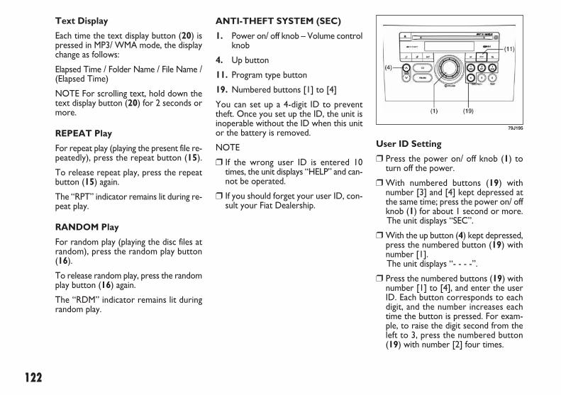
122
User ID Setting
❒ Press the power on/ off knob (1) toturn off the power.
❒ With numbered buttons (19) withnumber [3] and [4] kept depressed atthe same time; press the power on/ offknob (1) for about 1 second or more.The unit displays “SEC”.
❒ With the up button (4) kept depressed,press the numbered button (19) withnumber [1].The unit displays “- - - -”.
❒ Press the numbered buttons (19) withnumber [1] to [4], and enter the userID. Each button corresponds to eachdigit, and the number increases eachtime the button is pressed. For exam-ple, to raise the digit second from theleft to 3, press the numbered button(19) with number [2] four times.
ANTI-THEFT SYSTEM (SEC)
1. Power on/ off knob – Volume controlknob
4. Up button
11. Program type button
19. Numbered buttons [1] to [4]
You can set up a 4-digit ID to preventtheft. Once you set up the ID, the unit isinoperable without the ID when this unitor the battery is removed.
NOTE
❒ If the wrong user ID is entered 10times, the unit displays “HELP” and can-not be operated.
❒ If you should forget your user ID, con-sult your Fiat Dealership.
79J195
Text Display
Each time the text display button (20) ispressed in MP3/ WMA mode, the displaychange as follows:
Elapsed Time / Folder Name / File Name /(Elapsed Time)
NOTE For scrolling text, hold down thetext display button (20) for 2 seconds ormore.
REPEAT Play
For repeat play (playing the present file re-peatedly), press the repeat button (15).
To release repeat play, press the repeatbutton (15) again.
The “RPT” indicator remains lit during re-peat play.
RANDOM Play
For random play (playing the disc files atrandom), press the random play button(16).
To release random play, press the randomplay button (16) again.
The “RDM” indicator remains lit duringrandom play.
071-128 SEDICI LUM FL GB 1E 19-06-2009 12:05 Pagina 122

123
User ID Entry
Once the ID is set up, this unit displays“SEC” to prompt you to enter your userID when the power is turned on again inthe case of removal of this unit or the bat-tery.
The unit cannot be used unless the ID isentered in the following order.
NOTE The unit does not display “SEC”when the power is turned on within 20seconds from the last use.
❒ With the up button (4) kept depressed,press the numbered button (19) withnumber [1].The unit displays “- - - -”.
❒ Press the numbered buttons (19) withnumber [1] to [4], and enter the userID. Each button corresponds to eachdigit. Enter the stored user ID.
❒ Press program type button (11) forabout 2 second or more to enter.Power is switched off.When you switch the unit back on, it isin radio mode for normal use.
Erasing User ID
Your stored user ID can be erased. Aftererasing it, you may set a new user ID.Therefore, you can change your user IDas often as you like.
❒ Press the power on/off knob (1) to turnoff the power.
❒ With the numbered buttons (19) withnumbers [3] and [4] kept depressed atthe same time, press the power on/ offknow (1) for about 1 second or more.The unit displays “SEC”.
❒ With the up button (4) kept depressed,press the numbered button (19) withnumber [1].The unit displays “- - - -”.
❒ Press the numbered buttons (19) withnumber [1] to [4], and enter the user ID.Each button corresponds to each digit.Enter the stored user ID.
❒ Press the program type button (11) forabout 2 seconds or more to enter.The power is turned off approx, 10 sec-onds after “- - - -” is displayed.
❒ Press the program type button (11) forabout 2 second or more to enter.Power is switched off after the unit dis-plays “SEC”.Once the ID is set up, the ID is re-quired at power-on when this unit orthe battery has been removed.
071-128 SEDICI LUM FL GB 1E 19-06-2009 12:05 Pagina 123

124
TROUBLESHOOTING
If you suspect something is wrong, then please check and take steps as described below.
If the described suggestions do not solve the problem, it is recommended to take the unit to your nearest dealer.
Common
Problem Possible cause Possible solution
A lot of noise
Unable to operate
A mobile phone is used nearby.
The security function is on.
If you are going to use a mobile phone, use itaway from the unit.
If the unit displays “SEC”, enter your user ID.If the unit displays “HELP”, consult your dealer.
Radio
Problem Possible cause Possible solution
A lot of noise
Unable to receive by auto tuning
Unable to preset stations of signals powerful enough by auto preset
Tune it exactly to the station.
Pick up a station by manual tuning.Turn AF off.
Turn AF off.
The unit is not exactly tuned in to the station.
There is no station emitting signalspowerful enough.If AF is ON, the unit searches for RDSstations only.
If AF is ON, only RDS stations will bepreset.
071-128 SEDICI LUM FL GB 1E 19-06-2009 12:05 Pagina 124

125
ERROR DISPLAY MESSAGES
CD
Display Possible cause Possible solution
ERROR 1
ERROR 3
Insert the disc with its label side up.Check the disc that it is not warped and is freeof flaws.If ERROR 1 does not go out when a normal discis inserted, consult your Fiat Dealership.
If CD is inserted in the unit, press the eject button (13) to remove the disc.If the disc cannot be ejected, consult your FiatDealership.
The disc cannot be read.
The player developed an error of anunidentified cause.
CD
Problem Possible cause Possible solution
Sound skipping or noise
CD cannot be inserted
Wipe the disc with a soft cloth.Replace the disc with another without flaws.
Insert a CD after having removed the already inserted disc by pressing the eject button (13).
The disc is dirty.The disc has a major flaw or is warped.
A disc is already loaded.
071-128 SEDICI LUM FL GB 1E 19-06-2009 12:05 Pagina 125

126
To change the radio station:
❒ To advance to the next preset station,push the switch (5) briefly (only MP3version).
❒ To select the previous preset station,push the switch (6) briefly (only MP3version).
❒ To scan the higher frequency radiostation, push and hold the switch (5).
❒ To scan the lower frequency radio sta-tion, push and hold the switch (6).
To scan the selection on a CD:
❒ To advance to the next track on a CD,push the switch (5).
❒ To select the previous track on a CD,push the switch (6).
For vehicle with navigation system
Refer to the chart below how to use theswitches on the steering wheel.
REMOTE AUDIO CONTROLS(for versions/markets, where provided)
You can control basic functions of the au-dio system with the switches on the steer-ing wheel. How to use the switches is dif-ferent if the navigation system is equippedor not.
For vehicle without navigationsystem
To control the volume:
❒ To increase the volume, push theswitch (1).
❒ To decrease the volume, push theswitch (2).
❒ To mute, push the switch (3).
To select the mode, push the switch (4).
You can also turn on the audio system bypushing the switch (4).
(3)
(1)
(2)
(4)
(5)
(6)
63J305
071-128 SEDICI LUM FL GB 1E 19-06-2009 12:05 Pagina 126

127
Switch ModeSwitch operation Tuner CD CD (MP3, WMA)
(1)
(2)
(3)
(4)
(5)
(6)
Push briefly
Push long
Push briefly
Push long
Push briefly
Push long
Push briefly
Push briefly
Push long
Push briefly
Push long
increase the volume
increase the volume rapidly
decrease the volume
decrease the volume rapidly
scan to a higher frequency preset
radio station
scan to a lower frequency preset
radio station
scan to a lower frequency radio
station
scan to a lower frequency radio
station
incoming call: answer call(if installed with optional hands free device)
during a call: end call(if installed with optional hands free device)
redialing
start the voice control (if installed with optional microphone)
increase the volume
increase the volume rapidly
decrease the volume
decrease the volume rapidly
advance to next track
fast forward a track
return to previous track
fast rewind a track
increase the volume
increase the volume rapidly
decrease the volume
decrease the volume rapidly
advance to next track
advance to next folder
return to previous track
return to previous folder
Full map navigation system
(3)
(1)
(2)
(4)
(5)
(6)
79J233
071-128 SEDICI LUM FL GB 1E 19-06-2009 12:05 Pagina 127

128
Switch ModeSwitch operation Music Catcher SD card (MP3, WMA)
(1)
(2)
(3)
(4)
(5)
(6)
Push briefly
Push long
Push briefly
Push long
Push briefly
Push long
Push briefly
Push briefly
Push long
Push briefly
Push long
increase the volume
increase the volume rapidly
decrease the volume
decrease the volume rapidly
advance to next track
advance to next folder
return to previous track
return to previous folder
incoming call: answer call(if installed with optional hands free device)
during a call: end call(if installed with optional hands free device)
redialing
start the voice control (if installed with optional microphone)
increase the volume
increase the volume rapidly
decrease the volume
decrease the volume rapidly
advance to next track
advance to next folder
return to previous track
return to previous folder Full map navigation system
(3)
(1)
(2)
(4)
(5)
(6)
79J233
071-128 SEDICI LUM FL GB 1E 19-06-2009 12:05 Pagina 128

129
OOTTHHEERR CCOONNTTRROOLLSS AANNDD EEQQUUIIPPMMEENNTT
60G407
PARKING BRAKE LEVER.................................................... 130PEDAL...................................................................................... 131GEARSHIFT LEVER............................................................... 132FUEL FILLER CAP ................................................................. 132FOLDING REAR SEATS ...................................................... 134SUN VISOR ............................................................................ 137INTERIOR LIGHT SWITCH............................................... 138SPOT LIGHT (for versions/markets, where provided). 138FRONT SEAT HEATER (for versions/markets, where provided)........................... 139ASSIST GRIPS (for versions/markets, where provided) 140ENGINE HOOD ................................................................... 140CUP HOLDER (for versions/markets, where provided)........................... 142FRAME HOOKS .................................................................... 143TIRE CHANGING TOOL................................................... 144FRONT SEAT BACK POCKET (for versions/markets, where provided)........................... 145SHOPPING HOOK (for versions/markets, where provided)........................... 145LUGGAGE RESTRAINT LOOPS (for versions/markets, where provided)........................... 145LUGGAGE COMPARTMENT COVER (for versions/markets, where provided)........................... 146LUGGAGE COMPARTMENT LIGHT.............................. 146RADIO ANTENNA (for versions/markets, where provided)........................... 147INSTALLATION OF RADIO FREQUENCY TRANSMITTERS.................................................................... 147ROOF RAILS OR ROOF RACK ANCHORS (for versions/markets, where provided)........................... 147
4
129-148 SEDICI LUM FL GB 1E 19-06-2009 13:31 Pagina 129

130
PARKING BRAKELEVER
The parking brake lever is located be-tween the seats. To set the parking brake,hold the brake pedal down and pull theparking brake lever all the way up. To re-lease the parking brake, hold the brakepedal down, pull up slightly on the parkingbrake lever, push the button on the endof the lever with your thumb, and lowerthe lever to its original position.
1. To set
2. To release
3. To release
(2)
(3)
(1)
54G039
Never drive your vehicle withthe parking brake on: rear
brake effectiveness can be reducedfrom overheating, brake life may beshortened, or permanent brake dam-age may result.If the parking brake does not holdthe vehicle securely or does not ful-ly release, have your vehicle in-spected immediately by an autho-rized Fiat Dealership.
WARNING
Always set the parking brakefully before leaving your ve-
hicle or it may move, causing injuryor damage. When parking, make surethe gearshift lever for manualtransaxle vehicles is in 1st gear or “R”(Reverse) and the gearshift lever forautomatic transaxle vehicles is in “P”(Park). Remember, even though thetransaxle is in gear or in Park, youmust set the parking brake fully.
WARNING
When parking the vehicle inextremely cold weather, the
following procedure should be used:1) Set the parking brake.2) Manual transaxle - turn off the en-
gine, then shift into reverse or firstgear.Automatic transaxle - shift into“P” (Park) and turn off the engine.
3) With the engine off, get out of thevehicle and put chocks under thewheels.
4) Release the parking brake.When you return to your vehicle,you must remember to first set theparking brake, then remove thewheel chocks.
WARNING
For automatic transaxle vehicles, alwaysset the parking brake before moving thegearshift lever to the “P” (PARK) position.If you park on an incline and shift into “P”before setting the parking brake, theweight of the vehicle may make it difficultto shift out of “P” when you are ready todrive the vehicle.
When preparing to drive the vehicle,move the gearshift lever out of the “P” po-sition before releasing the parking brake.
129-148 SEDICI LUM FL GB 1E 19-06-2009 13:31 Pagina 130
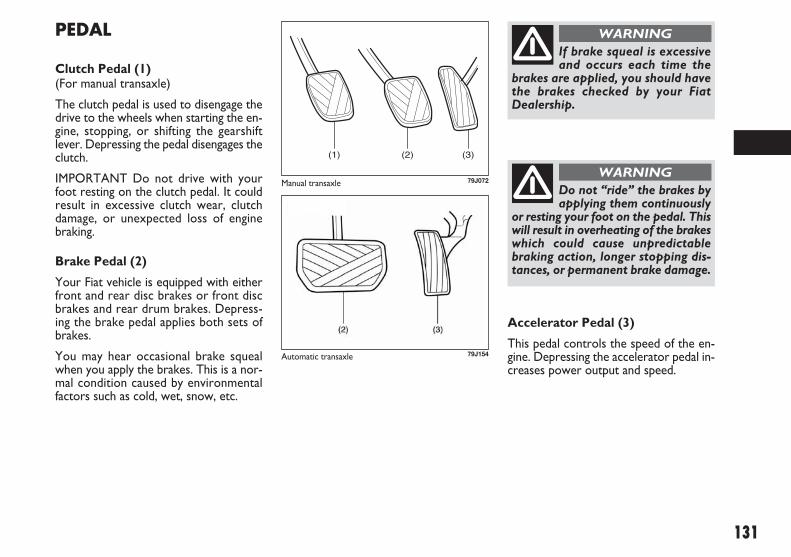
131
PEDAL
Clutch Pedal (1)(For manual transaxle)
The clutch pedal is used to disengage thedrive to the wheels when starting the en-gine, stopping, or shifting the gearshiftlever. Depressing the pedal disengages theclutch.
IMPORTANT Do not drive with yourfoot resting on the clutch pedal. It couldresult in excessive clutch wear, clutchdamage, or unexpected loss of enginebraking.
Brake Pedal (2)
Your Fiat vehicle is equipped with eitherfront and rear disc brakes or front discbrakes and rear drum brakes. Depress-ing the brake pedal applies both sets ofbrakes.
You may hear occasional brake squealwhen you apply the brakes. This is a nor-mal condition caused by environmentalfactors such as cold, wet, snow, etc.
Accelerator Pedal (3)
This pedal controls the speed of the en-gine. Depressing the accelerator pedal in-creases power output and speed.
(1) (2) (3)
79J072
If brake squeal is excessiveand occurs each time the
brakes are applied, you should havethe brakes checked by your FiatDealership.
WARNING
Do not “ride” the brakes byapplying them continuously
or resting your foot on the pedal. Thiswill result in overheating of the brakeswhich could cause unpredictablebraking action, longer stopping dis-tances, or permanent brake damage.
WARNINGManual transaxle
79J154Automatic transaxle
129-148 SEDICI LUM FL GB 1E 19-06-2009 13:31 Pagina 131

132
FUEL FILLER CAP
The fuel filler cap is located on the left rearside of the vehicle. The fuel filler lid can beunlocked by pulling up the opener lever lo-cated on the outboard side of the driver’sseat and locked by simply closing the lid.
GEARSHIFT LEVER
Your vehicle is equipped with either amanual transaxle or automatic transaxle.
The gearshift lever for each transaxle typeis shown in the illustrations. For details onhow to use the transaxle, refer to “Usingthe Transaxle” in the “OPERATINGYOUR VEHICLE” section.
63J051
80J2033
Remove the fuel filler capslowly. The fuel may be un-
der pressure and may spray out, caus-ing injury.
WARNING
Gasoline is extremely flam-mable. Do not smoke when
refueling, and make sure there are noopen flames or sparks in the area.
WARNING
Manual transaxle: to changegears properly you must
push the clutch pedal fully down. It istherefore essential that there is noth-ing under the pedals: make sure themats are lying flat and do not get inthe way of the pedals.
WARNING
IMPORTANT Do not drive with yourhand resting on the gear lever as the forceexerted, even if slight, could lead over timeto premature wear on the gearbox inter-nal components.
5-speed manual transaxle (for Gasoline engine)
77J021Automatic transaxle
6-speed manual transaxle (for Diesel engine)
129-148 SEDICI LUM FL GB 1E 19-06-2009 13:31 Pagina 132

133
To remove the fuel filler cap:
� Open the fuel filler door.
� Remove the cap by turning it counter-clockwise.
NOTE The cap holder (1) can hold the fu-el filler cap (2) when refueling.
To reinstall the fuel filler cap:
� Turn the cap clockwise until you hearseveral clicks.
� Close the fuel filler door.
79J048
(1)
(2)
56KN078
79J049
79K053
Open Close
If you need to replace the fu-el cap, use a genuine Fiat cap
or its equivalent. Use of an impropercap can result in a malfunction of thefuel system or emission control system.It may also result in fuel leakage in theevent of an accident.
WARNING
129-148 SEDICI LUM FL GB 1E 19-06-2009 13:31 Pagina 133
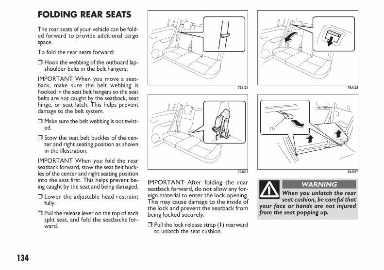
134
IMPORTANT After folding the rearseatback forward, do not allow any for-eign material to enter the lock opening.This may cause damage to the inside ofthe lock and prevent the seatback frombeing locked securely.
� Pull the lock release strap (1) rearwardto unlatch the seat cushion.
FOLDING REAR SEATS
The rear seats of your vehicle can be fold-ed forward to provide additional cargospace.
To fold the rear seats forward:
� Hook the webbing of the outboard lap-shoulder belts in the belt hangers.
IMPORTANT When you move a seat-back, make sure the belt webbing ishooked in the seat belt hangers so the seatbelts are not caught by the seatback, seathinge, or seat latch. This helps preventdamage to the belt system.
� Make sure the belt webbing is not twist-ed.
� Stow the seat belt buckles of the cen-ter and right seating position as shownin the illustration.
IMPORTANT When you fold the rearseatback forward, stow the seat belt buck-les of the center and right seating positioninto the seat first. This helps prevent be-ing caught by the seat and being damaged.
� Lower the adjustable head restraintfully.
� Pull the release lever on the top of eachsplit seat, and fold the seatbacks for-ward.
79J121
79J213
(1)
63J057
79J123
When you unlatch the rearseat cushion, be careful that
your face or hands are not injuredfrom the seat popping up.
WARNING
129-148 SEDICI LUM FL GB 1E 19-06-2009 13:31 Pagina 134

135
� Unhook the strap (2) by pushing downthe hook as shown in the illustration.
� Hook the strap (2) to the front seathead restraint as shown in the illustra-tion.
IMPORTANT When securing the foldedrear seat with a strap, adjust the straplength so that the rear seat will not move.
� Fold the entire seat forward.
79J124
(2)
79J125
(2)
63J059
Luggage or other cargoshould be stowed in the lug-
gage compartment with the rear seatin an upright position, whenever pos-sible. If you need to carry cargo in thepassenger compartment with the rearseat back folded forward, be sure tosecure the cargo or it may be thrownabout, causing injury. Never pile car-go higher than the seatbacks.
WARNING
129-148 SEDICI LUM FL GB 1E 19-06-2009 13:31 Pagina 135
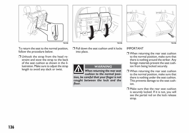
136
� Pull down the seat cushion until it locksinto place.
IMPORTANT
� When returning the rear seat cushionto the normal position, make sure thatthere is nothing around the striker. Anyforeign materials prevent the seat cush-ion from being locked securely.
� When returning the rear seat cushionto the normal position, make sure thatthere is nothing under the seat cushion.This prevents damage to the seat cush-ion.
� Make sure that the rear seat cushionis securely locked. If it is not, you willsee the partial red on the lock releasestrap.
To return the seat to the normal position,follow the procedure below.
� Unhook the strap from the head re-straint and stow the strap to the backof the seat cushion as shown in the il-lustration. Make sure to adjust the straplength to avoid any slack or twist.
79J126 79J129 79J168
When returning the rear seatcushion to the normal posi-
tion, be careful that your finger is notcaught between the lock and thefloor.
WARNING
129-148 SEDICI LUM FL GB 1E 19-06-2009 13:31 Pagina 136

137
SUN VISOR
The sun visors can be pulled down toblock glare coming through the wind-shield, or they can be unhooked andturned to the side to block glare comingthrough the side window.
IMPORTANT After securing the rearseatback, make sure that it is locked se-curely. If it is not, you will see red in therelease lever.
Do not put your hand intothe rear seatback lock open-
ing, or your finger may get caught andbe injured.
WARNING 79J161
79J12763J130
LOCK UNLOCK
Red
IMPORTANT When unhooking andhooking a sun visor, be sure to handle itby the hard plastic parts or the sun visorcan be damaged.
� Raise the seatback until it locks intoplace.
After returning the seat, try moving theseat and seatback to make sure they aresecurely latched.
129-148 SEDICI LUM FL GB 1E 19-06-2009 13:31 Pagina 137

138
NOTE The number of doors involved inthe lighting operation of the interior lightdepends on the vehicle specification. Ifthere is a switch (rubber projection) at thedoor opening as shown, the door is in-volved in the lighting operation.
SPOT LIGHT (for versions/markets, where provided)
Push the switch to turn on the light andpush it again to turn off the light.
INTERIOR LIGHTSWITCH
This light switch has three positions whichfunction as described below:
ON (1)The light comes on and stays on regard-less of whether the door is open orclosed.
DOOR (2)The light comes on when the door isopened.After closing all doors, the light will remainon for about 15 seconds and then fadeout. If you insert the key into the ignitionswitch during that time, the light will startto fade out immediately.After removing the key from the ignitionswitch, the light will turn on for about 15seconds and then fade out.
OFF (3)The light remains off even when the dooris opened.
(1)(2)(3)
64J104
79J075
79J074
129-148 SEDICI LUM FL GB 1E 19-06-2009 13:31 Pagina 138

139
FRONT SEAT HEATER (for versions/markets, where provided)
With the ignition switch in the “ON” po-sition, push in one or both of the seatheater switches to warm the correspond-ing seat(s). The indicator light below theswitch will also come on. To turn off theseat heater, push in the switch again. Theindicator light below the switch will go off.
IMPORTANT To avoid damaging theheater element:
� Do not subject the front seats to heavyimpacts, such as children jumping onthem.
� Do not cover the seat with any insu-lating materials such as blankets orcushions.
79J076
Improperly using the seatheater can be hazardous. An
occupant can suffer burns even if theheating temperature is fairly low, if theoccupant is wearing thin pants, a thinskirt or shorts and leaves the heater onfor long periods.Avoid using the seat heater for theseoccupants:– People who have reduced feeling intheir legs, including the elderly orthose with certain disabilities.– Small children, or anyone with sen-sitive skin.– People who are asleep or under theinfluence of alcohol or other drugswhich make them tired.
WARNING
86G064
129-148 SEDICI LUM FL GB 1E 19-06-2009 13:31 Pagina 139

❒ Push the under-hood release leversideways with your finger, as shownin the illustration. While pushing thelever, lift up the engine hood.
ENGINE HOOD
To open the engine hood:
❒ Pull the hood release handle located onthe outboard side of the driver’s sideof the instrument panel. This will dis-engage the engine hood lock halfway.
140
ASSIST GRIPS (for versions/markets, where provided)
Assist grips are provided for convenience.
IMPORTANT To avoid damaging the as-sist grip and the molded headlining, do nothang down the assist grip.
54G249 79J077
80J045
129-148 SEDICI LUM FL GB 1E 23-06-2009 9:11 Pagina 140

141
� Continue to lift up the hood until it ishigh enough to support with the proprod.
79JM022
If the supporting rod is notpositioned correctly the bon-
net may fall violently.
WARNING
To close the engine hood:
� Lift the hood up slightly and remove theprop rod from the hole. Put the proprod back to the holding clip.
� Lower the hood close to the bumper,then let it drop down. Make sure thehood is securely latched after closing.
For safety reasons the bon-net must be closed properly
to avoid its opening while the vehi-cle is travelling. Therefore, alwayscheck it is properly closed and thecatch engaged. Should you noticethat the catch is not perfectly en-gaged when travelling, stop the vehi-cle immediately and close the bonnet.
WARNING
129-148 SEDICI LUM FL GB 1E 19-06-2009 13:31 Pagina 141

142
CUP HOLDER (for versions/markets, where provided)
The cup holders are provided in the cen-ter console.
79J051
79J052
80JM087
80JM055
80JM143
Do not use the cup holder tohold cups containing hot liq-
uids, or sharpedged, hard or break-able objects. Objects in the cup hold-er may be thrown about during a sud-den stop or impact, and could causepersonal injury.
WARNING
Pull the lid to open.
Bottle holder
You should hold a bottle with a cap in theholder
Front
Rear
129-148 SEDICI LUM FL GB 1E 19-06-2009 13:31 Pagina 142

143
IMPORTANT Never use the hooks (1)and (2) for trailer/train shipping purpos-es to prevent damage to the vehicle.
FRAME HOOKS
Frame hooks are provided on the front(1), rear (2) and side (3) (for ver-sions/markets, where provided) of the ve-hicle. The hooks (1) and (2) are used foremergency situations. The hooks (3) (forversions/markets, where provided) areused for trailer/train shipping purposes.
To tow your vehicle on the road or high-way, follow the instruction of “Towing” in“EMERGENCY SERVICE” or “VEHICLELOADING AND TOWING” section.
(1)
79JF019
(2)
79J080
Front
Rear
Side (if equipped)
Do not use the frame hooksto tow another vehicle or to
have your vehicle towed on the roador highway.
The hooks (1) and (2) are designed foruse in emergency situations only, suchas if your vehicle or another vehiclegets stuck in deep mud or snow.
The hooks (3) (for versions/markets,where provided) are provided fortrailer/ train shipping purposes.
WARNING
(3)
79J081
(3)
79J132
129-148 SEDICI LUM FL GB 1E 19-06-2009 13:31 Pagina 143

144
TIRE CHANGING TOOL
The jack, wheel brace, jack handle arestowed in the luggage compartment.
To remove the spare tire, turn its bolt (1)counterclockwise and remove it.
To remove the jack, turn its shaft coun-terclockwise and pull the jack out of thestorage bracket.
To stow the jack, place it in the storagebracket and turn the shaft clockwise un-til the jack is securely held in place.
79JM014
79J083
(1)
80J048
79J085
The jack shall only be usedfor changing wheels on the
vehicle with which it is provided or oncars of the same model. It must not beused for other purposes such as for in-stance raising vehicles of other mod-els. In no case should it be used for re-pairs under the vehicle. Incorrect po-sitioning of the jack may cause thejacked vehicle to fall. Do not use thejack for higher capacities than statedon its label.
It is important to read the jacking in-structions in the “EMERGENCY SER-VICE” section of this manual beforeattempting to use the jack.
WARNING
After using the tire changingtools, be sure to stow them
securely or they can cause injury if anaccident occurs.
WARNING
79J086
129-148 SEDICI LUM FL GB 1E 19-06-2009 13:31 Pagina 144

145
LUGGAGE RESTRAINTLOOPS(for versions/markets, where provided)
Four luggage restraint loops are provid-ed on the luggage compartment floor. Anoptional rubber net can be hooked tothese loops to help keep cargo from mov-ing around in the luggage compartmentduring normal driving.
FRONT SEAT BACKPOCKET(for versions/markets, where provided)
This pocket is provided for holding lightand soft things such as gloves, newspapersor magazines.
60B119
Do not put hard or break-able objects in the pocket. If
an accident occurs, objects such asbottles, cans, etc. can injure the oc-cupants in the rear seat.
WARNING80JM058 79J087
SHOPPING HOOK (for versions/markets, where provided)
LUGGAGE COMPARTMENT
You can hang the shopping bag or othersuitable objects on the hook.
This hook is not designed for large orheavy items.
129-148 SEDICI LUM FL GB 1E 19-06-2009 13:31 Pagina 145

146
LUGGAGECOMPARTMENT LIGHT
When you open the rear door with theluggage compartment light switch in the“ON” position (1), the light comes on andremains on as long as you keep the reardoor open.
When the luggage compartment lightswitch is in the “OFF” position (2), thelight remains off regardless of whether therear door is opened or closed.
IMPORTANT Do not leave the rear dooropen with the luggage compartment lightswitch in the “ON” position for a longtime, or the battery will discharge.
LUGGAGECOMPARTMENT COVER(for versions/markets, where provided)
Luggage or other cargo placed in the lug-gage compartment are hidden from viewby a luggage compartment cover.
79J128
79J162
(1) (2)
79J053
Do not carry items on top ofthe luggage compartment
cover, even if they are small and light.Objects on top of the cover could bethrown about in an accident, causinginjury, or could obstruct the driver’srear view.
WARNING
129-148 SEDICI LUM FL GB 1E 19-06-2009 13:31 Pagina 146

147
INSTALLATION OFRADIO FREQUENCYTRANSMITTERS
We recommend that you always ask a FI-AT Dealership about frequency band, maxoutput power, antenna position at vehicleand specific conditions for installationand/or use before installing a radio trans-mitter in your vehicle. Such equipmentsmay cause the electronic control systemto malfunction if they are incorrectly in-stalled or they are not suited for the ve-hicle.
RADIO ANTENNA (for versions/markets, where provided)
The radio antenna at the front of the roofcan be folded down and is removable. Tofold the antenna rearward, be sure to gripthe bottom of antenna. To remove the an-tenna, turn it counterclockwise. To rein-stall the antenna, turn it clockwise firmlyby hand.
IMPORTANT To avoid damage to the ra-dio antenna:
� Remove the antenna when using an au-tomatic vehicle wash.
� Remove or fold down the antennawhen the antenna hits anything such asa low ceiling in a parking garage orputting a vehicle cover over your ve-hicle.
80G143
ROOF RAILS OR ROOFRACK ANCHORS (for versions/markets, where provided)
You can use the roof rails to attach theoptional roof rack which is available atyour Fiat Dealership. If you use a roofrack, observe the instructions and pre-cautions in this section and provided withthe roof rack.
� Make sure the roof rack is securely in-stalled.
� To mount various types of cargo (suchas skis, bicycles, etc.) properly, use suit-able attachments which are availablefrom your Fiat Dealership. Be sure toinstall the attachments properly and se-curely according to the instructionsprovided. Do not mount cargo direct-ly on the roof panel. The cargo candamage the roof panel.
� The gross weight of the roof rack pluscargo must not exceed the loading ca-pacity (50 kg -110 lbs). Also, do not letthe gross vehicle weight (fully loadedvehicle including driver, passengers, car-go, roof load and trailer tongue weight)exceed the Gross Vehicle Weight Rat-ing (GVWR) listed in the “SPECIFICA-TIONS” section of this manual.
129-148 SEDICI LUM FL GB 1E 19-06-2009 13:31 Pagina 147

148
� Mount and secure the cargo onto theroof rack properly according to the in-structions provided. Be sure to stowthe heaviest items at the bottom anddistribute the cargo as evenly as possi-ble.
� Do not carry items so large that theyhang over the bumpers or the sides ofthe vehicle, or block your view.
� Secure the front and rear ends of longitems – such as wood panels, surf-boards and so forth – to both the frontand rear of the vehicle. You should pro-tect the painted surfaces of the vehi-cle from scuffing caused by tie-downropes.
� Check periodically to make sure theroof rack is securely installed and freefrom damage.
� For vehicles with roof rack anchors,make sure the anchors are coveredwith the caps when not in use.
79J088
79J089
Roof rails
Roof rack anchors
Abrupt maneuvers or failureto properly secure cargo can
allow the cargo to fly off the vehicleand hit others, causing personal in-jury or property damage.Mount cargo securely and avoidabrupt maneuvers such as “jackrab-bit” starts, sharp turns, fast corneringand sudden braking. Check periodi-cally to make sure that cargo is se-curely fastened.Large, bulky, long, or flat items canaffect vehicle aerodynamics or becaught by the wind, and can reducevehicle control resulting in an acci-dent and personal injury. Drive cau-tiously at reduced speed when carry-ing this type of cargo.
WARNING
129-148 SEDICI LUM FL GB 1E 19-06-2009 13:31 Pagina 148

149
OOPPEERRAATTIINNGG YYOOUURR VVEEHHIICCLLEE
60G408
EXHAUST GAS WARNING ............................................. 150
DAILY INSPECTION CHECKLIST ................................... 150
ENGINE OIL CONSUMPTION......................................... 151
STARTING THE ENGINE................................................... 152
USING THE TRANSAXLE.................................................. 156
USING THE 2WD/4WD SWITCH (for versions/markets, where provided)........................... 159
BRAKING................................................................................ 161
ELECTRONIC STABILITY PROGRAM (ESP®) (for versions/markets, where provided)........................... 164
RUNNING-IN........................................................................ 167
CATALYTIC CONVERTER (for versions/markets, where provided)........................... 167
IMPROVING FUEL ECONOMY........................................ 168
5
149-168 SEDICI LUM FL GB 1E 19-06-2009 13:33 Pagina 149

150
DAILY INSPECTIONCHECKLIST
BEFORE DRIVING
� Make sure that windows, mirrors,lights, and reflectors are clean and un-obstructed.
� Visually check the tires for the fol-lowing points:
– the depth of the tread groove
– abnormal wear, cracks and damage
– loose wheel bolts
– existence of foreign material such asnails, stones, etc.
Refer to “Tires” in “INSPECTION ANDMAINTENANCE” section for details.
� Look for fluid and oil leaks.
NOTE It is normal for water to drip fromthe air conditioning system after use.
� Make sure the hood is fully closed andlatched.
� Check the headlights, turn signal lights,brake lights and horn for proper oper-ation.
EXHAUST GASWARNING
52D334
Avoid breathing exhaust gas-es. Exhaust gases contain
carbon monoxide, a potentially lethalgas that is colorless and odorless.Since carbon monoxide is difficult todetect by itself, be sure to take thefollowing precautions to help preventcarbon monoxide from entering yourvehicle.– Do not leave the engine running ingarages or other confined areas.– Do not park with the engine run-ning for a long period of time, even inan open area. If it is necessary to sitfor a short time in a parked vehiclewith the engine running, make surethe air intake selector is set to“FRESH AIR” and the fan is at highspeed.– Avoid operating the vehicle with thetail gate or trunk open. If it is neces-sary to operate the vehicle with thetail gate or trunk open, make sure thesunroof (for versions/markets, whereprovided) and all windows are closed,and the blower is at high speed withthe air intake selector set to “FRESHAIR”.
WARNING
– To allow proper operationof your vehicle’s ventilation
system, keep the air inlet grille infront of the windshield clear of snow,leaves, or other obstructions at alltimes.– Keep the exhaust tailpipe areaclear of snow and other material tohelp reduce the buildup of exhaustgases under the vehicle. This is par-ticularly important when parked inblizzard conditions.– Have the exhaust system inspect-ed periodically for damage and leaks.Any damage or leaks should be re-paired immediately.
WARNING
149-168 SEDICI LUM FL GB 1E 19-06-2009 13:33 Pagina 150

151
� Brake fluid level
� Power steering (for versions/markets,where provided) fluid level
� Windshield washer fluid level
� Battery solution level
� Hood latch operationPull the hood release handle inside thevehicle. Make sure that you cannotopen the hood all the way without re-leasing the secondary latch. Be sure toclose the hood securely after check-ing for proper latch operation. See “Alllatches, hinges & locks” of “CHASSISAND BODY” in the “Periodic Main-tenance Schedule” in the “INSPEC-TION AND MAINTENANCE” sectionfor lubrication schedule.
Once a month, or each time you fill yourfuel tank, check the tire pressure using atire pressure gauge. Also check the tirepressure of the spare tire.
� Adjust the seat and adjustable head re-straint (for versions/markets, whereprovided).
� Check the brake pedal and the park-ing brake lever.
� Adjust the mirrors.
� Make sure that you and all passengershave properly fastened your seat belts.
� Make sure that all warning lights comeon as the key is turned to the “ON” or“START” position.
� Check all gauges.
� Make sure that the BRAKE SYSTEMWARNING light turns off when theparking brake is released.
Once a week, or each time you fill yourfuel tank, perform the following under-hood checks:
� Engine oil level
� Coolant level
60A187S
Make sure the hood is fullyclosed and latched before
driving. If it is not, it can fly up un-expectedly during driving, obstructingyour view and resulting in an acci-dent.
WARNING
ENGINE OILCONSUMPTION
It is normal for the engine to consumesome engine oil during normal vehicle op-eration.
The amount of engine oil consumed de-pends on the viscosity of the oil, the qual-ity of the oil and the conditions the vehi-cle is driven under.
More oil is consumed during high- speeddriving and when there is frequent accel-eration and deceleration. Under highloads, your engine also will consume moreoil.
A new engine also consumes more oil,since its pistons, piston rings and cylinderwalls have not yet become conditioned.New engines reach the normal level of oilconsumption only after approximately5000 km (3000 miles) driving.
149-168 SEDICI LUM FL GB 1E 19-06-2009 13:33 Pagina 151

152
Oil consumption: Max. 1.0 L per1000 km (1 Qt. per 600 miles)
When judging the amount of oil con-sumption, note that the oil may becomediluted and make it difficult to accuratelyjudge the true oil level.
As an example, if a vehicle is used for re-peated short trips, and consumes a nor-mal amount of oil, the dipstick may notshow any drop in the oil level at all, evenafter 1000 km (600 miles) or more of dri-ving. This is because the oil is gradually be-coming diluted with fuel or moisture, mak-ing it appear that the oil level has notchanged.
You should also be aware that the dilut-ing ingredients evaporate out when the ve-hicle is subsequently driven at high speeds,such as on an expressway, making it ap-pear that oil is excessively consumed af-ter high- speed driving.
STARTING THE ENGINE
BEFORE STARTING THE ENGINE
NOTE Gearshift levers shown in theabove illustration are examples of 5-speed manual transaxle (for gasoline en-gine model) and automatic transaxle.
� Make sure the parking brake is set fully.
� Manual transaxle – Shift into “N” (Neu-tral) and depress the clutch pedal all theway to the floor. Hold the clutch ped-al while starting the engine.
� Automatic transaxle – If the gearshiftlever is not in “P” (Park) position, shiftinto “P” (Park). (If you need to re- startthe engine while the vehicle is moving,shift into “N”.)
NOTE Automatic transaxle vehicles havea starter interlock device which is de-signed to keep the starter from operat-ing if the transaxle is in any of the drivepositions.
Make sure that the parkingbrake is set fully and the
transaxle is in Neutral (or Park for ve-hicles with an automatic transaxle)before attempting to start the engine.
WARNING
IMPORTANT We recommend that dur-ing the initial period you do not drive tofull vehicle performance (e.g.: excessive ac-celeration, long journeys at top speed,sharp braking, etc.).
IMPORTANT When the engine isswitched off never leave the key into theignition switch to prevent pointless cur-rent absorption from draining the battery.
MT
80JS008
149-168 SEDICI LUM FL GB 1E 19-06-2009 13:33 Pagina 152

153
STARTING A COLD ENGINE(For Gasoline Engine Model)
With your foot off the accelerator pedal,crank the engine by turning the ignitionkey to “START”. Release the key whenthe engine starts.
IMPORTANT
� Stop turning the starter immediately af-ter the engine has started or the startersystem can be damaged.
� Do not crank the engine for more than15 seconds at a time. If the engine does-n’t start on the first try, wait about 15seconds before trying again.
If the engine does not start after 15 sec-onds of cranking, wait about 15 seconds,then press down the accelerator pedal to1/3 of its travel and try cranking the en-gine again. Release the key and accelera-tor pedal when the engine starts.
If the engine still does not start, try hold-ing the accelerator pedal all the way to thefloor while cranking. This should clear theengine if it is flooded.
STARTING A COLD ENGINE (for Diesel Engine Model)
Turn the ignition switch to the “ON” po-sition and wait until the glow plug indica-tor goes out if it comes on. Crank the en-gine by turning the ignition key to“START”. Release the key when the en-gine starts.
IMPORTANT
� The starter is allowed to crank theengine up to 30 seconds. If the enginefailed to start, wait 15 seconds, thenrestart cranking. Even if the third trial failed, consult authorized Fiat Dealership.
� If the engine is started after long timeparking at extremely cold atmospheresuch as the ambient temperature is be-low –20°C, release ignition key fromstart position and stop cranking afterconfirming the engine speed increasearound 800 to 1000 rpm.
STARTING WARM ENGINE
Crank the engine by turning the ignitionkey to “START”. Release the key whenthe engine starts.
CAUTION WHEN STOPPINGTHE ENGINE WITHTURBOCHARGER
When stopping the engine after climbing orhigh speed driving, let the engine idle forabout one minute or more (if it is not pro-hibited) to cool down the turbocharger andengine oil. This is to prevent the engine oilfrom over-deteriorating. Deteriorated en-gine oil will damage the bearings of the tur-bocharger.
RESTARTING D20AA DIESELENGINE AFTER FUEL-EMPTYSTOP
The engine stops if the engine feels fuelemptiness. To restart the engine, stop thevehicle, hold the ignition key in “ON” po-sition for 5 – 10 seconds to feed fuel, thenperform above engine starting procedure.
DIESEL PARTICULATE FILTER
The diesel particulate filter filters off thesoot particles in the exhaust gas, so thediesel particulate filter could get cloggeddepending on the driving condition. Thediesel particulate filter is cleaned by theregenerating function that combusts thesoot particles in the diesel particulate fil-ter by raising the exhaust gas temperatureduring driving or idling.
When a certain amount of soot particlesis accumulated in the diesel particulate fil-ter, the diesel particulate filter will regen-erate automatically to avoid clogging thefilter.
When the regeneration of the diesel par-ticulate filter that started during drivingcontinues in idling, the engine revolutionswill increase by about 100 rpm and the ra-diator fan will operate. Therefore, youmay hear a little louder engine sounds (in-cluding the fan sounds) and/or the exhaustgas temperature could be higher due tocombustion of the soot particles.
149-168 SEDICI LUM FL GB 1E 19-06-2009 13:33 Pagina 153

154
NOTE When you drive or idle your ve-hicle, white smoke may be emitted de-pending on the grade of fuel used. This isdue to the particle filter regenerating au-tomatically, and does not affect the waythe vehicle runs.
If the diesel particulate filter warning lightcomes on when driving, the diesel partic-ulate filter is nearly clogged. You shouldregenerate the diesel particulate filterwhen the diesel particulate filter warninglight comes on. To regenerate the dieselparticulate filter, you must drive the ve-hicle until the light goes out, at a speedof 50 km/h (31 mph) or higher for a while(max. 30 minutes depending on the vehi-cle speed).
However, you should drive carefully andwithin the legal speed limit, and shouldtake in to consideration the surroundingtraffic conditions.
If you drive your vehicle until the light goesout, the regeneration of the diesel partic-ulate filter will be completed.
IMPORTANT Be sure to regenerate thediesel particulate filter when the DieselParticulate Filter warning light comes on.Failure to regenerate the diesel particu-late filter will cause the vehicle malfunc-tion due to the clogged filter.
VEHICLE WITH KEYLESSSTART SYSTEM
The ignition switch can be operated with-out using an ignition key when the remotecontroller is in an area of the vehicle oth-er than the rear luggage area. To turn theignition switch, first push in the switch.
64J244
Diesel Particulate Filter warninglightKeep away from the exhaust
pipe when the engine is run-ning. If the diesel particulate filter isregenerating, the exhaust gas tem-perature could be higher.
WARNING
56KN082
79JF001
149-168 SEDICI LUM FL GB 1E 19-06-2009 13:33 Pagina 154

155
Manual transaxle vehicle
You must push in the ignition switch toturn it from the “LOCK” position to the“ACC” position. To return to the“LOCK” position from the “ACC” posi-tion, turn the ignition switch counter-clockwise while pushing in the switch.
Automatic transaxle vehicle
To turn the ignition switch, push theswitch.
If the keyless start system blue indicatorlight illuminates on the instrument cluster,you can turn the ignition switch. If the redindicator light illuminates, you cannot turnthe ignition switch.
NOTE
� The ignition switch can be turned to the“ACC” position when the keyless startsystem blue indicator light illuminates.The blue indicator light will illuminatefor several seconds when you push inthe ignition switch and then will turn offto protect the system. In this case, youmust release the ignition switch andpush it again to illuminate the blue in-dicator light.
� If the keyless start system red indicatorlight illuminates, the remote controllermay not be in the vehicle or the batteryof the remote controller may be unre-liable.
NOTE
� If the battery of the remote controllerruns down or there are strong radiowaves or noise, the operating rangemay be narrower or the remote con-troller may be inoperative.
� If the remote controller is too close tothe door glass, it may not operate.
� The ignition switch may not turn whenthe remote controller is on the instru-ment panel, in the glove box, in a stor-age compartment, in the sun visor oron the floor.
IMPORTANT The remote controller isa sensitive electronic instrument. To avoiddamaging it, do not expose it to impacts,moisture or high temperature (such as onthe dashboard under direct sunlight).
If you leave any of the doors open with theignition switch in the “ACC” position fora while (and no key inserted), the enginemay not start when you turn the ignitionswitch to “START”. If the engine does notstart, close all doors completely or turnthe ignition switch back to the “LOCK”position, then start the engine.
You can also turn the ignition switch byinserting the ignition key into the slot. Re-fer to “Ignition Switch” in the “STEERINGCOLUMN CONTROLS” section.
149-168 SEDICI LUM FL GB 1E 19-06-2009 13:33 Pagina 155

156
77J021
77J028Gearshift lever positions
4- Speed Automatic Transaxle
USING THETRANSAXLE
4-SPEED AUTOMATICTRANSAXLE
Gearshift lever
The gearshift lever is designed so that itcannot be shifted out of the “P” positionunless the ignition switch is in the “ON”position and the brake pedal is depressed.
Always depress the brakepedal before shifting from
“P” (Park) (or “N” (Neutral) if the ve-hicle is stationary) to a forward or re-verse gear, to help prevent the vehi-cle from moving unexpectedly whenyou shift.
WARNING
N (Neutral)
Use this position for starting the engineif the engine stalls and you need to restartit while the vehicle is moving. You may al-so shift into Neutral and depress the brakepedal to hold the vehicle stationary dur-ing idling.
D (Drive)
Use this position for all normal driving.With the gearshift lever in “D” range youcan get an automatic downshift by pressingthe accelerator pedal. The higher the ve-hicle speed is, the more you need to pressthe accelerator pedal to get a downshift.
3 (Low 3)
Use this position for driving on moder-ate uphill and downhill gradients. The en-gine braking effect on moderate downhillscan be used in this position. The transaxleshifts up only to 3rd gear.
2 (Low 2)
Use this position to provide extra powerwhen climbing hills, or to provide enginebraking when going down hills.
L (Low 1)
Use this position to provide maximumpower when climbing steep hills or drivingthrough deep snow or mud, or to providemaximum engine braking when goingdown steep hills.
Use the gearshift lever positions as de-scribed below:
P (Park)
Use this position to lock the transaxlewhen the vehicle is parked or when start-ing the engine. Shift into Park only whenthe vehicle is completely stationary.
R (Reverse)
Use this position to reverse the vehiclefrom stop. Make sure that vehicle is com-pletely stationary before shifting into Re-verse.
149-168 SEDICI LUM FL GB 1E 19-06-2009 13:33 Pagina 156

157
NOTE If you move the gearshift lever toa lower gear while driving faster than themaximum allowable speed for the lowergear, the transaxle will not actually down-shift until your speed drops below themaximum speed for the lower gear.
IMPORTANT Be sure to take the follow-ing precautions to help avoid damage tothe automatic transaxle:
� Make sure that the vehicle is completelystationary before shifting into “P” or“R”.
� Do not shift from “P” or “N” to“R”,“D”, “3”, “2”, or “L” when the en-gine is running above idle speed.
� Do not rev the engine with thetransaxle in a drive position (“R”,“D”,“3”, “2”, or “L”) and the frontwheels not moving.
� Do not use the accelerator to hold thevehicle on a hill. Use the vehicle’sbrakes.
MANUAL TRANSAXLE
Starting off
To start off, push in the clutch pedal andshift into 1st gear. After releasing the park-ing brake, gradually release the clutch.When you hear a change in the engine’ssound, slowly press the accelerator whilecontinuing to gradually release the clutch.
Shifting
All forward gears are synchronized, whichprovides for quiet, easy shifting. Alwayspush in the clutch pedal fully before shift-ing gears.
79J0025-speed manual transaxle (for Gasoline engine)
80J20336-speed manual transaxle (for Diesel engine)
149-168 SEDICI LUM FL GB 1E 19-06-2009 13:33 Pagina 157

158
– Reduce your speed anddownshift to a lower gear
before going down a long or steep hill.A lower gear will allow the engine toprovide braking.
– Avoid riding the brakes or they mayoverheat, resulting in brake failure._ When driving on slippery roads, besure to slow down before downshift-ing. Excessive and or sudden changesin engine speed may cause loss oftraction, which could cause you tolose control.– Make sure that the vehicle is com-pletely stationary before you shift in-to reverse.
WARNING
79J217
To change gears properlyyou must push the clutch
pedal fully down. It is therefore es-sential that there is nothing under thepedals: make sure the mats are lyingflat and do not get in the way of thepedals.
WARNING
For vehicle with tachometer
Keep the engine speed so it does not getinto the red zone of tachometer.
Downshifting maximum allowablespeeds
For 1.6 L engine
Downshifting Km/h (mph)2nd to 1st 50 (31)3rd to 2nd 90 (56)4th to 3rd 135 (84)5th to 4th 180 (113)*
Downshifting Km/h (mph)2nd to 1st 40 (25)3rd to 2nd 70 (43)4th to 3rd 120 (74)5th to 4th 160 (99)6th to 5th 200 (124)*
For 2.0 L Diesel engine
(*) NOTE You may not accelerate to themaximum allowable speed because of thedriving situation and/or the vehicle con-dition.
IMPORTANT When downshifting to alower gear, make sure not to operate withthe speed faster than the maximum al-lowable speeds for the next lower gear,or severe engine damage can result.
IMPORTANT
� To help avoid clutch damage, do notuse the clutch pedal as a footrest whiledriving or use the clutch to keep the ve-hicle stationary on a slope. Depress theclutch fully when shifting.
� When shifting or starting off, do notrace the engine. Racing the engine canshorten engine life and affect smoothshifting.
6-speed manual transaxle (for Diesel engine)
Reverse engagement for 6-speedManual Transaxle model (ForDiesel Engine Model)
Reverse gear: with lifting up ring, shift thegearshift lever to the right, engage gear.
149-168 SEDICI LUM FL GB 1E 19-06-2009 13:33 Pagina 158

159
USING THE 2WD/4WDSWITCH(for versions/markets, where provided)
This 4WD system enables you to select thedriving mode according to the driving con-ditions by operating the 2WD/4WDswitch. With this feature, you can select 3mode positions, “2WD”, “4WD AUTO”and “4WD LOCK” by operating the 2WD/4WD switch even when the vehicle is mov-ing, provided the front wheels are in thestraight ahead position.
DESCRIPTION OF 3 MODE 4 X 4SYSTEM POSITIONS
2WD
In this position, engine power is suppliedto the front axle only. Use this positionfor normal driving (on dry, hard surfaces).
4WD AUTO
In this position, engine power is suppliedto the front and rear axles at normalspeed, providing greater traction than 2-wheel drive. Use this position for drivingon paved roads or on slippery roads (icy,snow-covered, muddy, etc.).
In the AUTO mode, the 4WD controllerjudges the driving conditions using signalsfrom sensors.
When slipping of the front wheels is de-tected, the electronically controlled cou-pling supplies optimum driving force to therear wheels. This function improves dri-ving stability and running through perfor-mance on rough roads and stabilizes dri-ving performance even on a snow coveredup- hill road or the like.
Also, during normal driving on pavedroads, torque distribution to the rearwheels is reduced to achieve the nearlyfront wheel drive condition, thereby fuelconsumption is improved.
80J009
4WD LOCK
In this position, engine power is suppliedto the front and rear axles at reducedspeed. Use this position when it is hard tostart off in the “4WD AUTO” mode suchas in mud, sand or on snow.
NOTE
� Avoid operating your vehicle in the“4WD LOCK” on wet pavement asmuch as possible. Operating your vehi-cle in the “4WD LOCK” on wet pave-ment may cause severe damage to thedrive train.
� As the vehicle speed increases, the“4WD LOCK” mode is automaticallycanceled and the “4WD AUTO” modeis selected.
� When the ignition switch is turned tothe “OFF” position, the “4WD LOCK”mode is canceled.
149-168 SEDICI LUM FL GB 1E 19-06-2009 13:33 Pagina 159
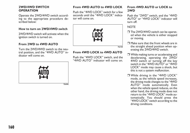
160
2WD/4WD SWITCHOPERATION
Operate the 2WD/4WD switch accord-ing to the appropriate procedure de-scribed below:
How to turn on 2WD/4WD switch
2WD/4WD switch will activate when theignition switch is turned on.
From 2WD to 4WD AUTO
Turn the 2WD/4WD switch to the neu-tral position, and the “4WD AUTO” in-dicator will come on.
79J040
From 4WD AUTO to 4WD LOCK
Push the “4WD LOCK” switch for a fewseconds until the “4WD LOCK” indica-tor will come on.
79J100
From 4WD LOCK to 4WD AUTO
Push the “4WD LOCK” switch, and the“4WD AUTO” indicator will come on.
From 4WD AUTO or LOCK to2WD
Push the “2WD” switch, and the “4WDAUTO” or “4WD LOCK” indicator willturn off.
NOTE
� The 2WD/4WD switch can be operat-ed when the vehicle is either stoppedor moving.
� Make sure that the front wheels are inthe straight ahead position when op-erating the 2WD/4WD switch.
� While making turns or accelerating anddecelerating, operating the 2WD/4WD switch or turning off the keyswitch in the “4WD AUTO” or “4WDLOCK” mode may cause a shock, butthis is not a system malfunction.
� While driving in the “4WD LOCK”mode, as the vehicle speed increases,the driving mode changes to the “4WDAUTO” mode automatically. Evenwhen the vehicle speed reduces, on theother hand, the driving mode does notreturn to the “4WD LOCK” mode au-tomatically. You should press the“4WD LOCK” switch according to thedriving conditions.
149-168 SEDICI LUM FL GB 1E 19-06-2009 13:33 Pagina 160

161
� Any forcible operation while driving of-froad in the sand or water or when awheel has run off the road, the differ-ence of the revolution between frontwheels and rear wheels increases(wheels run idle). If this state continues,the oil temperature of the driving sys-tem parts rises.In such case, the “4WD AUTO” indi-cator light blinks and the driving modechanges to the 2WD mode to protectthe driving system parts.When you operate your vehicle in the4WD mode continuously, park the ve-hicle at a safe place and run the engineidle. After some time, the “4WD AU-TO” indicator light turns on again andthe driving mode returns to the “4WDAUTO” mode.
IMPORTANT� Never use the “4WD LOCK” mode
when driving on dry paved roads.Avoid using the “4WD LOCK” modewhen driving on wet paved roads asmuch as possible. Use of the “4WDLOCK” mode in above conditions willapply excessive force to the driving sys-tem and may cause a critical failure. Also,the tires may wear faster and fuel con-sumption may be affected adversely.
BRAKING
The distance needed to bring any vehicleto a halt increases with the speed of thevehicle. The braking distance needed, forexample, at 60 km/h (37 mph) will be ap-proximately 4 times greater than the brak-ing distance needed at 30 km/h (19 mph).Start to brake the vehicle when there isplenty of distance between your vehicleand the stopping point, and slow downgradually.
60G165A
� Note that 4WD vehicles are not al-laround vehicles. Be sure to observefollowing instructions when drivingyour vehicle.– Do not drive through water like
crossing a river.– Do not drive continuously where
front wheels tend to race such as inthe sand and mud.
– When any wheel is in the air for suchreason as running off the road, donot race it needlessly.
� If the “4WD AUTO” and the “4WDLOCK” indicator lights stay on and comeon simultaneously when driving, theremay be something wrong the 4WD sys-tem. Have the system inspected by an au-thorized Fiat Dealership.
IMPORTANT Unevenly worn tires cancause problems in the operation of the2WD/4WD switch. Be sure to rotate thetires according to the maintenance sched-ule. Refer to “Tires” and “MaintenanceSchedule” in the “INSPECTION ANDMAINTENANCE” section for proper tirerotation procedures.
149-168 SEDICI LUM FL GB 1E 19-06-2009 13:33 Pagina 161

162
POWER-ASSISTED BRAKES
Your vehicle has power-assisted brakes. Ifpower assistance is lost due to a stalledengine or other failures, the system is stillfully operational on reserve power andyou can bring the vehicle to a completestop by pressing the brake pedal once andholding it down. The reserve power ispartly used up when you depress thebrake pedal and reduces each time thepedal is pressed. Apply smooth and evenpressure to the pedal. Do not pump thepedal.
ANTI-LOCK BRAKE SYSTEM(ABS) (for versions/markets, where provided)
ABS will help you avoid skidding by elec-tronically controlling braking pressure. Itwill also help you maintain steering con-trol when braking on slippery surfaces orwhen braking hard.
The ABS works automatically, so you donot need any special braking technique.
Just push the brake pedal down withoutpumping. The ABS will operate whenev-er it senses that the wheels are locking up.You may feel the brake pedal moves a lit-tle while the ABS is operating.
NOTE The ABS will not work if vehiclespeed is under about 6 km/h (4 mph).
If water gets into the brakedrums, brake performance
may become poor and unpredictable.After driving through water or wash-ing the underside of the vehicle, testthe brakes while driving at a slowspeed to see if they have maintainedtheir normal effectiveness. If thebrakes are less effective than normal,dry them by repeatedly applying thebrakes while driving slowly until thebrakes have regained their normal ef-fectiveness.
WARNING
Even without reserve powerin the brake system, you can
still stop the vehicle by pressing thebrake pedal harder than normally re-quired. However, the stopping dis-tance may be longer.
WARNING
Brake Assist System
When you slam the brakes on, the brakeassist system judges as an emergency stopand provides more powerful braking for adriver who cannot hold down the brakepedal firmly.
NOTE If you quickly and forcefully de-press the brakes, you may hear a clickingsound in the brake pedal. This is normaland indicates that the brake assist systemis activated properly.
149-168 SEDICI LUM FL GB 1E 19-06-2009 13:33 Pagina 162
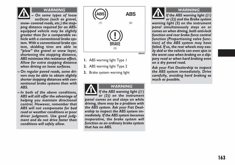
163
1. ABS warning light Type 1
2. ABS warning light Type 2
3. Brake system warning light
(1) (2)
(3)
65D451
– On some types of loosesurfaces (such as gravel,
snow- covered roads, etc.) the stop-ping distance required for an ABS-equipped vehicle may be slightlygreater than for a comparable ve-hicle with a conventional brake sys-tem. With a conventional brake sys-tem, skidding tires are able to“plow” the gravel or snow layer,shortening the stopping distance,ABS minimizes this resistance effect.Allow for extra stopping distancewhen driving on loose surfaces.
– On regular paved roads, some dri-vers may be able to obtain slightlyshorter stopping distances with con-ventional brake systems than withABS.
– In both of the above conditions,ABS will still offer the advantage ofhelping you maintain directionalcontrol. However, remember thatABS will not compensate for badroad or weather conditions or poordriver judgment. Use good judg-ment and do not drive faster thanconditions will safely allow.
WARNING
If the ABS warning light ((1)or (2)) on the instrument
panel comes on and stays on whiledriving, there may be a problem withthe ABS system. Ask your Fiat Deal-ership to inspect the ABS system im-mediately. If the ABS system becomesinoperative, the brake system willfunction as an ordinary brake systemthat has no ABS.
WARNING
If the ABS warning light ((1)or (2)) and the Brake system
warning light (3) on the instrumentpanel simultaneously stays on orcomes on when driving, both anti-lockfunction and rear brake force controlfunction (Proportioning valve func-tion) of the ABS system may havefailed. If so, the rear wheels may eas-ily skid or the vehicle can even spin inthe worst case when braking on a slip-pery road or when hard braking evenon a dry paved road.Ask your Fiat Dealership to inspectthe ABS system immediately. Drivecarefully, avoiding hard braking asmuch as possible.
WARNING
149-168 SEDICI LUM FL GB 1E 19-06-2009 13:33 Pagina 163

164
HOW THE ABS WORKS
A computer continuously monitors wheelspeed. The computer compares thechanges in wheel speed when braking. Ifthe wheels slow suddenly, indicating askidding situation, the computer willchange braking pressure several timeseach second to prevent the wheels fromlocking. When you start your vehicle orwhen you accelerate after a hard stop, youmay hear a momentary motor or clickingnoise as the system resets or checks itself.
The ABS may not workproperly if tires or wheels
other than those specified in the own-er’s manual are used. This is becausethe ABS works by comparing changesin wheel speed. When replacing tiresor wheels, use only the size and typespecified in this owner’s manual.
WARNING
ELECTRONIC STABILITYPROGRAM (ESP®)(for versions/markets, where provided)
ESP® is a registered trademark of DaimlerAG.
The Electronic Stability Program (ESP®)helps to control the vehicle during cor-nering if the vehicle is understeering oroversteering. It also assists you in main-taining traction while accelerating on looseor slippery road surfaces. It does this byregulating the engine’s output, and by se-lectively applying the brakes. In addition,ESP® helps to avoid skidding by controllingbraking pressure.
The ESP® cannot enhancethe vehicle’s driving stabili-
ty in all situations and does not con-trol your vehicle’s entire braking sys-tem. The ESP® cannot prevent acci-dents, including those resulting fromexcessive speed in turns, or hy-droplaning. Only a safe and attentivedriver can prevent accidents. The ca-pabilities of an ESP® - equipped ve-hicle must never be used as a substi-tute for careful driving.
WARNING
The ESP® has the following three systems:
STABILITY CONTROL SYSTEM
The vehicle stability control system helpsprovide integrated control of systems suchas anti- lock brakes, traction control, en-gine control, etc. This system automati-cally controls the brakes and engine tohelp prevent the vehicle from skiddingwhen cornering on a slippery road surfaceor when turning the steering wheelabruptly.
TRACTION CONTROL SYSTEM
The traction control system automatical-ly helps prevent the spinning of wheelswhen the vehicle is started or acceleratedon slippery road surfaces. The system op-erates only if it senses that some of thewheels are spinning or beginning to losetraction. When this happens, the systemoperates the front or rear brakes and re-duces engine power to limit wheel spin.
NOTE You may hear a clicking sound inthe engine compartment for a few secondswhen you start the engine or just after thevehicle begins to move. This means thatthe above systems are in the self-checkmode. This sound does not indicate a mal-function.
149-168 SEDICI LUM FL GB 1E 19-06-2009 13:33 Pagina 164

165
– The ESP may not workproperly if tires or wheels
other than those specified in theOwner’s Manual are used. When re-placing tires or wheels, use only thesize and type specified in this Own-er’s Manual.– The ESP® may not work properly iftires are not inflated to the recom-mended tire inflation pressure.– The ESP® may not work properly iftires are fitted with tire chains.– The ESP® may not work properly ifthe tires are excessively worn. Be sureto replace tires when the tread wearindicators in the grooves appear onthe tread surface.– The ESP® is not a substitute for win-ter tires or tire chains on a snow cov-ered road.
WARNING
– The ESP® may not workproperly if engine related
parts such as the muffler are notequivalent to standard equipment orare extremely deteriorated.– Do not modify the vehicle’s sus-pension since the ESP® may not op-erate correctly.
WARNING
ANTI-LOCK BRAKING SYSTEM(ABS)
ABS will help you avoid skidding by elec-tronically controlling braking pressure. Itwill also help you maintain steering con-trol when braking on slippery surfaces orwhen braking hard. The ABS works au-tomatically, so you do not have to use anyspecial braking technique. Just push thebrake pedal down without pumping. TheABS will operate whenever it senses thatwheels are locking up. You may feel thebrake pedal pulsate while the ABS is op-erating.(For more information on ABS, see “Brak-ing” in the “OPERATING YOUR VEHI-CLE” section.)
NOTE If the ABS system is activated, youmay hear a clunking noise and/ or feel pul-sating in the brake pedal. This is normaland indicates that the brake fluid pressureis being controlled properly.
The ESP® indicator lights are described be-low:
SLIP INDICATOR LIGHT
52KM133
When one of the ESP® systems other thanABS is activated, the SLIP indicator light inthe instrument cluster blinks 5 times persecond.
IMPORTANT If the SLIP indicator lightcomes on and stays on while driving, theremay be a malfunction of the ESP® systems(other than ABS). You should have thesystems inspected by an authorized FiatDealership.
NOTE When the SLIP indicator lightcomes on and stays on while driving, in-dicating a malfunction of the ESP® systems(other than ABS), the brake system willfunction as an ordinary ABS with no ad-ditional ESP® functions.
149-168 SEDICI LUM FL GB 1E 19-06-2009 13:33 Pagina 165

166
NOTE
When you disconnect and re- connect thebattery, ESP® system functions other thanABS will be deactivated and the slip indi-cator light will blink 1 time per second.In this case, use the following procedureto reactivate the ESP® systems:
� Drive your vehicle straight ahead with-out tire slippage at a speed greater thanapproximately 15 km/ h (9 mph) for afew seconds
� The slip indicator light will go out andthe ESP® systems (other than ABS) willbe re- activated
It may take more than few seconds beforethe slip indicator light goes out dependingon the road surface condition.
“ESP” Warning Light
IMPORTANT If the “ESP” warning lightcomes on, or stays on while driving, theremay be a malfunction of the ESP® systems(other than ABS). You should have thesystems inspected by an authorized FiatDealership.
NOTE When the “ESP” warning lightcomes on, or stays on while driving, indi-cating a malfunction of the ESP® systems(other than ABS), the brake system willfunction as an ordinary ABS that has noadditional ESP® functions.
“ESP OFF” Indicator Light
“ESP OFF” switch
When the “ESP OFF” switch located atthe center of the instrument panel ispushed and held to turn off the ESP® sys-tems (other than ABS), the “ESP OFF” in-dicator light in the instrument clustercomes on.
When you have turned the ESP® systems(other than ABS) off, make sure to turnthem back on before resuming ordinarydriving.
When you push and hold the “ESP OFF”switch again, the “ESP OFF” indicator lightwill go out and all of the ESP® systems willbe activated.
ABS Warning Light / BrakeSystem Warning Light
See “Braking” in the “OPERATINGYOUR VEHICLE” section.
66J031
When the ESP® systems (other than ABS)have a system malfunction, the “ESP”warning light in the instrument clustercomes on.
66J032
You should turn the ESP® on during yourordinary driving, so that you have the ben-efits of all of the ESP® systems.
It may be required to turn the ESP® sys-tems (other than ABS) off if your vehicleis stuck in sand, mud, or snow, wherewheel spin is necessary.
62J142
149-168 SEDICI LUM FL GB 1E 19-06-2009 13:33 Pagina 166

167
IMPORTANT To minimize the possibili-ty of catalyst or other vehicle damage:
� Maintain the engine in the proper op-erating condition.
� In the event of an engine malfunction,particularly one involving engine misfireor other apparent loss of performance,have the vehicle serviced promptly.
� Do not turn off the engine or interruptthe ignition when the transaxle is ingear and the vehicle is in motion.
� Do not try to start the engine by push-ing or towing the vehicle, or coastingdown a hill.
� Do not idle the engine with any sparkplug wires disconnected or removed,such as during diagnostic testing.
CATALYTIC CONVERTER(for versions/markets, where provided)
The purpose of the catalytic converter isto minimize the amount of harmful pollu-tants in your vehicle’s exhaust. Use ofleaded fuel in vehicles equipped with cat-alytic converters is prohibited, becauselead deactivates the pollutant- reducingcomponents of the catalyst system.
The converter is designed to last the lifeof the vehicle under normal usage andwhen unleaded fuel is used. No specialmaintenance is required on the convert-er. However, it is very important to keepthe engine properly tuned. Engine misfir-ing, which can result from an improperlytuned engine, may cause overheating ofthe catalyst. This may result in permanentheat damage to the catalyst and other ve-hicle components.
68KM085
RUNNING-IN
IMPORTANT The future performanceand reliability of the engine depends on thecare and restraint exercised during its ear-ly life. It is especially important to observethe following precautions during the initial960 km (600 miles) of vehicle operation.
� After starting, do not race the engine.Warm it up gradually.
� Avoid prolonged vehicle operation at aconstant speed. Moving parts will breakin better if you vary your speed.
� Start off from a stop slowly. Avoid fullthrottle starts.
� Avoid hard braking, especially duringthe first 320 km (200 miles) of driving.
� Do not drive slowly with the transaxlein a high gear.
� Drive the vehicle at moderate enginespeeds.
� Do not tow a trailer during the first960 km (600 miles) of vehicle opera-tion.
149-168 SEDICI LUM FL GB 1E 19-06-2009 13:33 Pagina 167

168
IMPROVING FUELECONOMY
The following instructions will help youimprove fuel economy.
Avoid excessive idling
If you are to wait for more than a minutewhile you are parked, stop the engine andstart it again later. When warming up acold engine, allow the engine to idle untilthe temperature gauge pointer comes upto the “C” position (if the idling is not pro-hibited). In this position, the engine is suf-ficiently warm for starting off.
Avoid “fast” starts
Fast starts away from lights or stop signswill consume fuel unnecessarily and short-en engine life. Start off slowly.
Avoid unnecessary stops
Avoid unnecessary deceleration and stop-ping. Try to maintain a slow, steady speedwhenever possible. Slowing down andthen accelerating again uses more fuel.
Keep a steady cruising speed
Keep as constant a speed as road and traf-fic conditions will permit.
Keep the air cleaner clean
If the air cleaner is clogged with dust, therewill be greater intake resistance, result-ing in decreased power output and in-creased fuel consumption.
Keep weight to a minimum
The heavier the load, the more fuel thevehicle consumes. Take out any luggage orcargo when it is not necessary.
Keep tire pressures correct
Underinflation of the tires can waste fueldue to increased running resistance of thetires. Keep your tires inflated to the cor-rect pressure shown on the label on thedriver’s side door or the driver’s doorlock pillar.
60A183S
� Do not idle the vehicle for prolongedperiods if idling seems rough or thereare other malfunctions.
� Do not allow the fuel tank to get nearthe empty level.
54G584S
Be careful where you parkand drive; the catalytic con-
verter and other exhaust componentscan get very hot. As with any vehicle,do not park or operate this vehiclein areas where combustible materialssuch as dry grass or leaves can comein contact with a hot exhaust system.
WARNING
149-168 SEDICI LUM FL GB 1E 19-06-2009 13:33 Pagina 168

169
DDRRIIVVIINNGG TTIIPPSS
60G409
HIGHWAY DRIVING.......................................................... 170
DRIVING ON HILLS ............................................................ 170
DRIVING ON SLIPPERY ROADS ..................................... 171
6
169-172 SEDICI LUM FL GB 1E 19-06-2009 10:47 Pagina 169

170
HIGHWAY DRIVING
When driving at high-speed, pay attentionto the following:
❒ Stopping distance progressively in-creases with vehicle speed. Apply thebrakes far enough ahead of the stoppingpoint to allow for the extra stoppingdistance.
❒ On rainy days, “Aquaplaning” can occur.“Aquaplaning” is the loss of direct con-tact between the road surface and thevehicle’s tires due to a water film form-ing between them. Steering or brakingthe vehicle while “Aquaplaning” can bevery difficult, and loss of control can oc-cur. Keep speed down when the roadsurface is wet.
❒ At high speeds, the vehicle may be af-fected by side winds. Therefore, reducespeed and be prepared for unexpect-ed buffeting, which can occur at the ex-its of tunnels, when passing by a cut ofa hill, or when being overtaken by largevehicles, etc.
DRIVING ON HILLS
❒ When climbing steep hills, the vehiclemay begin to slow down and show alack of power. If this happens, youshould shift to a lower gear so that theengine will again be operating in its nor-mal power range. Shift rapidly to pre-vent the vehicle from losing momen-tum.
❒ When driving down a hill, the engineshould be used for braking by shiftinginto a lower gear. (Do this with EITHERan automatic or manual transaxle.)
52D078S
– Wear Your Seat Belts at AllTimes. Even though air bags
are equipped at the front seating po-sitions, the driver and all passengersshould be properly restrained at alltimes, using the seat belts provided.Refer to the “Seat Belts and Child Re-straint Systems” section for instruc-tions on proper use of the seat belts.– Never drive while under the influ-ence of alcohol or other drugs. Alco-hol and drugs can seriously impairyour ability to drive safely, greatly in-creasing the risk of injury to yourselfand others. You should also avoid dri-ving when you are tired, sick, irritat-ed, or under stress.
WARNING
Try not to hold the brakepedal down too long or too
often while going down a steep orlong hill. This could cause the brakesto overheat, resulting in reducedbraking efficiency. Failure to take thisprecaution could result in loss of ve-hicle control.
WARNING
169-172 SEDICI LUM FL GB 1E 19-06-2009 10:47 Pagina 170

171
DRIVING ON SLIPPERYROADS
Under wet road conditions you shoulddrive at a lower speed than on dry roadsdue to possible slippage of tires duringbraking. When driving on icy, snow-cov-ered, or muddy roads, reduce your speedand avoid sudden acceleration, abruptbraking, or sharp steering movements.
FOR 4-WHEEL DRIVE (4WD)MODELS
Your 4WD is designed to get better trac-tion on slippery roads than 2-wheel drivemodels. However, your 4WD will nothave as much traction in deep snow, mudor sand as multipurpose 4WD vehicles.You should not attempt to drive your4WD in deep snow, mud or sand. 4WDmodels are not sport/utility vehicles, andare not designed for off-road use.
SNOW CHAINS
Snow chains should only be used if theyare needed to increase traction or are re-quired by law. Make sure that the chainsyou use are the correct size for your ve-hicle’s tires. Also make sure that there isenough clearance between the fendersand the chains as installed on the tires.
Install the chains on the front tires tight-ly, according to the chain manufacturer’sinstructions. Retighten the chains after dri-ving about 1. 0 km (1/ 2 mile) if necessary.With the chains installed, drive slowly.
IMPORTANT
❒ If you hear the chains hitting against thevehicle body while driving, stop andtighten them.
❒ If you vehicle is equipped with full wheelcaps, remove the wheel caps before in-stalling the chains or the wheel caps canbe damaged by the chain bands.
IMPORTANT When descending a downhill, NEVER turn the ignition key to the“OFF” position. Emission control systemdamage may result.
79J029 60G089S
169-172 SEDICI LUM FL GB 1E 19-06-2009 10:47 Pagina 171

172
IMPORTANT Do not continue rockingthe vehicle for more than a few minutes.Prolonged rocking can cause engine over-heating or transaxle damage.
IF YOUR VEHICLE GETS STUCK
If your vehicle gets stuck in snow, mud, orsand, follow the directions below:
❒ Shift the transaxle back and forth be-tween first gear and reverse. This willcreate a rocking motion which may giveyou enough momentum to free the ve-hicle. Press gently on the accelerator tokeep wheel spin to a minimum.Remove your foot from the accelera-tor while shifting.Do not race the engine. Excessivewheel spin will cause the tires to digdeeper, making it more difficult to freethe vehicle.
❒ If your vehicle remains stuck after a fewminutes of rocking, get another vehicleto pull you out.
Do not allow anyone tostand near the vehicle when
you are rocking it, and do not spin thewheels faster than an indicated 40 km/h (25 mph) on the speedome-ter. Personal injury and/ or vehicledamage may result from spinning thewheels too fast.
WARNING
54G638S
In addition to following thedriving tips in this section, it
is important to observe the followingprecautions.– Make sure your tires are in goodcondition and always maintain thespecified tire pressure. Refer to“Tires” in the “INSPECTION ANDMAINTENANCE” section for details.
WARNING
– Do not use tires other thanthose specified by Fiat.
Never use different sizes or types oftires on the front and rear wheels. Forinformation regarding the specifiedtires, refer to the Tire Information La-bel located on the driver’s door lockpillar.– Never use oversized tires or specialshock absorbers and springs to raise(jack up) your vehicle. This willchange the handling characteristics.Oversized tires may also rub againstthe fender over bumps, causing vehi-cle damage or tire failure.– After driving through water, test thebrakes while driving at a slow speedto see if they have maintained theirnormal effectiveness. If the brakes areless effective than normal, dry themby repeatedly applying the brakeswhile driving slowly until the brakeshave regained their normal effective-ness.
WARNING
169-172 SEDICI LUM FL GB 1E 19-06-2009 10:47 Pagina 172

173
VVEEHHIICCLLEE LLOOAADDIINNGG AANNDD TTOOWWIINNGG
54G215
VEHICLE LOADING ............................................................ 174
TRAILER TOWING.............................................................. 174
TOWING YOUR VEHICLE (RECREATIONAL TOWING)........................................... 179
7
173-182 SEDICI LUM FL GB 1E 19-06-2009 10:48 Pagina 173

174
TRAILER TOWING
Your Fiat was originally designed to car-ry people and a normal amount of cargo,not to tow a trailer. Fiat does not rec-ommend you use your vehicle to tow atrailer if there is not any local regulationabout towing capacity permitted (for ex-ample, registered or statutory towing ca-pacity). Towing a trailer can adversely af-fect handling, durability, and fuel economy.
Some countries have regulations whichspecifically allow trailer towing up to aspecified maximum trailer weight (regis-tered or statutory towing capacity,whichever is smaller); vehicles sold inthese countries can be used to tow a lighttrailer, provided the trailer does not ex-ceed the maximum trailer weight specifiedin the country’s regulations.
If you use your Fiat to tow a trailer, youshould always observe the requirementsand recommendations in this section. Ifyou intend to tow a trailer, it is essentialto select a trailer and trailer towing equip-ment which are compatible. A reputabletowing specialist can help you.
VEHICLE LOADING
Your vehicle was designed for specificweight capacities. The weight capacities ofyour vehicle are indicated by the GrossVehicle Weight Rating (GVWR) and theGross Axle Weight Rating (GAWR, frontand rear). The GVWR and GAWR (frontand rear) are listed in the “SPECIFICA-TIONS” section.
GVWR – Maximum permissible overallweight of the fully loaded vehicle (includ-ing all the occupants, accessories and car-go plus the trailer nose weight if towinga trailer).
GAWR – (Front and Rear) Maximum per-missible weight on an individual axle.
Actual weight of the loaded vehicle and ac-tual loads at the front and rear axles canonly be determined by weighing the vehi-cle. Compare these weights to the GVWRand GAWR (front and rear). If the grossvehicle weight or the load on either axleexceeds these ratings, you must removeenough weight to bring the load down tothe rated capacity.
Never overload your vehicle.The gross vehicle weight
(sum of the weights of the vehicle, allthe occupants, accessories, cargo plustrailer nose weight if towing a trailer)must never exceed the Gross VehicleWeight Rating (GVWR). In addition,never distribute a load so that theweight on either the front or rear axleexceeds the Gross Axle Weight Rat-ing (GAWR).
WARNING
Always distribute cargoevenly. To avoid personal in-
jury or damage to your vehicle, al-ways secure cargo to prevent it fromshifting if the vehicle moves sudden-ly. Place heavier objects on the floorand as far forward in the cargo areaas possible. Never pile cargo higherthan the top of the seat backs.
WARNING
173-182 SEDICI LUM FL GB 1E 19-06-2009 10:48 Pagina 174
Never use a tow bar whichattaches to the axle or the
bumper of your vehicle.
WARNING
Never attach safety chainsto the bumper of your vehi-
cle. Secure connections so that theycan’t come loose.
WARNING
Never connect trailer lightsdirectly into your vehicle’s
electrical system, or electrical systemdamage may occur.
WARNING
BRAKES
If trailer brakes are used, youshould follow all instructions
provided by the manufacturer. Nev-er connect to the brake system ofyour vehicle and never take an elec-trical supply directly from the wiringharness.
WARNING
175
SAFETY CHAINS
Always attach safety chains between yourvehicle and trailer. Cross safety chains un-der the nose of the trailer so that the nosewill not drop to the road if the trailer be-comes separated from the tow bar. Fol-low the manufacturer’s recommendationfor attaching safety chains. Always leavejust enough slack to permit full turning.Never allow safety chains to drag on theroad.
TRAILER LIGHTS
Make sure your trailer is equipped withlights which meet local requirements. Al-ways check for the proper operation of alltrailer lights before you start to tow.
IMPORTANT Trailer towing puts addi-tional stress on the engine, drive train, andbrakes of your vehicle. Never tow a trail-er during the first 960 km (600 miles) ofvehicle operation.
IMPORTANT For Automatic Transaxlevehicles, do not use “D” range when tow-ing on a steep hill. Towing in “D” rangewhen driving on a steep hill can cause au-tomatic transaxle fluid overheating with-out warning, which can result in transaxledamage.
TOW BARS
Only use a tow bar that is designed to at-tach to the chassis of your vehicle, anda hitch that is designed to bolt to thisbracket.
173-182 SEDICI LUM FL GB 1E 19-06-2009 10:49 Pagina 175

176
MIRRORS
Check to see if your vehicle’s mirrorsmeet local requirements for mirrors usedon towing vehicles. If they do not, youmust install the required mirrors beforeyou tow.
VEHICLE/TRAILER LOADING
To load your vehicle and trailer proper-ly, you must know how to measure grosstrailer weight and trailer nose weight.
Gross Trailer Weight is the weight of thetrailer plus all the cargo in it. You can mea-sure gross trailer weight by putting the ful-ly loaded trailer on a vehicle scale.
Nose Weight is the downward force ex-erted on the tow bar by the trailer cou-pler, with the trailer fully loaded and thecoupler at its normal towing height. Thisweight can be measured using a bathroomscales.
The weight of your loaded trailer (GrossTrailer Weight) should never exceed the“Towing capacity”.
Distribute cargo in your trailer so thatnose weight is about 10% of gross trailerweight, but does not exceed “Maximumvertical load on trailer hitch point”. Youshould measure gross trailer weight andnose weight before towing to make surethat your load is properly distributed.
TIRES
When towing a trailer, it isvery important for your ve-
hicle and trailer to have properly in-flated tires. Your vehicle’s tires shouldbe inflated to the pressures listed onyour vehicles Tire Information label.If laden pressures are listed on the la-bel, the tires should be inflated to theladen pressures. Inflate trailer tiresaccording to the specifications pro-vided by the trailer manufacturer.
WARNING
Improper weight distributionof your trailer may result in
poor vehicle handling and swaying ofthe trailer. Always make sure thattrailer nose weight is about 10% ofgross trailer weight, but does not ex-ceed “Maximum vertical load ontrailer hitch point”. Also make surethat the cargo is properly secured.Failure to observe this requirementmay result in an accident.
WARNING
173-182 SEDICI LUM FL GB 1E 19-06-2009 10:49 Pagina 176

177
ADDITIONAL TRAILERTOWING WARNINGS
Never overload your traileror your vehicle. Gross trail-
er weight must never exceed the“Towing capacity”. Gross vehicleweight (sum of the weights of the ve-hicle, all the occupants, accessoriesincluding tow bars and a trailer hitch,cargo and trailer nose weight) mustnever exceed the Gross VehicleWeight Rating (GVWR) listed in the“SPECIFICATIONS” section.
WARNING
Connect trailer lights andhook up safety chains every
time you tow.
WARNING
IMPORTANT Because towing a trailerputs additional stress on your vehicle,more frequent maintenance will be re-quired than under normal driving condi-tions. Follow the schedule for “Mainte-nance Recommended under Severe Dri-ving Conditions”.
Your vehicle will handle dif-ferently when towing a trail-
er. For your safety and the safety ofothers, you should observe the fol-lowing precautions:– Practice turning, stopping, and re-versing before you begin towing intraffic. Do not tow in traffic until youare confident that you can handle thevehicle and trailer safely.– Never exceed towing speed limits or80 km/h (50 mph), whichever is low-er.– Never drive at a speed that causesshaking or swaying of the trailer. Ifyou notice even the slightest sign ofshaking or swaying, slow down.– When roads are wet, slippery orrough, drive at a slower speed thanyou would on dry, smooth roads.Failure to slow down when road con-ditions are bad can result in loss ofcontrol.– Always have someone guide youwhen reversing.– Allow adequate stopping distance.Stopping distance is increased whenyou tow a trailer. For each 16 km/h(10 mph) of speed, allow at least onevehicle and trailer length betweenyou and the vehicle ahead. Follow ata greater distance if roads are wet orslippery.
WARNING– If the trailer has over-runbrakes, apply the brakes
gradually to avoid snatching causedby the trailer wheels locking.– Slow down before corners andmaintain a steady speed while cor-nering. Deceleration or accelerationwhile cornering can result in loss ofcontrol. Remember that a larger thannormal turning radius is needed be-cause the trailer wheels will be clos-er than vehicle wheels to the inside ofthe turn.– Avoid sudden acceleration andstopping of the vehicle. Do not makequick maneuvers unless they are nec-essary.– Slow down in cross winds and beprepared for gusts of wind from largepassing vehicles.– Be careful when overtaking othervehicles. Be sure to allow enoughroom for your trailer before youchange lanes, and signal well in ad-vance.– Slow down and shift into a lowergear before you reach long or steepdownhill grades. It is hazardous to at-tempt downshifting while you are de-scending a hill.
WARNING
173-182 SEDICI LUM FL GB 1E 19-06-2009 10:49 Pagina 177

178
– Avoid “riding” the brakes.This could cause the brakes
to overheat resulting in reduced brak-ing efficiency. Use engine braking asmuch as possible.– Because of the added trailer weight,your engine may overheat on hotdays when going up long or steephills. Pay attention to your enginetemperature gauge. If it indicatesoverheating, pull off the road andstop in a safe place. Refer to “If theEngine Overheats” in “EMERGENCYSERVICE” section.
WARNING
60A186
When parking your vehicleand connected trailer, al-
ways use the following procedure:– Apply the vehicle’s brakes firmly.– Have another person place wheelchocks under the wheels of the vehi-cle and the trailer while you are hold-ing the brakes.– Slowly release the brakes until thewheel chocks absorb the load.– Fully engage the parking brake.– Manual Transaxle – Shift into Re-verse or first gear and turn off the en-gine.– Automatic Transaxle – Shift intoPark and turn off the engine.
WARNING
When starting out afterparking:
– Depress the clutch and start the en-gine.– Shift into gear, release the parkingbrake, and slowly pull away from thechocks.– Stop, apply the brakes firmly andhold them.– Have another person remove thechocks.
WARNING
173-182 SEDICI LUM FL GB 1E 19-06-2009 10:49 Pagina 178

179
TOWING YOURVEHICLE(RECREATIONALTOWING)
Your vehicle may be towed behind an-other vehicle (such as a motorhome), pro-vided you use the proper towing methodspecified for your vehicle. The towingmethod you must use depends on thespecifications of your vehicle: whether itis a 2-wheel drive (2WD) vehicle or a 4-wheel drive (4WD) vehicle.
Use the towing instruction table to selectthe proper towing method for your vehi-cle, and carefully follow the correspond-ing instructions. Be sure to use propertowing equipment designed for recre-ational towing and make sure that tow-ing speed does not exceed 90 km/h (55mph).
Registered maximum vertical loadon trailer hitch point (EU)
50 kg (110 lbs)
Maximum permissible overhang “a”
810 mm (31.9 in.)
When you tow your vehicle,follow the instructions below
to avoid accidents and damage toyour vehicle. In addition, be sure toobserve government and local re-quirements regarding vehicle lightingand trailer hitches or tow bars.
WARNING
A safety chain should alwaysbe used when you tow your
vehicle.
WARNING
79J158
IMPORTANT Towing an automatictransaxle vehicle with four wheels on theground can result in damage to the auto-matic transaxle.
173-182 SEDICI LUM FL GB 1E 19-06-2009 10:49 Pagina 179

180
A: 2WD (EXCEPT 2WD MODEOF 4WD) VEHICLES WITHMANUAL TRANSAXLE ORAUTOMATIC TRANSAXLE
❒ Secure the front wheels on a towingdolly according to the instructions pro-vided by the dolly manufacturer.
❒ Release the parking brake.
54G212
TOWING METHOD AFROM THE FRONT:FRONT WHEELS ON A DOLLYAND REAR WHEELS ON THE GROUND
TOWING INSTRUCTION TABLE
DRIVE TRAIN
2WD
4WDincluding2WD mode
TOWINGMETHOD
A
A B
B
TRANSAXLE
A/T
M/T
M/T
54G641
173-182 SEDICI LUM FL GB 1E 19-06-2009 10:49 Pagina 180

181
79J130
TOWING METHOD BFROM THE FRONT:FOUR WHEELS ON THE GROUND
B: 2WD (EXCEPT 2WD MODEOF 4WD) VEHICLES WITHMANUAL TRANSAXLE
❒ Shift the manual transaxle lever intoneutral.
❒ Turn the ignition key to the “ACC” po-sition to unlock the steering wheel.
❒ Release the parking brake.
IMPORTANT The steering column is notstrong enough to withstand shocks trans-mitted from the front wheels during tow-ing. Always unlock the steering wheel be-fore towing.
173-182 SEDICI LUM FL GB 1E 19-06-2009 10:49 Pagina 181

182
B: 4WD (INCLUDING 2WDMODE OF 4WD) VEHICLESWITH MANUAL TRANSAXLE
IMPORTANT Do not tow the 4WD vehi-cle with either front wheels or rear wheelsdirectly on the ground (and the transaxlein neutral). If you do, the transaxle will bedamaged fatally.
❒ Shift the 2WD/4WD switch to the“2WD” mode.
❒ Shift the manual transaxle lever intoneutral.
❒ Turn the ignition key to the “ACC”position to unlock the steering wheel.
❒ Release the parking brake.
IMPORTANT The steering column isnot strong enough to withstand shockstransmitted from the front wheels dur-ing towing. Always unlock the steeringwheel before towing.
79J175
79J176
173-182 SEDICI LUM FL GB 1E 19-06-2009 10:49 Pagina 182

183
IINNSSPPEECCTTIIOONN AANNDD MMAAIINNTTEENNAANNCCEE
60G410
MAINTENANCE SCHEDULE................................................. 185
SERVICE SCHEDULE – PETROL VERSIONS..................... 186
SERVICE SCHEDULE – DIESEL VERSIONS........................ 188
MAINTENANCE RECOMMENDED UNDER SEVERE DRIVING CONDITIONS......................................................... 190
DRIVE BELT.................................................................................. 191
ENGINE OIL AND FILTER...................................................... 191
GEAR OIL...................................................................................... 195
AUTOMATIC TRANSAXLE (AT) FLUID ........................... 196
ENGINE COOLANT................................................................. 198
WINDSHIELD WASHER FLUID............................................ 201
AIR CLEANER.............................................................................. 201
SPARK PLUGS (Gasoline engine) ........................................... 202
FUEL FILTER (Diesel engine).................................................... 204
BRAKES.......................................................................................... 205
STEERING ..................................................................................... 207
CLUTCH PEDAL ........................................................................ 208
TIRES............................................................................................... 208
BATTERY....................................................................................... 213
FUSES.............................................................................................. 215
BULB REPLACEMENT............................................................... 221
WINDSCREEN - REAR WINDOW WASHER/WIPERS 227
AIR CONDITIONING SYSTEM............................................. 230
8
183-230 SEDICI LUM FL GB 1E 19-06-2009 11:00 Pagina 183

184
60B128S
You should take extremecare when working on your
vehicle to prevent accidental injury.Here are a few precautions that youshould be especially careful to ob-serve:– To prevent damage or unintendedactivation of the air bag system orseat belt pretensioner system, be surethe battery is disconnected and theignition switch has been in the“LOCK” position for at least 90 sec-onds before performing any electricalservice work on your Fiat. Do nottouch air bag system components,seat belt pretensioner system com-ponents or wires.The wires are wrapped with yellowtape or yellow tubing, and the cou-plers are yellow for easy identifica-tion.– Do not leave the engine running ingarages or other confined areas.
WARNING
– When the engine is run-ning, keep hands, clothing,
tools, and other objects away fromthe fan and drive belt. Even thoughthe fan may not be moving, it can au-tomatically turn on without warning.– When it is necessary to do servicework with the engine running, makesure that the parking brake is set ful-ly and the transaxle is in Neutral (formanual transaxle vehicles) or Park(for automatic transaxle vehicles).– Do not touch ignition wires or oth-er ignition system parts when startingthe engine or when the engine is run-ning, or you could receive an electricshock.– Be careful not to touch a hot en-gine, exhaust manifold and pipes,muffler, radiator and water hoses.– Do not allow smoking, sparks, orflames around gasoline or the bat-tery. Flammable fumes are present.– Do not get under your vehicle if it issupported only with the portable jackprovided in your vehicle.
WARNING– Be careful not to cause ac-cidental short circuits be-
tween the positive and negative bat-tery terminals.– Keep used oil, coolant, and otherfluids away from children and pets.Dispose of used fluids properly; nev-er pour them on the ground, into sew-ers, etc.
WARNING
183-230 SEDICI LUM FL GB 1E 19-06-2009 11:00 Pagina 184

185
MAINTENANCESCHEDULE
The following table shows the times whenyou should perform regular maintenanceon your vehicle. This table shows in miles,kilometers and months when you shouldperform inspections, adjustments, lubri-cation and other services. These intervalsshould be shortened if driving is usuallydone under severe conditions (refer to“Maintenance Recommended under Se-vere Driving Conditions”).
IMPORTANT The Programmed Mainte-nance coupons are specified by the Man-ufacturer. The failure to have them car-ried out may invalidate the warranty.
IMPORTANT Whenever it becomes nec-essary to replace parts on your vehicle,it is recommended that you use genuineFiat replacement parts.
Vehicle maintenance shouldbe entrusted to Fiat Dealer-
ship. For routine and minor mainte-nance operations you wish to carryout yourself, always make sure youhave the proper equipment, genuineFiat spare parts and the necessary flu-ids; do not however carry out theseoperations if you have no experience.
WARNINGThe shock absorbers arefilled with high pressure gas.
Never attempt to disassemble it orthrow it into a fire. Avoid storing itnear a heater or heating device.When scrapping the absorber, the gasmust be released from the absorbersafely. Ask your Fiat Dealership for as-sistance.
WARNING
183-230 SEDICI LUM FL GB 1E 19-06-2009 11:00 Pagina 185

186
15 30 45 60 75 90 105 120 135 150 165 180
● ● ● ● ● ● ● ● ● ● ● ●
● ● ● ● ● ● ● ● ● ● ● ●
● ● ● ● ● ● ● ● ● ● ● ●
● ● ● ● ● ● ● ● ● ● ● ●
● ● ● ● ● ● ● ● ● ● ● ●
● ● ● ● ● ●
● ● ● ● ● ● ● ● ● ● ● ●
● ● ● ● ● ● ● ● ● ● ● ●
● ●
● ●
● ● ● ● ● ● ● ● ● ● ● ●
● ● ● ● ● ●
● ● ● ● ● ●
SERVICE SCHEDULE - PETROL VERSIONS
Service coupons shall be carried out every 15,000 km
Thousands of km
Check tyre condition/wear and adjust pressure, if required
Check lighting system operation (headlights, direction indicators, hazard lights, passenger compartment lights, boot lights, instrument panel warning lights, etc.)
Check windscreen wiper/washer operation and adjust nozzles, if required
Check the position/wear of the windscreen/rearscreen wiper blades
Check condition and wear of front disc brake pads and brake pad wear indication
Check rear disc brake pad or shoes condition and wear
Visually inspect the condition of: bodywork, underbody protection, pipes and hoses (exhaust - fuel - brakes), rubber parts (gaiters, sleeves, bushes, etc.)
Check and top up, if required, fluid levels (brake/hydraulic clutch fluid, windscreen washer fluid, battery fluid, engine coolant, etc.)
Visually inspect condition of auxiliary drive belt
Check antievaporation system
Check the handbrake lever travel and adjust it, if required
Check and adjust tappet clearance, if required
Check exhaust emissions
183-230 SEDICI LUM FL GB 1E 19-06-2009 11:00 Pagina 186

187
15 30 45 60 75 90 105 120 135 150 165 180
● ● ● ● ● ● ● ● ● ● ● ●
● ● ● ●
● ● ● ● ● ● ● ● ● ● ● ●
● ● ● ● ● ● ● ●
● ● ● ●
● ● ● ●
● ●
● ● ● ●
●
● ● ● ● ●
● ● ● ●
●
● ● ● ● ● ●
● ● ● ●
●
● ● ● ● ● ●
● ● ● ● ● ●
● ● ● ● ● ●
● ● ● ● ● ●
● ● ● ● ● ●
Thousands of km
Check cleanliness of locks, bonnet and boot, and cleanliness and lubrication of linkages
Replace spark plugs (replace iridium spark plugs every 105,000 km) or every 7 years
Change engine oil and oil filter
Check air cleaner conditions
Replace air filter cartridge
Change engine coolant
Replace auxiliary drive belt
Sight inspect fuel tank conditions
Check manual transaxle gear oil level
Check automatic transaxle gear oil level
Change manual transaxle gear oil
Change automatic transaxle gear oil
Check transmission unit oil level (4x4 version)
Check rear differential oil level (4x4 version)
Change rear differential oil (4x4 version) (just the first time at 15,000 km)
Check suspension operation
Check steering system
Check engine management system operation (via diagnostic socket)
Change brake and clutch fluid (or every 2 years)
Replace pollen filter (or every 2 years)
183-230 SEDICI LUM FL GB 1E 19-06-2009 11:00 Pagina 187

188
15 30 45 60 75 90 105 120 135 150 165 180
● ● ● ● ● ● ● ● ● ● ● ●
● ● ● ● ● ● ● ● ● ● ● ●
● ● ● ● ● ● ● ● ● ● ● ●
● ● ● ● ● ● ● ● ● ● ● ●
● ● ● ● ● ● ● ● ● ● ● ●
● ● ● ● ● ●
● ● ● ● ● ● ● ● ● ● ● ●
● ● ● ● ● ● ● ● ● ● ● ●
● ●
● ● ● ● ● ●
● ● ● ● ● ●
● ● ● ● ● ● ● ● ● ● ● ●
SERVICE SCHEDULE - DIESEL VERSIONS
Service coupons shall be carried out every 15,000 km
Thousands of km
Check tyre condition/wear and adjust pressure, if required
Check lighting system operation (headlights, direction indicators, hazard lights, passenger compartment lights, boot lights, instrument panel warning lights, etc.)
Check windscreen wiper/washer operation and adjust nozzles, if required
Check the position/wear of the windscreen/rearscreen wiper blades
Check condition and wear of front disc brake pads and brake pad wear indication
Check rear disc brake pad or shoes condition and wear
Visually inspect the condition of: bodywork, underbody protection, pipes and hoses (exhaust - fuel - brakes), rubber parts (gaiters, sleeves, bushes, etc.)
Check and top up, if required, fluid levels (brake/hydraulic clutch fluid, windscreen washer fluid, battery fluid, engine coolant, etc.)
Visually inspect condition of auxiliary drive belt
Check the handbrake lever travel and adjust it, if required
Check exhaust emissions
Check cleanliness of locks, bonnet and boot, and cleanliness and lubrication of linkages
183-230 SEDICI LUM FL GB 1E 19-06-2009 11:00 Pagina 188

189
15 30 45 60 75 90 105 120 135 150 165 180
● ● ● ● ● ● ● ●
● ● ● ●
● ● ● ●
●
●
● ● ●
● ● ● ●
●
● ● ● ●
● ● ● ● ● ●
● ● ● ● ●
●
● ● ● ● ● ●
● ● ● ● ● ●
● ● ● ● ● ●
● ● ● ● ● ●
● ● ● ● ● ●
Thousands of km
Change engine oil and oil filter (DPF versions) (**)
Check air cleaner conditions
Replace air filter cartridge
Change engine coolant
Replace auxiliary drive belt
Replace timing belt (*)
Replace fuel filter (or every 4 years)
Sight inspect fuel tank conditions
Check manual transaxle gear oil level
Change manual transaxle gear oil
Check transmission unit oil level (4x4 version)
Check rear differential oil level (4x4 version)
Change rear differential oil (4x4 version) (just the first time at 15,000 km)
Check suspension operation
Check steering system
Check engine management system operation (via diagnostic socket)
Change brake and clutch fluid (or every 2 years)
Replace pollen filter (or every 2 years)
(*) Regardless of the number of kilometres covered, the timing belt should be replaced every 4 years for particularly demanding use(cold climates, driving in the city, idling for a long time) or in any case every 5 years.
(**) The engine oil and oil filter should be changed when the warning light on the dashboard comes on, or every 2 years.
183-230 SEDICI LUM FL GB 1E 19-06-2009 11:00 Pagina 189

MAINTENANCE RECOMMENDED UNDER SEVERE DRIVING CONDITIONSIf the vehicle is usually used under the conditions corresponding to any severe condition code given below, it is recommended thatapplicable maintenance operation be performed at the particular interval as given in the chart below.
190
G ----H Trailer towing (if admitted)
Maintenance OperationI Inspect and correct or replace if necessaryR Replace or Change
NOTE 4WD: 4-wheel drive
Severe condition codeA Repeated short tripsB Driving on rough and/or muddy roadsC Driving on dusty roadsD Driving in extremely cold weather and/or salted roadsE Repeated short trips in extremely cold weatherF Leaded fuel use
Severe Condition Code
B C D
A D
A C D E F H
A C D E H
A B C E F H
C
B E H
B C D H
B D E H
B E H
C D
Maintenance Interval
Every 15,000 km (9,000 miles) or 12 months
Every 45,000 km (27,000 miles) or 36 months
Every 36 monthsEvery 7,500 km (4,500 miles) or 6 months
Every 7,500 km (4,500 miles) or 6 months
Every 30,000 km (18,000 miles) or 24 months
Every 10,000 km (6,000 miles) or 8 months
Every 2,500 km (1,500 miles)
Every 30,000 km (18,000 miles) or 24 months
Every 30,000 km (18,000 miles) or 24 months
Every 15,000 km (9,000 miles) or 12 months
Every 15,000 km (9,000 miles) or 12 months
First time only: 15,000 km (9,000 miles) or 12 monthsSecond time and after: Every 30,000 km (18,000 miles) or 24 months reckoning from 0 km (0 mile) or 0 month
Every 15,000 km (9,000 miles) or 12 months
Every 45,000 km (27,000 miles) or 36 months
Maintenance
Engine accessory drive belt (V-rib belt)
Camshaft timing belt (Diesel engine)
Engine oil and oil filter (Gasoline engine)
Engine oil and oil filter (Diesel engine)
Spark plugs
Air cleaner filter element (Inspect or replace more frequently if necessary)
Automatic transaxle fluid change
Wheel bearings
Drive axle boots/Propeller shaft (4WD)
Manual transaxle oil/Transfer oil (4WD)Differential oil (4WD)
Air conditioner filter element (for versions/markets, where provided) (Clean more frequently if the air flow from the air conditioner decreases)
MaintenanceOperation
I
RRR
R
R
R
I
R
R
I
I
R
I
R
Iridium plug (Highly recommended)
Nickel plug (Standard type)
183-230 SEDICI LUM FL GB 1E 19-06-2009 11:00 Pagina 190

191
ENGINE OIL AND FILTER
OIL SPECIFICATIONS -GASOLINE ENGINES
Check whether the adopted engine oil isfalling within the following quality classes:API SL, SM or ACEA A3, recommendedproduct: SELENIA K SAE 5W-40, Fiat9.55535-M2 qualification.
OIL SPECIFICATIONS -DIESEL ENGINES
Check whether the adopted engine oil isfalling within the following quality classes:API CF or ACEA B4, recommended product: SELENIA WR SAE 5W-40, Fiat 9.55535-N2 qualification.
DRIVE BELT
63J132
DEF: 4.5 – 5.5 mm(0.18 – 0.22 in.)
DEF: 3 – 5 mm(0.12 – 0.20 in.)
DEF: 7 – 8 mm(0.28 – 0.31 in.)
AC
GE
→ : 100 N (10 kg, 22 lbs) press GE: GeneratorDEF: DeflectionAC: Air conditioner compressor
When the engine is running,keep hands, hair, clothing,
tools, etc. away from the moving fanand drive belts.
WARNING
For Gasoline Engine Model
Make sure the drive belt tension is cor-rect. If the belt is too loose, insufficientbattery charging, engine overheating, poorpower steering, poor air conditioning, orexcessive belt wear can result. When youpress the belt with your thumb midwaybetween the pulleys, there should be a de-flection according to the following chart.
The belts should also be examined to en-sure that they are not damaged.
If you need to replace or adjust the belthave it done by your Fiat Dealership.
For Diesel Engine Model
The drive belts tension is adjusted auto-matically.
183-230 SEDICI LUM FL GB 1E 19-06-2009 11:00 Pagina 191

192
1. MIN
2. MAX
3. Engine oil dipstick
IMPORTANT Failure to check the oil lev-el regularly could lead to serious enginetrouble due to insufficient oil.
REFILLING
Remove the oil filler cap and pour oilslowly through the filler hole to bring theoil level to the upper limit on the dipstick.Be careful not to overfill. Too much oil isalmost as bad as too little oil. After refill-ing, start the engine and allow it to idle forabout a minute. Stop the engine, waitabout 5 minutes and check the oil levelagain.
OIL LEVEL CHECK
It is important to keep the engine oil at thecorrect level for proper lubrication ofyour vehicle’s engine. Check the oil levelwith the vehicle on a level surface. The oillevel indication may be inaccurate if thevehicle is on a slope. The oil level shouldbe checked either before starting the en-gine or at least 5 minutes after stoppingthe engine.
The handle of the engine oil dipstick is col-ored yellow for easy identification. Pull outthe oil dipstick, wipe oil off with a cleancloth, insert the dipstick all the way intothe engine, then remove it again. The oilon the stick should be between the upperand lower limits shown on the stick. If theoil level indication is near the lower limit,add enough oil to raise the level to the up-per limit.
80G064 81A147
Open Close
For Gasoline Engine Model
(3)
(2) (1)
79J170
For Diesel Engine Model
183-230 SEDICI LUM FL GB 1E 19-06-2009 11:00 Pagina 192

193
Tightening torque for drain plugFor Gasoline Engine Model: 35 Nm (3.5 kgm, 25.3 lb·ft)For Diesel Engine Model:20 Nm (2,0 kgm, 14.4 lb-ft)
❒ Reinstall the drain plug and gasket.Tighten the plug with a wrench to thespecified torque.
NOTE (For Diesel Engine Model)Whenever the engine oil is changed, themonitoring system to find the next oilchange stage must be reset whether theoil pressure light blinks or not. For detailson how to reset the system, ask your Fi-at Dealership.
CHANGING ENGINE OIL ANDFILTER
Drain the engine oil while the engine is stillwarm.
❒ Remove the oil filler cap.
❒ Place a drain pan under the drain plug.
❒ Using a wrench, remove the drain plugand drain out the engine oil.
54G091S
Open Close
The engine oil temperaturemay be high enough to burn
your fingers when the drain plug isloosened. Wait until the drain plug iscool enough to touch with your barehands.
WARNING
60G306
New and used oil can behazardous.
Children and pets may be harmed byswallowing new or used oil. Keep newand used oil and used oil filters awayfrom children and pets.Repeated, prolonged contact withused engine oil may cause skin can-cer.Brief contact with used oil may irri-tate skin.
WARNING
To minimize your exposureto used oil, wear a long-
sleeve shirt and moisture- proofgloves (such as dishwashing gloves)when changing oil. If oil contacts yourskin, wash thoroughly with soap andwater.Launder any clothing or rags if wetwith oil.Recycle or properly dispose of usedoil and filters.
WARNING
183-230 SEDICI LUM FL GB 1E 19-06-2009 11:00 Pagina 193

194
1. Oil filter
2. 3/4 turn
Tightening torque for oil filter For Gasoline Engine Model:3/4 turn or 14 Nm(1,4 kgm, 10,1 lb-ft)For Diesel Engine Model:28 Nm (2,8 kgm, 20.2 lb-ft)
IMPORTANT To prevent oil leakage,make sure that the oil filter is tight, but donot over-tighten it.
REPLACE THE OIL FILTER
❒ Using an oil filter wrench, turn the oilfilter counterclockwise and remove it.
❒ Using a clean rag, wipe off the mount-ing surface on the engine where thenew filter will be seated.
❒ Smear a little engine oil around the rub-ber gasket of the new oil filter.
❒ Screw on the new filter by hand untilthe filter gasket contacts the mountingsurface.
54G092 54G093
Tightening (viewed from filter top)
1. Loosen
2. Tighten
IMPORTANT To tighten the oil filterproperly, it is Important to accuratelyidentify the position at which the filter gas-ket first contacts the mounting surface.
❒ Tighten the filter specified turn fromthe point of contact with the mount-ing surface (or to the specified torque)using an oil filter wrench.
(1)
(2)
79J142
For Gasoline Engine Model For Diesel Engine Model
183-230 SEDICI LUM FL GB 1E 19-06-2009 11:00 Pagina 194

195
Refill with Oil and Check for Leaks
❒ Pour oil through the filler hole and in-stall the filler cap.For the approximate capacity of the oil,refer to the “Capacities” item in the“SPECIFICATIONS” section.
❒ Start the engine and look carefully forleaks at the oil filter and drain plug. Runthe engine at various speeds for at least5 minutes.
❒ Stop the engine and wait about 5 min-utes. Check the oil level again and addoil if necessary. Check for leaks again.
IMPORTANT
❒ When replacing the oil filter, it is rec-ommended that you use a genuine Fiat replacement filter. If you use an af-termarket filter, make sure it is ofequivalent quality and follow the man-ufacturer’s instructions.
❒ Oil leaks from around the oil filter ordrain plug indicate incorrect installationor gasket damage. If you find any leaksor are not sure that the filter has beenproperly tightened, have the vehicle in-spected by your Fiat Dealership.
GEAR OIL
MANUAL TRANSAXLE OIL/TRANSFER OIL (4WD)/ REAR DIFFERENTIAL OIL (4WD)
When adding gear oil, use gear oil with theappropriate viscosity and grade as shownin the chart below.
TUTELA XVI SAE 75W-90, API GL-4, FIAT 9.55550-MZ4 Contractual TechnicalReference N° F808.G08, for gasoline en-gine, manual transaxle gear oil.
TUTELA XVI SAE 75W-90, API GL-3, FIAT9.55550-MZ4 Contractual Technical Refer-ence N° F808.G08 for diesel engine, manualtransaxle gear oil.
Hypoid gear oil TUTELA W90/M - DA SAE80W-90 API GL-5 for transfer oil and reardifferential oil (4WD).
Gasoline engine, manual transaxleoil (API GL-4)
54G095
54G096
79JM023
Transfer oil (4WD) Rear differential oil (4WD) (API GL-5 Hypoid)
Gear Oil Level Check
To check the gear oil level, use the fol-lowing procedure:
❒ Park the vehicle on a level surface withthe parking brake applied. Then, stopthe engine.
❒ Remove the oil filler plug (1) or (2).
❒ Feel the inside of the hole with your fin-ger. If the oil level comes up to the bot-tom of the plug hole, the oil level is cor-rect. If so, reinstall the plug.
Diesel engine, manual transaxle oil(API GL-3)
183-230 SEDICI LUM FL GB 1E 19-06-2009 11:00 Pagina 195

196
IMPORTANT When tightening the plug,apply sealing compound Loctite 510 orequivalent to the plug threads to preventoil leakage.
Gear Oil Change
Since special procedures, materials andtools are required, it is recommended thatyou trust this job to your authorized FiatDealership.
(1)
(2)
79J143
(2)
79J005
Manual transaxle
Rear differential (4WD)
After driving the vehicle, thegear oil temperature may be
high enough to burn you. Wait untilthe oil filler plug is cool enough totouch with your bare hands before in-specting transaxle oil.
WARNING
AUTOMATICTRANSAXLE (AT) FLUID
SPECIFIC FLUID
Contact Fiat Dealership to receive indi-cations about the proper fluid to use.
FLUID LEVEL CHECK
IMPORTANT Driving with too much ortoo little fluid can damage the transaxle.
You must check the fluid level with the au-tomatic transaxle fluid at normal operat-ing temperature.
To check the fluid level:
❒ To warm up the transaxle fluid, drivethe vehicle or idle the engine until thetemperature gauge indicates normal op-erating temperature.
❒ Then drive for ten more minutes.
IMPORTANT To prevent damages to theautomatic transaxle of your vehicle, nev-er use a fluid different than that recom-mended by Fiat Dealership.
❒ If the oil level is low, add gear oilthrough the oil filler plug hole (1) or (2)until the oil level reaches the bottom ofthe filler hole, then reinstall the plug.
Tightening torque for oil filler andlevel plug (1) and (2)Manual transaxle/Transfer:21 Nm (2.1 kgm, 15.2 lb·ft)Rear differential:23 Nm (2.3 kgm, 17.0 lb·ft)
NOTE To check the transfer oil (4WD),bring your vehicle to your FIAT Dealer-ship since special procedures, materialsand tools are required.
183-230 SEDICI LUM FL GB 1E 19-06-2009 11:00 Pagina 196

197
NOTE Do not check the fluid level if youhave just driven the vehicle for a long timeat high speed, if you have driven in citytraffic in hot weather, or if the vehicle hasbeen pulling a trailer. Wait until the fluidcools down (about 30 minutes), or thefluid level indication will not be correct.
❒ Park your vehicle on level ground.
❒ Apply the parking brake and then startthe engine in “P” (Park). Let it idle fortwo minutes and keep it running duringthe fluid level check.
❒ With your foot on the brake pedal,move the gearshift lever through eachrange, pausing for about three secondsin each range. Then move it back to the“P” (Park) position.
❒ The handle of the A/T fluid dipstick iscolored red or orange for easy identi-fication. Remove the dipstick, clean itand push it back in until the cap seats.Then pull out the dipstick.
❒ Check both sides of the dipstick, andread the lowest level. The fluid levelshould be between the two marks inthe “HOT” range on the dipstick.
1. FULL HOT2. LOW HOT3. The lowest point = Fluid level
❒ Add just enough specified fluid throughthe dipstick hole to fill the transaxle tothe proper level.
IMPORTANT After checking or adding oil,be sure to insert the dipstick securely.
CHANGING OIL
Since special procedures, materials, andtools are required to change the auto-matic transaxle oil, it is recommended thatyou trust this job to your authorized FIAT dealer.
63J125 52KM144 54G317
Be sure to depress the brakepedal when moving the
gearshift lever, or the vehicle canmove suddenly.
WARNING
183-230 SEDICI LUM FL GB 1E 19-06-2009 11:00 Pagina 197
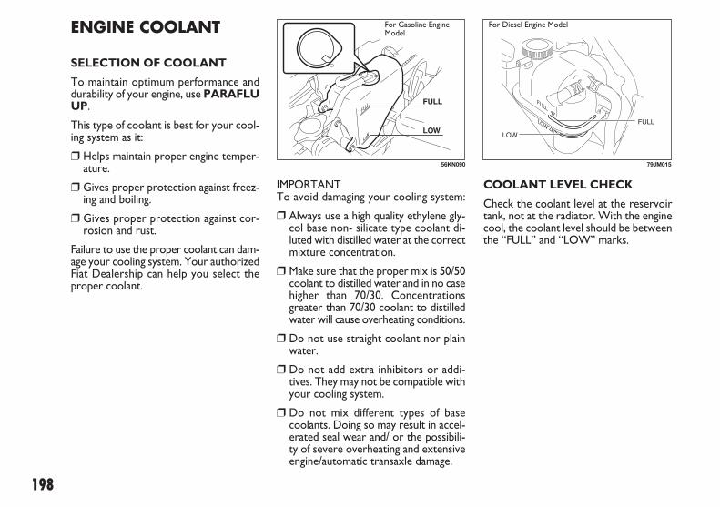
198
IMPORTANT To avoid damaging your cooling system:
❒ Always use a high quality ethylene gly-col base non- silicate type coolant di-luted with distilled water at the correctmixture concentration.
❒ Make sure that the proper mix is 50/50coolant to distilled water and in no casehigher than 70/30. Concentrationsgreater than 70/30 coolant to distilledwater will cause overheating conditions.
❒ Do not use straight coolant nor plainwater.
❒ Do not add extra inhibitors or addi-tives. They may not be compatible withyour cooling system.
❒ Do not mix different types of basecoolants. Doing so may result in accel-erated seal wear and/ or the possibili-ty of severe overheating and extensiveengine/automatic transaxle damage.
ENGINE COOLANT
SELECTION OF COOLANT
To maintain optimum performance anddurability of your engine, use PARAFLUUP.
This type of coolant is best for your cool-ing system as it:
❒ Helps maintain proper engine temper-ature.
❒ Gives proper protection against freez-ing and boiling.
❒ Gives proper protection against cor-rosion and rust.
Failure to use the proper coolant can dam-age your cooling system. Your authorizedFiat Dealership can help you select theproper coolant.
56KN090
For Gasoline EngineModel
COOLANT LEVEL CHECK
Check the coolant level at the reservoirtank, not at the radiator. With the enginecool, the coolant level should be betweenthe “FULL” and “LOW” marks.
LOW
FULLFULLFULL
79JM015
For Diesel Engine Model
183-230 SEDICI LUM FL GB 1E 19-06-2009 11:00 Pagina 198

199
ADDING COOLANT
Engine coolant is harmful orfatal if swallowed or inhaled.
Do not drink antifreeze or coolant so-lution. If swallowed, do not inducevomiting. Immediately contact a poi-son control center or a physician.Avoid inhaling mist or hot vapors; ifinhaled, remove to fresh air. Ifcoolant gets in eyes, flush eyes withwater and seek medical attention.Wash thoroughly after handling. So-lution can be poisonous to animals.Keep out of the reach of children andanimals.
WARNINGIMPORTANT
❒ The mixture you use should contain50% concentration of antifreeze.
❒ If the lowest ambient temperature inyour area is expected to be –35°C (–31°F) or below, use higher concen-trations up to 60% following the in-structions on the antifreeze container.
❒ When putting the cap on the reservoirtank, line up the arrow on the cap andthe arrow on the tank. Failure to followthis can result in coolant leakage.
If the coolant level is below the “LOW”mark, more coolant should be added.
When the engine is cool, remove the de-gassing tank cap by turning it anticlock-wise slowly to release any pressure. Andadd coolant until the degassing tank levelreaches the “FULL” mark. Never fill thedegassing tank above the “FULL” mark.
It is hazardous to remove thedegassing tank cap for Diesel
engine when the water temperatureis high, because scalding fluid andsteam may be blown out under pres-sure. Wait until the coolant temper-ature has lowered before removingthe cap.
WARNING
183-230 SEDICI LUM FL GB 1E 19-06-2009 11:00 Pagina 199
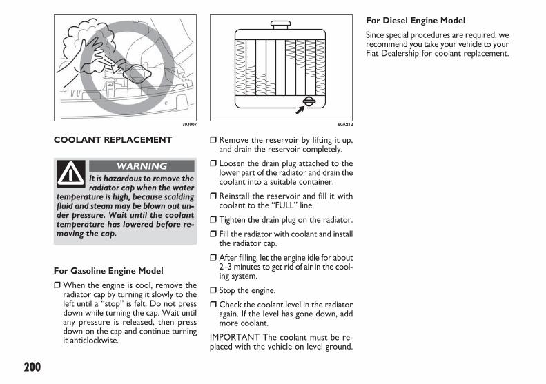
200
COOLANT REPLACEMENT
79J007
It is hazardous to remove theradiator cap when the water
temperature is high, because scaldingfluid and steam may be blown out un-der pressure. Wait until the coolanttemperature has lowered before re-moving the cap.
WARNING
For Gasoline Engine Model
❒ When the engine is cool, remove theradiator cap by turning it slowly to theleft until a “stop” is felt. Do not pressdown while turning the cap. Wait untilany pressure is released, then pressdown on the cap and continue turningit anticlockwise.
For Diesel Engine Model
Since special procedures are required, werecommend you take your vehicle to yourFiat Dealership for coolant replacement.
❒ Remove the reservoir by lifting it up,and drain the reservoir completely.
❒ Loosen the drain plug attached to thelower part of the radiator and drain thecoolant into a suitable container.
❒ Reinstall the reservoir and fill it withcoolant to the “FULL” line.
❒ Tighten the drain plug on the radiator.
❒ Fill the radiator with coolant and installthe radiator cap.
❒ After filling, let the engine idle for about2–3 minutes to get rid of air in the cool-ing system.
❒ Stop the engine.
❒ Check the coolant level in the radiatoragain. If the level has gone down, addmore coolant.
IMPORTANT The coolant must be re-placed with the vehicle on level ground.
60A212
183-230 SEDICI LUM FL GB 1E 19-06-2009 11:00 Pagina 200
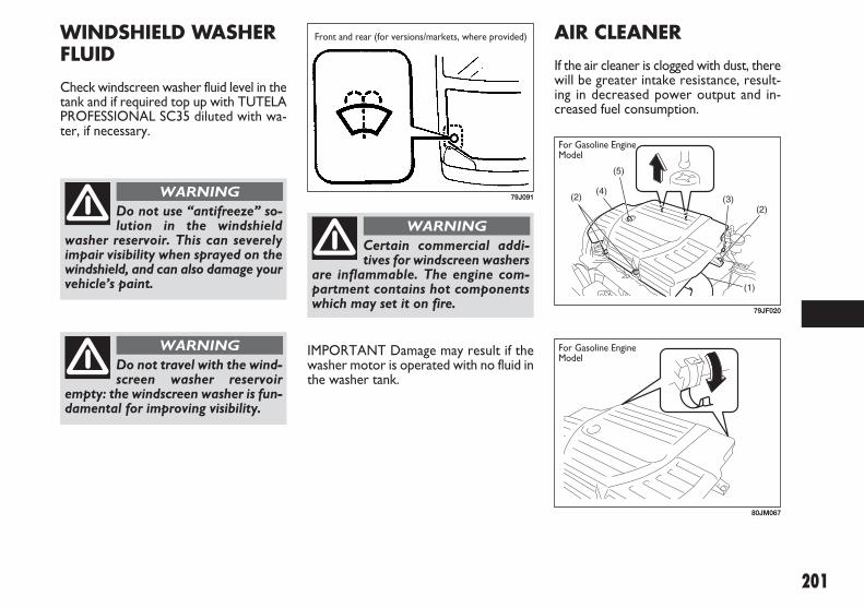
201
AIR CLEANER
If the air cleaner is clogged with dust, therewill be greater intake resistance, result-ing in decreased power output and in-creased fuel consumption.
IMPORTANT Damage may result if thewasher motor is operated with no fluid inthe washer tank.
79J091
Front and rear (for versions/markets, where provided)WINDSHIELD WASHERFLUID
Check windscreen washer fluid level in thetank and if required top up with TUTELAPROFESSIONAL SC35 diluted with wa-ter, if necessary.
Do not use “antifreeze” so-lution in the windshield
washer reservoir. This can severelyimpair visibility when sprayed on thewindshield, and can also damage yourvehicle’s paint.
WARNING
Certain commercial addi-tives for windscreen washers
are inflammable. The engine com-partment contains hot componentswhich may set it on fire.
WARNING
Do not travel with the wind-screen washer reservoir
empty: the windscreen washer is fun-damental for improving visibility.
WARNING
(4)
(5)
(1)
(2) (3)(2)
79JF020
80JM067
For Gasoline EngineModel
For Gasoline EngineModel
183-230 SEDICI LUM FL GB 1E 19-06-2009 11:00 Pagina 201

202
To remove the air cleaner element:
❒ Remove the air cleaner inlet hose (1).
❒ Remove the bolts (2), loosen the bolt(3) and lift the air cleaner case (4) di-rectly above.
IMPORTANT When lifting the air clean-er, make sure the air cleaner does not in-terfere the engine oil dipstick (5) to avoiddamage the dipstick.
❒ Unclamp the side clamps, and removethe element from the air cleaner case.If it appears to be dirty, replace it witha new one.
SPARK PLUGS (Gasoline engine)
For Nickel spark plugs (traditional type):
You should inspect spark plugs periodi-cally for carbon deposits. When carbonaccumulates on a spark plug, a strongspark may not be produced. Remove car-bon deposits with a wire or pin and adjustthe spark plug gap.
To access the spark plugs:
❒ Remove the air cleaner case. Refer to“Air Cleaner” in this section.
❒ If necessary, disconnect the coupler (1)while pushing the release lever.
❒ Remove the ignitor bolts.
❒ Pull the spark plug boots out.
NOTE When installation, make sure thewires, couplers, sealing rubber of air clean-er assy and washers, are correctly re-turned in place.
(1)
80JM125
60G102
Correct Wrong
79JM016
For Diesel Engine Model
183-230 SEDICI LUM FL GB 1E 19-06-2009 11:00 Pagina 202

203
Spark plug gap “a” K16HPR-U11SILFR6A111.0 – 1.1 mm (0.039 – 0.043 in.)
IMPORTANT When replacing sparkplugs, you should use the brand and typespecified for your vehicle. For the speci-fied plugs, refer to the “SPECIFICA-TIONS” section at the end of this book. Ifyou wish to use a brand of spark plug oth-er than the specified plugs, consult yourFiat Dealership.
54G106
IMPORTANT
❒ When installing the spark plugs, screwthem in with your fingers to avoid strip-ping the threads. Tighten with a torquewrench to 25 Nm (2.5 kgm, 18.0 lb-ft).Do not allow contaminants to enter theengine through the spark plug holeswhen the plugs are removed.
❒ Never use spark plugs with the wrongthread size.
IMPORTANT
❒ When disconnecting the spark plug ca-bles, pull on the boot, not on the ca-ble itself. Pulling on the cable can dam-age it.
❒ When servicing the Iridium/ Platinumspark plugs (slender center electrodetype plugs), do not touch the centerelectrode, as it is easy to damage.
60G160S
Loosen
Tighten
183-230 SEDICI LUM FL GB 1E 19-06-2009 11:00 Pagina 203

204
NOTE If your engine is equipped with thehightension cord type ignition wiring andyou experience some firing problem ofspark plugs, such as, hard engine- starting,misfire etc., the cause may be located notonly on spark plugs but also on deterio-rated ignition wirings (generally, used formore than 80,000 km or five years). Ifspark plug replacement does not solve theproblem, have the ignition wiring and oth-er ignition system inspected by your FiatDealership.
FUEL FILTER (Diesel engine)
The fuel filter works as a water sedimen-tor as well.
Drain water when the fuel filter warninglight comes on. To drain water:
❒ Place a pan or ample rag under the fu-el filter drain nozzle.
❒ Loosen the drain knob (1). The waterwill be drained.
❒ Tighten the drain knob when the waterchanges to the diesel fuel.
❒ Tighten the drain knob.
(1)
79J147
183-230 SEDICI LUM FL GB 1E 19-06-2009 11:00 Pagina 204

205
NOTE With disc brakes, the fluid level canbe expected to gradually fall as the brakepads wear.
BRAKES
BRAKE FLUID
Check the brake fluid level by looking atthe reservoir in the engine compartment.Check that the fluid level is between the“MAX” and “MIN” lines. If the brake flu-id level is near the “MIN” line, fill it up tothe “MAX” line with TUTELA TOP 4 SAEJ1704 o DOT4 brake fluid.
79J148
Failure to follow the guide-lines below can result in per-
sonal injury or serious damage to thebrake system.– If the brake fluid in the reservoirdrops below a certain level, the brakewarning light on the instrument pan-el will come on (the engine must berunning with the parking brake fullydisengaged). Should the light comeon, immediately ask your Fiat Deal-ership to inspect the brake system.– A rapid fluid loss indicates a leak inthe brake system which should be in-spected by your Fiat Dealership im-mediately.
WARNING – Brake fluid can harm youreyes and damage painted
surfaces. Use caution when refillingthe reservoir.– Do not use any fluid other than SAEJ1704 or DOT4 brake fluid. Do notuse reclaimed fluid or fluid that hasbeen stored in old or open contain-ers. It is essential that foreign parti-cles and other liquids are kept out ofthe brake fluid reservoir.
WARNING
Brake fluid is harmful or fa-tal if swallowed, and harm-
ful if it comes in contact with skin oreyes. If swallowed, do not inducevomiting. Immediately contact a poi-son control center or a physician. Ifbrake fluid gets in eyes, flush eyeswith water and seek medical atten-tion. Wash thoroughly after handling.Solution can be poisonous to animals.Keep out of the reach of children andanimals.
WARNING
183-230 SEDICI LUM FL GB 1E 19-06-2009 11:00 Pagina 205

206
With the engine running, measure the dis-tance between the brake pedal and floorcarpet when the pedal is depressed withapproximately 30 kg (66 lbs) of force. Theminimum distance required is as specified.Since your vehicle’s brake system is self-adjusting, there is no need for pedal ad-justment.
If the pedal to floor wall distance as mea-sured above is less than the minimum dis-tance required, have your vehicle in-spected by your Fiat Dealership.
NOTE When measuring the distance be-tween the brake pedal and floor wall, besure not to include the floor mat or rub-ber on the floor wall in your measure-ment.
BRAKE PEDAL
Check if the brake pedal stops at the reg-ular height without “spongy” feeling whenyou depress it. If not, have the brake sys-tem inspected by your Fiat Dealership. Ifyou doubt the brake pedal for the regu-lar height, check it as follows:
Pedal to wall minimum distance“a”: 40 mm (1.6 in.)
54G108 60G104S
If you experience any of thefollowing problems with
your vehicle’s brake system, have thevehicle inspected immediately byyour Fiat Dealership.– Poor braking performance– Uneven braking (Brakes not work-ing uniformly on all wheels.)– Excessive pedal travel– Brake dragging– Excessive noise– Pedal pulsation (Pedal pulsateswhen depressed.)
WARNING
183-230 SEDICI LUM FL GB 1E 19-06-2009 11:00 Pagina 206

207
STEERING
Steering wheel play “c”:0 – 30 mm (0.0 – 1.2 in.)
Check the play of the steering wheel bygently turning it from left to right and mea-suring the distance that it moves beforeyou feel slight resistance. The play shouldbe between the specified values.
Check that the steering wheel turns eas-ily and smoothly without rattling by turn-ing it all the way to the right and to the leftwhile driving very slowly in an open area.If the amount of free play is outside thespecification or you find anything else tobe wrong, an inspection must be per-formed by your Fiat Dealership.
PARKING BRAKE
Ratchet tooth specification “b”:4th – 9th Lever pull force (1): 200 N (20 kg, 44 lbs)
Check the parking brake for proper ad-justment by counting the number of clicksmade by the ratchet teeth as you slowlypull up on the parking brake lever to thepoint of full engagement. The parkingbrake lever should stop between the spec-ified ratchet teeth and the rear wheelsshould be securely locked. If the parkingbrake is not properly adjusted or thebrakes drag after the lever has been fullyreleased, have the parking brake inspect-ed and/ or adjusted by your Fiat Dealer-ship.
54G109
“c”
80JM008
183-230 SEDICI LUM FL GB 1E 19-06-2009 11:00 Pagina 207
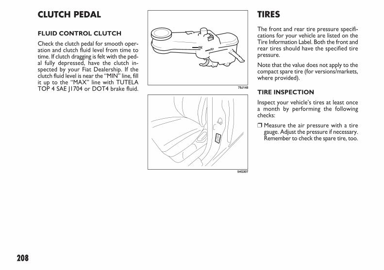
208
TIRES
The front and rear tire pressure specifi-cations for your vehicle are listed on theTire Information Label. Both the front andrear tires should have the specified tirepressure.
Note that the value does not apply to thecompact spare tire (for versions/markets,where provided).
TIRE INSPECTION
Inspect your vehicle’s tires at least oncea month by performing the followingchecks:
❒ Measure the air pressure with a tiregauge. Adjust the pressure if necessary.Remember to check the spare tire, too.
CLUTCH PEDAL
FLUID CONTROL CLUTCH
Check the clutch pedal for smooth oper-ation and clutch fluid level from time totime. If clutch dragging is felt with the ped-al fully depressed, have the clutch in-spected by your Fiat Dealership. If theclutch fluid level is near the “MIN” line, fillit up to the “MAX” line with TUTELATOP 4 SAE J1704 or DOT4 brake fluid. 79J148
54G307
183-230 SEDICI LUM FL GB 1E 19-06-2009 11:00 Pagina 208

209
1. Tread wear indicator2. Indicator location mark
❒ Check that the depth of the treadgroove is more than 1.6 mm (0.06 in.).To help you check this, the tires havemolded- in tread wear indicators in thegrooves. When the indicators appearon the tread surface, the remainingdepth of the tread is 1.6 mm (0.06 in.)or less and the tire should be replaced.
❒ Check for abnormal wear, cracks anddamage. Any tires with cracks or oth-er damage should be replaced. If anytires show abnormal wear, have theminspected by your Fiat Dealership.
❒ Check for loose wheel bolts.
❒ Check that there are no nails, stonesor other objects sticking into the tires.
54G136
– Air pressures should bechecked when the tires are
cold or you may get inaccurate read-ings.– Check the inflation pressure fromtime to time while inflating the tiregradually, until the specified pressureis obtained.– Never underinflate or overinflatethe tires.Underinflation can cause unusualhandling characteristics or can causethe rim to slip on the tire bead, re-sulting in an accident or damage tothe tire or rim.Overinflation can cause the tire toburst, resulting in personal injury.Overinflation can also cause unusu-al handling characteristics which mayresult in an accident.
WARNINGHitting curbs and runningover rocks can damage tires
and affect wheel alignment. Be sureto have tires and wheel alignmentchecked periodically by your FiatDealership.
WARNING
183-230 SEDICI LUM FL GB 1E 19-06-2009 11:00 Pagina 209

210
IMPORTANT Replacing the original tireswith tires of a different size may result infalse speedometer or odometer readings.Check with your Fiat Dealership beforepurchasing replacement tires that differ insize from the original tires.
IMPORTANT For 4-wheel drive (4WD)models, replacing a tire with one of a dif-ferent size, or using different brandsamong the four tires can result in dam-age to the drive train.
TIRE ROTATION
To avoid uneven wear of your tires and toprolong their life, rotate the tires as illus-trated. Tires should be rotated every10,000 km (6,000 miles). After rotation,adjust front and rear tire pressures to thespecification listed on your vehicle’s TireInformation Label.
– Your Fiat is equipped withtires which are all the same
type and size. This is important to en-sure proper steering and handling ofthe vehicle. Never mix tires of differ-ent size or type on the four wheels ofyour vehicle. The size and type oftires used should be only those ap-proved by Fiat as standard or op-tional equipment for your vehicle.– Replacing the wheels and tiresequipped on your vehicle with certaincombinations of aftermarket wheelsand tires can significantly change thesteering and handling characteristicsof your vehicle.– Therefore, use only those wheel andtire combinations approved by Fiat asstandard or optional equipment foryour vehicle.
WARNING
54G114
4-tire rotation
183-230 SEDICI LUM FL GB 1E 19-06-2009 11:00 Pagina 210

211
COMPACT SPARE TIRE (for versions/markets, where provided)
1. Wear indicator2. Indicator location mark
Your vehicle comes equipped with thecompact spare tire. The compact spare isdesigned to save space in your storage area,and its lighter weight makes it easier to in-stall if a flat tire occurs. It is only intendedfor temporary emergency use, until theconventional tire can be repaired or re-placed. The inflation pressure of the com-pact spare tire should be checked at leastmonthly. Use a quality pocket- type infla-tion pressure gauge and set at 4.2 bar (60psi). At the same time, check that the tireis stored securely. If it is not, tighten it.
Note that two or more compact sparetires should not be used on one vehicle si-multaneously.
54G115
The compact spare tire andwheel are intended for tem-
porary emergency use only. Continu-ous use of this spare can result in tirefailure and loss of control. Always ob-serve these precautions when usingthis spare:– Your vehicle will handle differentlywith this temporary spare.– Do not exceed 80 km/h (50 mph)speed.– Replace this spare with a standardtire and wheel as soon as possible.– Use of this spare will reduce groundclearance.o Recommended air pressure for thisspare is 4.2 bar (420 kPa, 60 psi).– Do not use tire chains on the com-pact spare. If you must use tirechains, rearrange the wheels so stan-dard tires and wheels are fitted to thefront axle.
WARNING– The compact spare tire hasa much shorter tread life
than the conventional tires on yourvehicle. Replace the tire as soon asthe tread wear indicator appears.– When replacing the compact sparetire, use a replacement tire with theexact same size and construction.
WARNING
183-230 SEDICI LUM FL GB 1E 19-06-2009 11:00 Pagina 211

212
❒ Insert the new wheel to the wheelhanger. Install the wheel bolts to boltholes other than the position of wheelhanger with their cone shaped end fac-ing the wheel. Tighten each bolt snug-ly by hand until the wheel is securelyseated on the hub.
❒ Remove the wheel hanger and install awheel bolt.
CHANGING WHEELS
To change a wheel, use the following pro-cedure:❒ Remove the jack, tools and spare wheel
from the vehicle.❒ Loosen, but do not remove the wheel
bolts.❒ Jack up the vehicle (follow the jacking
instructions in the “EMERGENCY SER-VICE” section).
❒ Remove the wheel bolts and wheel.❒ Before installing the new wheel, clean
any mud or dirt off from the surface ofthe wheel and hub with a clean cloth.Clean the hub carefully; it may be hotfrom driving.
❒ Tighten the wheel hanger (1) in one ofthe bolt holes on the wheel hub.
IMPORTANT Do not tighten the wheelhanger too hard since the wheel hangercan be damaged.
79J196
– Be sure to shift into “P”(Park) for an automatic
transaxle vehicle, or into “R” (Reverse)for a manual transaxle vehicle whenyou jack up the vehicle.– Never jack up the vehicle with thetransaxle in “N” (Neutral). Other-wise, unstable jack may cause an ac-cident.
WARNING
Tightening torque for wheel bolt85 Nm (8.5 kgm, 61.5 lb-ft)
❒ Lower the jack and fully tighten thebolts in a crisscross fashion with awrench as shown in the illustration.
81A057
(1)
79JM017
Use genuine wheel bolts andtighten them to the specified
torque as soon as possible after chang-ing wheels. Incorrect wheel bolts or im-properly tightened wheel bolts maycome loose or fall off, which can resultin an accident. If you do not have atorque wrench, have the wheel bolttorque checked by an authorized FiatDealership.
WARNING
183-230 SEDICI LUM FL GB 1E 19-06-2009 11:00 Pagina 212

213
BATTERY
– Batteries produce flam-mable hydrogen gas. Keep
flames and sparks away from the bat-tery or an explosion may occur. Nev-er smoke when working in the vicini-ty of the battery.– When checking or servicing the bat-tery, disconnect the negative cable.Be careful not to cause a short circuitby allowing metal objects to contactthe battery posts and the vehicle atthe same time.– To avoid harm to yourself or dam-age to your vehicle or battery, followthe jump starting instructions in the“EMERGENCY SERVICE” section ofthis manual if it is necessary to jumpstart your vehicle.
WARNING
FULL WHEEL COVER (for versions/markets, where provided)
1. or 2. Flat end tool
Your vehicle includes two tools, a wheelbrace and a jack crank, one of which hasa flat end.
Use the tool with the flat end to removethe full wheel cap, as shown above.
When installing the cover, make sure thatit is positioned so that it does not coveror foul the air valve.
60G309
54G117
Your vehicle is equipped with a batterythat requires infrequent maintenance. Youwill never have to add water. You should,however, periodically check the battery,battery terminals and battery hold- downbracket for corrosion. Remove corrosionusing a stiff brush and ammonia mixed withwater, or baking soda mixed with water.After removing corrosion, rinse with cleanwater.
The test indicator on the top of the bat-tery provides information on the condi-tion of the battery.
If your vehicle is not going to be driven fora month or longer, disconnect the cablefrom the negative terminal of the batteryto help prevent discharge.
60A269
183-230 SEDICI LUM FL GB 1E 19-06-2009 11:00 Pagina 213

214
Batteries contain toxic sub-stances including sulfuric
acid and lead. They could have po-tential negative consequences for theenvironment and human health. Usedbattery must be disposed or recycledaccording to the local law and mustnot be discarded with ordinary house-hold trash. Make sure not to tip overthe battery when you remove it fromthe vehicle. Otherwise, sulfuric acidcould run out and you might get in-jury.
WARNING
(1)
(2)
(3)
(4)
51KM039
(1)
(2)
(4)
(3)
51KM041
Pb
(5)
(6)
51KM042
REPLACEMENT OF THE BATTERY
To remove the battery
❒ Disconnect the negative cable (1).
❒ Disconnect the positive cable (2).
❒ Remove the retainer bolt (3) and re-move the retainer (4).
❒ Remove the battery.
To install the battery:
❒ Install the battery in the reverse orderof removal.
❒ Tighten the retainer bolt and batterycables securely.
5. Crossed-out wheeled bin symbol6. Chemical symbol of “Pb”
The crossed-out wheeled bin symbol (5)located on the battery label indicates thatused battery should be collected sepa-rately from ordinary household trash. Thechemical symbol of “Pb” (6) indicates thebattery contains more than 0.004% lead.
By ensuring the used battery is disposedor recycled correctly, you will help pre-vent potential negative consequences forthe environment and human health, whichcould otherwise be caused by inappropri-ate trash handling of the battery. The re-cycling of materials will help to conservenatural resources. For more detailed in-formation about disposing or recycling ofthe used battery, consult your Fiat Deal-ership.
NOTE When the battery is disconnect-ed, some of the vehicle’s function will beinitialized and/or deactivated.These function are required to reset af-ter the battery is reconnected.
For Gasoline Engine Model For Diesel Engine Model
183-230 SEDICI LUM FL GB 1E 19-06-2009 11:00 Pagina 214

215
FUSES IN THE ENGINECOMPARTMENT
The main fuse, primary fuses and some ofthe individual fuses are located in the en-gine compartment. If the main fuse blows,no electrical component will function. Ifa primary fuse blows, no electrical com-ponent in the corresponding load groupwill function. When replacing the mainfuse, a primary fuse or an individual fuse,use a genuine Fiat replacement.
60G111
OK
BLOWN
If the main fuse or a primaryfuse blows, be sure to have
your vehicle inspected by an autho-rized Fiat Dealership. Always use agenuine Fiat replacement. Never usea substitute such as a wire even for atemporary repair, or extensive elec-trical damage and a fire can result.
WARNING
FUSES
Your vehicle has three types of fuses, asdescribed below:
Main fuse
The main fuse takes current directly fromthe battery.
Primary fuses
These fuses are between the main fuse andindividual fuses, and are for electrical loadgroups.
Individual fuses
These fuses are for individual electrical cir-cuits.
To remove a fuse, use the fuse puller pro-vided in the fuse box. The amperage ofeach fuse is shown in the back of the fusebox cover.
63J095
NOTE Make sure that the fuse box alwayscarries spare fuses.
183-230 SEDICI LUM FL GB 1E 19-06-2009 11:00 Pagina 215

216
(1)
(2)
(3)
(4)
(5)
62J085
(28)
(27)(26)(25)
(6) (7) (9) (11)
(12) (13) (14) (15) (16) (17) (18) (19)
(24)
(8) (10)
(22)(21)
(23)
(20)
79J092
80A
50A
50A
80A
80A
15A
15A
20A
60A
40A
30A
30A
30A
50A
30A
All electric load
Power window, Ignition Wiper, Starter
Tail light, Rear defogger, Door lock, Hazard/Horn, Dome
Heater, Air compressor, Power steering
Radiator fan, Front fog light, Head light
Head light (Right) fuse
Head light (Left) fuse
Front fog light fuse
Power steering control module fuse
ABS motor fuse
Radiator fan fuse
ABS solenoid fuse
Starting motor fuse
Ignition switch fuse
Blower fan fuse
FUSES IN THE ENGINE COMPARTMENT
For Gasoline Engine Model
Main fuse / Primary fuse
(1)
(2)
(3)
(4)
(5)
(6)
(7)
(8)
(9)
(10)
(11)
(12)
(13)
(14)
(15)
183-230 SEDICI LUM FL GB 1E 19-06-2009 11:00 Pagina 216

217
20A
15A
15A
15A
–
–
–
–
–
–
–
–
–
–
Air compressor fuse
Throttle motor fuse
Automatic transaxle fuse (for versions/markets, where provided)
Fuel injection fuse
Automatic transaxle relay (for versions/markets, where provided)
Air compressor relay
Fuel pump relay
Condenser fan relay
Front fog light relay
Throttle motor relay
FI MAIN
Starting motor relay
Radiator fan relay
Shift lock relay
Main fuse / Primary fuse
(16)
(17)
(18)
(19)
(20)
(21)
(22)
(23)
(24)
(25)
(26)
(27)
(28)
(29)
183-230 SEDICI LUM FL GB 1E 19-06-2009 11:00 Pagina 217

218
(6) (7)
(4) (5)(2)(1) (3)
79J172
(33)
(30)(29)(28)
(8) (9) (14)
(16)(15) (17) (18) (19) (20) (21) (22)
(27)
(10) (11) (13)(12)
(25)(24)
(26)
(23)
(32)
(31)
79J149
80A
30A
140A
50A
30A
30A
30A
15A
15A
20A
50A
60A
40A
30A
30A
30A
50A
30A
(34) (35)
(36)
(37)
(38)
79J173
Glow
Fuel heater
All electric load
Light
Sub heater
Sub heater
Sub heater
Head light (Right) fuse
Head light (Left) fuse
Front fog light fuse
Ignition
Power steering control module fuse
ABS motor fuse
Radiator fan fuse
ABS solenoid fuse
Starting motor fuse
Ignition
Blower fan fuse
For Diesel Engine Model
Main fuse / Primary fuse
(1)
(2)
(3)
(4)
(5)
(6)
(7)
(8)
(9)
(10)
(11)
(12)
(13)
(14)
(15)
(16)
(17)
(18)
183-230 SEDICI LUM FL GB 1E 19-06-2009 11:00 Pagina 218

219
10A
20A
30A
20A
–
–
–
–
–
–
–
–
–
–
–
–
–
10A
10A
15A
Main fuse / Primary fuse
(19)
(20)
(21)
(22)
(23)
(24)
(25)
(26)
(27)
(28)
(29)
(30)
(31)
(32)
(33)
(34)
(35)
(36)
(37)
(38)
Air compressor fuse
Fuel pump fuse
Condenser fan fuse
Fuel injection fuse
Sub heater relay 3
Air compressor relay
Fuel pump relay
Condenser fan relay
Front fog light relay
Sub heater relay 2
Sub heater relay
Starting motor relay
Radiator fan relay
Radiator fan relay
Radiator fan relay
Fuel heater
Fuel injection main
EPI
Fuel injection
INJ DVR
183-230 SEDICI LUM FL GB 1E 19-06-2009 11:00 Pagina 219

220
15A15A10A10A15A15A30A30A10A15A10A10A10A20A15A10A15A10A10A15A30A15A10A
79J093
79J011
Rear wiperIgnition coilBack-up lightMeterAccessoryAccessory 2Power windowWiperIG1 SIGAir bagAnti-lock brake systemTail lightStop lightDoor lock4WD lightST SIGSeat heaterIG 2 SIGRear fog lightDomeRear defoggerHorn / HazardFiat CODE (Immobilizer)
FUSES UNDER THE DASH BOARD
Main fuse / Primary fuse
(1)(2)(3)(4)(5)(6)(7)(8)(9)(10)(11)(12)(13)(14)(15)(16)(17)(18)(19)(20)(21)(22)(23)
183-230 SEDICI LUM FL GB 1E 19-06-2009 11:00 Pagina 220

221
BULB REPLACEMENT
The fuses are also located under the dri-ver’s side of the dashboard. Remove thefuse box cover by pulling it off. The am-perage of each fuse is shown on the topof the fuse box cover.
Always be sure to replace ablown fuse with a fuse of the
correct amperage. Never use a sub-stitute such as aluminum foil or wireto replace a blown fuse. If you re-place a fuse and the new one blowsin a short period of time, you mayhave a major electrical problem.Have your vehicle inspected imme-diately by your Fiat Dealership.
WARNING
65D046
OK BLOWN
– Light bulbs can be hotenough to burn your finger
right after being turned off. This istrue especially for halogen headlightbulbs. Replace the bulbs after theybecome cool enough.– The headlight bulbs are filled withpressurized halogen gas. They canburst and injure you if they are hit ordropped. Handle them carefully.
WARNING
IMPORTANT The oils from your skin maycause a halogen bulb to overheat and burstwhen the lights are on. Grasp a new bulbwith a clean cloth.
IMPORTANT Frequent replacement of abulb indicates the need for an inspectionof the electrical system. This should becarried out by your Fiat Dealership.
CENTER INTERIOR LIGHT (for versions/markets, where provided)
Pull down the lens by using a plane screwdriver covered with a soft cloth as shown.To install it, simply push it back in.
The bulb can be removed by simply pullingit out. When replacing the bulb, make surethat the contact springs are holding thebulb securely.
60G115
183-230 SEDICI LUM FL GB 1E 19-06-2009 11:00 Pagina 221

222
HEADLIGHT
Open the engine food. Disconnect thecoupler (1). Remove the sealing rubber (2).Push the retaining spring (3) forward andunhook it. Then remove the bulb. Installa new bulb in the reverse order of remo-val.
(2)
(1)
(3)
80JM069
(3)
80JM113
(2)
(4)
(3)
(1)
79JM026
NOTE You can see the position of retai-ning spring (3) from the hole of headlight.
For Diesel Engine Model
To approach the air cleaner side head li-ght:
❒ Loosen the bolt (1).
❒ Pull up the air cleaner (2) and pull outthe air cleaner hose (4) from the aircleaner (2).
❒ Loosen the bolts (3) and remove the aircleaner hose (4).
183-230 SEDICI LUM FL GB 1E 19-06-2009 11:00 Pagina 222

223
SIDE TURN SIGNAL LIGHT
As the bulb is built-in type, the light as-sembly must be replaced. Remove the lightassembly by sliding the light housing left-ward with your finger.
64J195
OTHER GENERAL LIGHTS
Bulb holder
1. Removal2. Installation
To remove a bulb holder from a lighthousing, turn the holder counterclockwiseand pull it out. To install the holder, pushthe holder in and turn it clockwise.
(1)
(1)
(2)
(2)
54G123
(1)
(2)
(3)
(4)
54G124
Bulb
3. Removal4. Installation
There are two types of bulb, “Full glasstype” (1) and “Glass/ metal type” (2).
To remove and install a full glass type bulb(1), simply pull out or push in the bulb.
To remove a glass metal type bulb (2)from a bulb holder, push in the bulb andturn it counterclockwise. To install a newbulb, push it in and turn it clockwise.
You can access the individual bulb or bulbholders as follows.
183-230 SEDICI LUM FL GB 1E 19-06-2009 11:00 Pagina 223

224
(1) (2)
80JM123
(1)
(2)
80JM114 80JM071
(3)
79JM025
Front turn signal light (1)Front position light (2)
Front fog light(for versions/markets, where provided)
NOTE To replace the bulb easily, turn thesteering wheel to the opposite side of thereplacing fog light.
❒ Insert a flat blade screwdriver into thehole (2) and remove the clips (1) by twi-st the driver as shown in the illustration.
❒ Remove the bolts (3).
❒ Open the fender cover. Disconnect thecoupler with pushing the lock release.
❒ Turn the bulb holder counterclockwi-se and remove it.
183-230 SEDICI LUM FL GB 1E 19-06-2009 11:00 Pagina 224
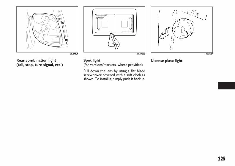
225
80JM131 80JM068
Rear combination light (tail, stop, turn signal, etc.)
Spot light (for versions/markets, where provided)
Pull down the lens by using a flat bladescrewdriver covered with a soft cloth asshown. To install it, simply push it back in.
75F087
License plate light
183-230 SEDICI LUM FL GB 1E 19-06-2009 11:00 Pagina 225

226
(2)
63J127
(1)
63J106
(3)(3) (4)
80JM076
High-mount stop light (for versions/markets, where provided)
To remove a high-mounted stop lighthousing the following procedure:
❒ Open the tailgate, and remove thenuts (1) as shown in the illustration.
❒ Close the tailgate. Remove a high-mounted stop light housing (2) fromthe tailgate.
❒ Pushing the unguiform prongs (3)toward inside and remove the bulbholder (4).
❒ Replace the bulbs.
❒ To install a high-mounted stop lighthousing in the reverse order of re-moval.
79J015
Luggage compartment light
183-230 SEDICI LUM FL GB 1E 19-06-2009 11:00 Pagina 226

227
❒ Squeeze lock (1) towards wiper arm (2)and remove the wiper frame from thearm as shown.
❒ Unlock the lock end of the wiperblade and slide the blade out asshown.
54G130
WIPER BLADES
If the wiper blades become brittle or dam-aged, or make streaks when wiping, re-place the wiper blades.
To install new wiper blades, follow theprocedures below.
IMPORTANT To avoid scratching orbreaking the window, do not let the wiperarm strike the window while replacing thewiper blade.
NOTE Some wiper blades may be differ-ent from the ones described here de-pending on vehicle specifications. If so,consult your Fiat Dealership for properreplacement method.
FOR WINDSCREEN WIPERS
❒ Hold the wiper arm away from the win-dow.
NOTE When raising both of the frontwiper arms, pull the driver’s side wiperarm up first. When returning the wiperarms, lower the passenger’s side wiperarm first. Otherwise, the wiper arms mayinterfere with each other.
54G129
Driving with worn wiperblades is a serious hazard,
because visibility is reduced in badweather.
WARNING70G119
183-230 SEDICI LUM FL GB 1E 19-06-2009 11:00 Pagina 227

228
60A260
54G132
54G133 65D151
54G134
Type A (Removal / Installation)
1. Locked end
Type B (Removal / Installation)
1. Locked end
Type C
NOTE For Type C, do not flex the wiperblade frame end more than necessary. Ifyou do, it can break off.
183-230 SEDICI LUM FL GB 1E 19-06-2009 11:00 Pagina 228

229
54G135 65D151
80G146
1. Retainer
❒ If the new blade is provided without thetwo metal retainers, move them fromthe old blade to the new one.
❒ Install the new blade in the reverse or-der of removal, with the locked end po-sitioned toward the wiper arm (exceptType C).
IMPORTANT Make sure the blade is pro-perly retained by all the hooks. Lock theblade end into place.
❒ Reinstall wiper frame to arm, making su-re that the lock lever is snapped secu-rely into the arm.
FOR REAR WIPERS
❒ Hold the wiper arm away from the win-dow.
❒ Remove the wiper frame from the armas shown.
❒ Slide the blade out as shown.
NOTE Do not flex the wiper blade frameend more than necessary. If you do, it canbreak off.
183-230 SEDICI LUM FL GB 1E 19-06-2009 11:00 Pagina 229

230
1. Retainer
❒ If the new blade is provided without thetwo metal retainers, move them fromthe old blade to the new one.
❒ Install the new blade in the reverse or-der of removal.
IMPORTANT Make sure the blade isproperly retained by all the hooks.
❒ Reinstall wiper frame to arm in the re-verse order of removal.
AIR CONDITIONINGSYSTEM
If you do not use the air conditioner fora long period, such as during winter, it maynot give the best performance when youstart using it again. To help maintain op-timum performance and durability of yourair conditioner, it needs to be run peri-odically.
Operate the air conditioner at least oncea month for one minute with the engineidling. This circulates the refrigerant andoil and helps protect the internal compo-nents.
54G135
183-230 SEDICI LUM FL GB 1E 19-06-2009 11:00 Pagina 230

231
EEMMEERRGGEENNCCYY SSEERRVVIICCEE
60G411
JACKING INSTRUCTIONS................................................ 232
JUMP STARTING INSTRUCTIONS ................................. 233
TOWING................................................................................ 235
IF THE STARTER DOES NOT OPERATE ...................... 236
IF THE ENGINE IS FLOODED .......................................... 236
IF THE ENGINE OVERHEATS........................................... 236
IF YOU CAN NOT SHIFT AUTOMATIC TRANSAXLEGEARSHIFT LEVER OUT OF “P” (PARK) ...................... 238
9
231-238 SEDICI LUM FL GB 1E 19-06-2009 11:06 Pagina 231

232
❒ Place the spare wheel near the wheelbeing lifted as shown in the illustrationin case that the jack is slipped.
❒ Position the jack vertically and raise thejack by turning the jack handle clock-wise until the jack head recess fits therod of the body.
❒ Continue to raise the jack slowly andsmoothly until the tire clears theground. Do not raise the vehicle morethan necessary.
JACKINGINSTRUCTIONS
❒ Place the vehicle on level, hard ground.
❒ Set the parking brake firmly and shift in-to “P” (Park) if your vehicle has an au-tomatic transaxle, or shift into “R” (Re-verse) if your vehicle has a manualtransaxle.
79JM014
75F062
– Be sure to shift into “P”(Park) in automatic transaxle,
or shift into “R” (Reverse) in manualtransaxle when you jack up the vehicle.– Never jack up the vehicle with thetransaxle in “N” (Neutral). Other-wise, unstable jack may cause an ac-cident.
WARNING
❒ Turn on the hazard warning flasher ifyour vehicle is near traffic.
❒ Block the front and rear of the wheeldiagonally opposite of the wheel beinglifted.
54G253
231-238 SEDICI LUM FL GB 1E 19-06-2009 11:06 Pagina 232

233
JUMP STARTINGINSTRUCTIONS– Use the jack only to change
wheels on level, hard ground.– Never jack up the vehicle on an in-clined surface.– Never raise the vehicle with the jackin a location other than between theframe bosses near the wheel to bechanged.– Make sure that the jack is raised atleast 51 mm (2 inches) before it con-tacts the flange. Use of the jack whenit is within 51 mm (2 inches) of beingfully collapsed may result in failure ofthe jack.– Never get under the vehicle when itis supported by the jack.– Never run the engine when the ve-hicle is supported by the jack andnever allow passengers to remain inthe vehicle.
WARNING
79J017
79J018
Front wheel
Rear wheel
– Never attempt to jumpstart your vehicle if the bat-
tery appears to be frozen. Batteriesin this condition may explode or rup-ture if jump starting is attempted.– When making jump lead connec-tions, be certain that your hands andthe jump leads remain clear from pul-leys, belts, or fans.– Batteries produce flammable hy-drogen gas. Keep flames and sparksaway from the battery or an explo-sion may occur. Never smoke whenworking in the vicinity of the battery.– If the booster battery you use forjump starting is installed in anothervehicle, make sure the two vehiclesare not touching each other.– If your battery discharges repeat-edly, for no apparent reason, haveyour vehicle inspected by an autho-rized Fiat Dealership.
WARNING
231-238 SEDICI LUM FL GB 1E 19-06-2009 11:06 Pagina 233

234
❒ Turn off all vehicle accessories, exceptthose necessary for safety reasons (forexample, headlights or hazard lights).
❒ Make jump lead connections as follows:
– Connect one end of the first jumplead to the positive (+) terminal ofthe flat battery (1).
– Connect the other end to the posi-tive (+) terminal of the booster bat-tery (2).
– Connect one end of the second jumplead to the negative (–) terminal ofthe booster battery (2).
– Make the final connection to an un-painted, heavy metal part (i. e. enginehook (3)) of the engine of the vehi-cle with the flat battery (1).
❒ If the booster battery you are using isfitted to another vehicle, start the en-gine of the vehicle with the booster bat-tery. Run the engine at moderatespeed.
❒ Start the engine of the vehicle with theflat battery.
❒ Remove the jump leads in the exact re-verse order in which you connectedthem.
IMPORTANT Your vehicle should not bestarted by pushing or towing. This start-ing method could result in permanentdamage to the catalytic converter. Usejump leads to start a vehicle with a weakor flat battery.
WHEN JUMP STARTING YOURVEHICLE, USE THEFOLLOWING PROCEDURE
❒ Use only a 12 volt battery to jump startyour vehicle. Position the good 12 Vbattery close to your vehicle so that thejump leads will reach both batteries.When using a battery installed on an-other vehicle, DO NOT LET THE VE-HICLES TOUCH. Set the parkingbrakes fully on both vehicles.
– To avoid harm to yourselfor damage to your vehicle or
battery, follow the jump starting in-structions below precisely and in order.If you are in doubt, call for qualifiedroad service.
WARNING
(1)
(3)
(2)
54G079
Never connect the jump leaddirectly to the negative (–)
terminal of the discharged battery, oran explosion may occur.
WARNING
231-238 SEDICI LUM FL GB 1E 19-06-2009 11:06 Pagina 234

235
2-WHEEL DRIVE (2WD)MANUAL TRANSAXLE
Manual transaxle vehicles may be towedusing either of the following methods.❒ From the front, with the front wheels
lifted and the rear wheels on theground. Before towing, make sure thatthe parking brake is released.
❒ From the rear, with the rear wheels lift-ed and the front wheels on the ground,provided the steering and drivetrain arein operational condition. Before tow-ing, make sure that transaxle is in neu-tral, the steering wheel is unlocked (theignition key should be in the “ACC” po-sition), and the steering wheel is se-cured with a clamping device designedfor towing service.
IMPORTANT The steering column is notstrong enough to withstand shocks trans-mitted from the front wheels during tow-ing. Always unlock the steering wheel be-fore towing.
TOWING
If you need to have your vehicle towed,contact a professional service. Your deal-er can provide you with detailed towinginstructions.
IMPORTANT To help avoid damage toyour vehicle during towing, proper equip-ment and towing procedures must beused.
2- WHEEL DRIVE (2WD)AUTOMATIC TRANSAXLE
Automatic transaxle vehicles may betowed using either of the following meth-ods.
❒ From the front, with the front wheelslifted and the rear wheels on theground. Before towing, make sure thatthe parking brake is released.
❒ From the rear, with the rear wheels lift-ed and a dolly under the front wheels.
IMPORTANT Towing your vehicle withthe front wheels on the ground can resultin damage to the automatic transaxle.
4-WHEEL DRIVE (4WD)
Your vehicle should be towed under oneof the following conditions:❒ With all four wheels on a flat-bed truck.❒ With the front or rear wheels lifted and
a dolly under the other wheels.❒ If you can shift the 2WD/4WD switch
to the “2WD” mode, and if the steer-ing and drive train are in good condi-tion and the engine can be started, thevehicle may also be towed according tothe instructions in the “Towing YourVehicle (recreational towing)” section.
IMPORTANT Towing your vehicle withfront and/or rear wheels on the groundcan result in damage to the automatictransaxle and/or the 4WD drive system.
231-238 SEDICI LUM FL GB 1E 19-06-2009 11:06 Pagina 235

236
IF THE ENGINEOVERHEATS
The engine could overheat temporarilyunder severe driving conditions. If the en-gine coolant temperature gauge indicatesoverheating during driving:
❒ Turn off the air conditioner, if equipped.
❒ Take the vehicle to a safe place andpark.
❒ Let the engine run at the normal idlespeed for a few minutes until the indi-cator is within the normal, acceptabletemperature range between “H” and“C”.
IF THE ENGINE ISFLOODED
If the engine is flooded with gasoline, itmay be hard to start. If this happens, pressthe accelerator pedal all the way to thefloor and hold it there while cranking theengine. (Do not operate the starter mo-tor for more than 15 seconds).
If you see or hear escapingsteam, stop the vehicle in a
safe place and immediately turn offthe engine to let it cool. Do not openthe hood when steam is present.When the steam can no longer beseen or heard, open the hood to seeif the coolant is still boiling. If it is, youmust wait until it stops boiling beforeyou proceed.
WARNING
IF THE STARTER DOESNOT OPERATE
❒ Try turning the ignition switch to the“START” position with the headlightsturned on to determine the batterycondition. If the headlights go exces-sively dim or go off, it usually meansthat either the battery is flat or the bat-tery terminal contact is poor. Rechargethe battery or correct battery terminalcontact as necessary.
❒ If the headlights remain bright, checkthe fuses. If the reason for failure of thestarter is not obvious, there may be amajor electrical problem. Have the ve-hicle inspected by your authorized Fiat Dealership.
231-238 SEDICI LUM FL GB 1E 19-06-2009 11:06 Pagina 236

237
❒ If you do not find a leak, carefully addcoolant to the reservoir and then theradiator, if necessary. (Refer to “EngineCoolant” in the “INSPECTION ANDMAINTENANCE” section.)
If the temperature indication does notcome down to within the normal, accept-able range:
❒ Turn off the engine and check that thewater pump belt and pulleys are notdamaged or slipping. If any abnormali-ty is found, correct it.
❒ Check the coolant level in the reser-voir. If it is found to be lower than the“LOW” line, look for leaks at the ra-diator, water pump, and radiator andheater hoses. If you locate any leaksthat may have caused the overheating,do not run the engine until these prob-lems have been corrected.
79J007
– It is hazardous to removethe radiator cap when the
water temperature is high, becausescalding fluid and steam may beblown out under pressure. The capshould only be taken off when thecoolant temperature has lowered.– To help prevent personal injury,keep hands, tools and clothing awayfrom the engine cooling fan and air-conditioner fan (if equipped). Theseelectric fans can automatically turnon without warning.
WARNING
231-238 SEDICI LUM FL GB 1E 19-06-2009 11:06 Pagina 237

238
(1)
68KM037
(1)
68KM038
IF YOU CANNOT SHIFT AUTOMATICTRANSAXLEGEARSHIFT LEVER OUT OF “P” (PARK)
Left Hand Drive Vehicle
Vehicles with an automatic transaxle havean electrically operated park- lock feature.If the vehicle’s battery is discharged, orthere is some other electrical failure, theautomatic transaxle cannot be shifted outof Park in the normal way. Jump startingmay correct the condition. If not, followthe procedure described below. This pro-cedure will permit shifting the transaxleout of Park.
❒ Be sure the parking brake is firmly ap-plied.
❒ If the engine is running, stop the engine.
❒ Make sure the key is in the “ON” or“ACC” position.
❒ Remove the cover (1) over the button.
❒ With pushing the release button by thekey or the flat end rod, shift thegearshift lever to the desired position.
This procedure is for emergency use on-ly. If repeated use of this procedure is nec-essary, or the procedure does not workas described, take the vehicle to your deal-er for repair.
Right Hand Drive Vehicle
Vehicles with an automatic transaxle havean electrically operated park- lock feature.If the vehicle’s battery is discharged, orthere is some other electrical failure, theautomatic transaxle cannot be shifted outof Park in the normal way. Jump startingmay correct the condition. If not, followthe procedure described below. This pro-cedure will permit shifting the transaxleout of Park.
❒ Be sure the parking brake is firmly ap-plied.
❒ If the engine is running, stop the engine.
❒ Make sure the key is in the “ON” or“ACC” position.
❒ With pushing the release button (1),shift the gearshift lever to the desiredposition.
This procedure is for emergency use on-ly. If repeated use of this procedure is nec-essary, or the procedure does not workas described, take the vehicle to your deal-er for repair.
231-238 SEDICI LUM FL GB 1E 19-06-2009 11:06 Pagina 238

239
BBOODDYY WWOORRKK CCAARREE
60G412
CORROSION PREVENTION............................................ 240
VEHICLE CLEANING .......................................................... 242
10
239-244 SEDICI LUM FL GB 1E 19-06-2009 11:07 Pagina 239

240
Environmental conditions whichaccelerate corrosion
❒ Road salt, dust control chemicals, seaair or industrial pollution will all ac-celerate the corrosion of metal.
❒ High humidity will increase the rateof corrosion particularly when thetemperature range is just above thefreezing point.
❒ Moisture in certain areas of a vehi-cle for an extended period of timemay promote corrosion even thoughother body sections may be com-pletely dry.
❒ High temperatures will cause an ac-celerated rate of corrosion to partsof the vehicle which are not well ven-tilated to permit quick drying.
This information illustrates the neces-sity of keeping your vehicle (particular-ly the underbody) as clean and dry aspossible. It is equally important to repairany damage to the paint or protectivecoatings as soon as possible.
HOW TO HELP PREVENTCORROSION
Wash your vehicle frequently
The best way to preserve the finish onyour vehicle and to help avoid corrosionis to keep it clean with frequent washing.
Wash your vehicle at least once during thewinter and once immediately after thewinter. Keep your vehicle, particularly theunderside, as clean and dry as possible.
If you frequently drive on salted roads,your vehicle should be washed at leastonce a month during the winter. If you livenear the ocean, your vehicle should bewashed at least once a month throughoutthe year.
For washing instructions, refer to the “Ve-hicle Cleaning” section.
CORROSIONPREVENTION
It is important to take good care of yourvehicle to protect it from corrosion. List-ed below are instructions for how tomaintain your vehicle to prevent corro-sion. Please read and follow these in-structions carefully.
IMPORTANT INFORMATIONABOUT CORROSION
Common causes of corrosion
❒ Accumulation of road salt, dirt, mois-ture, or chemicals in hard to reach ar-eas of the vehicle underbody or frame.
❒ Chipping, scratches and any damage totreated or painted metal surfaces re-sulting from minor accidents or abra-sion by stones and gravel.
239-244 SEDICI LUM FL GB 1E 19-06-2009 11:07 Pagina 240

241
Keep passenger and luggagecompartments clean
Moisture, dirt or mud can accumulate un-der the floor mats and may cause corro-sion.
Occasionally, check under these mats toensure that this area is clean and dry. Morefrequent checks are necessary if the vehi-cle is used off road or in wet weather.
Certain cargos such as chemicals, fertiliz-ers, cleaners, salts, etc. are extremely cor-rosive by nature. These products shouldbe transported in sealed containers. If aspill or leak does occur, clean and dry thearea immediately.
Store your vehicle in a dry, well- ventilated area
Do not park your vehicle in a damp, poor-ly ventilated area. If you often wash yourvehicle in the garage or if you frequentlydrive it in when wet, your garage may bedamp. The high humidity in the garage maycause or accelerate corrosion. A wet ve-hicle may corrode even in a heated garageif the ventilation is poor.
Remove foreign material deposits
Foreign material such as salts, chemicals,road oil or tar, tree sap, bird droppingsand industrial fall-out may damage the fin-ish of your vehicle if it is left on paintedsurfaces. Remove these types of depositsas quickly as possible. If these deposits aredifficult to wash off, an additional cleanermay be required. Be sure that any clean-er you use is not harmful to painted sur-faces and is specifically intended for yourpurposes. Follow the manufacturer’s di-rections when using these special clean-ers.
Repair finish damage
Carefully examine your vehicle for dam-age to the painted surfaces. Should youfind any chips or scratches in the paint,touch them up immediately to preventcorrosion from starting. If the chips orscratches have gone through to the baremetal, have a qualified body shop make therepair.
Do not apply additional un-dercoating or rust preventive
coating on or around exhaust systemcomponents such as the catalyticconverter, exhaust pipes, etc. A firecould be started if the undercoatingsubstance becomes overheated.
WARNING
239-244 SEDICI LUM FL GB 1E 19-06-2009 11:07 Pagina 241
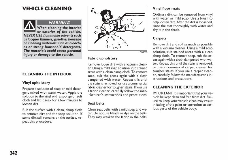
242
Fabric upholstery
Remove loose dirt with a vacuum clean-er. Using a mild soap solution, rub stainedareas with a clean damp cloth. To removesoap, rub the areas again with a clothdampened with water. Repeat this untilthe stain is removed, or use a commercialfabric cleaner for tougher stains. If you usea fabric cleaner, carefully follow the man-ufacturer’s instructions and precautions.
Seat belts
Clean seat belts with a mild soap and wa-ter. Do not use bleach or dye on the belts.They may weaken the fabric in the belts.
Vinyl floor mats
Ordinary dirt can be removed from vinylwith water or mild soap. Use a brush tohelp loosen dirt. After the dirt is loosened,rinse the mat thoroughly with water anddry it in the shade.
Carpets
Remove dirt and soil as much as possiblewith a vacuum cleaner. Using a mild soapsolution, rub stained areas with a cleandamp cloth. To remove soap, rub the ar-eas again with a cloth dampened with wa-ter. Repeat this until the stain is removed,or use a commercial carpet cleaner fortougher stains. If you use a carpet clean-er, carefully follow the manufacturer’s in-structions and precautions.
CLEANING THE EXTERIOR
IMPORTANT It is important that your ve-hicle be kept clean and free from dirt. Fail-ure to keep your vehicle clean may resultin fading of the paint or corrosion to var-ious parts of the vehicle body.
VEHICLE CLEANING
When cleaning the interioror exterior of the vehicle,
NEVER USE flammable solvents suchas lacquer thinners, gasoline, benzeneor cleaning materials such as bleach-es or strong household detergents.The materials could cause personalinjury or damage to the vehicle.
WARNING
CLEANING THE INTERIOR
Vinyl upholstery
Prepare a solution of soap or mild deter-gent mixed with warm water. Apply thesolution to the vinyl with a sponge or softcloth and let it soak for a few minutes toloosen dirt.
Rub the surface with a clean, damp clothto remove dirt and the soap solution. Ifsome dirt still remains on the surface, re-peat this procedure.
76G044A
239-244 SEDICI LUM FL GB 1E 19-06-2009 11:07 Pagina 242

243
When washing the vehicle, park it wheredirect sunlight does not fall on it and fol-low the instructions below:❒ Flush the underside of body and wheel
housings with pressurized water to re-move mud and debris. Use plenty of wa-ter.
IMPORTANTWhen washing the vehicle:❒ Avoid directing steam or hot water of
more than 80°C (176°F) on plasticparts.
❒ To avoid damaging engine components,do not use pressurized water in the en-gine compartment.
❒ Do not pour the water on the battery.And wipe off the water which remainson the battery. The water entering in-side the battery possibly causes fluidleakage.
❒ Rinse the body to loosen the dirt. Re-move dirt and mud from the body ex-terior with running water. You may usea soft sponge or brush. Do not use hardmaterials which can scratch the paintor plastic. Remember that the headlightcovers or lenses are made of plastic inmany cases.
IMPORTANT To avoid damage to thepaint or plastic surface, do not wipe thedirt off without ample water. Be sure tofollow above procedure.❒ Wash the entire exterior with a mild
detergent or vehicle wash soap usinga sponge or soft cloth. The sponge orcloth should be frequently soaked in thesoap solution.
IMPORTANT When using a commercialvehicle wash product, observe the cau-tions specified by the manufacturer. Nev-er use strong household detergents orsoaps.
– Never attempt to washand wax your vehicle with
the engine running.– When cleaning the underside of thebody and fender, where there maybe sharp-edged parts, you shouldwear gloves and a long sleeved shirtto protect your hands and arms frombeing cut.– After washing your vehicle, care-fully test the brakes before driving tomake sure they have maintainedtheir normal effectiveness.
WARNING
60B212S
WASHING
239-244 SEDICI LUM FL GB 1E 19-06-2009 11:08 Pagina 243

244
WAXING
After washing the vehicle, waxing and pol-ishing are recommended to further pro-tect and beautify the paint.
Only use waxes and polishes of good qual-ity.
When using waxes and polishes, observethe precautions specified by the manufac-turers.
❒ Once the dirt has been completely re-moved, rinse off the detergent withrunning water.
❒ After rinsing, wipe off the vehicle bodywith a wet chamois or cloth and allowit to dry in the shade.
❒ Check carefully for damage to paintedsurfaces. If there is any damage, “touch-up” the damage following the proce-dure below:
– Clean all damaged spots and allowthem to dry.
– Stir the paint and “touch- up” thedamaged spots lightly using a smallbrush.
– Allow the paint to dry completely.
IMPORTANT If you use an automatic ve-hicle wash, make sure that your vehicle’sbody parts, such as spoilers, can not bedamaged. If you are in doubt, consult thevehicle wash operator for advice.
60B211S
239-244 SEDICI LUM FL GB 1E 19-06-2009 11:08 Pagina 244

245
GGEENNEERRAALL IINNFFOORRMMAATTIIOONNVEHICLE IDENTIFICATION.............................................. 246
FUEL CONSUMPTION - CO2 EMISSIONS.................... 247
11
245-248 SEDICI LUM FL GB 1E 19-06-2009 11:09 Pagina 245

246
1. Petrol Engine Model2. Diesel Engine Model
ENGINE SERIAL NUMBER
The engine serial number is stamped onthe cylinder block as shown in the illus-tration.
VEHICLEIDENTIFICATION
CHASSIS SERIAL NUMBER
The chassis and/ or engine serial numbersare used to register the vehicle. They arealso used to assist your dealer when or-dering or referring to special service in-formation. Whenever you have occasionto consult your Fiat Dealership, remem-ber to identify your vehicle with this num-ber. Should you find the number difficultto read, you will also find it on the iden-tification plate.
79J019
60G152
For some vehicles
(2)
(1)
79J174
245-248 SEDICI LUM FL GB 1E 19-06-2009 11:09 Pagina 246

247
FUEL CONSUMPTION - CO2 EMISSIONSAccording to European Directive in force. M/T: Manual transaxle 2WD: 2-wheel drive
A/T: Automatic transaxle 4WD: 4-wheel drive
1.6 16V 2.0 Multijet
1.6 L 2WD 1.6 L 4WD 2.0 L 2WD 2.0 L 4WD
Urban (L/100km) M/T 7.9 8.2 6.4 7.0
(L/100km) A/T 9.2 – – –
Extra-urban (L/100km) M/T 5.2 5.5 4.4 4.6
(L/100km) A/T 5.9 – – –
Combined (L/100km) M/T 6.2 6.5 5.1 5.4
CO2 (g/km) M/T 143 149 134 142
(L/100km) A/T 7.2 – – –
CO2 (g/km) A/T 165 – – –
NOTE As these data are obtained under certain specific conditions, actual fuel consumption of your vehicle will be different fromthese data.
245-248 SEDICI LUM FL GB 1E 19-06-2009 11:09 Pagina 247

Page left blank voluntarily.
245-248 SEDICI LUM FL GB 1E 19-06-2009 11:09 Pagina 248

249
TTEECCHHNNIICCAALL SSPPEECCIIFFIICCAATTIIOONNSSENGINE................................................................................... 250
FUEL FEED – IGNITION..................................................... 250
ELECTRICAL COMPONENTS.......................................... 251
BULBS ...................................................................................... 251
TRANSMISSION.................................................................... 252
BRAKES ................................................................................... 252
SUSPENSIONS....................................................................... 252
STEERING............................................................................... 252
WHEELS .................................................................................. 253
DIMENSIONS......................................................................... 253
WEIGHTS ............................................................................... 254
PERFORMANCE ................................................................... 254
CAPACITIES........................................................................... 254
12
249-254 SEDICI LUM FL GB 1E 19-06-2009 11:09 Pagina 249

250
TECHNICAL SPECIFICATIONSNOTE Technical specifications are subject to change M/T: Manual transaxle 2WD: 2-wheel drivewithout notice A/T: Automatic transaxle 4WD: 4-wheel drive
ENGINE 1.6 16V 2.0 Multijet
Code - type
Number and layout of cylinders
Piston bore and stroke
Total displacement
Compression ratio
Maximum power (EEC) kWHP
corresponding ratio rpm
Maximum torque (EEC) Nmkgm
corresponding ratio rpm
Fuel
FUEL FEED - IGNITION 1.6 16V 2.0 Multijet
Fuel feed
Ignition
Modifications or repairs to the fuel feed system that are not carried out properly or do not take the system’stechnical specifications into account can cause malfunctions leading to the risk of fire.
WARNING
M16A (DOHC) - Euro 54 in line
78.0 x 83.0 mm (3.07 x 3.27 in.)
1,598 cm3 (97.5 cu. in)
10.5 : 1
88120
6,000
15615.94,400
Unleaded petrol 95 RON (Specification EN228)
D20AA - Euro 5 4 in line
83.0 x 90.4 mm (3.27 x 3.56 in.)
1,956 cm3 (119.3 cu. in)
16.5 : 1
99.2135
3,500
32032.61,500
Diesel fuel for motor vehicles(Specification EN590)
MPI electronic injection
Electronic Single Spark
Direct injection with electronically controlled Multijet Common Rail
Compression
249-254 SEDICI LUM FL GB 1E 19-06-2009 11:10 Pagina 250

251
12V – 60/55W
12V – 55W
12V – 21W
12V – 21W
12V – 5W
12V – 21/5W
12V – 5W
12V – 21W
12V – 10W
12V – 5W
12V – 21W
12V – 8W
12V – 5W
H4
H11
PY21W
P21W
W5W
P21/5W
W5W
P21W
–
–
P21W
W5W (8W)
W5W
BULBS Power Type
Main beam/dipped beam headlights
Front fog lights
Front direction indicators
Rear direction indicators
Parking lights
Brake lights / taillights
License plate lights
Reversing lights
Passenger compartment light
Luggage compartment light
Rear fog lights
Spot lights
Third brake light (additional brake light)
ELECTRICAL COMPONENTS 1.6 16V 2.0 Multijet
Battery
Spark plugs Iridium
Nickel
Fuses
12V 36Ah
NGK SILFR6A11
DENSO K16HPR-U11
12V 60Ah
––
See “INSPECTION AND MAINTENANCE” section
249-254 SEDICI LUM FL GB 1E 19-06-2009 11:10 Pagina 251

252
BRAKES
Service brakes Front
Rear
Parking brake
Vacuum brake
SUSPENSIONS
Front
Rear
STEERING
Type
Minimum steering cycle
Disc (Ø 280 mm - 11 in.) Disc (Ø 280 mm - 11 in.)
Controlled by hand lever, it works on rear brakes
10”
Mc Pherson independent wheels
Bent twisting axle
Power steering, electric
11 m (433 in.)
TRANSMISSION
Drive 4WD
Clutch
Gearbox 1.6 16V M/T
1.6 16V A/T
2.0 Multijet
4-wheel drive, electronic-control self-locking differential
Dry single disc, Belleville washer, hydraulic control
5 forward gears + reverse
4 forward gears + reverse
6 forward gears + reverse
249-254 SEDICI LUM FL GB 1E 19-06-2009 11:10 Pagina 252

253
4,115 (162.0)1,755 (69.1)1,620 (63.8)2,500 (98.4)1,495 (58.9)1,495 (58.9)
190 (7.5)270/670
4,115 (162.0)1,755 (69.1)1,620 (63.8)2,500 (98.4)1,495 (58.9)1,495 (58.9)
190 (7.5)270/670
4,115 (162.0)1,755 (69.1)1,620 (63.8)2,500 (98.4)1,495 (58.9)1,495 (58.9)
190 (7.5)270/670
4,115 (162.0)1,755 (69.1)1,620 (63.8)2,500 (98.4)1,495 (58.9)1,495 (58.9)
190 (7.5)270/670
DIMENSIONS 1.6 16V 2.0 MultijetUnit: mm (in.)
2WD 4WD 2WD 4WD
Overall lengthOverall widthOverall heightWheelbaseTrack Front
RearGround clearance (Standard A)Boot volume dm3
WHEELS
Tyre size 205/60 R16
Rim size 16 x 6J
Tyre pressures Tyre inflation pressure values are specified on the label located on the driver’s door post. When loaded up to 4 people, Eco Tire Pressure as listed below is recommended to achieve the smallest amount of fuel consumption possible.
Front 280 kPa (2.80 kg/cm², 40 psi) - Rear 260 kPa (2.60 kg/cm², 38 psi)NOTE If loading over 4 people, follow the specified tire pressure listed on the Tire Information Label.
Recommended snow chains Radial/Axial thickness:
Recommended snow tire 195/65 R15, 205/60 R16
Wheel geometry Toe-in, front
Camber angle, front 2WD
4WDCaster angle, front 2WD
4WD
10 mm (0.39 in.)
1 ± 1 mm (0.0393 ± 0.0393 in.)
− 0° 23’ ± 1°
− 0° 10’ ± 1°
3° 40’ ± 2°
3° 32’ ± 2°
249-254 SEDICI LUM FL GB 1E 19-06-2009 11:10 Pagina 253

254
2WD4WD
2WD4WD
M/TA/T
1,190 (2,623)1,250 (2,755)
1,335 (2,943)1,370 (3,020)
WEIGHTS Unit: kg (lbs) 1.6 16V 2.0 Multijet
Kerb weight (including fuel, spare wheel, tools and accessories)
185 km/h175 km/h
190 km/h180 km/h
2WD (M/T)2WD (A/T)
4WD (M/T)4WD 4WD
6.6 litres (11.6 Imp pt)6.5 litres (11.4 Imp pt)50 litres (11.0 Imp gal)3.9 litres (6.9 Imp pt)
(replacement with oil filter)2.5 litres (4.4 Imp pt)5.8 litres (10.2 Imp pt)
(when overhauling)2.5 litres (4.4 Imp pt)0.6 litres (1.1 Imp pt)0.8 litres (1.4 Imp pt)
6.5 litres (11.4 Imp pt)–
50 litres (11.0 Imp gal)4.4 litres (7.7 Imp pt)
(replacement with oil filter)2.0 litres (3.5 Imp pt)
–
2.0 litres (3.5 Imp pt)0.6 litres (1.1 Imp pt)0.8 litres (1.4 Imp pt)
PERFORMANCE 1.6 16V 2.0 Multijet
Top admitted speed after initial vehicle use
CAPACITIES (indicative values) 1.6 16V 2.0 Multijet
Coolant(including reservoir tank)
Fuel tankEngine oil
Transaxle oil
Transfer oilRear differential oil
249-254 SEDICI LUM FL GB 1E 19-06-2009 11:10 Pagina 254

255
SSUUPPPPLLEEMMEENNTTDECLARATION OF CONFORMITY ............................. 256
13
255-260 SEDICI LUM FL GB 1E 19-06-2009 13:36 Pagina 255

256
255-260 SEDICI LUM FL GB 1E 19-06-2009 13:36 Pagina 256

257
255-260 SEDICI LUM FL GB 1E 19-06-2009 13:36 Pagina 257

258
DECLARATION OF CONFORMITY
We, Calsonic Kansei Corp. hereby declare, at our sole responsibility, that the following product conforms to the EssentialRequirements of the Radio and Telecommunications Terminal Equipment Directive 1999/5/EC in accordance with the testsconducted to the appropriate requirements of the relevant standards, as listed herewith.
Product: Controller of Intelligent Key System (Keyless Start System)
Model/Type Number: S62J1
Year of affixing CE marking: 2004
DECLARATION OF CONFORMITY
We, Calsonic Kansei Corp. hereby declare, at our sole responsibility, that the following product conforms to theEssential Requirements of the Radio and Telecommunications Terminal Equipment Directive 1999/5/EC in accordance withthe tests conducted to the appropriate requirements of the relevant standards, as listed herewith.
Product: Controller of Intelligent Key System (Keyless Start System)
Model/Type Number: TS001
Year of affixing CE marking: 2004
255-260 SEDICI LUM FL GB 1E 19-06-2009 13:36 Pagina 258

259
DECLARATION OF CONFORMITY
We, Calsonic Kansei Corp. hereby declare, at our sole responsibility, that the following product conforms to the EssentialRequirements of the Radio and Telecommunications Terminal Equipment Directive 1999/5/EC in accordance with the testsconducted to the appropriate requirements of the relevant standards, as listed herewith.
Product: Transmitter of Keyless Entry System
Model/Type Number: TS002
Year of affixing CE marking: 2004
DECLARATION OF CONFORMITY
We, Calsonic Kansei Corp., of the above address, hereby declare, at our sole responsibility, that the following productconforms to the Essential Requirements of the Radio and Telecommunications Terminal Equipment Directive 1999/5/EC inaccordance with the tests conducted to the appropriate requirements of the relevant standards, as listed herewith.
Product: Transmitter of Keyless Entry System
Model/Type Number: R51K0
Year of affixing CE marking: 2007
255-260 SEDICI LUM FL GB 1E 19-06-2009 13:36 Pagina 259

Page left blank voluntarily.
255-260 SEDICI LUM FL GB 1E 19-06-2009 13:36 Pagina 260

261
– Fluid level check............................. 196– Gearshift lever ............................... 132– If you cannot shift lever out
of “P” (Park) ................................... 238– Selector position indicator .......... 89– Specific fluid .................................... 196– Using the transaxle........................ 156
Battery ................................................. 213– Replacement ................................... 214
Before driving ....................................... 9Bodywork care..................................... 239Brakes
– ABS................................................... 162– Brake fluid ....................................... 205– Brake pedal ..................................... 206– Brakes .............................................. 205– Braking ............................................. 161– Parking brake lever .................130-207– Technical specifications ................ 252– Vacuum brake ................................ 161
Bulbs– Replacement ................................... 221– Type.................................................. 251
Capacities ............................................ 254Catalytic converter.............................. 167
Children– Child-proof locks........................... 22– Child restraint systems ................ 37– Installation with Isofix type
anchorages................................... 41-42– Installation with lap-shoulder
seat belts ......................................... 42Cigar lighter .......................................... 95Clock ...................................................... 90Clutch.............................................. 131-208
– Pedal ................................................. 208Corrosion prevention......................... 240CO2 emissions...................................... 27Cruise Control..................................... 69Cup holder............................................ 142
Daily inspection checklist ................ 150Declaration of conformity ................. 256Dimensions ........................................... 253Dipped beam headlights
– Bulb replacement........................... 222– Control ............................................ 63
Doors– Central door locking system....... 13– Child-proof locks........................... 22– Dead lock........................................ 14– Door locks...................................... 12
ABS ...................................................... 162Air bags ................................................. 47
– Front ................................................ 48– General warnings........................... 55– How the system works................ 52– Servicing........................................... 54– Side ................................................... 50
Air cleaner............................................. 201Air conditioning............................. 100-104Ashtray................................................... 95Assist grips ............................................ 140Audio systems ...................................... 110
– Antenna ........................................... 113– Anti-theft system (SEC) ............... 122– Cautions on handling .................... 111– CD Changer ................................... 118– CD player........................................ 117– Error display messages................. 125– FM/MW/LW CD Player with
CD Changer control .................... 110– General ............................................ 113– Listening to a CD .......................... 112– MP3/WMA Player.......................... 120– Radio ................................................ 114– RDS (Radio Data System)............ 115– Remote audio controls ................ 126– Troubleshooting ............................ 124
Automatic Transaxle (AT) Fluid....... 196– Changing oil .................................... 197
IINNDDEEXX
14
261-268 SEDICI LUM FL GB 1E 19-06-2009 11:12 Pagina 261

262
– Level check ..................................... 192– Oil life monitoring ......................... 89– Specifications .................................. 191
Engine oil filter (change)..................... 194Engine oil life monitoring ................... 89ESP (Electronic Stability
Program)...................................... 92-164Exhaust gas............................................ 150External lights................................ 63-222
Fiat CODE (Immobilizer system) .... 11Frame hooks ........................................... 143Front fog lights........................................ 91Fuel
– Average fuel consumption (gauge) ................................................ 87
– Capacities/refuelling................... 10-254– Consumption.................................... 247– Driving range .................................... 88– Fuel filter............................................ 204– Fuel filler cap..................................... 132– Fuel gauge .......................................... 84– Fuel recommendation .................... 10– Improving fuel economy ................ 168– Instantaneous fuel consumption(gauge).................................................... 85
Fuses.......................................................... 215
Gear oil– Changing.......................................... 196
– Level check ..................................... 195– Specifications .................................. 195
Gearshift lever...................................... 132General information............................ 245Glove box.............................................. 94
Hazard warning lights ....................... 91Head restraints..................................... 30Headlight levelling switch................... 94Headlights
– Bulb replacement........................... 222– Headlight levelling switch............. 94
Heated rear window........................... 93Heating and air conditioning system.. 96
– Air outlet......................................... 96– Automatic heating and air
conditioning system (Climate Control).......................... 104
– Heating system............................... 97– Maintenance............................. 110-230– Manual heating and air
conditioning system ...................... 100Horn ....................................................... 68
Identification data .............................. 246Ignition switch ...................................... 58Information display .............................. 85Inspection and maintenance .............. 183
– Maintenance schedule................... 185– Severe driving conditions............. 190
– Keyless Start system..................... 15– Opening/closing ............................. 12
Drive belt (servicing) .......................... 191Driving tips............................................ 169
– Driving on hills ............................... 170– Driving on slippery roads ............ 171– Highway driving.............................. 170
Emergency service ............................ 231Engine
– Air cleaner ...................................... 201– Engine coolant................................ 198– Engine oil and filter........................ 191– If the engine is flooded ................. 236– If the engine overheats................. 236– If the starter does not operate... 236– Jump starting................................... 233– Oil consumption............................ 151– Serial number ................................. 246– Spark plugs ...................................... 202– Starting............................................. 152– Technical specifications ................ 249– Temperature gauge....................... 85
Engine coolant ...................................... 198Engine coolant temperature gauge .. 85Engine hood .......................................... 140Engine oil
– Changing oil and filter................... 193– Consumption.................................. 151
261-268 SEDICI LUM FL GB 1E 19-06-2009 11:12 Pagina 262

263
Mirrors– Defroster......................................... 93– Electric mirrors.............................. 28– Inside rearview mirror ................. 27– Outside rearview mirror ............. 27
MP3/WMA Player................................ 119
Odometer ........................................... 87Operating your vehicle....................... 149Original spare parts............................. 2Other controls and equipment......... 129
Parking brake lever ........................... 130Parking lights......................................... 63Pedals ..................................................... 131Performance ......................................... 254Pretensioners for seat belts .............. 45
Radio antenna...................................... 147Rear door.............................................. 23Rear fog light......................................... 64Rear window washer
– Switch............................................... 66Rear window wiper
– Blades ............................................... 229– Control ............................................ 66
Recirculated air ............................. 100-104Refuelling/Capacities .................... 10-254Remote audio controls....................... 126Roof rails or roof rack anchors........ 147Running-in.............................................. 167
Seat back pocket ................................ 145Seat belts ............................................... 31
– Height adjuster............................... 36– Pretensioners ................................. 45– Seat belt hangers............................ 36– Seat belt inspection....................... 37– Seat belt reminder (S.B.R.) .......... 35– Use.................................................... 33– Warnings ......................................... 31
Seats– Front (adjustment) ........................ 29– Front seat heater........................... 139– Seat back pocket............................ 145
Service station guide ........................... 3Shopping hook...................................... 145Snow chains .......................................... 171Spare tire........................................ 144-211Spark plugs ............................................ 202Speedometer ........................................ 84Spot light................................................ 138Starting the engine............................... 152
– If the engine is flooded ................. 236– If the starter does not operate... 236– Jump starting................................... 233
Steering .................................................. 207Steering column controls................... 57Sun visors .............................................. 137Supplement (declaration
of conformity).................................... 255
Instrument cluster ............................... 73– Meter illumination (control) ....... 90
Instrument panel ............................. 71-72Interior light.......................................... 138Isofix type child restraint system
(installation).................................. 41-42
Jack......................................................... 144Jacking instructions.............................. 232Jump starting instructions .................. 233
Keys....................................................... 11– Battery replacement ..................... 20– Keyless Entry.................................. 18
Keyless Entry System.......................... 18Keyless Start System........................... 15
Luggage compartment– Luggage compartment cover....... 146– Luggage compartment light ......... 146– Luggage restraint loops ................ 145
Main beam headlights ........................ 63– Bulb replacement........................... 222
Maintenance (programmed) .............. 183– Maintenance schedule................... 185– Severe driving conditions............. 190
Manual heating and air conditioning system.................................................. 100– Maintenance ............................ 108-230
261-268 SEDICI LUM FL GB 1E 19-06-2009 11:12 Pagina 263

264
– Inspection........................................ 208– Rotation........................................... 210– Technical data ................................ 253
Vehicle cleaning .................................. 242Vehicle identification........................... 246Vehicle loading and towing ......... 173-174Ventilation.................................98-101-107
Warning and indicator lights ........... 74Weights.................................................. 254Wheels
– Changing.......................................... 212– Technical data ................................ 253
Windows– Electric window controls............. 24– Manual window controls ............. 24
Windshield defroster..............98-101-107Windshield washer
– Control ............................................ 65– Fluid .................................................. 201
Windshield wiper– Blades ............................................... 227– Control ............................................ 65
2WD/4WD switch ....................... 92-159
Suspensions........................................... 252Symbols (battery)................................. 4
Tachometer ........................................ 83Tailgate................................................... 23Technical specifications ...................... 249Theft deterrent light ........................... 95Thermometer....................................... 88Tilt steering lock lever........................ 67Tools ...................................................... 144Towing the vehicle
– Frame hooks................................... 143– Instructions .............................. 174-179
Trailer towing....................................... 174Transaxle (automatic)......................... 156
– Changing oil .................................... 197– Fluid level check............................. 196– Specific fluid .................................... 196
Transaxle (manual) .............................. 157– Gear oil change.............................. 196– Gearshift lever ............................... 132– Specification.................................... 195– Using the transaxle........................ 157
Transmission......................................... 252Trip meter............................................. 87Turn signal............................................. 64
– Bulb replacement........................... 223Tires
– Compact spare tire....................... 211
261-268 SEDICI LUM FL GB 1E 19-06-2009 11:12 Pagina 264
PROVISIONS FOR THE PROCESSING OF A VEHICLE AT THE END OF ITS LIFE-CYCLE
For years now Fiat has been developing its global commitment towards the safeguarding and protection of the Environment throughthe continuous improvement of its production processes and the making of increasingly more “eco friendly” products. With a viewto guaranteeing the best possible service to clients in full observance of environmental standards and in response to the obligationsimposed by European Directive 2000/53/EC on end-of-life vehicles, Fiat offers its clients the possibility to hand in their vehicle* atthe end of its life span without additional costs.
The European Directive, in fact, provides for the take-back of the vehicle without the last holder or owner of the same incurring expenses due to the fact that the market value of the vehicle is zero or negative. In particular, in almost all of the countries of the European Union, up until 1st January 2007, take-back of the vehicle free of charge only applies to vehicles registered from 1 July 2002on, while, from 2007 on, take-back will be carried out free of charge, independently of the year of registration, provided that thevehicle still contains all its essential component parts (especially engine and body) and is free from additional waste materials.
Our contracted network of authorised treatment facilities has been carefully selected in order to provide a quality service to ourcustomers by de-polluting and recycling “End of Life Vehicles” to approved environmental standards. To find out the location of yournearest authorised treatment facility, offering free of charge take-back, simply contact one of our dealers or refer to the Fiat website or call the toll free number 00800 3428 0000.
* Passenger transportation vehicles to seat a max. of nine persons, having a total admissible weight of 3.5 t
261-268 SEDICI LUM FL GB 1E 19-06-2009 11:12 Pagina 265

261-268 SEDICI LUM FL GB 1E 19-06-2009 11:12 Pagina 266

261-268 SEDICI LUM FL GB 1E 19-06-2009 11:12 Pagina 267

Fiat Group Automobiles S.p.A. - Customer Services - Technical Services - Service EngineeringLargo Senatore G. Agnelli, 5 - 10040 Volvera - Torino (Italia)
Print N. 603.81.624 - 06/2009 - 1st edition
261-268 SEDICI LUM FL GB 1E 19-06-2009 11:12 Pagina 268