Embed Size (px)
Citation preview


This page intentionally left blank.

Project No. CFHWY00359
Prepared For:
State of Alaska
Department of Transportation and Public Facilities
P.O. Box 196900
Anchorage, Alaska 99519-6900
Prepared By:
Lounsbury and Associates, Inc.
5300 A Street
Anchorage, AK 99518
907.272.5451
www.lounsburyinc.com
June, 2018
The information in this report is compiled for highway safety planning purposes.
Federal law prohibits its discovery or admissibility in litigation against state, tribal or local
government that involves a location or locations mentioned in the collision data. 23 U.S.C. § 409;
23 U.S.C. § 148(g); Walden v. DOT, 27 P.3d 297, 304-305 (Alaska 2001). This compilation is derived
from reports maintained by DMV, and DOT can make no representation about their accuracy.
.

This page intentionally left blank.

i
TABLE OF CONTENTS
LIST OF FIGURES .............................................................................................................................................................. ii
LIST OF APPENDICES .................................................................................................................................................... iii
LIST OF ACRONYMS ...................................................................................................................................................... iv
1.0 PROJECT DESCRIPTION1.0 PROJECT DESCRIPTION1.0 PROJECT DESCRIPTION1.0 PROJECT DESCRIPTION ........................................................................................................................................................................................................................................................................................................................................................................................................................................................................................................................................................................................ 1111
1.1 Project Location ........................................................................................................................................... 1
1.2 Existing Conditions ...................................................................................................................................... 3
1.3 Purpose and Need ...................................................................................................................................... 4
2.0 DESIGN STANDARDS AND GUIDELINES2.0 DESIGN STANDARDS AND GUIDELINES2.0 DESIGN STANDARDS AND GUIDELINES2.0 DESIGN STANDARDS AND GUIDELINES .................................................................................................................................................................................................................................................................................................................................................................................................................................................... 4444
3.0 DISCUSSION OF ALTERNATIVES3.0 DISCUSSION OF ALTERNATIVES3.0 DISCUSSION OF ALTERNATIVES3.0 DISCUSSION OF ALTERNATIVES ................................................................................................................................................................................................................................................................................................................................................................................................................................................................................................................ 5555
4.0 SKETCH PLANNING AND INITIAL SCREENING OF ALTERNATIVES4.0 SKETCH PLANNING AND INITIAL SCREENING OF ALTERNATIVES4.0 SKETCH PLANNING AND INITIAL SCREENING OF ALTERNATIVES4.0 SKETCH PLANNING AND INITIAL SCREENING OF ALTERNATIVES ................................................................................................................................................................................................................................................ 8888
4.1 Diamond Form Alternatives ........................................................................................................................... 8
4.2 Cloverleaf Form Alternatives ....................................................................................................................... 17
5.0 5.0 5.0 5.0 ADVANCED ALTERNATIVESADVANCED ALTERNATIVESADVANCED ALTERNATIVESADVANCED ALTERNATIVES ........................................................................................................................................................................................................................................................................................................................................................................................................................................................................................................................................ 19191919
5.1 Tight Diamond Interchange ................................................................................................................... 19
5.2 Compressed Diamond Interchange with Roundabout Terminals ............................................ 22
6.0 TRAFFIC ANALYSIS6.0 TRAFFIC ANALYSIS6.0 TRAFFIC ANALYSIS6.0 TRAFFIC ANALYSIS ............................................................................................................................................................................................................................................................................................................................................................................................................................................................................................................................................................................................................ 24242424
7.0 UTILITIES7.0 UTILITIES7.0 UTILITIES7.0 UTILITIES ........................................................................................................................................................................................................................................................................................................................................................................................................................................................................................................................................................................................................................................................................................ 24242424
8.0 SOIL CONDITIONS8.0 SOIL CONDITIONS8.0 SOIL CONDITIONS8.0 SOIL CONDITIONS ................................................................................................................................................................................................................................................................................................................................................................................................................................................................................................................................................................................................................ 24242424
9.0 RIGH9.0 RIGH9.0 RIGH9.0 RIGHTTTT----OFOFOFOF----WAY REQUIREMENTSWAY REQUIREMENTSWAY REQUIREMENTSWAY REQUIREMENTS ................................................................................................................................................................................................................................................................................................................................................................................................................................................................................................ 25252525
10.0 PEDESTRIAN AND BICYCLE FACILITIES10.0 PEDESTRIAN AND BICYCLE FACILITIES10.0 PEDESTRIAN AND BICYCLE FACILITIES10.0 PEDESTRIAN AND BICYCLE FACILITIES ................................................................................................................................................................................................................................................................................................................................................................................................................................................ 28282828
11.0 STRUCTURAL SECTION AND PAVEMENT DESIGN11.0 STRUCTURAL SECTION AND PAVEMENT DESIGN11.0 STRUCTURAL SECTION AND PAVEMENT DESIGN11.0 STRUCTURAL SECTION AND PAVEMENT DESIGN ............................................................................................................................................................................................................................................................................................................................................................ 28282828
12.0 ENVIRONMENTAL12.0 ENVIRONMENTAL12.0 ENVIRONMENTAL12.0 ENVIRONMENTAL COMMITMENTS AND CONSIDERATIONSCOMMITMENTS AND CONSIDERATIONSCOMMITMENTS AND CONSIDERATIONSCOMMITMENTS AND CONSIDERATIONS .................................................................................................................................................................................................................................................................... 29292929
13.0 PUBLIC INVOLVEMENT13.0 PUBLIC INVOLVEMENT13.0 PUBLIC INVOLVEMENT13.0 PUBLIC INVOLVEMENT .................................................................................................................................................................................................................................................................................................................................................................................................................................................................................................................................................................... 30303030
14.0 CONSTRUCTABILITY CONSIDERATIONS14.0 CONSTRUCTABILITY CONSIDERATIONS14.0 CONSTRUCTABILITY CONSIDERATIONS14.0 CONSTRUCTABILITY CONSIDERATIONS .................................................................................................................................................................................................................................................................................................................................................................................................................................... 31313131
15.0 BRIDGE AND MAJOR STRUCTURES15.0 BRIDGE AND MAJOR STRUCTURES15.0 BRIDGE AND MAJOR STRUCTURES15.0 BRIDGE AND MAJOR STRUCTURES ........................................................................................................................................................................................................................................................................................................................................................................................................................................................................ 33333333
16.0 COST ESTIMATE16.0 COST ESTIMATE16.0 COST ESTIMATE16.0 COST ESTIMATE ............................................................................................................................................................................................................................................................................................................................................................................................................................................................................................................................................................................................................................ 34343434
17.0 COMPARISON OF ALTERNATIVES17.0 COMPARISON OF ALTERNATIVES17.0 COMPARISON OF ALTERNATIVES17.0 COMPARISON OF ALTERNATIVES .................................................................................................................................................................................................................................................................................................................................................................................................................................................................................... 34343434
18.0 RECOMMENDATIONS18.0 RECOMMENDATIONS18.0 RECOMMENDATIONS18.0 RECOMMENDATIONS ............................................................................................................................................................................................................................................................................................................................................................................................................................................................................................................................................................................ 36363636

ii
LIST OF FIGURES
Figure 1: Project Location and Vicinity Map ............................................................................................................ 2
Figure 2: Existing Conditions and Major Constraints ........................................................................................... 3
Figure 3: DRIAS Results ................................................................................................................................................. 6
Figure 4: Service Interchange Types .......................................................................................................................... 7
Figure 5: Compressed Diamond/ Signalized Terminals/ Existing Bridge ................................................... 10
Figure 6 : Compressed Diamond/ Roundabout Terminals/ Existing Bridge ................................................ 11
Figure 7: Compressed Diamond/ Roundabout Terminals/ New Bridge ...................................................... 12
Figure 8: Tight Diamond Interchange ..................................................................................................................... 13
Figure 9: Single Point Diamond Interchange........................................................................................................ 14
Figure 10: Single Point Diamond Interchange with Frontage Road Connectivity ..................................... 15
Figure 11: Diverging Diamond Interchange ........................................................................................................... 16
Figure 12: Two Quadrant Cloverleaf Interchange ............................................................................................... 17
Figure 13: Single Quadrant Cloverleaf Interchange ............................................................................................ 18
Figure 14: Tight Diamond Interchange Under New Bridge .............................................................................. 21
Figure 15: Roundabout Comparison ...................................................................................................................... 22
Figure 16: Roundabout Corridor .............................................................................................................................. 23
Figure 17: ROW Requirements for the TDI ........................................................................................................... 26
Figure 18: ROW Requirements for the Roundabout ......................................................................................... 27
Figure 19: Public Involvement Survey Results ...................................................................................................... 30
Figure 20: Single Span Bridge on Deck Bulb Tee Girders ................................................................................ 33
Figure 21: Construction Costs ................................................................................................................................... 34
Figure 22: Comparison Graphic ............................................................................................................................... 35

iii
LIST OF APPENDICES
APPENDIX A Preliminary Design Criteria
APPENDIX B Worksession Meeting Minutes and Presentation
APPENDIX C Construction Cost Estimates
APPENDIX D Preliminary Traffic and Safety Report
APPENDIX E Roundabout Operations Memorandum
APPENDIX F Public Involvement Plan
APPENDIX G Bridge Selection Memorandum
APPENDIX H Tight Diamond Interchange Alternative Plans
APPENDIX I Roundabout Interchange Alternative Plans

iv
LIST OF ACRONYMS
AADT Annual Average Daily Traffic
AASHTO American Association of State Highway and Transportation Officials
ADA Americans with Disabilities Act
ADEC Alaska Department of Environmental Conservation
AHDM Alaska Highway Drainage Manual
APE Area of Potential Effect
APDES Alaska Pollutant Discharge Elimination System
ARRC Alaska Railroad Corporation
ATM Alaska Traffic Manual
ATMS Alaska Traffic Manual Supplement
BMP Best Management Practice
CE Categorical Exclusion
CEA Chugach Electric Association
CFR Code of Federal Regulations
DCM Design Criteria Manual
DDI Diverging Diamond Interchange
DOT&PF Alaska Department of Transportation and Public Facilities
DRIAS Dowling Road Interchange Alternative Selection Report
DTM Digital Terrain Model
D2D Dimond Boulevard to Dowling Road
D2T Dowling Road to Tudor Road
EA Environmental Assessment
ESCP Erosion and Sediment Control Plan
EPA Environmental Protection Agency
FHWA Federal Highway Administration
HCM Highway Capacity Manual
HPCM Alaska Highway Preconstruction Manual
HMCP Hazardous Material Control Plan
HSIP Highway Safety Improvement Program
ICD Inscribed Circle Diameter
LOS Level of Service
MADT Monthly Average Daily Traffic
MIS Major Investment Study
MOA Municipality of Anchorage
MP Milepost
MPH Miles per Hour
MSE Mechanically Stabilized Earth
MUTCD Manual on Uniform Traffic Control Devices
NPDES National Pollutant Discharge Elimination System
NTP Notice to Proceed
O2D O’Malley Road to Dimond Boulevard
PARCLO Partial Cloverleaf

v
PER Preliminary Engineering Report
PGDHS A Policy on Geometric Design of Highways and Streets
PI Public Involvement
PIP Public Information Plan
PROWAG Proposed Accessibility Standards for Pedestrian Facilities in the Public Right of Way
RDG Roadside Design Guide
ROW Right-of-Way
SPDI Single Point Diamond Interchange
SWMM Storm Water Management Model
SWPPP Storm Water Pollution Prevention Plan
TCP Traffic Control Plan
TDI Tight Diamond Interchange
TMP Traffic Management Plan
USGS United States Geological Survey

1
1.0 1.0 1.0 1.0 PROJECTPROJECTPROJECTPROJECT DDDDESCRIPTIONESCRIPTIONESCRIPTIONESCRIPTION
Part of the National Highway System, the Seward Highway’s functional classification is that of
an urban principal arterial, interstate. It is defined as a freeway in the Municipality of Anchorage
(MOA) Official Streets and Highways Plan and it is a primary link in the Anchorage
transportation system. Since the early 2000’s the Department of Transportation and Public
Facilities (DOT&PF) has been reconstructing the Seward Highway from Rabbit Creek to Tudor
Road. The reconstruction program improves the facility from a four-lane, divided, controlled
access highway to a six-lane, divided, controlled access highway.
DOT&PF has completed a Major Investment Study (MIS) and an Environmental Assessment (EA)
that contain recommendations and commitments for the program (New Seward Highway
Environmental Assessment, 2007). These governing documents identified the reconstruction of
the interchange between the Seward Highway and Dowling Road as a central component of
the overall program.
This Preliminary Engineering Report has been prepared to document the design decisions used
to select a build alternative for the reconstruction of this interchange. The DOT&PF’s selected
build alternative will be advanced to detailed design and bid ready documents in order to
support a 2020 construction project. These improvements will accommodate the anticipated
traffic volumes for the year 2040.
1.11.11.11.1 ProjectProjectProjectProject LocationLocationLocationLocation
The project is located at the interchange between the Seward Highway and Dowling Road,
within the MOA. It is located between the Dimond Boulevard and Tudor Road interchanges, at
approximate latitude 61.166400 and approximate longitude -149.852766. The work
encompasses portions of adjacent frontage roads Brayton Drive and Homer Drive, and ramps in
all four quadrants of the interchange. See Figure 1 on Page 2 for Project Location and Vicinity
Map and Figure 2 on Page 3 for the Existing Conditions and Major Constraints.

2
Figure Figure Figure Figure 1:1:1:1: Project Location and Vicinity MapProject Location and Vicinity MapProject Location and Vicinity MapProject Location and Vicinity Map

3
1.21.21.21.2 ExistingExistingExistingExisting ConditionsConditionsConditionsConditions
The Seward Highway/Dowling Road interchange is a diamond form interchange with ramps
in all four quadrants that terminate at a pair of two-lane roundabouts. The mainline, ramps
and frontage roads south of Dowling Road are currently being reconstructed as part of the
Seward Highway: Dimond Boulevard to Dowling Road (D2D) reconstruction project. The
corridor north of Dowling Road was recently reconstructed as part of the Dowling Road to
Tudor Road (D2T) reconstruction project. These two projects expanded the Seward
Highway from a 4 lane divided facility to a 6 lane divided facility. Because neither project
replaced the existing Dowling Road bridge, the Seward Highway mainline was reduced in
cross section in order to fit six travel lanes over the existing bridge. This also required the
elimination of the median, along with reduced shoulder widths and median barriers.
The roundabout terminals were constructed in 2003. The roundabouts replaced poorly
operating signals and were Alaska’s first multi-lane roundabouts. They were designed to
accommodate projected traffic in the year 2020. The roundabouts were constructed to fit
within limited space, constrained by tight Right-of-Way (ROW) and the existing highway
bridge. A high voltage Chugach Electric Association transmission line runs east-west along
the south side of Dowling Road. Impacts to the transmission line are undesirable and are a
significant geometric constraint. Running sands, a high ground water table, and the
presence of deep peat constitute the existing geotechnical conditions at the interchange.
Figure 2Figure 2Figure 2Figure 2:::: Existing Conditions and Major ConstraintsExisting Conditions and Major ConstraintsExisting Conditions and Major ConstraintsExisting Conditions and Major Constraints

4
The one-way frontage roads Brayton Drive (northbound) on the east, and Homer Drive
(southbound) on the west, join the ramps in all four quadrants. These frontage roads
provide through movement connectivity for businesses and residents along the corridor,
and provide emergency redundancy in the system by providing mainline detour/bypass
capacity. Figure 2 shows the current configuration of the interchange and the associated
constraints.
1.31.31.31.3 PurposePurposePurposePurpose and Needand Needand Needand Need
This project is part of the broader Seward Highway Reconstruction: Rabbit Creek Road to
Tudor Road environmental document. The purpose and need statement for the overall
corridor is focused on reconstructing the Seward Highway with improvements that address
current and future travel demand and mobility needs by providing additional capacity,
connectivity and safety enhancements.
Working within the prior commitments and parameters of the reconstruction program, the
objective of this project is to develop reasonable and feasible alternatives for a
reconstructed interchange at Dowling Road in sufficient detail to select a build alternative.
Specifically, the purpose of this work is to:
1. Review previous concepts and recommendations for the interchange and develop
additional concepts as appropriate.
2. Determine if the Dowling Road bridge will be replaced with a new structure that
accommodates the full build cross section of the Seward Highway mainline.
3. Determine if the through movements on the one-way frontage road systems are to
be preserved with the interchange configuration.
The work requires an evaluation of ROW and environmental impacts, design year 2040
traffic and safety performance, and development of cost estimates.
2.0 2.0 2.0 2.0 DESIGNDESIGNDESIGNDESIGN STANDARDS AND GUIDELINESSTANDARDS AND GUIDELINESSTANDARDS AND GUIDELINESSTANDARDS AND GUIDELINES
Design standards and guidelines that apply to the Seward Highway/Dowling Road Interchange
Reconstruction Project are contained in the following publications:
Standards:
• A Policy on Geometric Design of Highways and Streets (PGDHS), 6th Edition, American
Association of State Highway and Transportation Officials (AASHTO), 2011.
• Roadside Design Guide (RDG), 4th Edition, AASHTO, 2011.

5
• Alaska Highway Preconstruction Manual (HPCM), State of Alaska, DOT&PF, 2005 as
amended.
• Alaska Highway Drainage Manual (AHDM), State of Alaska, DOT&PF, 2006.
• The Alaska Traffic Manual (ATM), consisting of the Manual on Uniform Traffic Control
Devices (MUTCD), 2009 as amended, U.S. DOT, Federal Highway Administration (FHWA)
and the Alaska Traffic Manual Supplement (ATMS), State of Alaska, DOT&PF, 2016.
• ADA Standards for Transportation Facilities, U.S. DOT, 2006.
• ADA Standards for Accessible Design, United States Department of Justice, 2010.
• Guide for the Development of Bicycle Facilities, 4th Edition, AASHTO, 2012.
• Recommended Practice for Roadway Lighting (RP-8-14), American National Standards
Institute / Illuminating Engineering Society, 2014.
• Highway Capacity Manual (HCM), 5th Edition, Transportation Research Board, 2010.
• Design Criteria Manual (DCM), Municipality of Anchorage, Project Management &
Engineering Department, 2007.
Guidelines:
• Proposed Accessibility Standards for Pedestrian Facilities in the Public Right-of-Way
(PROWAG), United States Access Board, 2011.
• Guide for the Planning, Design, and Operation of Pedestrian Facilities, 1st Edition, AASHTO,
2004.
Appendix A contains the preliminary Design Criteria. These criteria are replications of the criteria
used for the recent Seward Highway Reconstruction projects from Dimond Boulevard to Dowling
Road, and from Dowling Road to Tudor Road. They will be updated as appropriate and finalized
with detailed design.
3.03.03.03.0 DISCUSSION OF ALTERNATIVESDISCUSSION OF ALTERNATIVESDISCUSSION OF ALTERNATIVESDISCUSSION OF ALTERNATIVES
Numerous multimodal highway improvements were analyzed during the development of the
original EA. These included a no build alternative, 8-lane expansion of the highway, provisions
for high occupancy vehicle lanes, conversion to two-way frontage road systems, and various
transportation system management techniques.
The preferred alternative identified expanding the Seward Highway mainline to six lanes,
reconstructing frontage roads and ramps, improving pedestrian facilities along the corridor,

6
providing grade separated crossings at 92nd Avenue, 76th Avenue, 68th Avenue, Campbell
Creek, and International Airport Road, and reconstructing the bridges at Dimond Boulevard,
Dowling Road and Tudor Road.
To date, the corridor has been reconstructed from just north of Dowling Road to Tudor Road
and portions of the grade separation at 92nd Avenue have been constructed. The segment
from Dimond Boulevard to just south of Dowling Road is currently in construction, and the
segment from O’Malley Road, north to Dimond Boulevard (O2D) is currently in design. The
interchange and associated Seward Highway in the immediate vicinity of Dowling Road has not
been reconstructed. This project will complete the link between the D2D and D2T projects.
During the Design Study Phase of the D2D project, detailed design options were developed
and evaluated for the build alternative for the Dowling Road interchange. This work was
documented in a Dowling Road Interchange Alternative Selection Report (DRIAS, CH2M Hill,
2013). Specifically, the work in the DRIAS evaluated:
1. Improvements to the existing roundabouts
2. Converting to a Tight Diamond Interchange (TDI)
3. Converting to a Single Point Diamond Interchange (SPDI)
4. Converting to a Diverging Diamond Interchange (DDI)
5. Converting to a Partial Cloverleaf Interchange (Parclo)
A TDI was identified as the preferred alternative because it was found to be operationally
acceptable for the future capacity given the best available data at the time, and had the
advantages of a smaller footprint than other alternatives. Figure 3 shows a summary of the
results of the previous study.
Figure 3: DRIAS ResultsFigure 3: DRIAS ResultsFigure 3: DRIAS ResultsFigure 3: DRIAS Results
7
The work of this PER builds on the work of the previous study with the added benefit of
updated traffic projections and newly acquired ROW. Additionally, the DDI interchange type
has recently been constructed in the region and is currently planned for future construction on
this corridor. DDI’s did not exist in Alaska at the time of the previous study and they were
dismissed, in part, because they did not meet driver expectations and were not consistent with
other interchange types on the corridor. This is no longer the case.
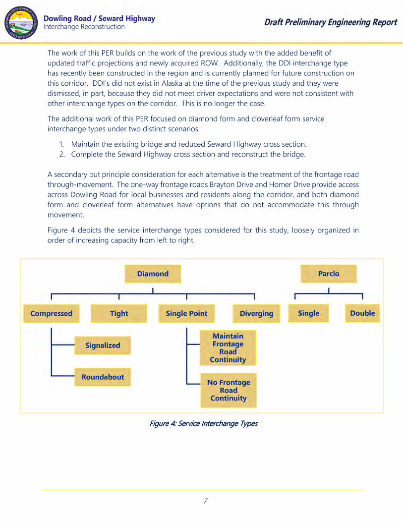
The additional work of this PER focused on diamond form and cloverleaf form service
interchange types under two distinct scenarios:
1. Maintain the existing bridge and reduced Seward Highway cross section.
2. Complete the Seward Highway cross section and reconstruct the bridge.
A secondary but principle consideration for each alternative is the treatment of the frontage road
through-movement. The one-way frontage roads Brayton Drive and Homer Drive provide access
across Dowling Road for local businesses and residents along the corridor, and both diamond
form and cloverleaf form alternatives have options that do not accommodate this through
movement.
Figure 4 depicts the service interchange types considered for this study, loosely organized in
order of increasing capacity from left to right.
Figure 4: Service Interchange TypesFigure 4: Service Interchange TypesFigure 4: Service Interchange TypesFigure 4: Service Interchange Types

8
4.0 SKETCH PLANNING AND INITIAL SCREENING OF 4.0 SKETCH PLANNING AND INITIAL SCREENING OF 4.0 SKETCH PLANNING AND INITIAL SCREENING OF 4.0 SKETCH PLANNING AND INITIAL SCREENING OF ALTERNATIVESALTERNATIVESALTERNATIVESALTERNATIVES
The interchange types depicted in Figure 4 were developed as site specific detailed sketches and
organized to demonstrate each type’s advantages and disadvantages. The Sketches were
prepared as an initial screening activity and were presented at a half-day sketch planning/work
session with the DOT&PF and the MOA. The sketch planning session resulted in two critical
decisions that caused the majority of the alternatives to be dropped from further consideration.
These decisions were:
1. Complete the Seward Highway mainline expansion and replace the bridge
2. Maintain the frontage road through movement
Based on these decisions, two alternatives were selected for advancement to preliminary design
and cost estimating. The worksession presentation and meeting minutes are contained in
Appendix B and summarized below.
4.14.14.14.1 Diamond Form AlternativesDiamond Form AlternativesDiamond Form AlternativesDiamond Form Alternatives
All service interchanges in the diamond form family feature one-way ramps in all four
quadrants of the interchange. They are commonly used in both rural and urban
environments and have a high degree of driver familiarity. The type of diamond is a
function of the ramp terminal spacing, ramp control techniques, and the cross section of the
minor road. Service interchange alternatives in the diamond form family include
compressed diamonds, tight diamonds, single point diamonds and diverging diamonds.
Each has distinct advantages and disadvantages.
The FHWA maintains an online interactive design tool that describes diamond form
alternatives in detail. (https://www.fhwa.dot.gov/modiv/programs/intersta/idp.cfm). The
following is a summary of the FHWA’s definitions of compressed and tight diamonds and a
discussion of how these definitions are applied to this project.
Compressed diamond form interchanges feature ramp spacing between 400’ and 800’ feet
apart and they are suitable for use where ROW is constrained. These diamond forms can
utilize traffic signal or roundabout terminals and both configurations are common along the
corridor.
Traffic signal phasing at compressed diamonds typically aims to progress minor street
through movements through the interchange, while storing left-turning vehicles between
the ramp terminals. From a capacity perspective, signal-controlled compressed diamonds
are one of the least efficient diamond forms. Under high volumes of traffic, obtaining signal
progression and providing sufficient queue storage can prove difficult. As such, the FHWA
recommends their use in rural or suburban settings where traffic demands are low to
moderate.

9
The actual spacing of the ramp terminals has very little effect on the operational
performance of roundabout terminals, as interior queuing is minimal due to nominal
conflicting traffic. However, other criteria such as entrance and exit geometry, inscribed
circle diameters, fastest path considerations and sight distance, constitute the predominate
performance parameters.
Tight diamond form interchanges feature ramp spacing between 250’ to 400’ apart. Both
roundabout terminals and signalized terminals can be applied in a tight diamond
configuration. Signalized tight diamonds require close coordination between each ramp
signal. With proper signal timing, they are a high capacity interchange form that progress
nearly all vehicles through the interchange and store vehicles outside of the interchange,
along the minor street.
The existing Dowling Road interchange features roundabout ramp terminals spaced
approximately 390 feet apart, on the boundary between the tight and compressed diamond
definitions. This requires some further clarification for the purpose of this report.
The roundabout alternatives described below feature ramp terminals that closely match the
spacing of the existing interchange at the boundary of the tight/compressed definition.
This report refers to these alternatives simply as compressed diamond form interchanges.
Alternatively, these could simply be thought of as diamond form interchanges featuring
roundabout terminals, where the exact definition of “tight” or “compressed” is somewhat
arbitrary in nature.
This is not the case with signalized alternatives because the spacing of the ramps is pivotal
to the signal phasing approach and the resulting operations of signalized terminals. For
signalized terminals, this study considers tight diamonds as diamond form interchanges
near the lower limit of the strict definition, on the order of 250' ramp terminal spacing. The
signalized alternatives that are on the boundary, approaching 400' spacing, are treated as
compressed diamond forms.

10
Compressed DiamondCompressed DiamondCompressed DiamondCompressed Diamond / Signalized Terminals/ Signalized Terminals/ Signalized Terminals/ Signalized Terminals:
Figure 5 shows a compressed diamond
form with signalized terminals under the
existing bridge.
This represents a familiar interchange
type to motorists and is an alternative
that could preserve the existing bridge
structure, requiring little to no new ROW
to construct.
This alternative features no
improvements to the Seward Highway
mainline, maintaining the reduced cross
section, median and shoulder widths.
Minor ramp and frontage road work
would be required to reconnect the
ramps to Dowling Road, and the
frontage road through movement would
be retained. The existing roundabout
terminals would be converted to
signalized terminals in approximately the
same location. Improvements to
Dowling Road would be nominal, and
maintaining the bridge effectively
precludes providing for left turn lanes
under the structure.
Operationally, simply converting the
roundabout to signalized terminals
would not meet the future travel
demand. The only advantage to this
alternative was the preservation of the
existing bridge. Since a new bridge is
required, this alternative was not
advanced to preliminary engineering.
Figure 5: Compressed Diamond/ Figure 5: Compressed Diamond/ Figure 5: Compressed Diamond/ Figure 5: Compressed Diamond/ Signalized Terminals/ Signalized Terminals/ Signalized Terminals/ Signalized Terminals/
Existing BridgeExisting BridgeExisting BridgeExisting Bridge

11
Compressed Diamond / Roundabout Terminals:Compressed Diamond / Roundabout Terminals:Compressed Diamond / Roundabout Terminals:Compressed Diamond / Roundabout Terminals:
Figure 6 shows a compressed diamond
form with roundabout terminals under
the existing bridge. This is the form in
place at the interchange today.
No improvements are proposed to the
Seward Highway mainline with this
alternative. The existing bridge structure
and reduced highway cross section,
shoulder widths, and median are
retained.
Substantial realignment of the ramps
would be required to provide the
geometry for suitable performance. This
is particularly apparent at the north and
southbound off ramps. Nominal
reconstruction of the frontage roads is
required to reconnect them with the
realigned ramps, and the through
movement is retained.
Variable inscribed diameters are applied
to the roundabout circles, which are
proposed slightly further apart than the
existing configuration.
By taking advantage of newly acquired
ROW, this represents an improvement
over the existing condition.
Operationally, at the sketch planning
level, this alternative showed promise at
meeting the future travel demand. It was
dismissed from further consideration with
the decision to replace the highway
bridge.
FFFFigure 6 : Compressed Digure 6 : Compressed Digure 6 : Compressed Digure 6 : Compressed Diamond/iamond/iamond/iamond/
RoundaboutRoundaboutRoundaboutRoundabout TTTTerminals/erminals/erminals/erminals/ Existing BExisting BExisting BExisting Bridgeridgeridgeridge
12
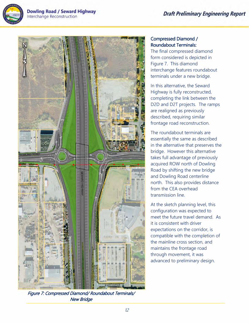
Compressed Diamond / Compressed Diamond / Compressed Diamond / Compressed Diamond /
Roundabout Terminals:Roundabout Terminals:Roundabout Terminals:Roundabout Terminals:
The final compressed diamond
form considered is depicted in
Figure 7. This diamond
interchange features roundabout
terminals under a new bridge.
In this alternative, the Seward
Highway is fully reconstructed,
completing the link between the
D2D and D2T projects. The ramps
are realigned as previously
described, requiring similar
frontage road reconstruction.
The roundabout terminals are
essentially the same as described
in the alternative that preserves the
bridge. However this alternative
takes full advantage of previously
acquired ROW north of Dowling
Road by shifting the new bridge
and Dowling Road centerline
north. This also provides distance
from the CEA overhead
transmission line.
At the sketch planning level, this
configuration was expected to
meet the future travel demand. As
it is consistent with driver
expectations on the corridor, is
compatible with the completion of
the mainline cross section, and
maintains the frontage road
through movement, it was
advanced to preliminary design.
FiFiFiFigure 7:gure 7:gure 7:gure 7: Compressed Diamond/ Roundabout Terminals/ Compressed Diamond/ Roundabout Terminals/ Compressed Diamond/ Roundabout Terminals/ Compressed Diamond/ Roundabout Terminals/
NewNewNewNew BridgeBridgeBridgeBridge

13
Tight DiamondTight DiamondTight DiamondTight Diamond: Tight diamond form
interchanges are widely used as
service interchanges. They are very
efficient diamond form interchanges
that feature closely spaced, signalized
ramp terminals. Their efficiency
comes from the ability to coordinate
signal timing. Because both
intersections are so closely spaced,
they can be operated and controlled
as a single intersection, which can be
coordinated with adjacent signalized
intersections. While few interchanges
are operated as tight diamonds in
Alaska, the lane configurations would
be similar to the Seward
Highway/Tudor Road interchange.
In this alternative, the Seward
Highway mainline is fully
reconstructed and a new bridge is
provided. Major realignments of the
ramps are required in all four
quadrants in order to provide the
250’ spacing between ramp
terminals. This tight spacing requires
the use of retaining walls along the
Seward Highway mainline. Frontage
roads require reconstruction to
reconnect with the new ramp
locations, and the through movement
can be preserved.
Dowling Road is realigned to the
north similar to the roundabout
alternative shown in Figure 7 and the
cross section features dual left turn
lanes under the new bridge.
This interchange type was
recommended in the DRIAS and is
expected to accommodate the travel
demand. This alternative was
advanced to preliminary design. FFFFigure 8:igure 8:igure 8:igure 8: Tight Diamond InterchangeTight Diamond InterchangeTight Diamond InterchangeTight Diamond Interchange
14
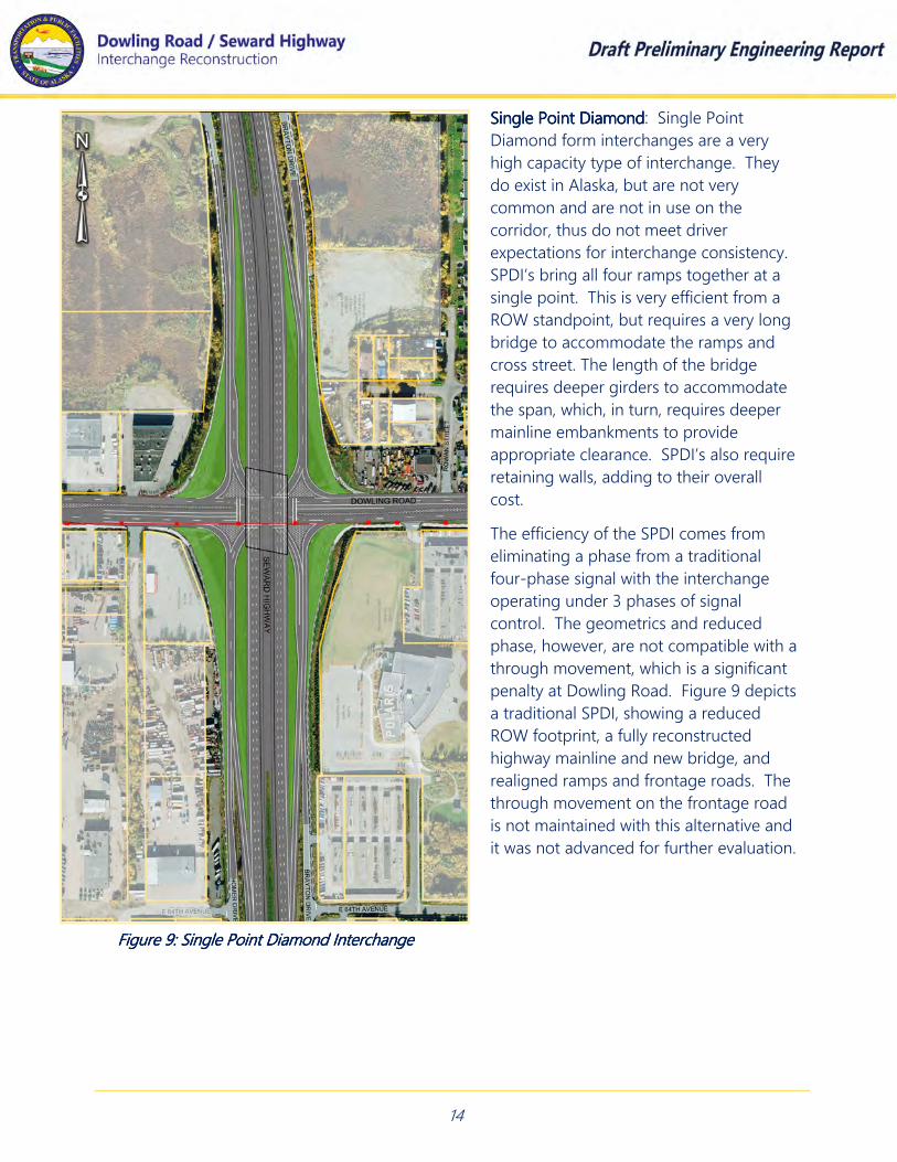
Single Point DiamondSingle Point DiamondSingle Point DiamondSingle Point Diamond: Single Point
Diamond form interchanges are a very
high capacity type of interchange. They
do exist in Alaska, but are not very
common and are not in use on the
corridor, thus do not meet driver
expectations for interchange consistency.
SPDI’s bring all four ramps together at a
single point. This is very efficient from a
ROW standpoint, but requires a very long
bridge to accommodate the ramps and
cross street. The length of the bridge
requires deeper girders to accommodate
the span, which, in turn, requires deeper
mainline embankments to provide
appropriate clearance. SPDI’s also require
retaining walls, adding to their overall
cost.
The efficiency of the SPDI comes from
eliminating a phase from a traditional
four-phase signal with the interchange
operating under 3 phases of signal
control. The geometrics and reduced
phase, however, are not compatible with a
through movement, which is a significant
penalty at Dowling Road. Figure 9 depicts
a traditional SPDI, showing a reduced
ROW footprint, a fully reconstructed
highway mainline and new bridge, and
realigned ramps and frontage roads. The
through movement on the frontage road
is not maintained with this alternative and
it was not advanced for further evaluation.
Figure 9: Single Point Diamond InterchangeFigure 9: Single Point Diamond InterchangeFigure 9: Single Point Diamond InterchangeFigure 9: Single Point Diamond Interchange

15
Single Point Diamond with frontage Single Point Diamond with frontage Single Point Diamond with frontage Single Point Diamond with frontage
through movement:through movement:through movement:through movement: Figure 10 depicts an
alternative of an SPDI that was developed
to accommodate the frontage road
through movement.
This alternative fully reconstructs the
Seward Highway mainline, complete with
a new bridge, and realigns the ramps and
frontage roads similarly to the alternative
shown in Figure 9. This version of an
SPDI was evaluated in detail with the
previous DRIAS study.
The difference between this alternative
and the more traditional SPDI is that an
additional phase in the signal is
incorporated to allow for a movement
across Dowling Road. Completing this link
and introducing a fourth phase of signal
control eliminates the efficiency of the
interchange type. This effectively
eliminates the benefits of the SPDI
configuration. This would not be
expected to accommodate the travel
demand and it was not advanced for
further evaluation.
Figure 10:Figure 10:Figure 10:Figure 10: Single Point Diamond Interchange with Single Point Diamond Interchange with Single Point Diamond Interchange with Single Point Diamond Interchange with
Frontage Road ConnectivityFrontage Road ConnectivityFrontage Road ConnectivityFrontage Road Connectivity

16
Diverging Diamond InterchangeDiverging Diamond InterchangeDiverging Diamond InterchangeDiverging Diamond Interchange:
Diverging Diamond Interchanges are new
to Alaska with one recently constructed at
the Glenn Highway/Muldoon Road
interchange. Just south of Dowling Road,
two DDI’s are proposed to retrofit the
Dimond Boulevard and O’Malley Road
interchanges. DDI’s are an innovative way
to significantly increase the capacity of an
interchange, and they are commonly used
as a retrofit technique to preserve an
existing structure where interchange
improvements are needed.
DDI’s are considered to be one of the
highest capacity diamond form of
interchange. Their efficiency comes from
the use of two signals located outside of
the interchange that are used to cross
traffic over prior to entering the
interchange, converting left turns into free
movements, avoiding the inefficient left-
turn signal phases, reducing vehicle
conflicts, and minimizing queue storage
needs.
Figure 11 depicts a site specific layout of a
DDI. This alternative represents a retrofit
technique for the Dowling Road
interchange that maintains the existing
bridge. No changes to the Seward
Highway are required to accommodate
this alternative. The ramps would be
slightly reconfigured to connect with the
cross over lanes on Dowling Road. The
frontage roads are essentially untouched
with this alternative, but the through
movement across Dowling Road would
not be accommodated. This alternative
was dismissed from consideration with
the decision to replace the Seward
Highway bridge and maintain the
frontage road connectivity.
Figure 11: Diverging Diamond InterchangeFigure 11: Diverging Diamond InterchangeFigure 11: Diverging Diamond InterchangeFigure 11: Diverging Diamond Interchange
17
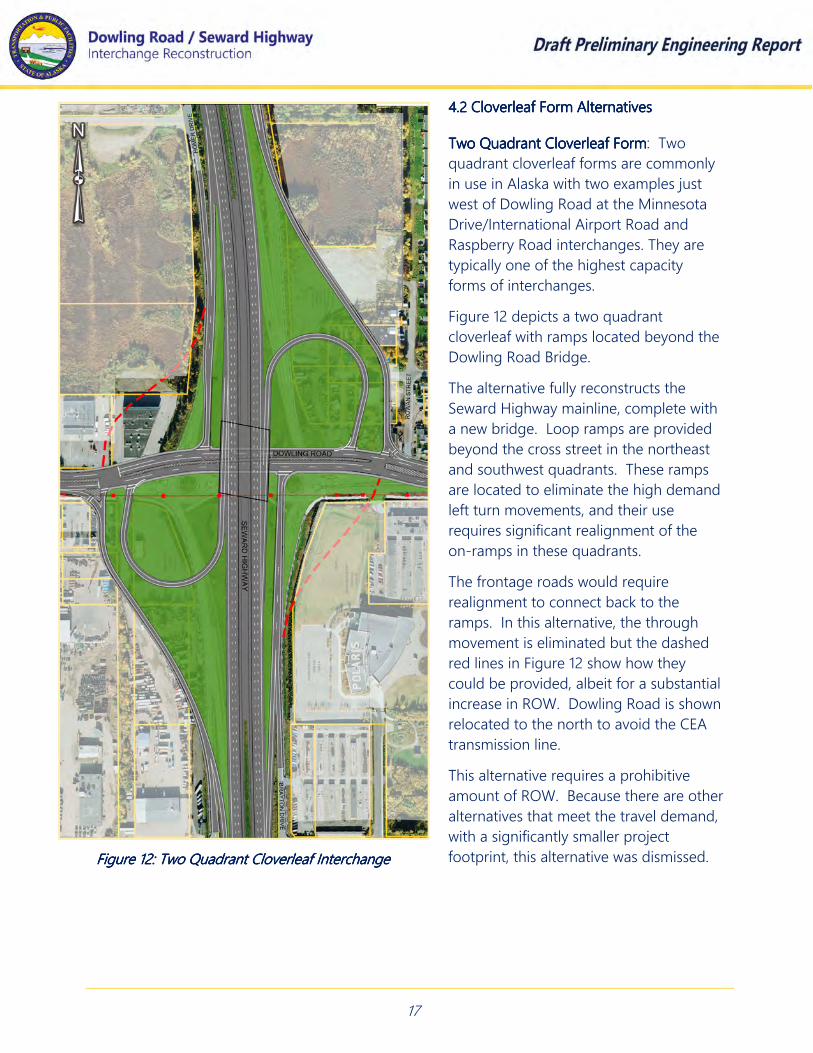
4.24.24.24.2 Cloverleaf Form AlternativesCloverleaf Form AlternativesCloverleaf Form AlternativesCloverleaf Form Alternatives
Two Quadrant Two Quadrant Two Quadrant Two Quadrant Cloverleaf FormCloverleaf FormCloverleaf FormCloverleaf Form: Two
quadrant cloverleaf forms are commonly
in use in Alaska with two examples just
west of Dowling Road at the Minnesota
Drive/International Airport Road and
Raspberry Road interchanges. They are
typically one of the highest capacity
forms of interchanges.
Figure 12 depicts a two quadrant
cloverleaf with ramps located beyond the
Dowling Road Bridge.
The alternative fully reconstructs the
Seward Highway mainline, complete with
a new bridge. Loop ramps are provided
beyond the cross street in the northeast
and southwest quadrants. These ramps
are located to eliminate the high demand
left turn movements, and their use
requires significant realignment of the
on-ramps in these quadrants.
The frontage roads would require
realignment to connect back to the
ramps. In this alternative, the through
movement is eliminated but the dashed
red lines in Figure 12 show how they
could be provided, albeit for a substantial
increase in ROW. Dowling Road is shown
relocated to the north to avoid the CEA
transmission line.
This alternative requires a prohibitive
amount of ROW. Because there are other
alternatives that meet the travel demand,
with a significantly smaller project
footprint, this alternative was dismissed. Figure 12: Two Quadrant Cloverleaf InterchangeFigure 12: Two Quadrant Cloverleaf InterchangeFigure 12: Two Quadrant Cloverleaf InterchangeFigure 12: Two Quadrant Cloverleaf Interchange

18
Single Quadrant Cloverleaf FormSingle Quadrant Cloverleaf FormSingle Quadrant Cloverleaf FormSingle Quadrant Cloverleaf Form:::: A single
quadrant cloverleaf form, with a loop in
the southwest quadrant is shown in Figure
13.
At the sketch planning level, the traffic
analysis indicated that the loop in the
southwest quadrant would serve 750
vehicles per hour in the PM peak,
justifying the use of the loop ramp. Peak
demands for the northbound to
westbound left turn are substantially less,
and the use of the loop in the northeast
quadrant shown in Figure 12 is not
required.
This single quadrant cloverleaf form
features a loop ramp in the southwest
quadrant of the interchange. The east
terminal includes a signalized intersection
but a roundabout terminal could also be
considered for this alternative.
The Seward Highway mainline
improvements are identical to the two
quadrant loop alternative. The ramps and
frontage roads require less realignment
than the two loop option. Homer Drive on
the west is shown without a through
movement connection, but a connection
could be accommodated as shown in
Figure 12. Dowling Road is also similarly
relocated to the north to avoid the
transmission line and to minimize ROW
requirements along the cross street.
The ROW impacts are substantial and
there are other diamond form
interchanges with higher capacity than a
single quadrant cloverleaf. For these
reasons, this alternative was dismissed.
Figure 13: Single Quadrant Cloverleaf InterchangeFigure 13: Single Quadrant Cloverleaf InterchangeFigure 13: Single Quadrant Cloverleaf InterchangeFigure 13: Single Quadrant Cloverleaf Interchange

19
Alternatives advanced to Preliminary Engineering:Alternatives advanced to Preliminary Engineering:Alternatives advanced to Preliminary Engineering:Alternatives advanced to Preliminary Engineering: Nine alternatives were developed as
detailed site specific sketches and presented at the sketch planning worksession. These
included seven diamond form interchanges and two cloverleaf alternatives. The diamond
form alternatives featured three options that preserved the existing bridge structure and four
that required a new bridge. Both cloverleaf options require a new bridge.
Two alternatives, the single point diamond and the diverging diamond, are not compatible
with the through movement on the frontage road. Three other alternatives can provide this
movement at a substantial loss of utility to the interchange (SPDI w/ frontage road) or
require a prohibitive amount to ROW to accommodate (both cloverleaf alternatives).
With the decision to complete the Seward Highway mainline and reconstruct the bridge, and
the requirement to preserve the through movement on the one way frontage road, the
majority of alternatives were eliminated as candidates for further design and analysis. Only
the cloverleaf alternatives and the signalized tight diamond and compressed diamond with
roundabout terminals satisfy both parameters. Both cloverleaf alternatives require a
prohibitive amount of ROW to construct and do not provide any substantial advantages over
the other candidates to warrant further development.
The compressed diamond interchange with roundabout terminals and the tight diamond
interchange both accommodate the full build mainline cross section and maintain the
through movement on the frontage road. These also feature footprints that can reasonably
be constructed at this interchange. Both alternatives were advanced to the preliminary
engineering level of analysis.
5.0 5.0 5.0 5.0 ADVANCEDADVANCEDADVANCEDADVANCED ALTERNATIVESALTERNATIVESALTERNATIVESALTERNATIVES
The preliminary engineering analysis required developing each alternative to the 30% level of
detail, including horizontal and vertical geometric design and three-dimensional digital terrain
modeling (DTM). The development of DTM’s for each alternative were used to prepare planning
level construction cost estimates and depict draft project footprints including cut and fill limits.
Each alternative is described as follows:
5.15.15.15.1 Tight Diamond InterchangeTight Diamond InterchangeTight Diamond InterchangeTight Diamond Interchange
The TDI alternative features a six lane expanded mainline and reconstruction of all four ramp
and frontage road connections to the interchange. The mainline work begins just south of
Dowling Road, where the previous D2D project transitions from the ultimate full build cross
section, to the reduced interim cross section. The cross section is completed from the end of
the D2D project to the beginning of the D2T project, completing the full build of the Seward
Highway mainline expansion.

20
The horizontal alignment and profile grade of the mainline closely match the existing
geometry. The auxiliary lanes to and from the north are maintained as is the southbound
auxiliary lane between Dowling Road and Dimond Boulevard. Both off ramps are lengthened,
departing earlier from the mainline in order to increase the ramp length and provide more
weave length for ramp and frontage road traffic operations.
Signalized terminals are shown spaced approximately 250’ apart, at the lower limit of the
formal definition of a tight diamond. This tight ramp spacing requires longitudinal retaining
walls along the mainline to retain the roadway embankment. The close spacing shown
represents the “worst case” with respect to the heights of the walls. If the TDI is selected as the
build alternative, further design efforts would seek to increase the ramp terminal spacing while
simultaneously seeking to balance signal timing, in an effort to reduce the required retaining
wall height.
A new Seward Highway bridge with six mainline lanes and fully developed shoulder and
median widths would span Dowling Road. Four different bridge types were considered for the
alternative. A single span bridge on shallow foundations consisting of 5.5’ deep deck bulb tee
girders is used in the preliminary design as the most likely bridge type for the project. The
bridge proposed would be at the maximum limit for bridge length for a single span bridge
with this girder type, and vertical abutment walls would be needed to provide the required
width for Dowling Road.
In the alternative, the centerline of Dowling Road is re-aligned approximately 30 feet to the
north. This realignment eliminates impacts along the south of the alignment, and allows for
the reconstruction to avoid impacting the CEA transmission line and associated power poles.
Similar to the TDI shown in the DRIAS report, this realignment would require new ROW along
Dowling Road at the east and west ends of the improvements where the realigned geometry
transitions back to the existing centerline.
The profile grade of Dowling Road is shown slightly lowered from the existing profile in order
to provide clearance underneath the mainline bridge girders. Slightly more clearance has
been provided than what is required by the Preconstruction Manual for this preliminary design.
The profile is designed with respect to several topographic surveys and design surfaces of
various vintages. With an accurate survey of the existing ground at the new centerline it is
likely that the cut along Dowling Road can be minimized or eliminated.
Dowling Road’s cross section under the new bridge features dual left turn lanes and two
through lanes each in the east and west direction, for a total of 8 lanes under the new bridge
structure. Pedestrians are accommodated by a combination of 10’ wide pathways along
Dowling Road and 5’ wide sidewalks and bikeways on the frontage road approaches to the
cross street. Figure 14 depicts the TDI corridor as developed to the preliminary engineering
level of design.

21
Figure 14: Tight Diamond Interchange Under New BridgeFigure 14: Tight Diamond Interchange Under New BridgeFigure 14: Tight Diamond Interchange Under New BridgeFigure 14: Tight Diamond Interchange Under New Bridge

22
5.25.25.25.2 Compressed Diamond Interchange with Roundabout TerminalsCompressed Diamond Interchange with Roundabout TerminalsCompressed Diamond Interchange with Roundabout TerminalsCompressed Diamond Interchange with Roundabout Terminals
The compressed diamond with roundabout terminals alternative features the same six lane
expanded mainline and reconstruction of all four ramp and frontage road connections
described in the TDI. The mainline work begins and ends at the same location of the TDI,
completing the full build of the Seward Highway mainline expansion. The alternative
features the same mainline horizontal and vertical geometry and the cross section can be
accommodated by the same single span bridge. Ramps are treated similar to the TDI, and
more room is provided for the ramp/frontage road weaving maneuvers. They are also
realigned to provide more perpendicular geometry at each approach. The auxiliary lanes
are maintained to and from the north and south.
Dowling Road is re-aligned approximately 30’ to the north to avoid the CEA transmission
line, similar to the TDI alternative. The profile grade is slightly lowered from the existing
profile in order to provide clearance underneath the mainline bridge girders. The ramp
terminals are spaced about 400’ apart. This spacing does not require walls to retain
mainline embankment. The ramps terminate at a pair of roundabouts that vary significantly
from the roundabout in use today. The east circle features an inscribed circle diameter
(ICD) of approximately 185’. Horizontal curvature at the westbound approach takes
advantage of available ROW to provide geometry that aids in speed control for this circle.
The west circle features a larger 210’ ICD to provide the required geometry where the ROW
on Dowling Road is more limited. Figure 15 shows an overlay of the proposed Dowling
Road and roundabout design compared to the existing roundabout and cross street.
Figure 16 shows the Roundabout Corridor.
Figure 15: Figure 15: Figure 15: Figure 15: Roundabout ComparisonRoundabout ComparisonRoundabout ComparisonRoundabout Comparison

23
Figure 16: Roundabout CorridorFigure 16: Roundabout CorridorFigure 16: Roundabout CorridorFigure 16: Roundabout Corridor
24
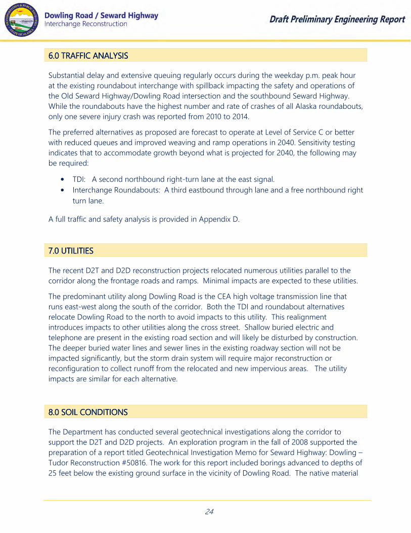
6.0 6.0 6.0 6.0 TRAFFIC ANALYSISTRAFFIC ANALYSISTRAFFIC ANALYSISTRAFFIC ANALYSIS
Substantial delay and extensive queuing regularly occurs during the weekday p.m. peak hour
at the existing roundabout interchange with spillback impacting the safety and operations of
the Old Seward Highway/Dowling Road intersection and the southbound Seward Highway.
While the roundabouts have the highest number and rate of crashes of all Alaska roundabouts,
only one severe injury crash was reported from 2010 to 2014.
The preferred alternatives as proposed are forecast to operate at Level of Service C or better
with reduced queues and improved weaving and ramp operations in 2040. Sensitivity testing
indicates that to accommodate growth beyond what is projected for 2040, the following may
be required:
• TDI: A second northbound right-turn lane at the east signal.
• Interchange Roundabouts: A third eastbound through lane and a free northbound right
turn lane.
A full traffic and safety analysis is provided in Appendix D.
7.0 UTILITIES7.0 UTILITIES7.0 UTILITIES7.0 UTILITIES
The recent D2T and D2D reconstruction projects relocated numerous utilities parallel to the
corridor along the frontage roads and ramps. Minimal impacts are expected to these utilities.
The predominant utility along Dowling Road is the CEA high voltage transmission line that
runs east-west along the south of the corridor. Both the TDI and roundabout alternatives
relocate Dowling Road to the north to avoid impacts to this utility. This realignment
introduces impacts to other utilities along the cross street. Shallow buried electric and
telephone are present in the existing road section and will likely be disturbed by construction.
The deeper buried water lines and sewer lines in the existing roadway section will not be
impacted significantly, but the storm drain system will require major reconstruction or
reconfiguration to collect runoff from the relocated and new impervious areas. The utility
impacts are similar for each alternative.
8.0 SOIL CONDITIONS8.0 SOIL CONDITIONS8.0 SOIL CONDITIONS8.0 SOIL CONDITIONS
The Department has conducted several geotechnical investigations along the corridor to
support the D2T and D2D projects. An exploration program in the fall of 2008 supported the
preparation of a report titled Geotechnical Investigation Memo for Seward Highway: Dowling –
Tudor Reconstruction #50816. The work for this report included borings advanced to depths of
25 feet below the existing ground surface in the vicinity of Dowling Road. The native material

25
is typical of glacial till and is described as being generally silty sandy soils, including the
presence of dense to very dense well graded gravel, cobbles, boulders and silts and clays.
Peat material is known to exist in prevalent amounts along the corridor, particular in the
vicinity of Dowling Road. A layer of peat up to 13 feet thick was encountered in the vicinity of
the existing Dowling Road overcrossing and is assumed to exist north of the current alignment
where the new alignment is proposed. This peat is anticipated to be very soft and saturated,
and will require over excavation or other treatments to prepare the ground prior to road
construction. Medium dense silty sand is expected below the peat and groundwater has been
observed from as deep as 30 feet below ground surface to as shallow as 8 feet below ground
surface. Groundwater could be even shallower based on seasonal variations in the water table.
9.0 RIGHT9.0 RIGHT9.0 RIGHT9.0 RIGHT----OFOFOFOF----WAY REQUIREMENTSWAY REQUIREMENTSWAY REQUIREMENTSWAY REQUIREMENTS
The Department has made a substantial investment in ROW along the corridor as part of the
previous D2T and D2D construction projects, including acquiring interest in over 100 parcels
abutting the frontage roads Brayton Drive and Homer Drive. In anticipation of this interchange
improvement, the Department has also recently acquired parcels along the north side of
Dowling Road, both east and west of the Seward Highway. Both the TDI and Roundabout
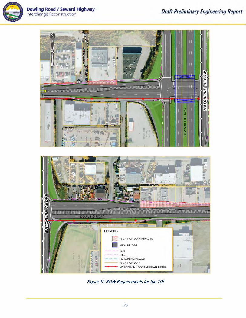
alternatives require additional ROW. These requirements are depicted in Figure 17 and Figure 18
and described on the following pages.
Tight Diamond Tight Diamond Tight Diamond Tight Diamond AlternativeAlternativeAlternativeAlternative: The combination of the mainline embankment walls and closely
spaced ramp terminals of the TDI result in no impacts to ROW along the ramps and frontage
roads for this alternative. ROW impacts are limited to commercial properties on the north side
of Dowling Road.
On the east side of the mainline, parcels bounded by Rowen Street on the west and Burlwood
Street on the east, are impacted as the Dowling Road cross section widens to create space for
the dual left turns under the bridge. These parcels were also identified as being impacted under
the TDI alternative from the DRIAS study. West of the mainline, minor impacts are anticipated to
the commercial properties on either side of Latouche Street as the widened cross section tapers
back to the Dowling Road five lane section.
26
Figure 17: ROW Requirements for the TDIFigure 17: ROW Requirements for the TDIFigure 17: ROW Requirements for the TDIFigure 17: ROW Requirements for the TDI

27
RRRRoundabout Alternativeoundabout Alternativeoundabout Alternativeoundabout Alternative: The
number of parcels impacted
by the roundabout
alternative is very similar to
the TDI but the roundabout
affects different parcels.
Unlike the TDI, ROW is
required for this alternative
along the ramps and
frontage roads. In the
southeast quadrant, a small
impact is anticipated to the
landscaping easement and
existing berm located along
the frontage road at Polaris
school. In the northwest
quadrant, the ramp is being
realigned to provide a more
perpendicular approach to
the cross street. This
requires ROW from the
undeveloped commercial
property fronting Homer
Drive south of 56th Avenue.
The anticipated impacts
along Dowling Road are
limited to a single parcel
east of Latouche Street.
Figure 18: ROW Requirements for the RoundaboutFigure 18: ROW Requirements for the RoundaboutFigure 18: ROW Requirements for the RoundaboutFigure 18: ROW Requirements for the Roundabout

28
10.010.010.010.0 PEDESTRIAN AND BICYCLE FACILITIESPEDESTRIAN AND BICYCLE FACILITIESPEDESTRIAN AND BICYCLE FACILITIESPEDESTRIAN AND BICYCLE FACILITIES
Dowling Road provides a key pedestrian and bicycle route for connections to the Campbell
Creek Trail and as a Seward Highway crossing. A sidepath is provided along the south side of
Dowling Road and a sidewalk is along the north side. While marked crosswalks are provided
through the roundabouts, driver yielding behavior has been observed to be poor, particularly
on the exit lanes. The interchange was identified for crossing improvements in both the
Anchorage Pedestrian Plan and the Anchorage Bicycle Plan.
Both interchange concepts will provide for pedestrian and bicycle paths on the north and
south sides of Dowling Road with marked crossings across ramps and across Dowling Road on
the outside approaches to the intersection. The TDI would accommodate pedestrians and
sidewalk bicyclists through signalized crossings and the roundabout through marked
crosswalks. The key elements to the efficiency, comfort, and safety of these crossings will be
the turning radii and resulting vehicle speeds across the crosswalks. For the TDI, the
pedestrian phasing and signal cycle length, which contributes to crossing delay, will be further
evaluated and refined. To accommodate visually impaired pedestrians, pedestrian activated
beacons will likely be required at the roundabout crossings.
11111111.0 STRUCT.0 STRUCT.0 STRUCT.0 STRUCTURAURAURAURAL SECTION AND PAVEMENT DESIGNL SECTION AND PAVEMENT DESIGNL SECTION AND PAVEMENT DESIGNL SECTION AND PAVEMENT DESIGN
The structural section and pavement design is anticipated to mimic design of the recently
constructed adjacent D2T and D2D projects. The full build structural section of the mainline
consists of 2 inches of Type V Hot Mix Asphalt with hard aggregate over 5 inches of asphalt
treated base, supported by 2 inches of crushed aggregate grading D1 and a minimum of 2 feet
of compacted Type A borrow.
The D2D construction project is currently under construction at the time of this report. That
work has been coordinated with this plan. Because this design project will replace the existing
bridge and construct the full build widened mainline section, the D2D construction work has
been modified. The DOT&PF have eliminated the mainline reconstruction work south of
Dowling Road from the D2D project, deferring that work to this project. This reduces the
required construction dollars on the D2D work, simplifies traffic control for that project, and
eliminates future rework.
Because this portion of the mainline is not being reconstructed with the D2D project, the full
build structural section is required. This differs from the requirements for the mainline north of
Dowling Road. Here, the mainline was fully reconstructed with the D2T project, albeit on a
reduced, narrow cross section. This portion of the mainline will resemble a repaving and
shoulder widening project. The structural section for this work will consist of repaving the
mainline where these improvements fall within the limits of the D2T section, and will fully
reconstruct the section where this project falls outside of the new paving limits.

29
The ramps and frontage roads will be fully reconstructed where their alignment deviates from
the recently reconstructed section. Ramp typical sections are the same as the mainline, where
the frontage roads are constructed with a Type II Hot Mix Asphalt and an asphalt treated base
layer of 2 inches, over 2 inches of crushed aggregate grading D1 and a minimum of 2 feet of
compacted Type A borrow. For this preliminary report, the structural section for the frontage
roads is applied to Dowling Road. This will likely require revision with geotechnical
recommendations that will be developed in design.
These structural sections are shown on the typical section drawings developed for each
alternative contained in Appendix H and Appendix I.
11112222.0 ENVIRONMENTAL COMMITMENTS AND CONSIDERATIONS.0 ENVIRONMENTAL COMMITMENTS AND CONSIDERATIONS.0 ENVIRONMENTAL COMMITMENTS AND CONSIDERATIONS.0 ENVIRONMENTAL COMMITMENTS AND CONSIDERATIONS
The completed Environmental Assessment for the Seward Highway Reconstruction program
studied the environmental impacts associated with an interchange reconstruction at Dowling
Road. Many of the impacts identified in the environmental document were addressed with the
previous D2T and D2D projects. This previous work includes a substantial Area of Potential
Effect (APE) that has been cleared during multiple environmental re-evaluations and the limits
of this improvement fall within that APE.
The governing EA is a broad document that covers improvements from Rabbit Creek Road
north to Tudor Road. It was re-evaluated with the D2T, D2D and 92nd Avenue projects, and it
is currently being re-evaluated yet again with the O2D work currently in design. Instead of re-
evaluating the larger and more complex corridor document for this interchange work, the
environmental strategy is to manage the previous commitments under a simple standalone
environmental document, which is expected to be a Categorical Exclusion.
The impacts associated with either the TDI or roundabout alternative are nominal. Each
alternative satisfies the overall purpose and need of enhancing mobility and improving safety
on the corridor. Providing modern pedestrian and non-motorized accommodations is a
governing commitment that each alternative honors.
Resources that may be effected include wetlands, eagles, and a sensitive school property in the
southeast quadrant of the interchange. The roundabout alternative is expected to have a
minor impact to a landscaping easement abutting the school property, and the realignment of
the southbound off ramp may introduce minor impacts to wetlands on the undeveloped
parcels along the Homer Drive/ramp convergence.
The use of walls to mitigate noise to surrounding businesses and residents was examined twice
with the prior projects. Noise walls did not meet the reasonable and feasible criteria of the
DOT&PF’s noise policy in place at the time of construction and noise walls were not
constructed. A reexamination of the selected build alternative should be conducted to confirm
that the proposed improvements are consistent with the current policy.
30
11113333.0 PUBLIC INVOLVEMENT.0 PUBLIC INVOLVEMENT.0 PUBLIC INVOLVEMENT.0 PUBLIC INVOLVEMENT
The team launched public involvement for the project with a booth at the Anchorage
Transportation Fair on February 8, 2018. The PI work also featured a kick off email notification
containing a survey about different types of interchanges. Other public involvement work to
date includes a public involvement plan, a website, and planning for a public meeting at the
end of June concurrent with release of this draft Preliminary Engineering Report (PER).
Additional events are planned to seek input as project design continues. The final approved
public involvement plan is contained in Appendix F.
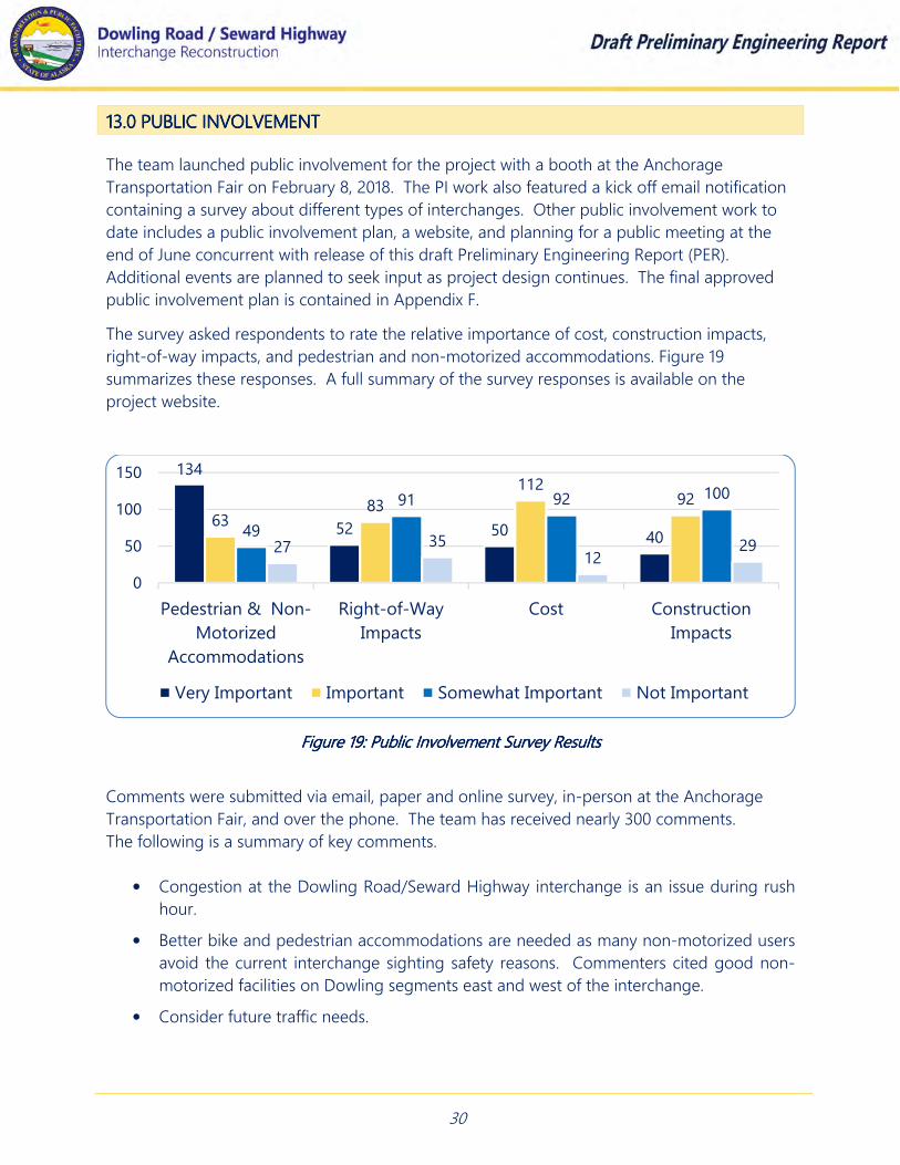
The survey asked respondents to rate the relative importance of cost, construction impacts,
right-of-way impacts, and pedestrian and non-motorized accommodations. Figure 19
summarizes these responses. A full summary of the survey responses is available on the
project website.
Comments were submitted via email, paper and online survey, in-person at the Anchorage
Transportation Fair, and over the phone. The team has received nearly 300 comments.
The following is a summary of key comments.
• Congestion at the Dowling Road/Seward Highway interchange is an issue during rush
hour.
• Better bike and pedestrian accommodations are needed as many non-motorized users
avoid the current interchange sighting safety reasons. Commenters cited good non-
motorized facilities on Dowling segments east and west of the interchange.
• Consider future traffic needs.
134
52 50 4063
83
11292
49
91 92 100
27 3512
29
0
50
100
150
Pedestrian & Non-
Motorized
Accommodations
Right-of-Way
Impacts
Cost Construction
Impacts
Very Important Important Somewhat Important Not Important
FFFFigure 19: Public Involvement Survey Resultsigure 19: Public Involvement Survey Resultsigure 19: Public Involvement Survey Resultsigure 19: Public Involvement Survey Results

31
• Consider enhancing driver education about how roundabouts and other interchanges
work.
• Speeding is a problem with the current roundabout interchange and throughout the
area.
• Commenters support the current design, stating that it works most of the time.
• Better directional signage would be a great help with any interchange selected.
• People driving don’t see or yield to people walking or biking in the crosswalks.
• In a two-lane roundabout, traffic in the outside lane should be going straight or to the
right and the inside lane should be making a forced left, similar to the roundabouts at C
Street and Minnesota.
• Consider showing interchange options in three dimensions or video to enhance the
public’s understanding of how to navigate them.
• Roundabouts, if redesign is chosen, should be larger and accommodate all users—
including trucks and non-motorized users.
• Design for our winter city by considering snow storage, sidewalk/pathway setbacks so
the facilities can be used throughout the year.
• Consider the human factor—how people behave—when designing the location of curb
cuts, light poles, cross walks, push buttons, etc.
11114444.0 CONSTRUCTA.0 CONSTRUCTA.0 CONSTRUCTA.0 CONSTRUCTABILITY CONSIDERATIONSBILITY CONSIDERATIONSBILITY CONSIDERATIONSBILITY CONSIDERATIONS
Constructing a new mainline bridge over Dowling Road while simultaneously keeping mainline
and cross street traffic moving is the most significant and challenging aspect of the project. In
addition to the maintenance of traffic, there are several elements at the existing site that add
to this complexity. These include the presence of the high voltage overhead transmission
main running along Dowling Road, anticipated running sands, deep peat and high
groundwater at the project site.
The DOT&PF held a construction coordination meeting in advance of the planning
worksession to address the overall constructability of the project. The coordination meeting
included representatives from DOT&PF management, and leaders from the construction
section, materials section, bridge design and consultant team design engineers. Minutes from
this meeting are included in Appendix B.
The construction team noted several fundamental design elements needed to successfully
construct the project. Specifically:
32
• Avoiding changes to the profile grade of the mainline or cross street
• Constructing a single span bridge
• Design pile supported bridge foundations
To the extent practical, these elements are represented in the preliminary designs. The
mainline profile is replicated to match the exiting profile grade in the field today. Slight
excavation along the Dowling Road profile is shown in order to provide adequate clearance
underneath the bridge structure. This excavation may be reduced with future design as the
bridge type, girder depths and roadway geometrics are refined.
A single span bridge can be provided for each alternative, and is proposed in these preliminary
designs. The use of a single span provides the opportunity to demolish the existing structure
and construct the new bridge using a “half width” construction technique to maintain traffic.
Under this concept, eliminating roadway shoulders and using median barriers allow for the
northbound and southbound mainline traffic to share one side of the existing bridge while the
other side is demolished and reconstructed. Once half of the new bridge is in place, traffic is
moved to that side while the other side of the structure is completed. This technique allows
for Dowling Road to generally remain open during construction. At the preliminary
engineering level, this appears to be a viable construction methodology, but the structural
implications of a half-width bridge demolition need to be considered in greater detail as the
design progresses. Other less desirable alternatives include mainline detours around the
bridge site and extended closure of Dowling Road, or offsite fabrication and rapid installation
of a non-traditional bridge.
The final major constructability consideration involves building the bridge immediately
adjacent to the CEA high voltage overhead transmission line. While the Dowling Road
alternatives have been thoughtfully laid out to avoid impacts to the line, there are safety
regulations associated with operating bridge cranes in close proximity to these overhead lines.
Generally the crane must be located a distance from the overhead line that is greater than the
height of the crane. This overhead power line and crane conflict was an issue on the recently
constructed West Dowling Road extension project. Despite thoughtful design and permitting,
the Department was required to negotiate with the contractor to temporarily relocate power
poles while in construction.
Benefiting from the West Dowling Road experience, this project has the opportunity to
mitigate these risks during design. Alternative construction techniques to avoid this conflict
may include requiring a single, mid-span crane pick for girder launching to create space
between the line and the crane, or requiring girders to be jacked into place from below,
completely eliminating the use of cranes.

33
15.0 BRIDGE AND MAJOR STRUCTURES15.0 BRIDGE AND MAJOR STRUCTURES15.0 BRIDGE AND MAJOR STRUCTURES15.0 BRIDGE AND MAJOR STRUCTURES
Detailed preliminary bridge designs are included with bridge selection memorandums for each
alternative in Appendix G. Four options were developed for each alternative, including two
single span options and two double span options. The single span options feature shallow
foundations consisting of spread footings on MSE wall fill, while the double span bridge
alternatives feature deeper pile supported foundations.
Three of the four alternatives developed feature deck bulb tee girders with depths ranging
from 3.5 feet to 5.5 feet. These girder depths can provide adequate clearance under the
structure while maintaining the profile grade on the Seward Highway mainline. One
alternative features steel girders, which are approximately 3.5 feet deeper than the deck bulb
tees. The use of the steel girder option requires substantial changes to the Seward Highway
profile grade.
The most cost effective structure features a single span bridge on deck bulb tees with a bridge
length of 145’ and vertical abutment walls. This bridge is the maximum length for this type of
single span bridge. As configured, this bridge can accommodate either alternative, which is
desirable because the structure design life is for 50 years and the project design horizon is
only 20 years. This configuration provides forward compatibility and maximum flexibility in the
future. This bridge was used as the selected bridge type for the preliminary designs. This does
not preclude future use of either two span options if the geotechnical recommendations
require deeper foundations.
These bridge types are common to local contractors, very durable and fast to construct. Their
heavy girders require large cranes to construct, which need to be balanced by the
constructability issues associated with the CEA overhead transmission line. Figure 20 shows a
similar bridge structure at the Minnesota Drive and Raspberry Road interchange.
Figure 20: Single Span Bridge on Deck Bulb Tee GirdersFigure 20: Single Span Bridge on Deck Bulb Tee GirdersFigure 20: Single Span Bridge on Deck Bulb Tee GirdersFigure 20: Single Span Bridge on Deck Bulb Tee Girders (Source: DOT&PF)
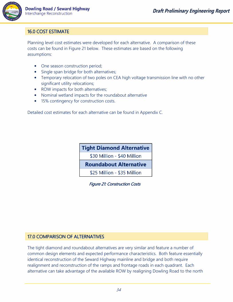
34
11116666.0 COST ESTIMATE.0 COST ESTIMATE.0 COST ESTIMATE.0 COST ESTIMATE
Planning level cost estimates were developed for each alternative. A comparison of these
costs can be found in Figure 21 below. These estimates are based on the following
assumptions:
• One season construction period;
• Single span bridge for both alternatives;
• Temporary relocation of two poles on CEA high voltage transmission line with no other
significant utility relocations;
• ROW impacts for both alternatives;
• Nominal wetland impacts for the roundabout alternative
• 15% contingency for construction costs.
Detailed cost estimates for each alternative can be found in Appendix C.
11117777.0 COMPARISON OF ALTERNATIVES.0 COMPARISON OF ALTERNATIVES.0 COMPARISON OF ALTERNATIVES.0 COMPARISON OF ALTERNATIVES
The tight diamond and roundabout alternatives are very similar and feature a number of
common design elements and expected performance characteristics. Both feature essentially
identical reconstruction of the Seward Highway mainline and bridge and both require
realignment and reconstruction of the ramps and frontage roads in each quadrant. Each
alternative can take advantage of the available ROW by realigning Dowling Road to the north
Figure 21: Construction Figure 21: Construction Figure 21: Construction Figure 21: Construction CostsCostsCostsCosts

35
but both alternatives require additional ROW beyond what is available today. Both can be
designed and constructed to avoid permanent relocation of the CEA overhead transmission
line and each can accommodate pedestrian and bicycle users.
Despite the number of common elements, there are distinct differences between the two.
These include:
• The TDI requires MSE walls which increases the construction cost of this alternative.
• The TDI requires signal coordination with the signals along Dowling Road to optimize
progression along the alignment and for optimal signal spacing. Not only does this
increase the construction cost for this option, but DOT&PF would incur costs to maintain
these signals, increasing maintenance costs.
• Alternatively, the roundabouts can be landscaped with low cost improvements that require
little maintenance.
• The roundabout footprint includes environmental impacts at Polaris school in the
southeast quadrant and the undeveloped commercial property with known wetlands in the
northwest quadrant.
• The roundabout is familiar to the traveling public at this location.
• There are other roundabouts in construction or in design that are used as interchange
ramp terminals on the corridor (Huffman Road, 76th Avenue and 92nd Avenue), further
demonstrating driver familiarity for this interchange type.
• Other signalized diamond interchanges on the corridor (Dimond Boulevard and O’Malley
Road) are currently being redesigned as DDI interchanges and there are no signalized TDI’s
on the corridor.
Figure 22: Comparison Figure 22: Comparison Figure 22: Comparison Figure 22: Comparison GraphicGraphicGraphicGraphic
36
11118888.0 RE.0 RE.0 RE.0 RECOMCOMCOMCOMMMMMENDATIONSENDATIONSENDATIONSENDATIONS
The previous section compares the tight diamond against the roundabout alternative on a
number of project specific criteria. Figure No. 22 demonstrates that both alternatives are
reasonable and technically feasible alternatives that could be selected for the build alternative.
They both fully reconstruct the six lane expanded Seward Highway mainline, completing the link
between the D2T and D2D projects, fulfilling the expanded highway reconstruction set forth in
the project environmental documents. Each is expected to meet the travel demand in the year
2040 and they both feature the exact same Seward Highway bridge, providing for maximum
flexibility in the distant future, beyond the design horizon for this project. With thoughtful
design, both can readily accommodate pedestrians and non-motorized users, and each
alternative requires a similar amount of additional ROW.
The tight diamond has clear advantages in the environmental category, as the footprint
associated with this alternative does not pose impacts to wetlands or the Polaris School in the
southeast quadrant of the interchange. The use of retaining walls along the mainline and the
placement of signalized intersections adds to the upfront construction costs, which are higher
than the roundabout alternative. Additionally, the TDI requires ongoing maintenance of two
signalized intersections. This alternative was previously identified as the preferred build
alternative for this interchange. This PER concurs that a tight diamond alternative is an
acceptable and feasible alternative that could be selected as the build alternative.
The roundabout alternative has several unique advantages and disadvantages when compared to
the TDI. The principal disadvantage is associated with the impacts to wetlands in the northwest
quadrant and impacts to the Polaris School in the southeast quadrant, which would both require
more emphasis on environmental permitting and coordination than the TDI.
These disadvantages are offset by several distinct advantages for this alternative. Specifically, the
spacing of the ramps provide sufficient room such that walls are not required to retain the
Seward Highway mainline embankment. This, combined with the lack of signalized intersections,
results in an improvement that is initially less costly, and does not require long-term maintenance
of signals.
Finally, roundabout terminals exist at the interchange today. A new grade separated crossing of
the Seward Highway with roundabout terminals is currently being constructed just south on the
corridor at 76th Avenue and a new grade separated crossing of the Seward Highway with
roundabout terminals is currently in design and planned for 92nd Avenue. There are no signalized
tight diamonds on the corridor and the roundabout alternative has distinct advantages from the
perspective of corridor consistency and public and agency expectations for this interchange.
Because the roundabout alternative is less expensive to construct, does not require long-term
maintenance of signals, is consistent with other interchange types on the corridor, and meets
both driver and agency expectations for the interchange, it is the Engineer’s recommendation for
the build alternative.
APPENDIX AAPPENDIX AAPPENDIX AAPPENDIX A
Preliminary Design CriteriaPreliminary Design CriteriaPreliminary Design CriteriaPreliminary Design Criteria

APPENDIX BAPPENDIX BAPPENDIX BAPPENDIX B
Worksession Meeting Minutes and PresentationWorksession Meeting Minutes and PresentationWorksession Meeting Minutes and PresentationWorksession Meeting Minutes and Presentation

APPENDIX CAPPENDIX CAPPENDIX CAPPENDIX C
Construction Cost EstimatesConstruction Cost EstimatesConstruction Cost EstimatesConstruction Cost Estimates

APPENDIX APPENDIX APPENDIX APPENDIX DDDD
Preliminary Traffic and Safety ReportPreliminary Traffic and Safety ReportPreliminary Traffic and Safety ReportPreliminary Traffic and Safety Report
APPENDIX APPENDIX APPENDIX APPENDIX EEEE
Roundabout Operations MemorandumRoundabout Operations MemorandumRoundabout Operations MemorandumRoundabout Operations Memorandum

APPENDIX APPENDIX APPENDIX APPENDIX FFFF
Public Involvement PlanPublic Involvement PlanPublic Involvement PlanPublic Involvement Plan

APPENDIX APPENDIX APPENDIX APPENDIX GGGG
Bridge Selection MemorandumBridge Selection MemorandumBridge Selection MemorandumBridge Selection Memorandum

APPENDIX APPENDIX APPENDIX APPENDIX HHHH
Tight Diamond Interchange Alternative PlansTight Diamond Interchange Alternative PlansTight Diamond Interchange Alternative PlansTight Diamond Interchange Alternative Plans

APPENDIX APPENDIX APPENDIX APPENDIX IIII
Roundabout Interchange Alternative PlansRoundabout Interchange Alternative PlansRoundabout Interchange Alternative PlansRoundabout Interchange Alternative Plans


![[PAGE INTENTIONALLY LEFT BLANK]€¦ · inogen, inc. fiscal 2015 annual report. [page intentionally left blank]](https://img.pdfslide.net/doc/110x75/603dd78a05f41851485839e0/page-intentionally-left-blank-inogen-inc-fiscal-2015-annual-report-page-intentionally.jpg)