Embed Size (px)
Citation preview
1
Reprinted with permission of the Hydraulic Institute, www.pumps.org Copyright© 2019 by Turbomachinery Laboratory, Texas A&M Engineering Experiment Station
UNDERSTANDING THE EFFECTS OF SELECTING A PUMP PERFORMANCE TEST ACCEPTANCE GRADES
AUTHOR
This paper was authored by the Hydraulic Institute’s Understanding the Effects of Pump Performance Test Acceptance Grades
committee. The chair of the committee is Al Iseppon, Pentair – Berkeley, and the Vice-chair of the committee is Rodney Mrkvicka,
Smith & Loveless, Inc.
ABSTRACT
There are good reasons for requiring the tightest test acceptance tolerances. That is why they are listed in industry accepted pump testing
standards, ANSI/HI 14.6, ANSI/HI 11.6 and ISO 9906. There are also applications where selection of the more stringent grade is not
necessary to insure the pump will operate satisfactorily in the process. The user or specifier should evaluate all grades available and
make an informed decision selecting the correct grade for their application, delivery requirements and cost targets. This paper briefly
highlights the importance of selection of proper acceptance grade for pump performance testing. There are many reasons for selecting
a specific acceptance grade when requesting hydraulic performance tests. Some are specified by the user based on applications and
industry standards, some are mandated by contract and some are “because we’ve always done it this way”. In most cases there is plenty
of logic in the selection of the grade and how it is applied. However, the impact on the cost and delivery of that decision is not always
clearly understood. Application of the tightest tolerances will require more work by the manufacturer which will typically extend the
delivery date and increase the cost to accommodate the extra effort to insure the pumps comply. Less stringent grades will require less
work and shorten the time to manufacture and test. The paper will present the acceptance grades available and the tradeoffs of specifying
each grade.
INTRODUCTION
Pump purchasers and specifiers may require pumps be hydraulically performance tested prior to shipment to verify the required
performance parameters. This testing is normally performed at the manufacturer’s facility, and the performance parameters are
confirmed by conducting a hydraulic performance test on the actual pump unit. This hydraulic testing confirms the pump’s rate of flow,
head generated and can include power consumed by the pump unit. The pump is normally tested at various points across its operating
curve, including the defined application duty or guarantee point, shut off head, and a flow rate beyond the guarantee point.
A hydraulic performance test provides actual pump operating data for that specific pump unit, including the installed driver if applicable.
Since the pump test includes measurements of hydraulic rate of flow, head generated, and consumed power measured by various
instruments, the actual pump test results will contain deviations from the predicted values. In addition, because of manufacturing
variation, no two pumps will perform exactly alike. Depending on the application and the service required, the amount of deviation
allowed can vary. This is defined as the tolerance band. The end user or consultant needs to specify the tolerance band prior to the
testing so that the pump manufacturer can properly fabricate and assemble the pump system and conduct the testing to achieve results
within the required tolerance.
Selecting the tolerance band involves many factors: the pump's application, sensitivity of the system, regulatory requirements, pump
efficiency, and the importance of the pump in its specified service. The tolerance band selected can also have implications on the cost
of testing and the delivery schedule.
Many end users or consultants do not understand the testing differences or the effects of selecting a specific acceptance grade. In some
cases, the tolerance selection may not match the intended service or can cause the cost of the pump to increase significantly. A good
understanding of the acceptance grades and their effects on the pump unit itself is necessary to ensure the proper selection for the service
and the best value for the end user. This document intends to identify these differences and explain the effects and considerations to be
made when selecting a certain acceptance grade.

2
Reprinted with permission of the Hydraulic Institute, www.pumps.org Copyright© 2019 by Turbomachinery Laboratory, Texas A&M Engineering Experiment Station
PERFORMANCE TESTING AND GURANTEES
Three complementary industry standards have been published to assist with standardizing hydraulic pump performance test procedures
and acceptance grades. These are:
1. Hydraulic Institute ANSI/HI 11.6 (2017) Standard for Rotodynamic Submersible Pumps for Hydraulic Performance,
Hydrostatic Pressure, Mechanical and Electrical Acceptance Tests,
2. Hydraulic Institute ANSI/HI 14.6 (2016) Standard for Rotodynamic Pumps for Hydraulic Performance Acceptance Tests, and
3. ISO 9906 (2012) Rotodynamic Pumps – Hydraulic Performance Acceptance Test – Grades 1, 2, and 3.
Included in each standard are multiple performance acceptance grades. What differs between these grades is the tolerance band that can
be applied to the test data to determine if a pump successfully meets the end user’s requirements. Some acceptance grades have unilateral
(U) tolerance bands and some have bilateral (B) tolerance. The E designation is a special application with a unilateral efficiency
tolerance. Table 1 shows the acceptance grade table from ANSI/HI 14.6.
Table 1 — ANSI/HI 14.6 performance acceptance grade table
a Efficiency is a calculated value that is dependent on pump power input and, therefore, either minimum efficiency or maximum pump
power input at the guarantee point can be specified, but not both.
Any acceptance test conducted per these industry standards focuses on meeting performance at a given duty point, also referred to as
the guarantee point. The guarantee point is the user’s specified head and flow rate normally used to select the pump. The user may also
specify a requirement for measured power or calculated efficiency related to the same guarantee point. Additional operating points may
be specified along with the guarantee point and will be evaluated at the 3B level.
The purchaser/specifier/end user may select the acceptance grade that best meets their requirements for the specific application. Each
grade has unique advantages and disadvantages that should be understood before a final acceptance grade is selected.
ACCEPTANCE GRADE SELECTION CONSIDERATIONS
Selection of an acceptance grade determines the performance tolerance of a pump agreed upon by the user and the manufacturer. The
acceptance grade chosen should be based on the requirements of the user’s application.
The acceptance grade selected can also affect the cost of the pump. It is necessary to maintain tighter manufacturing tolerances and test
procedure controls to meet the more stringent acceptance grades. Tighter tolerances and controls will require additional time to
manufacture, finish and test the pump, resulting in additional costs and extended delivery times.
Reasons to request a more restrictive acceptance grade for a hydraulic performance test include the following:
Critical applications that require precise pump performance.
Ensuring a pump provides a minimum rate of flow needed to meet system or regulatory requirements. For these applications,
a unilateral acceptance grade would be applicable.
A Grade 1 tolerance may be needed for processes that require more exact pump performance controls, or when proper system
operation requires that the performance of several pumps be matched. For example, pumps in parallel operation are more easily
controlled if their performance curves are similar.

3
Reprinted with permission of the Hydraulic Institute, www.pumps.org Copyright© 2019 by Turbomachinery Laboratory, Texas A&M Engineering Experiment Station
The shape of the pump curve and the system curves are such that a small change in one has a significant impact on the other.
This is a system characteristic that can have significant impact on pump performance in the application and can influence the
decision on how exacting the performance must be. See example 2 below.
Pumps applied in a system that has a relatively flat curve or mostly static head benefit from tighter control of the guarantee
point
More restrictive limits on pump performance could help avoid the use of large safety margins and overdesign of associated
equipment. For example, controlling the pump maximum head could lower the pressure rating required for large tanks and
pipelines.
A more restrictive Grade 1U acceptance grade applied with the added specification of a power or efficiency tolerance could
limit the absorbed power and therefore the associated operating costs. This cost savings could be significant, especially for high
power pumps running in continuous operation.
Figure 1 shows a general diagram indicating the acceptance levels and the typical applications.
Figure 1 — Testing acceptance grades and typical guidance notes
For processes where greater performance variation is acceptable but the user must still know the true operating range, a certified test
with a wider acceptance tolerance such as Grade 3 can be specified. Other systems will fall somewhere between these examples.
Serious thought must be given to selecting the appropriate acceptance grade. A wider tolerance opens the possibility to accept a
smaller pump that will cost less and reduce energy use but still be compliant and adequate for the service intended. In cases where a
selection bridges the gap in motor sizes, a wider acceptance grade may allow the use of the smaller motor, again reducing cost and
potentially saving energy.
The same situation can occur by selecting a bilateral tolerance as opposed to a unilateral tolerance. The bilateral tolerance opens the
possibility to use a slightly smaller pump and motor and reduce cost. This may also open the options when the selection falls between
standard motor sizes. When selecting a tolerance grade, the user must decide what level of precision is needed and understand the
implications considering the potential higher cost and longer lead times.

4
Reprinted with permission of the Hydraulic Institute, www.pumps.org Copyright© 2019 by Turbomachinery Laboratory, Texas A&M Engineering Experiment Station
TESTING ACCEPTANCE GRADE EFFECTS ON COST AND DELIVERY
Some degree of acceptance tolerance must be applied to all measurable parameters. Variations in hydraulic performance are the result
of manufacturing tolerances, testing instrument fluctuations and accuracy, driver (motor) variation, and the inherent instabilities in the
pumped media near the pump suction and discharge. The magnitude of these variations will vary directly with the degree of precision
applied to manufacturing processes, the test equipment, and test procedures. The higher the precision used in manufacturing and testing,
the smaller the expected variations in test results. Refer to ANSI/HI 14.6 Appendix C for more details.
Complying with acceptance grades with the tightest and/or unilateral tolerances (especially when efficiency or power is included) may
require castings with smoother surface finish and tighter controlled internal dimensions clearances. Examples of these processes include
vane re-profiling, surface polishing, and special surface coatings. Any or all of these may not be standard practice in the production of
a part or pump assembly, and can result in additional cost and extended delivery times. Unilateral acceptance grades (1U, and 2U as
well as 1E for efficiency) may also require additional enhancements to a pump after initial testing. The pump will then be tested a second
time to confirm the enhancements were successful.
Specifying less restrictive tolerance bands, such as Grades 2 and 3, can reduce or eliminate the need for additional manufacturing
operations as standard components can be utilized. This limits the impact on cost and delivery time.
EFFICIENCY OR POWER ACCEPTANCE REQUIREMENT CONSIDERATIONS
When a user specifies pump efficiency or pump power requirements, the manufacturer must have the correct equipment to accurately
measure the pump-absorbed power as defined in any of the three testing standards referenced above. .
One method requiring torque measurement typically involves the manufacturer using a custom baseplate that allows the torque-meter
to be coupled directly between the motor and pump shafts. The addition of couplings, a custom base plate, and the additional setup time
involved to ensure accurate alignment adds cost to the test setup. It will also increase the overall time taken to test the pump.
A second method requires the manufacturer to measure power input to a suitably sized calibrated motor. To ensure complete motor
coverage, the manufacturer must maintain a suitable inventory of adequately sized calibrated motors, which can significantly increase
the cost of testing.
ACCEPTANCE GRADE IMPACTS
Table 2 reflects the relative impact of acceptance grade selections due to the wide variety of manufacturing processes used to produce
the numerous rotodynamic pumps covered by these standards. The magnitude of the actual impacts listed in this table will vary based
upon numerous factors including pump size, pump type, and manufacturing processes. In addition, the actual impacts may differ for
each manufacturer.
Table 2 also indicates the relative impact of the various testing grades. Items with 0 have no impact. The larger the number of characters
($ or +) indicates more cost or greater lead time, respectively, potentially required to perform the testing to that level.
Without efficiency or power specified Acceptance grade
No test specified 1B 1E 1U 2B 2U 3B
Product Cost - $ $ $$ 0 0 0
Testing Cost 0 $$$ $$$ $$$ $$ $$ $
Delivery Time 0 +++ +++ +++ ++ ++ +
With efficiency or power guaranteed*
Acceptance grade
No test specified 1B 1E 1U 2B 2U 3B
Product Cost 0 $$$ $$$$ $$$$ $$ $$$ $
Testing Cost 0 $$$ $$$$ $$$$ $$ $$$ $
Delivery Time 0 +++ ++++ ++++ ++ +++ +
Table 2 — Testing acceptance grade impact
*Efficiency is a calculated value that is dependent on pump power input and, therefore, either minimum efficiency or maximum pump
power input at the guarantee point can be specified, but not both.

5
Reprinted with permission of the Hydraulic Institute, www.pumps.org Copyright© 2019 by Turbomachinery Laboratory, Texas A&M Engineering Experiment Station
IMPACT ON ENERGY USAGE
The acceptance grades have an option to include pump power or efficiency at the guarantee point. Unlike the head and flow performance
tolerances, there is no maximum limit on efficiency. Instead, a low limit is established based on a percent of the guaranteed efficiency.
The most stringent grades allow no negative tolerance on efficiency, while the least stringent can allow a reduction of several percent.
Note that the tolerance is a percent of the guaranteed efficiency, and not the number of percentage points less.
An effect of selecting a less restrictive acceptance grade such as Grade 2 or 3 is the potential use of more energy with the greater
allowable positive tolerances above the guarantee point’s head or rate of flow. This is illustrated in the Figure 2 where the graph indicates
the scale of potential energy versus the testing grade selected. An increase in the energy usage for all unilateral acceptance grades will
occur as the pump will be selected to exceed design requirements and in doing so will require more energy to meet the higher demand.
Figure 2 indicates the relative level for energy consumption above the nominal amount of energy needed based on selected testing
acceptance grades.
Figure 2 — Testing acceptance grade effect on power consumption
Figure 2 shows that specifying a less stringent testing tolerance such as Grade 2 or 3 could lead to the manufacturer providing a larger
motor that will use more energy since there is a greater allowable positive tolerance. For some applications, the pump may be supplying
more head or rate of flow than specified. This may require the discharge to be throttled or excess flow to be diverted. In this case, the
pump system will not be operating with optimal efficiency.
Figure 3 indicates a general scale of the possible energy efficiency reduction versus the testing acceptance grade chosen. Specifying a
positive unilateral test acceptance grade may be the best way to maximize the system’s efficiency when a pumping system can effectively
utilize the extra head or rate of flow produced by the pump(s), or when a system has to meet specific minimum pumping levels for
compliance requirements.
0
2
4
6
8
10
12
14
16
18
1B 1E 1U 2B 2U 3BAd
dit
ion
al
en
erg
y c
on
su
mp
tio
n -
%
Acceptance grade
Possible Additional Energy Consumption Due to Tolerance Grade

6
Reprinted with permission of the Hydraulic Institute, www.pumps.org Copyright© 2019 by Turbomachinery Laboratory, Texas A&M Engineering Experiment Station
Figure 3 — Impacts on pump efficiency based on testing acceptance band
As shown in Figure 3, the tighter Grade 1 test acceptance levels minimize the negative efficiency impact on the pump and still meet the
specified efficiency rating.
For pumps that operate continuously or with extended duty cycles, having a pump perform at its optimum efficiency can provide a
significant energy cost savings during the pump’s lifecycle. To ensure the pump is operating at its optimum efficiency at the duty point,
a more stringent test tolerance may be required. However, requesting a more stringent efficiency tolerance may also increase cost and
extend the delivery time for the same reasons that impact cost and delivery when a tighter acceptance grade is applied to a pump’s head
and rate of flow performance.
TEST ACCEPTANCE GRADE SELECTION EXAMPLE #1
Published curves are nominal performance expectations for a given pump and typically include a bilateral tolerance.
For example, if a pump was marketed for sale in an application where the acceptable performance Grade 2B is the market standard, the
published curve (shown in Figure 4 as the solid blue curve) will likely represent an average of historical performance of similar units.
The dashed curves above and below the blue curve characterize the pump’s performance that would meet the 2B criteria.
7
Reprinted with permission of the Hydraulic Institute, www.pumps.org Copyright© 2019 by Turbomachinery Laboratory, Texas A&M Engineering Experiment Station
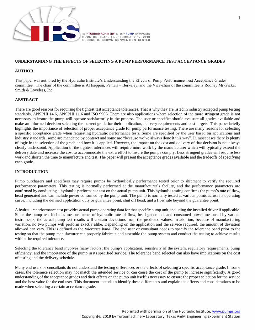
Figure 4 — Pump curve showing a 2B tolerance band
Making a selection based on this general market curve, which was intended to have a 2B tolerance for an application that requires a 1U
tolerance pump, will likely require adjustment from the manufacturer (as shown with the orange dashed curve on Figure 5) to bring the
anticipated performance variation above the requested guarantee point. In the process of raising the tolerance band on basic hydraulic
performance, the power required could increase due to the increase in expected rate of flow and head to be within the tolerance band of
the requested performance. In this instance, when aiming for the midpoint above the 2B curve (blue curve) for a 1U requirement (orange
curve), the power increases substantially to make a non-overloading 100 HP curve now a 125 HP non-overloading curve. Figure 6
provides an example of driver power requirements for a pump.
Figure 5 — Example pump curve with adjusted performance curve
Hea
d
Rate of flow
Hea
d
Rate of flow

8
Reprinted with permission of the Hydraulic Institute, www.pumps.org Copyright© 2019 by Turbomachinery Laboratory, Texas A&M Engineering Experiment Station
Figure 6 — Driver power requirements for pump example
TEST ACCEPTANCE GRADE SELECTION EXAMPLE #2
The next example compares the effects of different system curve shapes on expected performance ranges. It also shows that the
magnitude of allowable rate of flow and head should be considered. Figure 7 shows a small pump manufactured for a tolerance band
of 3B, where its intended use does not require precise flow control. The solid blue curve represents the published pump curve. The
blue dashed lines represent the 3B tolerance band for which it was designed. The grey dashed lines represent a tighter tolerance band
of 1B. Two different system curves are also plotted – the steeper System Curve 2 having more friction head than the System Curve 1.
Figure 7 — Pump performance curve example indicating tolerance bands and system curves
0
20
40
60
80
100
120
0 2000 4000 6000 8000 10000
Po
wer
Capacity
Example 2
Q (US GPM)0 60 120 180 240 300 360 420
Q (m3/h)0 20 40 60 80 100
H(f
t)
0
5
10
15
20
25
30
35
40
45
50
55
60
H (m)0
2
4
6
8
10
12
14
16
18
Blue = 2B / Red = 1U
System 1
System 2
Published curve
3B tolerance band
1B tolerance band

9
Reprinted with permission of the Hydraulic Institute, www.pumps.org Copyright© 2019 by Turbomachinery Laboratory, Texas A&M Engineering Experiment Station
While the flow and head range when the pump is operating with the System Curve 1 is larger than the range when operating with
system Curve 2, the magnitude of the ranges should be considered when deciding on the appropriate acceptance grade as illustrated in
Table 3 and Table 4.
Metric Units:
The design condition is 50 m3/h @ 8.3 m with pump input power of 2.5 kW.
Tolerance band System Curve 1 System Curve 2
Flow range (m3/h) Head range (m) Flow range (m3/h) Head range (m)
3B 45 to 54 8.1 to 8.5 47 to 52 8.0 to 8.7
1B 48 to 52 8.3 to 8.4 49 to 51 8.2 to 8.5
Maximum difference
between 1B and 3B 3 m3/h 0.2 m 2 m3/h 0.2 m
Table 3 — Metric unit example
US Customary Units:
The design condition is 220 gpm @ 27.3 ft with a BHP of 3.3 hp.
Tolerance band System Curve 1 System Curve 2
Flow range (gpm) Head range (ft) Flow range (gpm) Head range (ft)
3B 200 to 238 26.7 to 27.8 209 to 230 26.1 to 28.4
1B 213 to 228 27.1 to 27.5 215 to 225 26.8 to 27.9
Maximum difference
between 1B and 3B 13 gpm 0.4 ft 6 gpm 0.7 ft
Table 4 US customary unit example
The pump will likely require rework to meet the 1B tolerance because it is designed to a 3B tolerance. This may result in a delivery
time of weeks rather than days. It may also add to the cost of the pump. The pump system designer should consider if the potential 3
m3/h or 0.2 m (13 gpm or 0.7 ft.) difference in tolerance bands merits the additional time and money for the application.
If the pump is specified with a power tolerance, there is also a small difference in potential power absorbed if manufactured to a 1B
tolerance rather than a 3B tolerance. The 3B tolerance allows a BHP up to 2.7 kW (3.6 HP) while the 1B tolerance allows only up to
2.6 kW (3.43 HP) amounting to only a 0.12 kW (0.17 HP) difference for this small pump. Assuming a cost of 0.13 € per kWh and
even if run continuously, this an energy savings of only 136 € per year. Likewise, assuming a cost of $0.05 per kWh and even if run
continuously, this an energy savings of only $54 per year.
TEST ACCEPTANCE GRADE SELECTION EXAMPLE #3
Typical Performance Curves versus Test Grade and Acceptance Grade
The curves in this example were developed to demonstrate how a pump manufacturer might vary the submittal curve depending on the
customer’s specification for a testing and acceptance grade.
Grade 1 Testing
All Grade 1 testing will have the same tolerance band width on rate of flow and the allowable range for the head. There are two bilateral
tolerance ranges and one unilateral tolerance ranges detailed for Grade 1 testing.
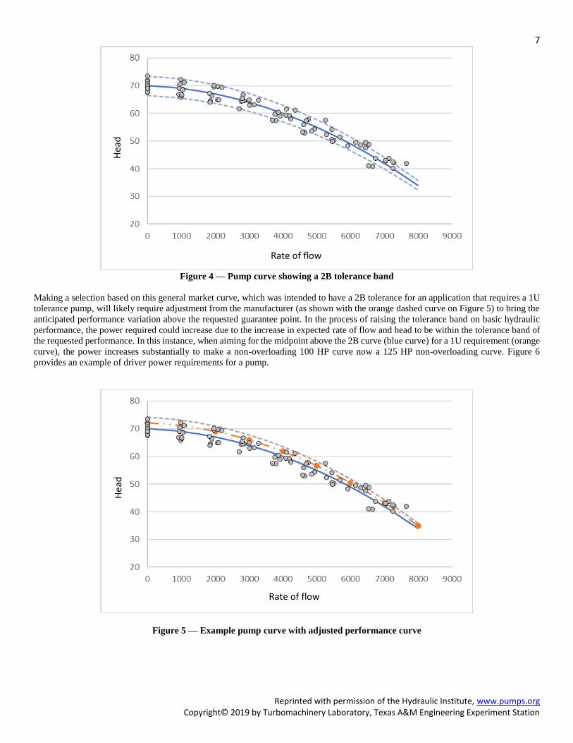
Both the 1B and 1E acceptance grades shown in Figures 8 and 9 have the same bilateral acceptance on rate of flow and head; however,
the 1B allows a -3% tolerance on the optionally guaranteed efficiency. Often this is reflected in the efficiency curve that the pump
manufacturer produces for these two grades.
10
Reprinted with permission of the Hydraulic Institute, www.pumps.org Copyright© 2019 by Turbomachinery Laboratory, Texas A&M Engineering Experiment Station
The 1U acceptance grade shown in Figure 10, like the 1E acceptance grade, does not allow any negative tolerance on the optionally
guaranteed efficiency. Since all rate of flow and head guarantees are based on no negative tolerance being allowed, the pump
manufacturer will typically use a slightly larger impeller diameter to ensure that the unilateral performance guarantees are met. The
larger impeller diameter will require additional power, which typically appears on the submittal curve.
Figure 10 — 1U Acceptance grade
When an optional power guarantee is specified by the customer, the 1U curve typically will show a higher power draw to reflect the
additional power required to cover the additional rate of flow and head in the unilateral acceptance grade.
Grade 2 Testing
All Grade 2 testing will have the same tolerance band width on rate of flow and the allowable range for the head. There is only one
bilateral tolerance range and one unilateral tolerance range detailed for Grade 2 testing. See
Figures 11 and 12. Both the 2B and the 2U acceptance grades allow a -5% tolerance on the optionally guaranteed efficiency.
Figure 8 — 1B Acceptance grade Figure 9 — 1E Acceptance grade

11
Reprinted with permission of the Hydraulic Institute, www.pumps.org Copyright© 2019 by Turbomachinery Laboratory, Texas A&M Engineering Experiment Station
When the optional power guarantee is specified by the customer, the 2U curve typically will show a higher power draw to reflect the
additional power required to cover the additional rate of flow and head minimums for the unilateral acceptance grade.
Grade 3 Testing
Grade 3 testing has the most liberal rate of flow and head acceptance grade as shown in Figure 13. The 3B bilateral acceptance grade
is the only option for Grade 3 testing. The 3B acceptance grade allows a -7% tolerance on the optionally guaranteed efficiency, which
is often reflected on the efficiency curve that the pump manufacturer produces for this grade.
Figure 11 — 2B Acceptance
grade
Figure 12 — 2U Acceptance
grade
Figure 13 — 3B Acceptance grade
12
Reprinted with permission of the Hydraulic Institute, www.pumps.org Copyright© 2019 by Turbomachinery Laboratory, Texas A&M Engineering Experiment Station
CONCLUSIONS
This paper highlights the importance of selecting the appropriate acceptance grade for pump performance testing to satisfy
the needs of its intended service. There are many reasons for selecting a specific acceptance grade when requesting hydraulic
performance tests. Some are specified by the user based on applications and industry standards, some are mandated by
contract and some are “because we’ve always done it this way.” In most cases there is plenty of logic in the selection of the
grade and how it is applied. However, the impact on the cost and delivery of that decision is not always clearly understood.
Application of the tightest tolerances will require additional work by the manufacturer, entail additional costs and require
extra lead time. Less stringent testing grades can potentially reduce the manufacturing and testing schedules. There are good
reasons for requiring the tightest tolerances and that is why they are listed in ANSI/HI 14.6, 11.6, and ISO 9906. There are
also applications where selection of the more stringent acceptance grade is not necessary to ensure the pump will operate
satisfactorily in the process. The user or specifier should evaluate all grades available and make an informed decision
selecting the appropriate grade for their application, delivery requirements and cost targets.
To purchase any of the referenced standards, please contact Hydraulic Institute at www.pumps.org or ISO at www.iso.org .
REFERENCES
Hydraulic Institute, 2019, Understanding the Effects of Selecting a Pump Performance Test Acceptance Grade
Hydraulic Institute, 2016, ANSI/HI 14.6 Rotodynamic pumps for hydraulic performance acceptance tests
Hydraulic Institute, 2017, ANSI/HI 11.6 Rotodynamic submersible pumps for hydraulic performance, hydrostatic, pressure,
mechanical and electrical acceptance tests.
International Organization for Standardization, 2012, ISO 9906 -- Rotodynamic pumps – Hydraulic performance acceptance
tests – Grades 1, 2 and 3
ACKOWLEDGEMENTS
This paper was writing by a Hydraulic Institute Committee following the consensus process. This Hydraulic Institute White
Paper was produced, and approved by a working committee that volunteered their time to meet many times to facilitate its
development. At the time the White Paper was approved, the committee had the following members:
Chair – Al Iseppon, Pentair – Berkeley
Vice-chair – Rodney Mrkvicka, Smith & Loveless, Inc.
Committee member Company
Timothy Albers Nidec Motor Corporation
Julie Ballard KSB, Inc.
Michael Coussens Peerless Pump Company
Frank Ennenbach Sulzer Pumps Ltd.
Mark Heiser Xylem Inc. - Applied Water Systems
Michael Jan Grundfos Water Utility
Alexander Moser Patterson Pump Company
Paul Moulton AECOM
Michael Mueller Flowserve Corporation
Alessandro Nicchio Weir Gabbioneta srl
Scott Race Weir Minerals North America
Craig Redmond Gorman-Rupp, Mansfield Division
Arnold Sdano Pentair - Fairbanks Nijhuis
Jerry Szofer Grundfos Water Utility
Jamie Watkins Crane Pumps & Systems, Inc.

13
Reprinted with permission of the Hydraulic Institute, www.pumps.org Copyright© 2019 by Turbomachinery Laboratory, Texas A&M Engineering Experiment Station
Special Acknowledgements – Peer Review
Several independent experts in the industry review and evaluate committee drafts. They conducted a thorough review of the
material ensuring the document met the intended goal established by the committee and provided accurate, coordinated, and
relevant information to the reader. Their work is extremely valuable and the committee thanks all of them for their time and
efforts.
Steven Fehniger CDM Smith – Water Service Group
Randal Ferman ekwestrel corp.
Mike Zappone Carollo Engineers
Lastly acknowledgement is given to the Hydraulic Institute for making the content of the paper available in support of its
mission to advance the pump manufacturing industry.