Embed Size (px)
Citation preview
8/3/2019 This Simpl1
http://slidepdf.com/reader/full/this-simpl1 1/7
➢INTRODUCTIONThis simple, economical and versatile circuit switches on the motor pump
when water in the overhead tank falls below the lowest level and turns it ‘off’
when the tank is full. It is the circuit which will be used in house water tank,
water tanks of buildings. It is a fully automatic circuit, if someone used this
circuit then there is no need of fill the water tank daily, switch on/off the
motor daily The water-level controller circuit is built around IC 555 (IC2) to
monitor the water level in the overhead tank and ‘on’/‘off’ status of the motor
through the inverter and driver circuits. The transistor switch circuitry
monitors the flow of water.
➢ COMPONENTS .
Transformer :We used step down transformer in our project.
This transformer(X1) steps down the 230V of AC supply to 12V AC.
Thus the number of turns in the secondary winding is less then the
number of turns in primary winding. Current rating in secondary coil
is 300 mA.
Diodes : Here we have used a bridge of four diodes
D1,D2,D3,D4. All these are 1N4007. Diode acts as a switch. When
the positive side of the battery is connected to the p side of thediode then it act as a closed switch but when the positive terminal
is connected to the n side of the diode then it acts as a open switch.
This diode bridge acts as rectifier and converts AC voltage to DC
voltage.
Diode D5 is called freewheeling diode. It is
1N4007. It *****
Another diode used in this circuit is LED
i.e. Light Emitting Diode.it is connected between*****
Resistors : Total five resistors are used-R1,R2,R3,R4,R5.
• R1(10 Ohms) is the current limiting resistor. It carries high
current, so its wattage is high******
(0.5 Watt).• R2 and R3 both are 1 MegaOhms.
8/3/2019 This Simpl1
http://slidepdf.com/reader/full/this-simpl1 2/7
• R4 and R5 both are 1 KiloOhms.
Capacitors : There are six capacitors in the circuit.
• The ripples in the DC voltage from diode bridge are
removed by the filter capacitor C1(1000 MicroFarad, 25Volt).
• C2 and C3 both are 0.1 MicroFarad,*****Watt. They act as
noise filtering capacitors.
• C4 and C6 both are 1 MicroFarad,25 Volt. C5 is 0.01
MicroFarad,***** watt. These three capacitors filter noise.
IC 7812 :
Power Supply : Power supply is obtained through step-down
transformer X1, diodes D1 through D4, capacitor C1, series current-
limiting resistor R1, regulator IC1, and noise-filtering capacitors C2 and
C3.
Transistors :Here we have used two transistors in the circuit- T1(BC548),T2(SL100). The datasheets of these two transistors are
given.
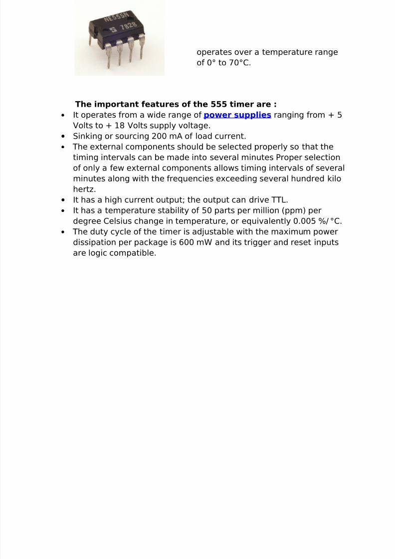
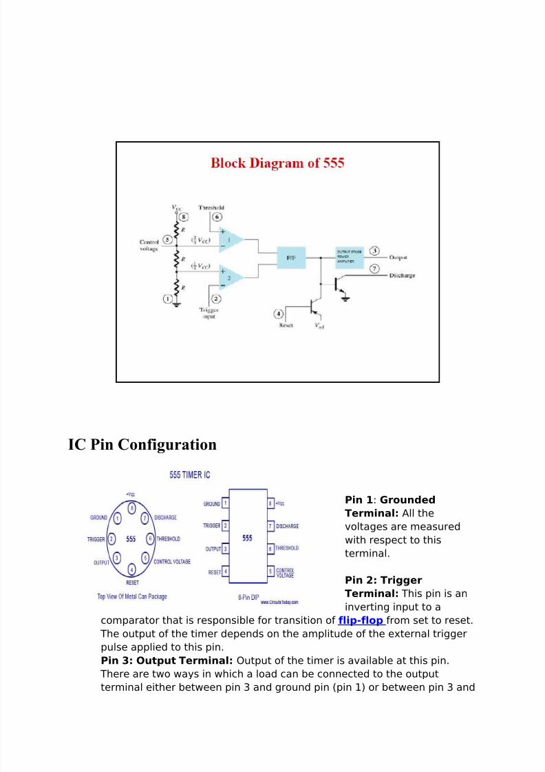
555 Timer : One of the most versatile linear ICs is the 555
timer which was first introduced in early 1970 by Signetic
Corporation giving the name as SE/NE 555 timer. This IC is a
monolithic timing circuit that can produce accurate and highly
stable time delays or oscillation. Like other commonly used op-amps, this IC is also very much reliable, easy to use and cheaper in
cost. It has a variety of applications including monostable and
astable multivibrators, dc-dc converters, digital logic probes,
waveform generators, analog frequency meters and
tachometers, temperature measurement and control devices,
voltage regulators etc. The timer basically operates in one of the
two modes either as a monostable (one-shot) multivibrator or as an
astable (free-running) multivibrator. The SE 555 is designed for theoperating temperature range from – 55°C to 125° while the NE 555
8/3/2019 This Simpl1
http://slidepdf.com/reader/full/this-simpl1 3/7
operates over a temperature range
of 0° to 70°C.
The important features of the 555 timer are :
• It operates from a wide range of power supplies ranging from + 5
Volts to + 18 Volts supply voltage.
• Sinking or sourcing 200 mA of load current.
• The external components should be selected properly so that the
timing intervals can be made into several minutes Proper selection
of only a few external components allows timing intervals of several
minutes along with the frequencies exceeding several hundred kilo
hertz.
• It has a high current output; the output can drive TTL.
• It has a temperature stability of 50 parts per million (ppm) per
degree Celsius change in temperature, or equivalently 0.005 %/ °C.
• The duty cycle of the timer is adjustable with the maximum power
dissipation per package is 600 mW and its trigger and reset inputs
are logic compatible.
8/3/2019 This Simpl1
http://slidepdf.com/reader/full/this-simpl1 4/7
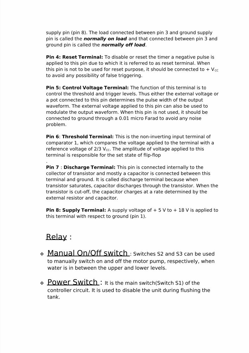
IC Pin Configuration
Pin 1: Grounded
Terminal: All the
voltages are measured
with respect to thisterminal.
Pin 2: Trigger
Terminal: This pin is an
inverting input to a
comparator that is responsible for transition of flip-flop from set to reset.
The output of the timer depends on the amplitude of the external trigger
pulse applied to this pin.
Pin 3: Output Terminal: Output of the timer is available at this pin.
There are two ways in which a load can be connected to the outputterminal either between pin 3 and ground pin (pin 1) or between pin 3 and
8/3/2019 This Simpl1
http://slidepdf.com/reader/full/this-simpl1 5/7
8/3/2019 This Simpl1
http://slidepdf.com/reader/full/this-simpl1 6/7
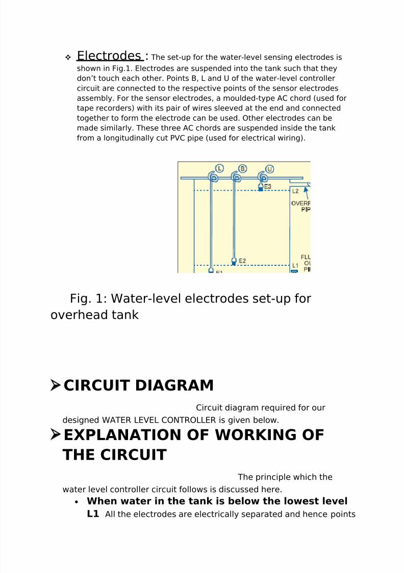
Electrodes : The set-up for the water-level sensing electrodes is
shown in Fig.1. Electrodes are suspended into the tank such that they
don’t touch each other. Points B, L and U of the water-level controller
circuit are connected to the respective points of the sensor electrodes
assembly. For the sensor electrodes, a moulded-type AC chord (used fortape recorders) with its pair of wires sleeved at the end and connected
together to form the electrode can be used. Other electrodes can be
made similarly. These three AC chords are suspended inside the tank
from a longitudinally cut PVC pipe (used for electrical wiring).
Fig. 1: Water-level electrodes set-up foroverhead tank
➢CIRCUIT DIAGRAM
Circuit diagram required for our
designed WATER LEVEL CONTROLLER is given below.
➢EXPLANATION OF WORKING OF
THE CIRCUIT
The principle which the
water level controller circuit follows is discussed here.
• When water in the tank is below the lowest levelL1 All the electrodes are electrically separated and hence points
8/3/2019 This Simpl1
http://slidepdf.com/reader/full/this-simpl1 7/7