Embed Size (px)
Citation preview

Relion. Thinking beyond the box.
Designed to seamlessly consolidate functions, Relion relays are smarter, more flexible and more adaptable. Easy to integrate and with an extensive function library, the Relion family of protection and control delivers advanced functionality and improved performance.
This webinar brought to you by the Relion® product family Advanced protection and control IEDs from ABB

ABB is pleased to provide you with technical information regarding
protective relays. The material included is not intended to be a complete
presentation of all potential problems and solutions related to this topic.
The content is generic and may not be applicable for circumstances or
equipment at any specific facility. By participating in ABB's web-based
Protective Relay School, you agree that ABB is providing this information
to you on an informational basis only and makes no warranties,
representations or guarantees as to the efficacy or commercial utility of
the information for any specific application or purpose, and ABB is not
responsible for any action taken in reliance on the information contained
herein. ABB consultants and service representatives are available to
study specific operations and make recommendations on improving
safety, efficiency and profitability. Contact an ABB sales representative
for further information.
ABB Protective Relay School Webinar Series Disclaimer
October 29, 2013
l Slide 2

Feeder Protection Fundamentals Tim Erwin October 29, 2013
ABB Protective Relay School Webinar Series

Topics
System Overview Why is feeder protection necessary The Protection team
Fuses Breakers/reclosers Relays CT’s
Characteristics of protective devices ● Fuses ● Circuit breakers, relays and reclosers
Principles of feeder coordination

15 kV 62%
25 kV 20%
35 kV 12%
5 kV 6%
Distribution System Voltage Class
Trend to larger nominal voltage class
Increasing load density
Lower cost of higher voltage equipment
Percent of Distribution Systems at the Nominal voltage Class

WHY IS FEEDER PROTECTION NECESSARY?

City Lights
Lightning
© ABB Group October 29, 2013 | Slide 8

Blackout
© ABB Group October 29, 2013 | Slide 9

Chaos and Confusion

Transmission Line Tower Flashover

Transformer Failure

Generator Failure

Overhead Distribution Feeder Faults
Temporary (non-persistent) – 85%
● Lightning causing flashover
● Wind blowing tree branches into line(s)
Permanent (persistent) – 15%
● Broken insulator
● Fallen tree
● Automobile accident involving utility pole

Feeder Circuit Breaker in protective zone Breakers controlled by protective relays Reclosers Sectionalizers Lateral Tapped Fuses
Transformer Primary Rural – primary fuses Urban – breaker or circuit switch
B R
Relay
Fuse
Recloser Sectionalizer
Relay
Typical Distribution Substation Feeder Circuit

Function of ● Substation transformer
size (source impedance)
● Distribution voltage
● Fault location
10kA - majority
10-20kA - moderate number
20kA - few
Transformer Secondary
End of Line
Fault Current Vs. Distance to Fault on the Feeder
Fault Current Levels

Protection to be applied based on exposure
Higher voltage feeders tend to be longer with more exposure to faults
Apply downline devices . . . reclosers, fuses, based typically on 3 to 5 MVA of load per segment
Application

Feeder protection consists of a team of coordinated devices: Fuses Breakers/Reclosers
• Relay(s) • The sensors
– PTs – CTs – Etc.
The interconnection
The Protection Team

Distribution Protection
Required characteristics of protective devices are: Sensitivity – responsive to fault conditions Reliability - operate when required (dependability) and
no-operation when not required (security) Selectivity –isolate minimum amount of system and
interrupt service to fewest customers Speed – minimize system and apparatus damage

Reliability
DEPENDABILITY SECURITY
The certainty of correct operation in response to system trouble.
The ability of the system to avoid
undesired operations with or
without faults.

Reliability
DEPENDABILITY SECURITY
The certainty of operation in response to system trouble
The ability of the system to avoid misoperation with or without faults
Main 2
Main1 Main 1
Main2
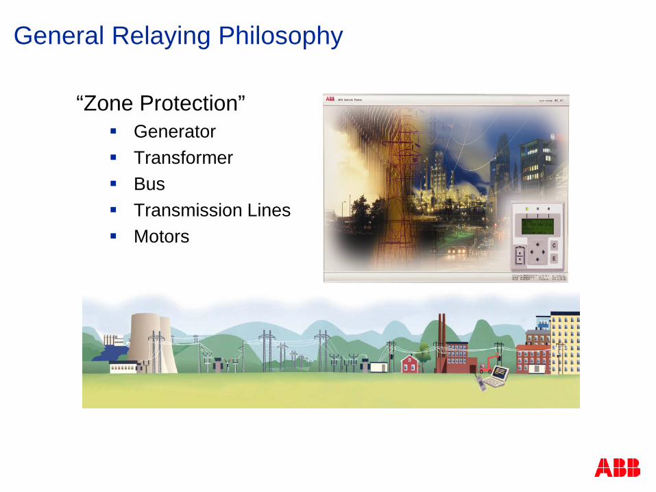
“Zone Protection” Generator Transformer Bus Transmission Lines Motors
General Relaying Philosophy

Zones of Protection
Station A Station B
Station C
Station D
G G
G
M

Zones of Protection
Station A Station B
Station C
Station D
G G
G
M
Generator Protection

Zones of Protection
Station A Station B
Station C
Station D
G G
G
M
Transformer Protection

Zones of Protection
Station A Station B
Station C
Station D
G G
G
M
Bus Protection

Zones of Protection
Station A Station B
Station C
Station D
G G
G
M
Line Protection

Zones of Protection
Station A Station B
Station C
Station D
G G
G
M
Motor/Feeder Protection

Distribution Fuses
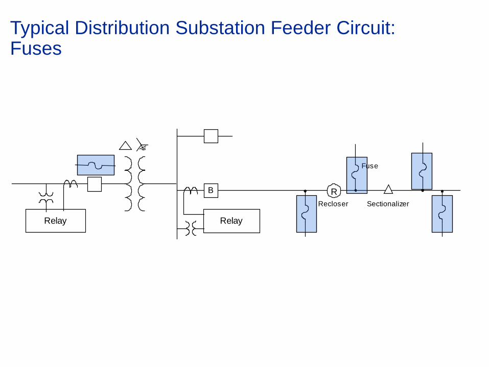
Typical Distribution Substation Feeder Circuit: Fuses
B R
Relay
Fuse
Recloser Sectionalizer
Relay

Continuous current rating Interruption rating Curve characteristics
Minimum melt Total clearing
Distribution Fuses

Fuse Characteristic
Amperes 10
0.1
Tim
e in
Sec
onds
1.0
10
100
1000
100 1000 10000
Minimum Melt (Response Time)
Total Clearing (Interruption Time)
Arc Clearing
Fuse melting time (damage)

K link T link (slower clearing
at high current) Common low current
clearing time based on fuse rating 300 sec <=100 A rating 600 sec > 100 A
rating
Distribution Fuses - Expulsion

Distribution Fuses – Current Limiting
General purpose Rated maximum interrupting
down to current that causes melting in one hour
Melting - 150% to 200%

Distribution Fuses – Current Limiting
Backup Rated maximum interrupting
down to rated minimum interrupting
Requires application with expulsion fuse for low current protection

Fuse Coordination - Rule of Thumb
Amperes 10
0.1
Tim
e in
Sec
onds
1.0
10
100
1000
100 1000 10000
Minimum Melt (Response Time)
Total Clearing (Interruption Time)
Upstream Downstream
Maximum clearing time of downstream fuse should be less than 75% of minimum melt time of upstream fuse (device)

Line terminal
Mounting Bracket
Porcelain Housing
Housing Door Fuse Tube
Mounted Inside Housing Door
Enclosed Open Link
Line terminal
Line terminal
Silicon/Polymer Support
Fuse Holder
Mounting Bracket
Fused Cutout
Arc Arrester
Open Link Fuse Link
Line terminal
Line terminal
Spring Contacts
Silicon/Polymer Support
Mounting Bracket
Fused Cutouts

Distribution Circuit Breakers and Reclosers

Typical Distribution Substation Feeder Circuit: Breakers and Reclosers
B R
Relay
Fuse
Recloser Sectionalizer
Relay

Distribution Circuit Breaker / Recloser
Interruption medium Oil
Vacuum under oil
Vacuum
Operating mechanism Electromechanical (spring charging)
Magnetic actuator
Fault sensing and control Electromechanical
Solid state
Microprocessor

Operating Mechanisms: ESV (spring charge) vs. OVR
Spring charged mechanism
Over 300 total parts
Many moving parts
2000 Operation
Three phase operation only
Magnetic actuator
One moving part
No maintenance
10,000 Operation
Single and three phase

Oil Reclosers vs. Solid Dielectric
Oil Lower interrupting ratings
Clearing time / coordination can vary depending on temperature and condition of oil
Reclosing must be delayed on older units without vacuum bottles to allow for out gassing
2000 Operations or less
Requires 5 – 7 year maintenance schedule
Magnetic Actuation, Solid Dielectric
High fault interrupting capability High load current rating One size fits all amp rating
(interchangeability) Low maintenance costs Environmentally friendly

Medium Voltage Vacuum Breakers
15kV/27kVBreaker ● Single Bottle design
● 15kV & 27kV
● Stored Energy or magnetic
Mechanism
38 KV Breaker ● 38kV
● Two bottle per phase design
● Stored Energy or Magnetic
Mechanism
Vacuum Interruption Definite purpose rated – ANSI C37.06 – 2000 Table 2A

MV Breaker Ratings
Type V two bottle design allows for back-to-back capacitor switching up to 1200 A
Type X R-MAG Type R R-MAG Type V
Voltage , kV 15 15 27 27 38
Continuous Current, A
600 / 1200 / 2000 / 3000
600 / 1200 / 2000 / 3000
1200 / 2000 1200 / 2000 1200 / 2000
Interrupting, kA 12 - 25 12 - 25 12 - 20 12 - 25 25 - 40
BIL 110 110 125 - 150 125 - 150 150 - 200
BIL (Basic Impulse Level): Impulse withstand voltage

Automatic Recloser
Improve reliability of service
Pole-top mounting - eliminates need to build substation
Three-phase unit can replace breaker in substation for lower current ratings
Three Phase
Single Phase

Breakers and Reclosers provide the physical interruption
Both require a protective relay to signal when to operate
© ABB Group October 29, 2013 | Slide 46

Distribution Circuit Protective Relays

WHAT IS RELAYING

Relays
Relays are electromechanical, solid-state (static) or microprocessor-based (digital/numerical) devices that are used throughout the power system to detect abnormal and unsafe conditions and take corrective action
© ABB Group October 29, 2013 | Slide 49

Classification of Relays - Defined in IEEE C37.90
Classification by Function
Protective - Detects intolerable conditions and defective apparatus.
Monitoring - Verify conditions in the protection and/or power system.
Reclosing - Establish closing sequences for a circuit breaker following a protective relay trip.
Regulating - Operates to maintain operating parameters within a defined region.
Auxiliary - Operates in response to other [relay] actions to provide additional functionality
Synchronizing - Assures that proper conditions exist for interconnecting two sections of the power system.

Classification of Relays
Classification by Input
Current (Generator, Motor, Transformer, Feeder)
Voltage (Generator, Motor, Transformer, Feeder)
Power (Generator, Motor, Transformer, Feeder)
Frequency (Generator, Motor, Feeder)
Temperature (Generator, Motor, Transformer)
Pressure (Transformer)
Flow (Generator, Motor, Transformer, Feeder)
Vibration (Generator, Motor)
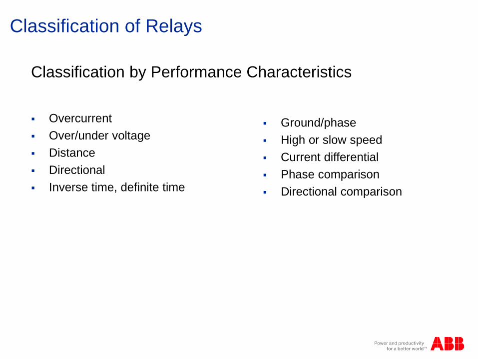
Classification of Relays
Classification by Performance Characteristics
Overcurrent Over/under voltage Distance Directional Inverse time, definite time
Ground/phase High or slow speed Current differential Phase comparison Directional comparison

Classification of Relays
Classification by Technology Electromechanical Solid state (Static) Microprocessor-based (Digital/Numerical)

© ABB Group October 29, 2013 | Slide 54
Relay Input Sources

Typical Distribution Substation Feeder Circuit
B R
Relay
Fuse
Recloser Sectionalizer
Relay

Provide input signal (replica of power system voltage and current) to Relays Reduce level - suitable for relays (typically 120V and
69V depending on line-line or line to neutral connection)
Provide isolation
Purpose

Voltage transformation Electromagnetic voltage transformer
Coupling capacitance voltage transformer
Optical voltage transformer
Current transformation Electromagnetic current transformer
Optical current transformer
Rogowski coil
Types

Do not differ materially from constant-potential power transformers except Power rating is small
Designed for minimum ratio & phase angle error
Voltage (potential) Transformer (VT/PT)

Current or series transformer primary connected in series with the line
Ratio of transformation is approximately inverse ratio of turns. i.e 2000/5
Differs from constant-potential transformer
Primary current is determined entirely by the load on the system and not by its own secondary load
Current Transformer Basics

© ABB Group October 29, 2013 | Slide 60
Secondary winding should never be open-circuited
Flux in the core, instead of being the difference of
the primary & secondary ampere-turns, will now be due to the total primary ampere-turns acting alone
This causes a large increase in flux, producing excessive core loss & heating, as well as high voltage across the secondary terminals
VCD= VS= IL(ZL+ Zlead + ZB) VCD= VS= IL(ZL+ Zlead + ∞) Where ZB is the load presented to the CT by the relay.
Current Transformer Basics
© ABB Group October 29, 2013 | Slide 61
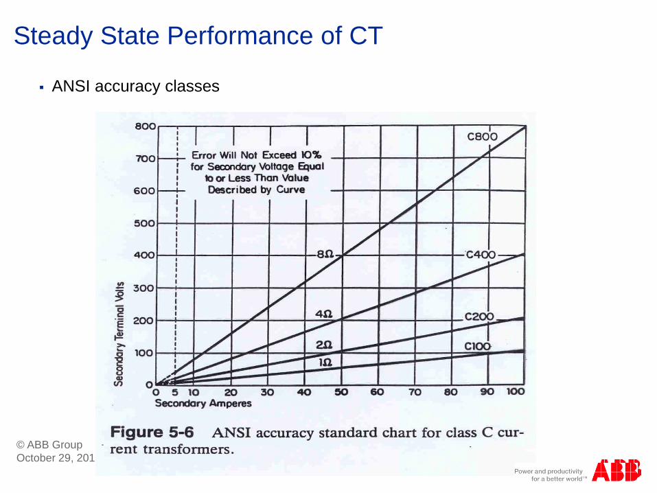
ANSI accuracy classes
Class C indicates that the leakage flux is negligible and the excitation characteristic can be used directly to determine performance. The Ct ratio error can thus be calculated. It is assumed that the burden and excitation currents are in phase and that the secondary winding is distributed uniformly.
Steady State Performance of CT
© ABB Group October 29, 2013 | Slide 62
ANSI accuracy classes
Steady State Performance of CT

D.C. Saturation of a CT
© ABB Group October 29, 2013 | Slide 63
Saturation of a CT may occur as a result of any one or combination of:
Off-set fault currents (dc component)
Residual flux in the core

© ABB Group October 29, 2013 | Slide 64
D.C. Saturation Effect in Current
Over Current Relay Characteristics
© ABB Group October 29, 2013 | Slide 65

Recloser or Breaker Relay Characteristic
Amperes 100
0.1
Tim
e in
Sec
onds
1.0
10
100
1000
1000 10000
Response Time
Breaker / Recloser Interruption Time
Contact opening and arc clearing

Overcurrent Current Device Characteristics
Current in Secondary Amperes
0.1
0.1
Tim
e in
Sec
onds
1
10
0.001
100
10 1000
51
1 100
ANSI Numbers
50 - Instantaneous Overcurrent (No intended delay) Recloser –Fast Curve
51 - Inverse-time Overcurrent Recloser – Slow curve
50
M1 PU

Time Overcurrent Curves
Current in Multiples of Pickup
Definite Time
5
0.2
Tim
e in
Sec
onds
0.4
0.6
0.8
1.0
10 15 20
Moderately Inverse
Inverse
Very Inverse
Extremely Inverse

Time Overcurrent Curve – Time Dial

Recloser Curves
Variety of recloser curves are offered to match existing practices, fuses, conductor annealing, etc.

Distribution Feeder Phase Protection
Pickup tap setting typically is 2, but never less than 1.5, times the normal maximum load interruption rating
Or 1.25 times the short-time maximum load rating of the feeder

Distribution Feeder Ground Protection
Pickup commonly based on one of the following % Above estimated normal load unbalance % Above estimated load unbalance due to switching % Of the phase overcurrent pickup % Of the feeder emergency load rating % Of the feeder normal load rating
Permissible Unbalance
Not above 25% of load current is typical rule-of-thumb, but some allow up to 50%
Pickup setting of ground element to be 2 - 4 times the permissible unbalance

Principles of Feeder Coordination

Principles of Feeder Coordination
Fault Current Vs. Distance to Fault on the Feeder
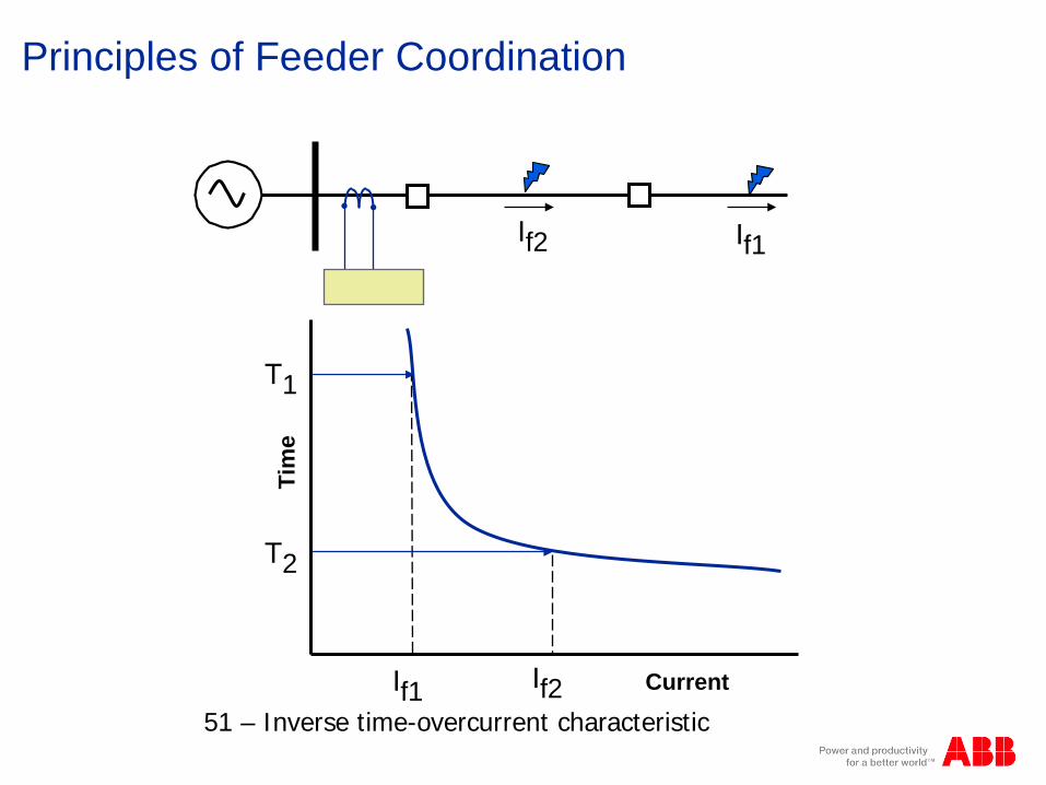
Principles of Feeder Coordination
If2 If1 Ti
me
Current If2 If1
T1
T2
51 – Inverse time-overcurrent characteristic

Principles of Feeder Coordination
If3 If2 If1 Ti
me
Current If3 If2 If1
Relay
Recloser Fuse
Fuse
Minimum Melt
Recloser Relay
CTI - Coordination Time Interval (typical - 0.35 sec)
CTI
CTI
P2
P3
Total Clearing
Interrupt Time
Response Time
P1
Breaker
© ABB Group October 29, 2013 | Slide 76

Principles of Feeder Coordination
Upstream Source-side Protected Backup
B
Downstream Load-side Protecting Down-line
Local (where you are)
LOAD SOURCE
Coordination Terminology R
© ABB Group October 29, 2013 | Slide 77

Principles of Feeder Coordination Ti
me
Current If1M
1. Determine critical fault current locations and values of most down stream device, and plot • Maximum – If1M
Min Zs, at device • Minimum – If1m
Max Zs, end of segment
MIN MAX
If1m
If2M If2M If1M
H R
If1M LOAD LOAD
If1m If2m
© ABB Group October 29, 2013 | Slide 78
Principles of Feeder Coordination Ti
me
Current If1M
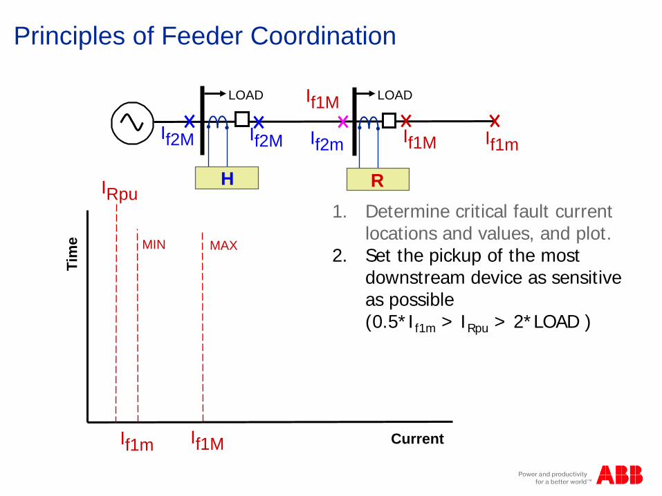
IRpu 1. Determine critical fault current
locations and values, and plot. 2. Set the pickup of the most
downstream device as sensitive as possible (0.5*If1m > IRpu > 2*LOAD )
MIN MAX
If1m
If2M If2M If1M
H R
If1M LOAD LOAD
If1m If2m

Principles of Feeder Coordination Ti
me
Current If1M
IRpu 1. Determine critical fault current
locations and values, and plot. 2. Set most downstream device as
sensitive as possible. 3. Plot operating times of Relay R
based on characteristic of device selected.
T2
T1
MIN MAX
If1m
If2M If2M If1M
H R
If1M LOAD LOAD
If1m If2m
Principles of Feeder Coordination Ti
me
Current If1M
IRpu
T2
T1
MIN MAX
If1m
CTI
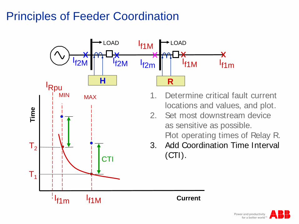
1. Determine critical fault current locations and values, and plot.
2. Set most downstream device as sensitive as possible. Plot operating times of Relay R.
3. Add Coordination Time Interval (CTI).
If2M If2M If1M
H R
If1M LOAD LOAD
If1m If2m

Principles of Feeder Coordination Ti
me
Current If1M
IRpu
T2
T1
MIN MAX
If1m
CTI
Coordination Time Interval CTI is the minimum time interval added to the local device (relay/breaker, fuse) that permits coordination with the next remote upstream device. Coordination is achieved where the remote device will not [normally] operate for faults downstream of the local device, but will operate for all faults between the two.
If2M If2M If1M
H R
If1M LOAD LOAD
If1m If2m

Principles of Feeder Coordination Ti
me
Current If1M
IRpu
T2
T1
MIN MAX
If1m
CTI
Coordination Time Interval Factors that influence CTI are:
• Breaker fault interruption time of upstream device
• Relay dropout (over-travel) time of upstream device [momentum]
• Safety margin to account for setting, tap, CT and operating time errors
• 0.35 seconds typical
If2M If2M If1M
H R
If1M LOAD LOAD
If1m If2m

Principles of Feeder Coordination Ti
me
Current If1M
IRpu
T2
T1
MIN
MAX
MIN
MAX
If1m If2M If2m
4. Add CTI. 5. Determine critical fault current
locations for device H, and plot •Maximum – If2M
Min Zs, at device •Minimum – If2m
Max Zs, end of segment. 6. Plot operating times for H.
If2M If2M If1M
H R
If1M LOAD LOAD
If1m If2m
Principles of Feeder Coordination Ti
me
If1M
IRpu
T2
T1
MIN
MAX
MIN
MAX
If1m
IHpu
If2M If2m
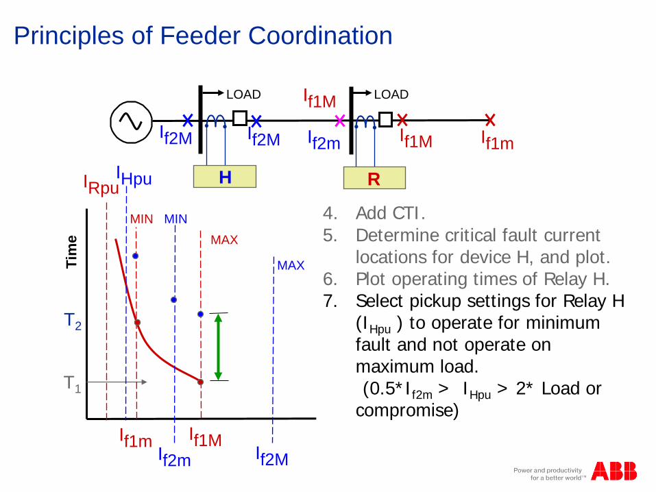
4. Add CTI. 5. Determine critical fault current
locations for device H, and plot. 6. Plot operating times of Relay H. 7. Select pickup settings for Relay H
(IHpu ) to operate for minimum fault and not operate on maximum load.
(0.5*If2m > IHpu > 2* Load or compromise)
If2M If2M If1M
H R
If1M LOAD LOAD
If1m If2m

Principles of Feeder Coordination Ti
me
Current If1M
IRpu
T2
T1
MIN
MAX
MIN
MAX
If1m
IHpu
If2M If2m
4. Add CTI. 5. Determine critical fault current
locations for device H. 6. Plot operating times of Relay H. 7. Select pickup settings for Relay H. 8. Select time dial for Relay H so
curve passes through or above all CTI points.
If2M If2M If1M
H R
If1M LOAD LOAD
If1m If2m
© ABB Group October 29, 2013 | Slide 86

Principles of Feeder Coordination Ti
me
Current If1M
IRpu
MIN
MAX
MIN
MAX
IHpu
If2M
Relay at H is comparatively slow in the defined region of I > If1M
If2M If2M If1M
H R
If1M LOAD LOAD
If1m If2m
© ABB Group October 29, 2013 | Slide 87

Principles of Feeder Coordination Ti
me
Current If1M
IRpu
T2
T1
MIN
MAX
MIN
MAX
IHpu
Relay at H is comparatively slow in the defined region
Apply Instantaneous at H at value greater than 1.25*If1M
IH50pu
If2M If2M If1M
H R
If1M LOAD LOAD
If1m If2m

Fuse Coordination - Rule of Thumb
Amperes 10
0.1
Tim
e in
Sec
onds
1.0
10
100
1000
100 1000 10000
Minimum Melt (Response Time)
Total Clearing (Interruption Time)
Upstream Downstream
Maximum clearing time of downstream fuse should be less than 75% of minimum melt time of upstream fuse.

Fuse Coordination - Rule of Thumb
Amperes 10
0.1
Tim
e in
Sec
onds
1.0
10
100
1000
100 1000 10000
Minimum Melt (Response Time)
Upstream Recloser
Downstream Fuse
Maximum clearing time of downstream fuse should be 75% of the 51 characteristic of the upstream recloser/relay for desirable coordination. It may be necessary, however, to to set the CTI down to as low as 5 cycles to achieve complete feeder coordination.
Fuse - TC

Most utilities require complete coordination between phase time-overcurrent elements down through customer owned protective devices
Those who allow miscoordination only permit it at high current levels where the result is likely to be simultaneous fuse blowing and feeder tripping
Principles of Feeder Coordination

Typical Feeder Coordination
B R
Relay
Recloser
Fuse
115 kV - 13.2/7.62kV Grd Y
15/20/25 MVAZ = 8% @ 15 MVA
125E 100T
100T 65T
I3Ph = 7850I1Ph = 7950
I3Ph = 1100I1Ph = 950
I3Ph = 6300I1Ph = 6000
I3Ph = 2300I1Ph = 950
X
X
X
X
Feeder Coordination Example

Typical Feeder Coordination
Time-Current Curves drawn based on the 13.2kv system currents
Assumptions
Maximum load through recloser = 230A
Maximum load at feeder breaker = 330A
65T and 100T fuses used at lateral taps
Typical Feeder Coordination
With 230A maximum load, select 560A phase pickup setting for the recloser (240%)
for both phase time and instantaneous units
Select 280A pickup for ground overcurrent element (50% of phase pickup) for both ground time and instantaneous units
Select ground time-curve of recloser to coordinate with the 100T fuse

Typical Feeder Coordination
Assuming 400:5 ct ratio for the substation relays, 330A max load = 4.125A secondary
Select 9A tap for phase relays = 720A pickup
Select 4A tap for ground relay = 320A pickup
Select ground relay time-dial to coordinate with recloser ground curve. Select phase relay time dial to coordinate with recloser phase curve

Typical Feeder Coordination
Phase overcurrent relay curve must also coordinate with transformer primary side fuses and transformer frequent-fault capability
Primary side fuse must protect transformer per transformer infrequent-fault capability curve

Typical Feeder Coordination
B R
Relay
Recloser
Fuse
115 kV - 13.2/7.62kV Grd Y
15/20/25 MVAZ = 8% @ 15 MVA
125E 100T
100T 65T
I3Ph = 7850I1Ph = 7950
I3Ph = 1100I1Ph = 950
I3Ph = 6300I1Ph = 6000
I3Ph = 2300I1Ph = 950
X
X
X
X
Feeder Coordination Example

Transformer fuse is the slowest (C&D)
OC Relay and Recloser slow curves faster than 65T and 100T Fuses (3,4,5 & 6)
Typical Feeder Coordination

Typical Feeder Coordination
© ABB Group October 29, 2013 | Slide 99
•Recloser fast curves faster than 65T and 100T Fuses
•Recloser is operating in a “fuse save” mode: •Fast curve (1&2) will open recloser before down stream fuses open
•This will allow a transient fault on a fused tap to be cleared before blowing the fuse
•After a pre-determined number of operations, usually one or two, the fast curves are blocked and the recloser allows the fuse to blow if the fault is in the fuse’s zone of protection.
•If the fault is on the feeder the recloser will operate again, typically going to lockout after one or two more operations.
•Each recloser operation will have a longer open time to allow the fault to clear
•This reduces the outage time on the taps for transient faults, saving the fuse and not having to dispatch a crew to replace the fuse.

The breaker is operating in a fuse blowing mode:
• If the fault is on the tap above the recloser the 100T fuse will open before the breaker
•This reduces the number of customers affected by the outage to only those on the tap.
Typical Feeder Coordination

Relion. Thinking beyond the box.
Designed to seamlessly consolidate functions, Relion relays are smarter, more flexible and more adaptable. Easy to integrate and with an extensive function library, the Relion family of protection and control delivers advanced functionality and improved performance.
This webinar brought to you by the Relion® product family Advanced protection and control IEDs from ABB

Thank you for your participation
Shortly, you will receive a link to an archive of this presentation. To view a schedule of remaining webinars in this series, or for more
information on ABB’s protection and control solutions, visit:
www.abb.com/relion
October 29, 2013 | Slide 102 © ABB Group