Embed Size (px)
Citation preview

1
Thompson River Retaining Wall Rehabilitation
Carlo Elholm, P.Eng. Technical Director – Structural Engineering,
WorleyParsons Westmar
and
Jay Sutton, P.Eng. Senior Project Manager, WorleyParsons Westmar
Paper prepared for presentation at the Bridges in a Climate of Change (B) Session
of the 2009 Annual Conference of the Transportation Association of Canada
Vancouver, British Columbia
2
Abstract Adjacent to the Thompson River, a steel bin retaining wall supporting the roadway of the Trans-Canada Highway near Spences Bridge, BC was at the end of its service life. The metal stringers of the bins were severely corroded and localized perforations allowed the granular roadway materials to wash out during high river levels. The resulting sinkholes in the highway posed a safety hazard, and emergency repairs were necessary with increasing frequency. A detailed inspection of the wall was carried out and a temporary repair program was developed to extend the service life of the structure until a permanent upgrade of the structure could be completed. The 1300 m long wall curves with the natural bend in the river and follows the roadway’s vertical profile with heights varying from 4 m to 8.5 m. Excavation for a replacement wall was not feasible as the roadway is only two lanes wide and an adjacent hillside precluded detour construction. Two concrete retaining wall options were selected for final design and developed for competitive tender. One option used cast-in-place concrete and the other option used precast concrete panels. Each option relied upon threadbar soil anchors drilled through the existing bins and under the roadway to resist horizontal soils loading. The low bidder selected the precast system. This paper will summarize the investigation work performed, the design options reviewed for the replacement wall, and the construction methodology used for this structural rehabilitation project.

3
Introduction The project site is approximately 11 km west of Spences Bridge, which is between Hope and Cache Creek, and adjacent to the Thompson River. To provide sufficient space for construction of the Trans-Canada Highway in 1958, it was necessary to construct the existing steel bin retaining wall. Increasing the slope of the existing hillside or cutting into it was not practical as the Canadian Pacific Railway right of way and existing track was at the top of the embankment. By the end of the 1990s the steel bin wall was at the end of its service life. The metal stringers of the bins were severely corroded and localized perforations allowed the roadway granular materials to be washed out by the river during high water levels. The resulting sinkholes in the highway posed a safety hazard and emergency repairs were necessary with increasing frequency. The BC Ministry of Transportation and Highways engaged Westmar Consultants Inc. to complete a detailed inspection, design temporary repairs, and design permanent repairs. Steel Bin Wall A steel bin wall is a proprietary type of retaining wall constructed with gauge steel that is formed into U-shaped sections, prefabricated, delivered to site and assembled. The system is a hybrid structural and geotechnical arrangement to create a gravity type of retaining wall. After compaction and leveling of the ground, vertical connector elements are placed in the four corners of a rectangular bin. Stringers spanning horizontally are installed and field bolted to the vertical connectors to create four walls. The bin is then filled with granular soil to create a gravity type of retaining wall. Bins are normally 3050 mm wide and this modular system is repeated as necessary to create a cellular arrangement for the full length of the wall. The depth of the bins varies with the height; a higher wall requires deeper cells to resist the sliding force and overturning moment of the retained earth. To provide greater stability, the bin wall is placed with a back slope of six vertical to one horizontal. Condition Inspection A detailed inspection of the wall was carried out in 1999 to assess the feasibility of repair and replacement options. The primary conclusion was that extensive areas of the front face were severely corroded. In general, the corrosion had been from the inside out and the wall was in fact more corroded than was apparent from a casual visual inspection. At many locations, the bin wall appeared entirely serviceable from the exterior front face. The external coating had performed so well that frequently the steel was completely corroded with no visual evidence of distress or corrosion. Modest blows of a hammer or even finger pressure were sufficient force to penetrate the coating and create a new perforation at a location that otherwise had no visual evidence of impending failure. The condition inspection included excavation of a representative sample of the bins. The back and side walls of the bins typically exhibited some corrosion and section loss, but the deterioration was much less than on the inside surface of the front wall. It was estimated that the back wall and side walls could have 25 years further service life. There was no obvious explanation for the significant difference in durability between the front wall and the other three

4
walls of the bins. Possibly, greater daily variations in temperature or directionality of ground water flows contributed to the difference in corrosion, but these are only two hypotheses. The field investigation also showed evidence of physical distress and significant deformation. Undermining of the soil at some locations would have caused substantial gravity loads on those sections of wall founded on firm materials. Some of these sections showed evidence of compression buckling of the vertical connectors. There were also sections of the wall that had responded to the loss of support by settlement and outward rotation. Maintenance of the riprap between the bin wall and the river had been accomplished by end dumping material at the edge of the roadway. In some locations, the falling riprap had impacted the horizontal stringers and caused severe mechanical damage. In other locations, the corroded horizontal stringers were in a state of bending failure and were bulging approximately 100 mm over their 3050 mm span.
Photo 1: Typical Condition of the Bin Wall The field investigation included borehole drilling and standard penetration testing to determine the soil properties which were used in calculating design soil loads from first principles of geotechnical engineering. In addition, chemical analysis was performed on soil samples taken from some of the excavated bins. The granular fills were found to be contaminated with chlorides, presumably from applied road salt. The chloride contamination would have combined with the wet-dry conditions of the granular soil to accelerate corrosion on the inside of the bins. The coating of the steel bins was also examined. On the inside of the bins the coating was black while on the outside the coating was a light silvery color, which on casual observation appeared to be a form of galvanizing. A laboratory analysis and literature search revealed that the two coatings were the same material and the lighter exterior color was a consequence of exposure to the elements and sunlight. A more significant finding of the laboratory analysis was that the coating contained asbestos, a known carcinogen with costly requirements for best health and environmental management.
5
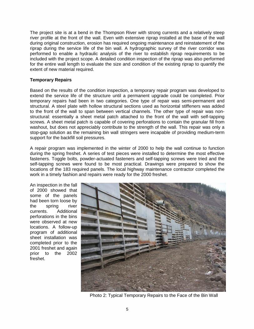
The project site is at a bend in the Thompson River with strong currents and a relatively steep river profile at the front of the wall. Even with extensive riprap installed at the base of the wall during original construction, erosion has required ongoing maintenance and reinstatement of the riprap during the service life of the bin wall. A hydrographic survey of the river corridor was performed to enable a hydraulic analysis of the river to establish riprap requirements to be included with the project scope. A detailed condition inspection of the riprap was also performed for the entire wall length to evaluate the size and condition of the existing riprap to quantify the extent of new material required. Temporary Repairs Based on the results of the condition inspection, a temporary repair program was developed to extend the service life of the structure until a permanent upgrade could be completed. Prior temporary repairs had been in two categories. One type of repair was semi-permanent and structural. A steel plate with hollow structural sections used as horizontal stiffeners was added to the front of the wall to span between vertical channels. The other type of repair was non-structural: essentially a sheet metal patch attached to the front of the wall with self-tapping screws. A sheet metal patch is capable of covering perforations to contain the granular fill from washout, but does not appreciably contribute to the strength of the wall. This repair was only a stop-gap solution as the remaining bin wall stringers were incapable of providing medium-term support for the backfill soil pressures. A repair program was implemented in the winter of 2000 to help the wall continue to function during the spring freshet. A series of test pieces were installed to determine the most effective fasteners. Toggle bolts, powder-actuated fasteners and self-tapping screws were tried and the self-tapping screws were found to be most practical. Drawings were prepared to show the locations of the 183 required panels. The local highway maintenance contractor completed the work in a timely fashion and repairs were ready for the 2000 freshet. An inspection in the fall of 2000 showed that some of the panels had been torn loose by the spring river currents. Additional perforations in the bins were observed at new locations. A follow-up program of additional sheet installation was completed prior to the 2001 freshet and again prior to the 2002 freshet.
Photo 2: Typical Temporary Repairs to the Face of the Bin Wall

6
Preliminary Design Seven options, each with an intended design life of 75 years, were developed during preliminary design phase. All options had to solve one major functional problem. Excavation for a replacement wall was not feasible as the roadway is only two lanes wide and the adjacent hillside precludes detour construction. In addition, a long-term closure of the roadway was not acceptable. The presence of bedrock precluded the practical construction of a sheet pile wall or an H-pile and panel wall. Option 1 was construction of a new steel face in front of the existing wall. The structure would have similarities to a traditional sheet pile wall. Cold-formed steel stringers similar to the existing bin wall stringers would span horizontally. Vertical strongbacks made with a pair of structural steel channels would be spaced at 3 m on centre. Soil anchors would be installed into the existing fill and would be in the gap between the two channels. Option 1 was not advanced for detailed design because its estimated cost exceeded the cost estimate of other options and because the service life of sheet steel had been shown to be limited. Figure 1: Steel Stringers Option 2 was installation of new precast panels in front of the existing bin wall and anchored with soil anchors. The precast panels could be restrained by either or both soil anchors and concrete deadman anchors. During preliminary design, the panels covered the existing bin wall but did not cantilever up to provide additional roadway width. This option was selected for the detailed design phase and ultimately for construction. Option 2 will be described in further detail below.
Figure 2: Precast Concrete Panels

7
Option 3 was the installation of a cast-in-place concrete wall with soil anchors. The concrete would be cast against the existing bin face using one-sided formwork that would be anchored with permanent soil anchors. This option required fewer anchors than a precast system because the wall can be designed to span further than precast panels. The formwork would be repetitive but the actual wall heights do vary considerably so the form panels would require numerous variations. This option was also selected for detailed design and tender. Figure 3: Cast-in-place Concrete Wall Option 4 was the simple concept of filling the existing bins with low strength unreinforced concrete to create a gravity retaining wall. The existing bin wall would act as a form and the bins would be sequentially excavated and filled with concrete made with local aggregates at a site batch plant. The existing front face would eventually corrode away which would have been unsightly but not detrimental to structural performance. This option was not developed further because of the practical challenges of the required depth of excavation, and cost of the large volumes of excavation and concrete. Figure 4: Concrete-filled Bins Option 5 was a hybrid of Options 2 and 4. The existing bins would be excavated and partially filled with low strength concrete which would act as mass footing for a cantilever retaining wall. The wall would be reinforced precast concrete panels positioned prior to placement of the concrete fill. This option was not advanced because it was not cost effective. This option did influence the final design as it introduced the concept of projecting a new concrete wall above the existing bin wall and this idea was incorporated into the final design to increase the roadway width. Figure 5: Precast Wall and Concrete-filled Bins

8
Option 6 was a traditional type of cast-in-place cantilever wall and footing. Each bin would be excavated and a concrete footing constructed to extend past the front of the bin wall. The bin would be backfilled with the original material which would provide dead load to prevent overturning and sliding. For stability of the existing bin wall and roadway, only one bin would be excavated at any one time. A cantilever concrete wall would be constructed on the front of the footing. This option was not advanced because it was the highest cost option. Figure 6: Cantilever Concrete Wall Option 7 was a mechanically stabilized earth (MSE) wall. The existing bins would function as the temporary shoring scheme and would be excavated one at a time. Concrete facing panels would be held in place with geogrid soil reinforcement. This option was not advanced because it was deemed impractical to excavate the full depth of the bins while maintaining traffic flow. The shoring requirements to safely work in the excavated bin were also of concern. The common cost efficiencies of MSE walls were not available because work would have to take place in small 3 m sections. This option required removal of the face of the existing bins which would add a significant disposal cost due to the asbestos within the coating. Figure 7: Mechanically Stabilized Earth Wall Anchor Test Program Cost estimates prepared during preliminary design indicated that soil anchors were a large cost item. The absence of complete geotechnical information contributed to considerable uncertainty in the constructability of anchors and their capacity. The interaction between the anchors and bins was uncertain and the potential for installation difficulties through the bins was deemed to be a significant project risk. Given the scale of the project, the Ministry decided to implement an in-situ anchor testing program. A contract was let to install a total of six soil anchors to collect information on drilling rates, grout take and the feasibility of anchor installation. Both injection bored anchors and threadbar anchors were tested and found to be viable. The testing program also provided accurate information on anchor capacities, allowing anchor spacing and lengths to be optimized.

9
Detailed Design Options Of the seven permanent repair concepts that were developed, two concrete retaining wall options were selected for final design and developed for competitive tender. One option used cast-in-place concrete and the other option used precast concrete panels. Each option relied upon threadbar soil anchors drilled under the roadway to resist horizontal soils loading. The two options were similar in many of the structural details with the obvious difference of off-site panel fabrication compared with cast-in-place construction on site. A cast-in-place system has the benefit of better adaptability for tolerance, fewer operations in the construction sequence, reduced shipping costs, and a generally simpler design. On this project, the cast-in-place method had the practical difficulty of constructing formwork on one side only and using the anchors for resisting the pressures of wet concrete. Formwork panels would need to have substantial strength for this project and typical forming systems could not be used without introducing an excessive quantity of soil anchors. There were also the practical issues of winter concrete work and increased site labour in a somewhat remote location. Concrete delivery costs would also be an issue as the closest ready mix plant is in Merritt. Contractors were invited to bid on one or both options. The lowest submitted tender for the cast-in-place system was $7,382,494. The low bidder, IOTA Construction Ltd. from Chilliwack, selected the precast system at a tendered price of $6,873,430. Vertical integration with an associated company, Pioneer Precast Products, was a commercial advantage to IOTA. Footing A small concrete strip footing was cast along the base of the existing wall to provide a surface on which to set the wall panels and to resist the nominal gravity loads of the panels. In elevation, the footings are level with discrete steps at panel joints. In section, the top of the footing is sloped back at a slope of one vertical to six horizontal to provide uniform grout thickness between the underside of the wall panel and the top of the footing. Footings were cast-in-place during winter low water periods as they are submerged during much of the year. The strip footing was not designed as part of the load system to support the earth pressures because there is no connection between the panels and the footing to transfer either moment or shear. In addition, the footing may not be reliable for resisting soils loading if there is future scour that is not reinstated in a timely manner.
Photos 3 and 4: Ground Preparation and Footing Construction

10
Concrete Wall Panels A total of 421 precast concrete panels were used to construct the new retaining wall that is 1300 m in length. The panels are 300 mm thick, a depth that was governed by the structural requirement to resist concrete punching shear at the anchors. Panel widths were determined by the spacing of existing bin wall vertical connectors as the design intent was to place one panel per bin so that anchors would be drilled through the center of the bins without hitting the bin side walls. In addition, the selected panel sizes would enable transportation on public highways without special overwidth permitting. The panel width is typically 2850 mm with a few exceptions at locations where the existing bin was only 2890 mm wide instead of the typical 3050 mm width. At locations with an expansion joint instead of a shear key, the panel is 2950 mm wide.
Photo 5: Concrete Wall Panels The panel heights vary significantly from 4 m to 8.5 m. The wall height follows the footing elevation on the uneven existing ground and there are frequent changes in wall height. There are typically two anchors per panel with a third anchor added to some of the taller panels and some of the panels with a culvert opening. The anchors are centered in the plan dimension of each panel and aligned vertically. The anchors are not equally spaced in the vertical direction, since soil pressure is not uniform with height. The lower anchor is closer to the end of the panel than the upper anchor in order to equalize the forces in the anchors. With only two anchor supports, the wall panels are statically determinate two-way cantilevers and total bending moments can easily be manually calculated. As a two-way system with discrete support points, the distribution of bending stresses is not uniform. Therefore, the flexural analysis for final design was completed using a grillage analysis to determine the distribution of bending moments in the panels and the concentration of bending stress at the anchor supports. The governing moments are for the cantilevers which create two-way tension stresses on the back face of the wall. There are also positive vertical moments for the span between anchors which cause relatively small tension stresses on the front face. The wall panel reinforcing detailing is similar to the layout used in flat plate building slabs which have column strips and interior strips. Vertical and horizontal reinforcing is concentrated in 1500 mm wide strips at each anchor. Additional shorter bars are concentrated directly at each anchor. The design was tabulated with reinforcing size and spacing varying with panel height.

11
Shear Keys Closure strips act as shear connectors between different panels to share vertical or lateral loads and thus provide redundancy to the wall assembly. The closure pours also reduced tolerance concerns for accurately fitting panels together. The closure pours are approximately 200 mm wide. Hairpin dowels project from the edges of each precast panel into the closure pour and two vertical rebars were field installed. The edge of the wall panels included a formed shear key and the edge was sand-blasted to roughen the surface for improved bond. A self-consolidating concrete was installed in the space to create a monolithic joint. Photo 6: Top View of Shear Key Expansion Joints The use of precast concrete reduces total concrete drying shrinkage since most of the shrinkage occurs in the first month after casting. By the time a panel had been installed and grouted into position, the remaining ultimate shrinkage was relatively small. Expansion joints were installed at approximately 18 m to 27 m spacing. The spacing was varied so that, as much as possible, the expansion joints coincided with footing steps to minimize notch effects where the wall height changes. The expansion joints are made with a 25 mm gap between the edges of adjacent wall panels. On the back of the panels is a full height galvanized steel anchor plate that is attached to one panel only. The cover plate is intended to keep the joint clear of concrete or granular fill. The front of the panel is sealed with a flexible joint sealant to preclude filling with aggregate. The expansion joints are also continuous through the cope beam and the handrail to preclude potential damage as the movement is restrained by these elements. Controlled Density Fill It was necessary to fill the cavity between the precast panels and the existing bin wall so that the anchors could be tested and permanently stressed. It was also desirable to fill the spaces between the horizontal stringer flutes so there would not be a void that could contribute to future roadway settlement with ongoing deterioration and failure of the bin wall. A controlled density fill was placed in the void between the precast panels and the existing metal wall as an alternative value engineering concept to the specified pea gravel. After experimentation, a workable fill made with cement and a locally available gravel mix was developed which produced an economical material in a flowable state. Care was required and

12
staged pours were necessary so that the concrete pressures did not overload the wall or anchors since the pressure of wet concrete exceeds the pressure of granular fill used for design of the wall.
Photo 7: Placing Controlled Density Fill
Anchors The panels are held in place laterally with a total of 871 soil anchors installed through holes cast into the concrete panels, through the existing bin wall structure and under the roadway. The anchors are grouted into the granular fills under the existing highway. The drilling was performed after panel erection so the panel functioned as the template for anchor placement. The anchors are 44 mm diameter threadbars with a bonded length of 6800 mm and an unbonded length of 3000 mm with a design service load of 400 kN. At locations where bedrock was encountered, the bond length was reduced to 4000 mm.
PPhoto 8: Drilling Anchors through the Wall

13
The stressing end of the anchors required typical corrosion protection and also site-specific physical protection. Based on previous experience, installation of additional riprap during the life of the structure by end dumping is probable and a robust protection cap is desirable. There is also a risk of damage to anchors from river debris. The most common method of covering anchors is to use a plastic cover filled with grease, but this cap material was deemed unsuitable for this project. Concrete bolsters were considered but they were not cost effective. The solution developed for this project was a galvanized steel cap. The anchor bearing plate was cut in a circular shape and threaded on the outside. A pipe section was fitted with a welded cover plate on one end and provided with an internal thread on the other end. At the completion of anchor installation, the cap was screwed onto the bearing plate and the cavity was grouted through a hole in the pipe.
Photo 9: Anchor Bearing Plates and Caps Cope Beam A cast-in-place concrete cope beam was installed for the full length of the wall. The cope beam serves as a structural tie to prevent differential movement of the precast panels. It also performs an aesthetic function by smoothing out the tops of the panels to avoid the castellated appearance caused by the rectangular panels trying to follow the roadway profile and obscuring construction and survey tolerances for the panels. The cope beam also provides a secure anchorage for the handrail base connection. The cope beam is fastened to the walls with projecting hairpin dowels. Photo 10: Cope Beam Formwork and Reinforcing Drainage Troughs The existing roadway drainage was through the shoulder fills and sloping fills between the edge of roadway and the top of the bin wall. With the wall extension and increased roadway paving extending to the back face of the cope beam, it was necessary to provide a drainage system. Poor drainage pathways are a common cause of early concrete deterioration so the collection of water and discharge away from the sloping face was deemed a project requirement.
14
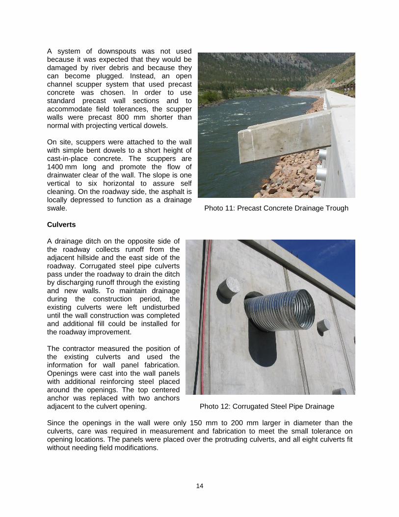
A system of downspouts was not used because it was expected that they would be damaged by river debris and because they can become plugged. Instead, an open channel scupper system that used precast concrete was chosen. In order to use standard precast wall sections and to accommodate field tolerances, the scupper walls were precast 800 mm shorter than normal with projecting vertical dowels. On site, scuppers were attached to the wall with simple bent dowels to a short height of cast-in-place concrete. The scuppers are 1400 mm long and promote the flow of drainwater clear of the wall. The slope is one vertical to six horizontal to assure self cleaning. On the roadway side, the asphalt is locally depressed to function as a drainage swale. Photo 11: Precast Concrete Drainage Trough Culverts A drainage ditch on the opposite side of the roadway collects runoff from the adjacent hillside and the east side of the roadway. Corrugated steel pipe culverts pass under the roadway to drain the ditch by discharging runoff through the existing and new walls. To maintain drainage during the construction period, the existing culverts were left undisturbed until the wall construction was completed and additional fill could be installed for the roadway improvement. The contractor measured the position of the existing culverts and used the information for wall panel fabrication. Openings were cast into the wall panels with additional reinforcing steel placed around the openings. The top centered anchor was replaced with two anchors adjacent to the culvert opening. Photo 12: Corrugated Steel Pipe Drainage Since the openings in the wall were only 150 mm to 200 mm larger in diameter than the culverts, care was required in measurement and fabrication to meet the small tolerance on opening locations. The panels were placed over the protruding culverts, and all eight culverts fit without needing field modifications.

15
After the wall construction was complete, the roadway works were implemented. During this stage, the culverts were excavated and replaced with new sections that projected through the same wall openings. The culvert cantilever dimension was also increased to 1000 mm to direct runoff clear of the base of the wall for increased wall durability. Handrail The original roadway had a steel traffic barrier supported with timber posts but the existing steel bin wall did not have a handrail. The conceptual designs and final design included new concrete median barriers to improve roadway safety, but did not include a handrail at the top of the wall. The Province’s policy for provision of handrails along roadway retaining walls was in transition during the life of the project, and as the wall was completed, it was decided to add a steel handrail along the top. As the wall and cope beam were completed before the decision was made to install a handrail, no prior detailing for attachment of a handrail such as embedded plates or anchor bolts had been made and new field connections were necessary. Photo 13: Handrail Details The contractor was given the option of coring holes and embedding the posts in grout or using epoxy-grouted anchors to secure the base plate of the posts. The contractor chose the latter, and base plates were made with slotted holes and nuts were supplied with plate washers for installation tolerance. The design of the handrail included vertical pickets to prevent small children from climbing through a gap of the more common style of handrail constructed with only a mid rail and top rail. The handrail panels were made in sections approximately 6100 mm long for shipping and for installation in the vertical profile and horizontal curve following the top of the wall. Top rail and mid rail splices were made with pipe dowel inserts that provide tolerance and also permit thermal movement. Splice locations were matched with concrete wall expansion joint locations so the handrail would not bridge the expansion joints. The handrail steel is galvanized and the galvanizing vent holes are directed away from the roadway or face downwards to avoid entraining roadway splash. Wall Installation The wall geometry was largely defined by the existing bin wall layout which had been constructed to suit the river and highway geometry. The complexity of constructing the precast wall was increased due to deflection of the bin wall and uneven rotation and settlement during its 45-year service life.

16
The bin wall construction followed the contours of the ground. Existing as-built drawings were available, but at an early stage of design it was determined that they did not have the accuracy required to create new precast panels. The existing bottom of the bin wall was generally covered with riprap and not visible prior to excavation for footing construction. In the absence of wall height certainty, it was a contractual requirement to field measure as necessary prior to constructing precast panels. The combination of horizontal curve and sloping face means that the shape of the wall is conical. The precast wall layout also needed to consider the variable slopes of the bins because the variations complicate the matching of the panels. For two flat planes to meet at a vertical joint and to conform to conical surfaces with changing radii means there must be a small joint offset at a lower or upper corner. In order to keep the offset from being too large and unsightly as well as maintaining structural integrity, the offset was limited to 25 mm. To match the new, flat precast panels to the existing irregular surface and to provide a best fit to the horizontal curve of the existing river and vertical profile of the highway required accurate field surveys as work proceeded. Surveys were completed after the construction of footings, as the footings have numerous steps to follow the underside of the bin wall and existing rock surface. Precast wall panel dimensions were then determined from the top of wall elevations which were defined by the roadway profile. The survey results were combined with computerized three-dimensional solid modeling of the wall to provide erection data that would ensure a smooth uniform curve that is aesthetically pleasing while satisfying structural engineering demands. The care taken in surveying, solid modelling, shop drawing production, panel fabrication and erection contributed to a precast project with a zero failure rate.
Photo 14: Aerial View of the Concrete Panel Installation Operations

17
Riprap Erosion Protection The bend in the river at the project site exacerbates scour and significant past erosion had occurred, requiring a hydraulic analysis and upgrading of the existing riprap scour protection as part of the project scope. Existing material of appropriate size was reused and a nearby pit was quarried for additional material. The hydraulic analysis determined that material meeting the standard 250 kg class gradation was necessary for most of the wall. In the area of the river bend, 750 kg class riprap was installed. The riprap design also varies with the ground slope. Those areas with steeper slopes have a 7 m width of riprap while the flatter regions have a 5 m width of riprap. The toe of the riprap was keyed into the existing ground line. Due to the potential environmental disturbance, there were areas where the base of the wall could not be excavated because the excavation would take place under water. There were also some areas of bedrock. In these two conditions, the toe of the riprap was made with oversize boulders that were approximately 1500 mm to 2000 mm in dimension. Photo 15: Riprap Installation in Progress Roadworks To implement roadway safety improvements, the new retaining wall is higher than the existing bin wall to provide support for additional fills to increase the roadway width. The shoulder width was increased to 2700 mm and standard Jersey-style concrete median barriers were installed. A space between the median barriers and the cope beam provides a refuge for stranded motorists and a distinct space for cyclists. The two-lane highway was milled, re-graded, and repaved. Minor profile and roadway alignment improvements were also incorporated. Photo 16: Completed Roadworks

18
Schedule The majority of the work was completed from the lower side of the wall on a temporary haul road. The base of the wall is submerged during spring and early summer so project completion during one construction season was deemed to be impractical. Therefore, the wall construction was completed over two winters. Each winter, the contractor mobilized in October and work on the wall was stopped in April. Through the spring and summer of 2005 work continued on the roadway, culverts and handrail and the project was completed in September 2005.
Photo 17: Completed Thompson River Retaining Wall Rehabilitation