Embed Size (px)
Citation preview

Thoracic Cooled-RF Training Presentation

AGENDA
• Patient Selection
• Anatomy Overview – Neuroanatomy
– Lesion targets
• Technique – Diagnostic Block
– Cooled-RF
• Precautions
• Summary
• Appendix

Patient Selection

Thoracic Pain
• The z-joint may be a source of pain in 34-42% of patients with chronic thoracic pain 1
• “Pain in the thoracic region is a common complaint which can be as disabling as cervical or lumbar pain.” 2
1. Manchikanti et al. Anesthesiology Research & Practice 2012 2. Edmondson SJ, Singer KP. Man Ther 1997; 2:132-143.

Significant overlap exists between thoracic segmental pain referral patterns
Adapted from Dreyfuss et al., Spine 1994;19(7):807-11 (Fig.3) and Fukui et al., Reg Anesth 1997;22(4):332-6 (Fig.1,2).
Thoracic Zygapophysial Pain Pattern

• Intervertebral disc
• Spinal dura mater
• Paravertebral muscles
• Ligaments
• Costovertebral joints
• Costotransverse joints
• Zygapophysial joints
• Nerve roots
• Dorsal ramus
• Osseous elements
• Sympathetic elements
Sources of Thoracic Spinal Pain

Patient Selection
• Predominantly axial pain between the T1 and L1 vertebrae
• Greater than 80% pain relief from two separate medial branch blocks (no more than 0.3 ml of injectate per block)
• Chronic axial pain lasting for longer than six months
• Failed conservative therapies
• All other sources of back pain have been ruled out

Anatomy Overview

Thoracic Dorsal Root Nomenclature
• Dorsal root medial branch (MB) travels inferior to the vertebral body of that level. - T1 medial branch travels inferior to the T1 vertebra and contacts the T2 transverse process below.
T1 MB
T2 MB
T5
T1
T3 MB
T4 MB
Adapted from Fig 2.15 of Chua Thesis 1994

Thoracic Dorsal and Ventral Rami
• The superior costotransverse ligament acts as a partition to separate the dorsal and ventral primary rami.
Ventral Ramus
Dorsal Ramus
Superior Costotransverse Ligament
Anterior right
Adapted from Fig 2.6 of Chua Thesis 1994

Dorsal Rami in Transverse Space
• Initially, each dorsal ramus passes through an osseofibrous canal, and dorsally to enter the transverse space.
• Within intertransverse space, dorsal ramus travels 1-2 mm before dividing into lateral and medial branches.
Posterior right
Transverse Process
Medial Branch
Thoracic
Dorsal
Ramus Lateral Branch
Transverse Process
Adapted from Fig 2.8 of Chua Thesis 1994
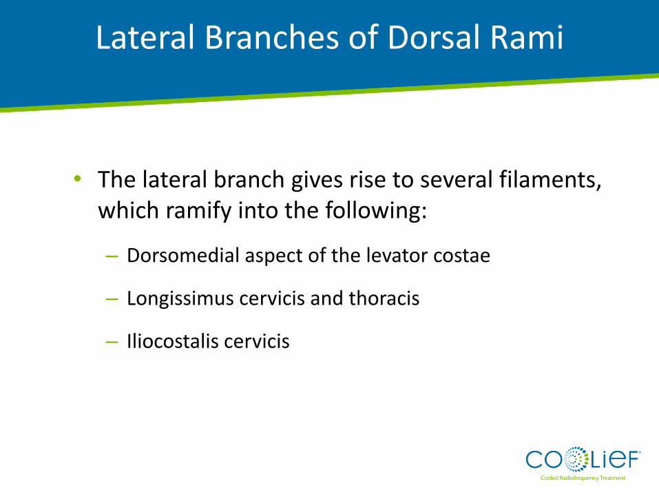
Lateral Branches of Dorsal Rami
• The lateral branch gives rise to several filaments, which ramify into the following:
– Dorsomedial aspect of the levator costae
– Longissimus cervicis and thoracis
– Iliocostalis cervicis

Medial Branches of Dorsal Rami
• The medial branch innervates: – Z-joint joint
– Multifidus
– Spinalis thoracis, splenius cervicis, rhomboids and trapezius (upper levels only)
• The medial branch follows a general path which displays certain level of variability between individuals, and between different levels in the same individual

General Course: Thoracic Dorsal Rami MB
Initially, the MB passes dorsally, laterally and inferiorly within the transverse space, inferior to the corresponding lateral branch.
1
The medial branches enter the posterior compartment of the back by crossing the superolateral corner of the transverse process.
3
Branches run caudally along posterior surface of transverse process, lying in the cleavage plane between the multifidus origin anteromedially and semispinalis postero-laterally.
2
1 3
2
Adapted from Fig 2.15 of Chua Thesis 1994

Variations in MB Path
There are many variations of the general path for the thoracic medial branch.
• Variations observed in individuals between different levels, and sides.
• Variations also observed between individuals.
• Regions display a distinct MB innervation pattern:
• T1-T4, T9-T10
• T5 – T8
• T11
Fig 2.18 of Chua Thesis 1994

T3 Medial
Branch
T4 Medial
Branch
T2
Medial
Branch
Posterior right
Spinous
Process
T1-T4 Medial Branches
Cadaver dissections show that the T1-T4 medial branches cross the transverse processes at the superolateral corner.
Adapted from Fig 2.11 of Chua Thesis 1994

T1-T4 Medial Branch Variability
Superolateral corner of subjacent transverse process.
This point is visible on fluoroscopy, before the MB enters ligaments .
Variability between individuals is minimal for the T1-T4 MBs near the superolateral corner of subjacent transverse process.
Note that variability decreases greatly near the bone surface.
Adapted from Fig 3.3 of Chua Thesis 1994

T1 MB
T2 MB
T5
T1
T3 MB
T4 MB
Adapted from Fig 2.16 of Chua Thesis 1994
General Expected Paths of T1-T4 MBs

• At mid thoracic levels (T5-T8), the MB does not assume contact with the transverse process.
• The nerve appears suspended in the intertransverse space as it passes dorsally.
• It assumes a course parallel to those at typical levels, however T5-T8 medial branches are displaced superiorly.
• These branches then curve medially and slightly inferiorly, remaining separated from the transverse process by the fascicles of the multifidus.
T5-T8 Medial Branch

T5-T8 MBs
Adapted from Fig 2.8 of Chua Thesis 1994
Transverse Process
Posterior right
T7 Medial Branch
Thoracic
Dorsal Ramus Lateral Branch
Transverse Process
T7
T6

Superolateral corner of subjacent transverse process. This point is visible on fluoroscopy, before the MB enters ligaments.
Variability between individuals is significant for the T5-T8 MBs near the superolateral corner of subjacent transverse process.
However, note that variability near the superolateral corner of the transverse processes is contained in the marked red circles.
Adapted from Fig 3.3 of Chua Thesis 1994
T5-T8 Medial Branch Variability

T6 MB
T7 MB
T8 MB
T9
T5
T5 MB
Adapted from Fig 2.16 of Chua Thesis 1994
General Expected Paths of T5-T8 MB
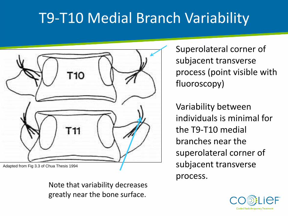
Superolateral corner of subjacent transverse process (point visible with fluoroscopy) Variability between individuals is minimal for the T9-T10 medial branches near the superolateral corner of subjacent transverse process.
Note that variability decreases greatly near the bone surface.
Adapted from Fig 3.3 of Chua Thesis 1994
T9-T10 Medial Branch Variability

T9 MB
T10 MB
T11
T9
Adapted from Fig 2.16 of Chua Thesis 1994
General Expected Paths of T9-T10 MBs

• The T11 medial branch runs across the lateral surface of the root of the T12 superior articular process.
T11 Medial Branch

Bony anatomy similar to lumbar region. Variability between individuals is minimal for the T11 medial branches on subjacent transverse process.
T11 Medial Branch
Adapted from Fig 3.3 of Chua Thesis 1994

T12
T11
T11 MB
Adapted from Fig 2.16 of Chua Thesis 1994
General Expected Path of T11 Medial Branch

Summary of Medial Branch Neuroanatomy
• The MB of the thoracic dorsal ramus shows a variable course.
• Path of the MB is more predictable near the superolateral corner of subjacent transverse processes.
Adapted from Fig 2.16 of Chua Thesis 1994

Technique

Needle T3 MB
Steps: •Advance needle to target point. •Apply 0.3ml contrast medium, followed by 0.3ml local anesthetic.
Target Point: Dorsal surface of the transverse process, opposite the lateral end of its superior border. This point lies just medical to the superior lateral corner of the transverse process.
Adapted from Fig 2.16 of Chua Thesis 1994
T1-T4 and T9-T10 Medial Branch Blocks

Posterior Anterior View Oblique View
T4 TP
T5 TP T5 TP
T4 TP
Adapted from Fig 4.1 (a) and 4.1 (b) of Chua Thesis 1994
T1-T4 and T9-T10 Medial Branch Blocks

Target Point: Intertransverse space
One-Needle Variation Steps: • Insert needle to upper edge of the dorsal surface of rib. • Withdraw needle to the depth of the dorsal surface of the TP. • Apply 0.3 ml contrast medium, followed by 0.3 ml local anesthetic.
Two-Needle Variation Steps: • Insert needle onto dorsal surface of TP. • Insert second needle onto upper edge of the dorsal surface of the rib and withdraw until the same depth as the first needle. • Apply 0.3 ml contrast medium, followed by 0.3 ml local anesthetic.
T5-T8 Medial Branch Blocks

Target Point: Anterior third of the junction between the root of the superior articular process and the root of the transverse process.
T11 MB
Needle
Steps: • Advance needle to target point. • Apply 0.3 ml contrast medium, followed by 0.3 ml local anesthetic.
Adapted from Fig 2.16 of Chua Thesis 1994
T11 Medial Branch Blocks

“Scotty Dog” Diagram
Oblique View
T12
Transverse Processes
T12 V
Adapted from Fig 4.6(a) and 4.6(b) of Chua Thesis 1994
T11 Medial Branch Blocks

• Increase probability of ablating medial branch
– Lesion must encompass variability of nerve path
• Target a known landmark easily visualized with fluoroscopy
• Similar to lumbar and cervical convention: Ablate medial branch before ramification (into z-joint, muscular and cutaneous branches)
• Heat affected area must reside away from sensitive structures
– Nerve root, Pleura
Criteria for Lesion
Cooled-RF Technique

• Medial branch (MB) path is variable, but converges at superolateral corner of transverse process (TP).
• Superolateral corner of the TP is visible under fluoroscopy.
Adapted from Fig 3.3 of Chua Thesis 1994
12 mm Lesion
Diameter Ideal RF Lesion Location
Cooled-RF Technique

• Introducer tip must be directed towards bone
• Procedure must use familiar imaging
• Procedure must use imaging to provide feedback with regards to depth of placement
Criteria for Needle Placement
Cooled-RF Technique

• Straightforward imaging – AP, lateral, ipsi- and contralateral oblique views
• Advance introducer towards the ‘thoracic safe zone’ – Reduced risk of pleural puncture
• Approach constrains placement to target for ablation – Promotes procedural repeatability
Procedural Approach
Cooled-RF Technique

Step 1: Position C-arm in AP; locate treatment level
AP View

Costotranverse joint
lucency to the right
of the needle
Oblique View
Step 2: Rotate C-arm ipsilateral oblique until the costotransverse joint lucency comes into view

Skin
insertion
point
Oblique View
Step 3: Insert Introducer at inferolateral aspect of costotransverse joint lucency level

Land on bone at
superomedial
aspect of joint
lucency
target
insertion
Oblique View
Step 4: Advance Introducer to superomedial aspect of costotransverse joint lucency

Oblique View
Step 5: Position C-arm in AP and walk stylet up to superior margin of transverse process

Ensure radiopaque marker
is at superior margin of
transverse process
Oblique View
Step 6: Replace stylet with probe

Lateral View
Step 7: Confirm depth on lateral

Pinocchio View
Step 8: Confirm placement in Pinocchio View

Step 9: Create Cooled RF lesion
AP View
Set Temp = 60°C
Duration = 2:30 min
Ramp = 80°C/min
• Lateral to medial approach directs introducer tip towards
vertebral body
• Ipsilateral oblique placement constrains lesion to superolateral
aspect of transverse process
• Straightforward imaging aids in identifying transverse process
• Large, spherical lesion targets variability of nerve path
• One introducer insertion reduces iatrogenic injury to the patient
Procedure Summary

Precautions

• Ensure the patient has enough subcutaneous tissue to support
the 10-12mm lesion. Avoid using on patients with very low BMIs.
Precautions

• Imaging and anatomy in thoracic region is less familiar
• Concern related to needle placement and pneumothorax
– Mitigated by Lateral to Medial approach
– In a lateral fluroscopic view, the electrode should NOT be more ventral than the
anterior margin of the transverse process. Placement more ventral to the target
point brings the electrode closer to the pleural cavity and increases the risk of
inadvertent heating of this structure
• Under diagnosis of thoracic z-joint pain
– Current treatment option does not meet needs of the variable anatomy
– Variable anatomy can result in false negatives in diagnostic medial branch blocks
Precautions

Summary

Safety
• Survey of anatomy shows no sensitive structures within target area.
• Advancing introducer towards Thoracic Safe Zone mitigates risk of pleural puncture.
• Obtaining both AP and lateral views confirms location of the introducer tip.
Efficacy
• Large, spherical, Cooled-RF lesion increases probability of successful medial branch ablation even with variability in nerve path.
• Placement on bony landmark (transverse process) provides repeatability for procedure.
Cooled-RF Advantage

Thank You