Embed Size (px)
Citation preview
Surgical Technique Guide
Universal Clamp® Spinal Fixation System
Thoracolumbar Solutions

2 Universal Clamp—Surgical Technique Guide
Universal Clamp—Surgical Technique Guide 3
Zimmer Biomet Spine does not practice medicine. This technique was developed in conjunction
with health care professionals. This document is intended for surgeons and is not intended for
laypersons. Each surgeon should exercise his or her own independent judgment in the diagnosis
and treatment of an individual patient, and this information does not purport to replace the
comprehensive training surgeons have received. As with all surgical procedures, the technique
used in each case will depend on the surgeon’s medical judgment as the best treatment for each
patient. Results will vary based on health, weight, activity and other variables. Not all patients are
candidates for this product and/or procedure.
TABLE OF CONTENTS
Implant Overview 4
Implant Preassembly 5
Loop Preparation 9
Connection to the Rod 10
Reduction 11
Final Construct 14
Implant Removal 14
Kit Contents 15
Supporting Instrumentation and Implants 16
Elevators 17
Important Information on the Universal Clamp Spinal Fixation System 19
4 Universal Clamp—Surgical Technique Guide
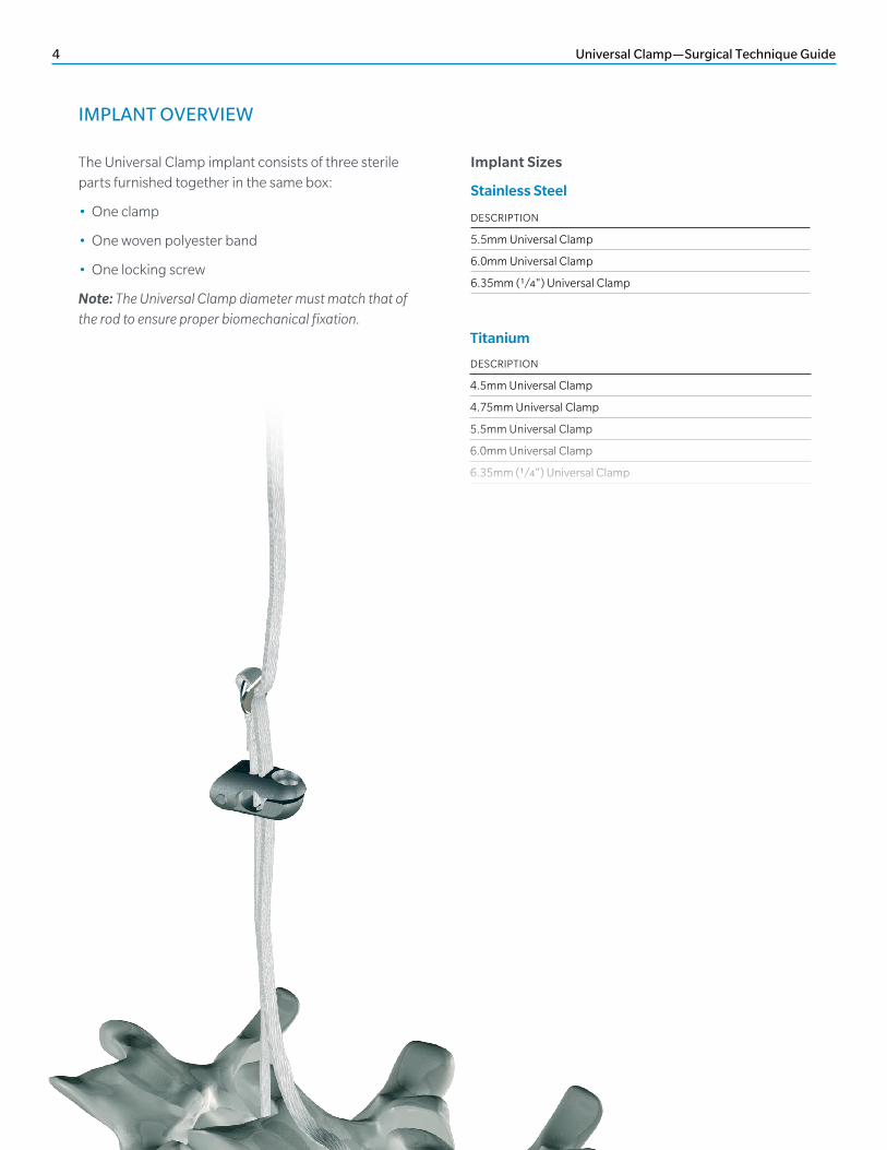
IMPLANT OVERVIEW
The Universal Clamp implant consists of three sterile parts furnished together in the same box:
• One clamp
• One woven polyester band
• One locking screw
Note: The Universal Clamp diameter must match that of the rod to ensure proper biomechanical fixation.
DESCRIPTION
5.5mm Universal Clamp
6.0mm Universal Clamp
6.35mm (1/4") Universal Clamp
DESCRIPTION
4.5mm Universal Clamp
4.75mm Universal Clamp
5.5mm Universal Clamp
6.0mm Universal Clamp
6.35mm (1/4") Universal Clamp
Implant Sizes
Stainless Steel
Titanium
Universal Clamp—Surgical Technique Guide 5
IMPLANT PREASSEMBLY
STEP 1A
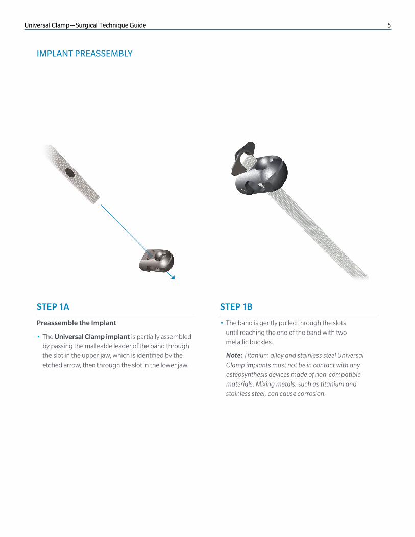
Preassemble the Implant
• The Universal Clamp implant is partially assembled by passing the malleable leader of the band through the slot in the upper jaw, which is identified by the etched arrow, then through the slot in the lower jaw.
STEP 1B
• The band is gently pulled through the slots until reaching the end of the band with two metallic buckles.
Note: Titanium alloy and stainless steel Universal Clamp implants must not be in contact with any osteosynthesis devices made of non-compatible materials. Mixing metals, such as titanium and stainless steel, can cause corrosion.
6 Universal Clamp—Surgical Technique Guide
STEP 2, OPTION 1A
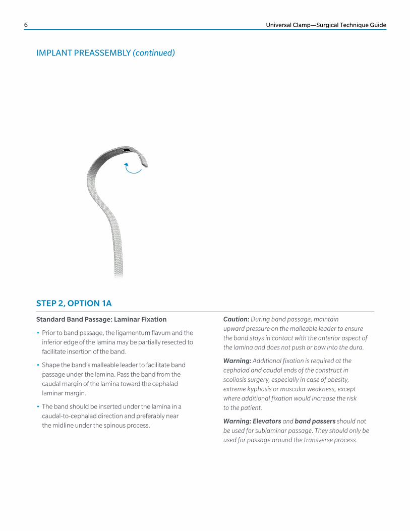
Standard Band Passage: Laminar Fixation
• Prior to band passage, the ligamentum flavum and the inferior edge of the lamina may be partially resected to facilitate insertion of the band.
• Shape the band’s malleable leader to facilitate band passage under the lamina. Pass the band from the caudal margin of the lamina toward the cephalad laminar margin.
• The band should be inserted under the lamina in a caudal-to-cephalad direction and preferably near the midline under the spinous process.
Caution: During band passage, maintain upward pressure on the malleable leader to ensure the band stays in contact with the anterior aspect of the lamina and does not push or bow into the dura.
Warning: Additional fixation is required at the cephalad and caudal ends of the construct in scoliosis surgery, especially in case of obesity, extreme kyphosis or muscular weakness, except where additional fixation would increase the risk to the patient.
Warning: Elevators and band passers should not be used for sublaminar passage. They should only be used for passage around the transverse process.
IMPLANT PREASSEMBLY (continued)
Universal Clamp—Surgical Technique Guide 7
STEP 2, OPTION 1B
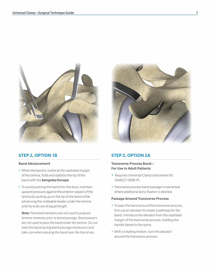
Band Advancement
• When the band is visible at the cephalad margin of the lamina, hold and stabilize the tip of the band with the bengolea forceps.
• To avoid pushing the band into the dura, maintain upward pressure against the anterior aspect of the lamina by pulling up on the tip of the band while advancing the malleable leader under the lamina until its ends are of equal length.
Note: Periosteal elevators are not used to prepare laminar anatomy prior to band passage. Band passers are not used to pass the band under the lamina. Do not twist the band during band passage maneuvers and take care when passing the band near the thecal sac.
STEP 2, OPTION 2A
Transverse Process Band— For Use in Adult Patients
• Requires Universal Clamp Instrument Kit SNA027-0008-PL.
• Transverse process band passage is warranted where additional bony fixation is desired.
Passage Around Transverse Process
• To pass the band around the transverse process, first use an elevator to create a pathway for the band. Introduce the elevator from the cephalad margin of the transverse process, holding the handle lateral to the spine.
• With a rotating motion, turn the elevator around the transverse process.
8 Universal Clamp—Surgical Technique Guide
IMPLANT PREASSEMBLY (continued)
STEP 2, OPTION 2B
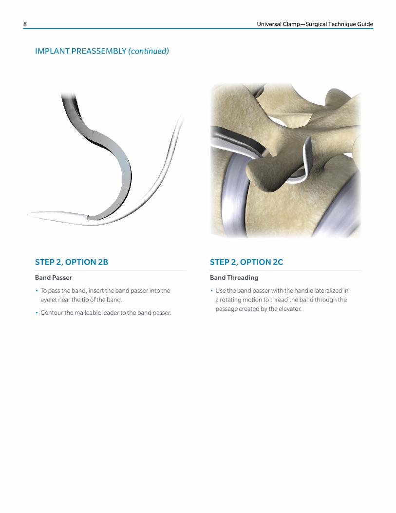
Band Passer
• To pass the band, insert the band passer into the eyelet near the tip of the band.
• Contour the malleable leader to the band passer.
STEP 2, OPTION 2C
Band Threading
• Use the band passer with the handle lateralized in a rotating motion to thread the band through the passage created by the elevator.
Universal Clamp—Surgical Technique Guide 9
LOOP PREPARATION
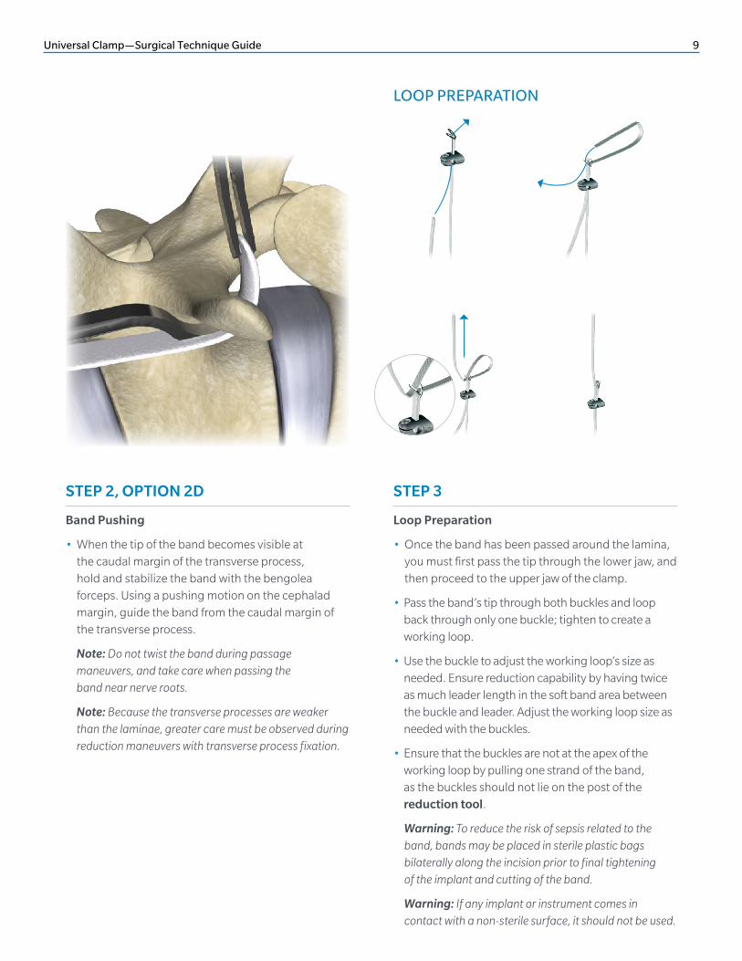
STEP 2, OPTION 2D
Band Pushing
• When the tip of the band becomes visible at the caudal margin of the transverse process, hold and stabilize the band with the bengolea forceps. Using a pushing motion on the cephalad margin, guide the band from the caudal margin of the transverse process.
Note: Do not twist the band during passage maneuvers, and take care when passing the band near nerve roots.
Note: Because the transverse processes are weaker than the laminae, greater care must be observed during reduction maneuvers with transverse process fixation.
STEP 3
Loop Preparation
• Once the band has been passed around the lamina, you must first pass the tip through the lower jaw, and then proceed to the upper jaw of the clamp.
• Pass the band’s tip through both buckles and loop back through only one buckle; tighten to create a working loop.
• Use the buckle to adjust the working loop’s size as needed. Ensure reduction capability by having twice as much leader length in the soft band area between the buckle and leader. Adjust the working loop size as needed with the buckles.
• Ensure that the buckles are not at the apex of the working loop by pulling one strand of the band, as the buckles should not lie on the post of the reduction tool.
Warning: To reduce the risk of sepsis related to the band, bands may be placed in sterile plastic bags bilaterally along the incision prior to final tightening of the implant and cutting of the band.
Warning: If any implant or instrument comes in contact with a non-sterile surface, it should not be used.
10 Universal Clamp—Surgical Technique Guide
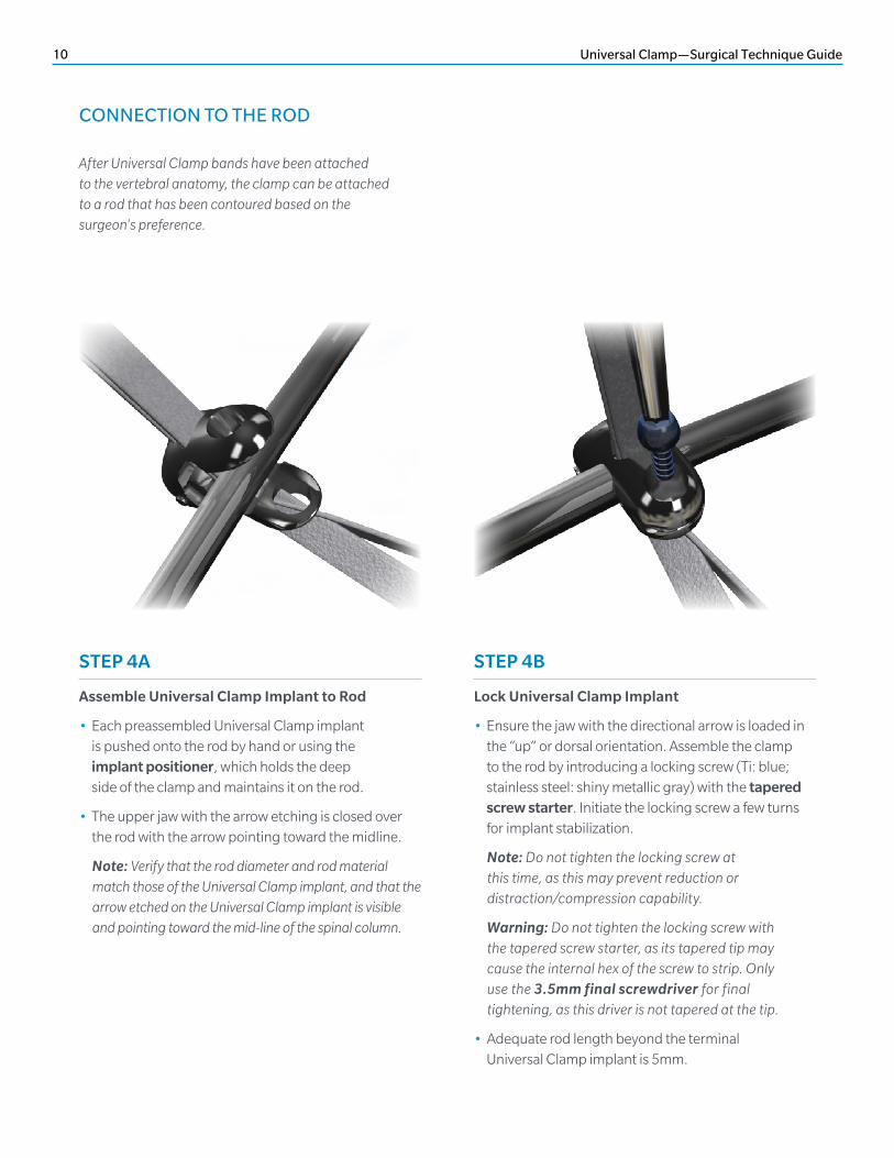
After Universal Clamp bands have been attached to the vertebral anatomy, the clamp can be attached to a rod that has been contoured based on the surgeon's preference.
CONNECTION TO THE ROD
STEP 4A
Assemble Universal Clamp Implant to Rod
• Each preassembled Universal Clamp implant is pushed onto the rod by hand or using the implant positioner, which holds the deep side of the clamp and maintains it on the rod.
• The upper jaw with the arrow etching is closed over the rod with the arrow pointing toward the midline.
Note: Verify that the rod diameter and rod material match those of the Universal Clamp implant, and that the arrow etched on the Universal Clamp implant is visible and pointing toward the mid-line of the spinal column.
STEP 4B
Lock Universal Clamp Implant
• Ensure the jaw with the directional arrow is loaded in the “up” or dorsal orientation. Assemble the clamp to the rod by introducing a locking screw (Ti: blue; stainless steel: shiny metallic gray) with the tapered screw starter. Initiate the locking screw a few turns for implant stabilization.
Note: Do not tighten the locking screw at this time, as this may prevent reduction or distraction/compression capability.
Warning: Do not tighten the locking screw with the tapered screw starter, as its tapered tip may cause the internal hex of the screw to strip. Only use the 3.5mm final screwdriver for final tightening, as this driver is not tapered at the tip.
• Adequate rod length beyond the terminal Universal Clamp implant is 5mm.
Universal Clamp—Surgical Technique Guide 11
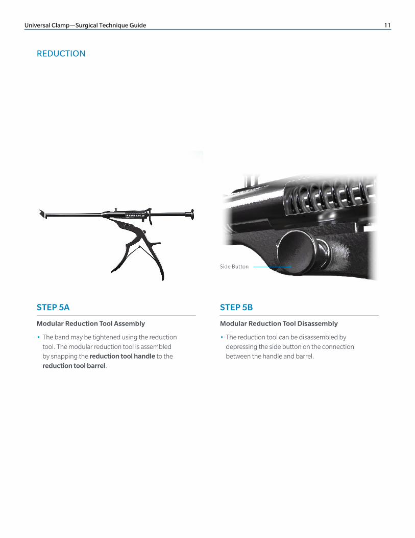
REDUCTION
STEP 5A
Modular Reduction Tool Assembly
• The band may be tightened using the reduction tool. The modular reduction tool is assembled by snapping the reduction tool handle to the reduction tool barrel.
STEP 5B
Modular Reduction Tool Disassembly
• The reduction tool can be disassembled by depressing the side button on the connection between the handle and barrel.
Side Button
12 Universal Clamp—Surgical Technique Guide
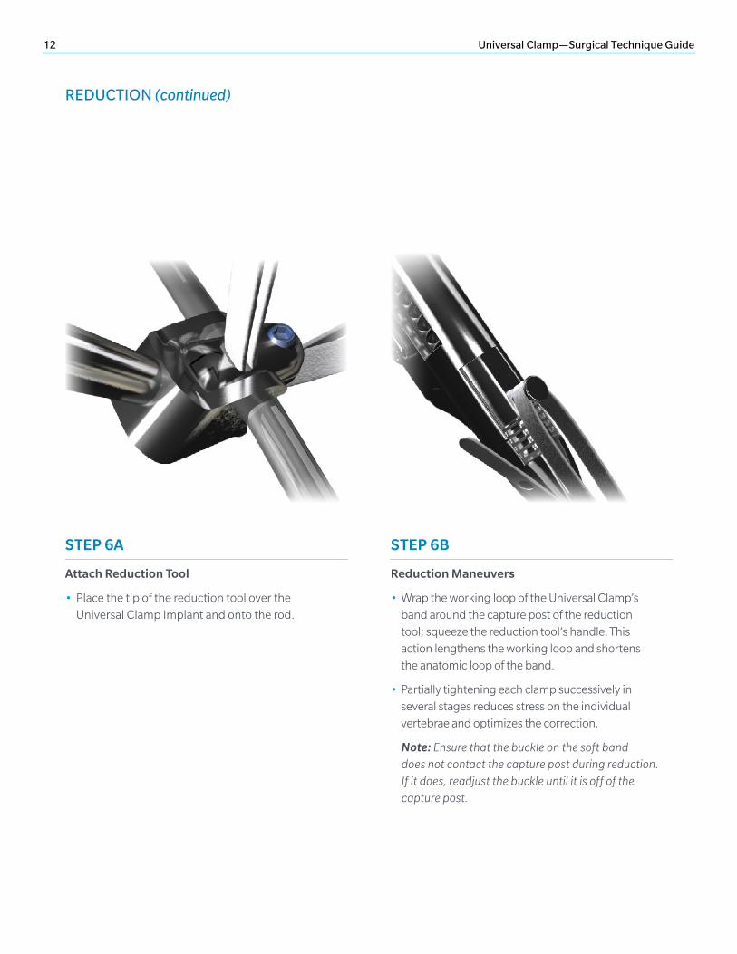
REDUCTION (continued)
STEP 6A
Attach Reduction Tool
• Place the tip of the reduction tool over the Universal Clamp Implant and onto the rod.
STEP 6B
Reduction Maneuvers
• Wrap the working loop of the Universal Clamp’s band around the capture post of the reduction tool; squeeze the reduction tool’s handle. This action lengthens the working loop and shortens the anatomic loop of the band.
• Partially tightening each clamp successively in several stages reduces stress on the individual vertebrae and optimizes the correction.
Note: Ensure that the buckle on the soft band does not contact the capture post during reduction. If it does, readjust the buckle until it is off of the capture post.
Universal Clamp—Surgical Technique Guide 13
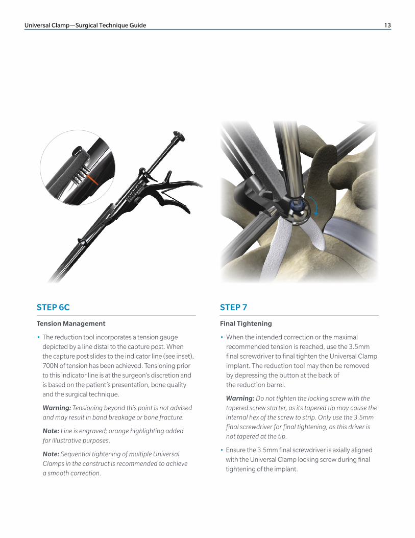
STEP 6C
Tension Management
• The reduction tool incorporates a tension gauge depicted by a line distal to the capture post. When the capture post slides to the indicator line (see inset), 700N of tension has been achieved. Tensioning prior to this indicator line is at the surgeon’s discretion and is based on the patient’s presentation, bone quality and the surgical technique.
Warning: Tensioning beyond this point is not advised and may result in band breakage or bone fracture.
Note: Line is engraved; orange highlighting added for illustrative purposes.
Note: Sequential tightening of multiple Universal Clamps in the construct is recommended to achieve a smooth correction.
STEP 7
Final Tightening
• When the intended correction or the maximal recommended tension is reached, use the 3.5mm final screwdriver to final tighten the Universal Clamp implant. The reduction tool may then be removed by depressing the button at the back of the reduction barrel.
Warning: Do not tighten the locking screw with the tapered screw starter, as its tapered tip may cause the internal hex of the screw to strip. Only use the 3.5mm final screwdriver for final tightening, as this driver is not tapered at the tip.
• Ensure the 3.5mm final screwdriver is axially aligned with the Universal Clamp locking screw during final tightening of the implant.
14 Universal Clamp—Surgical Technique Guide
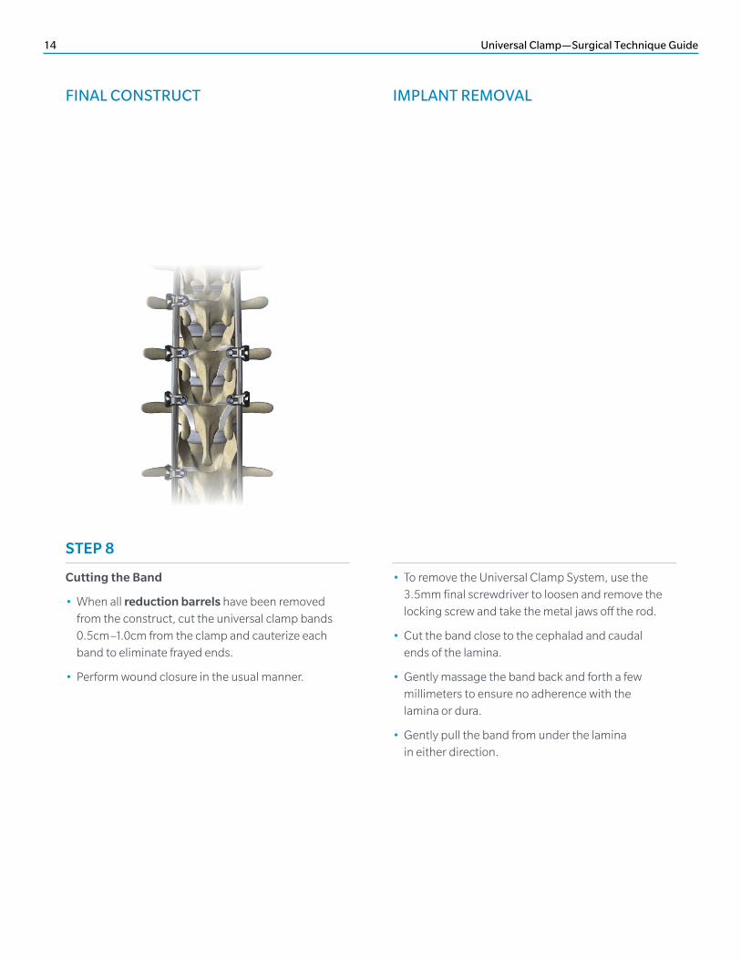
FINAL CONSTRUCT IMPLANT REMOVAL
STEP 8
Cutting the Band
• When all reduction barrels have been removed from the construct, cut the universal clamp bands 0.5cm–1.0cm from the clamp and cauterize each band to eliminate frayed ends.
• Perform wound closure in the usual manner.
• To remove the Universal Clamp System, use the 3.5mm final screwdriver to loosen and remove the locking screw and take the metal jaws off the rod.
• Cut the band close to the cephalad and caudal ends of the lamina.
• Gently massage the band back and forth a few millimeters to ensure no adherence with the lamina or dura.
• Gently pull the band from under the lamina in either direction.
Universal Clamp—Surgical Technique Guide 15
IMPLANT REMOVAL KIT CONTENTS
DESCRIPTION PART NUMBER
Bengolea Forceps, 20cm SN2027-1-02270
Bengolea Forceps, 26cm SN2027-1-02276
Tapered Screw Starter SN2027-1-02512
Implant Positioner SN2027-1-02600
Elevator, 45° Right SN2027-1-02103
Elevator, 45° Left SN2027-1-02104
Elevator, 90° Right SN2027-1-02101
Elevator, 90° Left SN2027-1-02110
Band Passer, 45° Right SN2027-1-02113
Band Passer, 45° Left SN2027-1-02200
Band Passer, 90° Right SN2027-1-02111
Band Passer, 90° Left SN2027-1-02102
Straight Elevator SN2027-1-02112
Reduction Tool Barrel SN2027-1-02200
Reduction Tool Handle SN2027-1-02201
Final Screwdriver, 3.5mm SN2027-1-02570
Implants
Instruments
DESCRIPTION PART NUMBERS*
Universal Clamp, Band SN2027-0-20000, SNA027-0-20000
Universal Clamp, Locking Screw, Titanium Alloy SN2027-0-20006S, SNA027-0-20006S
Universal Clamp, 4.5mm, Titanium Alloy SN2027-0-20045
Universal Clamp, 4.75mm, Titanium Alloy SN2027-0-20047
Universal Clamp, 5.5mm, Titanium Alloy SN2027-0-20055, SNA027-0-20055
Universal Clamp, 5.5mm, Clamp, Titanium Alloy SN2027-0-20155, SNA027-0-20155
Universal Clamp, 6.0mm, Titanium Alloy SN2027-0-20060, SNA027-0-20060
Universal Clamp, 6.0mm, Clamp, Titanium Alloy SN2027-0-20160, SNA027-0-20160
Universal Clamp, 6.35mm, Titanium Alloy SN2027-0-20063
Universal Clamp, Locking Screw, Stainless Steel SN2027-0-30006S, SNA027-0-30006S
Universal Clamp, 5.5mm, Stainless Steel SN2027-0-30055, SNA027-0-30055
Universal Clamp, 6.0mm, Stainless Steel SN2027-0-30060, SNA027-0-30060
Universal Clamp, 6.35mm, Stainless Steel SN2027-0-30063, SNA027-0-30063
*SN2 and SNA part numbers are equivalent.
16 Universal Clamp—Surgical Technique Guide
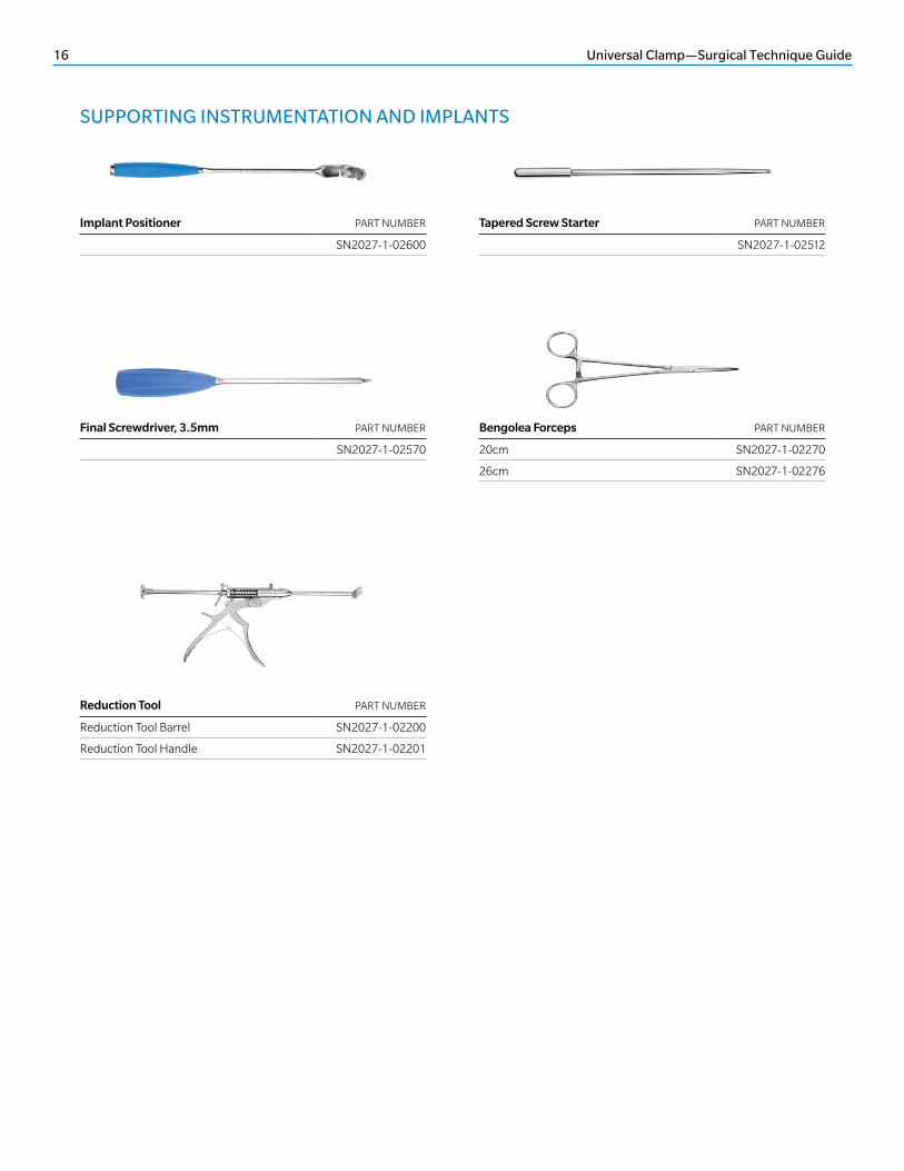
SUPPORTING INSTRUMENTATION AND IMPLANTS
Implant Positioner PART NUMBER
SN2027-1-02600
Final Screwdriver, 3.5mm PART NUMBER
SN2027-1-02570
Reduction Tool PART NUMBER
Reduction Tool Barrel SN2027-1-02200
Reduction Tool Handle SN2027-1-02201
Bengolea Forceps PART NUMBER
20cm SN2027-1-02270
26cm SN2027-1-02276
Tapered Screw Starter PART NUMBER
SN2027-1-02512
Universal Clamp—Surgical Technique Guide 17
SUPPORTING INSTRUMENTATION AND IMPLANTS (continued)
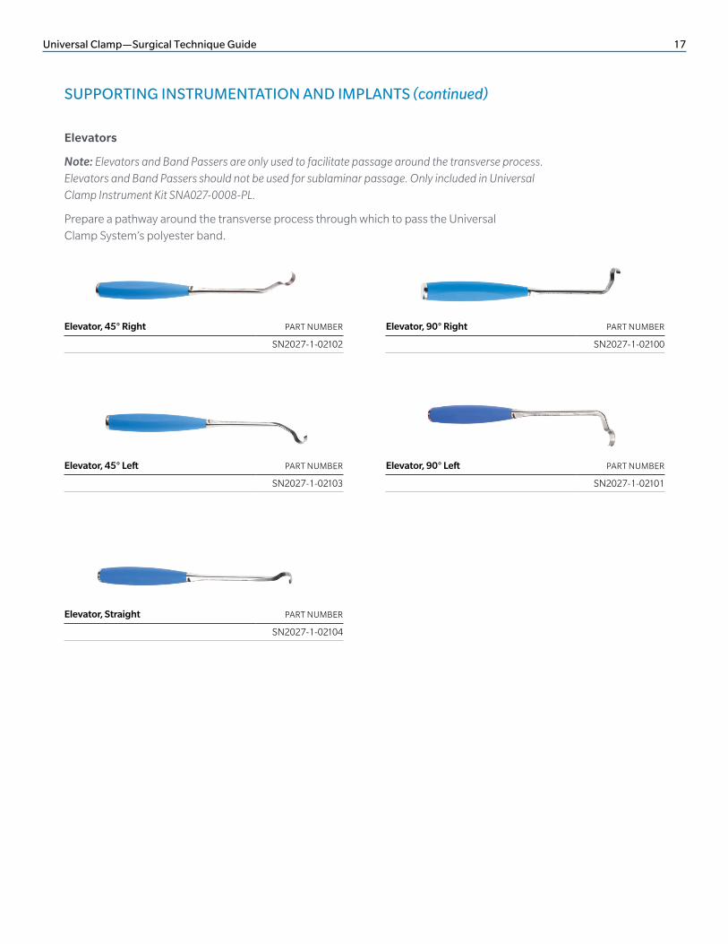
Elevators
Note: Elevators and Band Passers are only used to facilitate passage around the transverse process. Elevators and Band Passers should not be used for sublaminar passage. Only included in Universal Clamp Instrument Kit SNA027-0008-PL.
Prepare a pathway around the transverse process through which to pass the Universal Clamp System’s polyester band.
Elevator, 45° Right PART NUMBER
SN2027-1-02102
Elevator, 90° Left PART NUMBER
SN2027-1-02101
Elevator, 45° Left PART NUMBER
SN2027-1-02103
Elevator, 90° Right PART NUMBER
SN2027-1-02100
Elevator, Straight PART NUMBER
SN2027-1-02104
18 Universal Clamp—Surgical Technique Guide
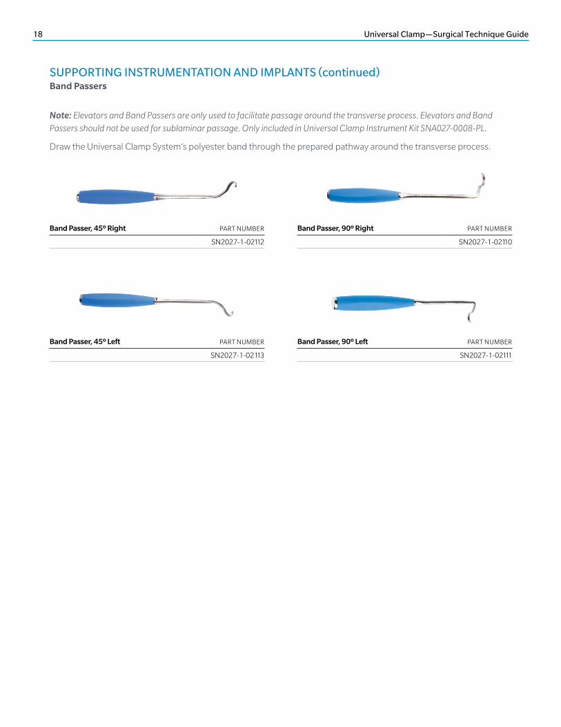
Note: Elevators and Band Passers are only used to facilitate passage around the transverse process. Elevators and Band Passers should not be used for sublaminar passage. Only included in Universal Clamp Instrument Kit SNA027-0008-PL.
Draw the Universal Clamp System’s polyester band through the prepared pathway around the transverse process.
Band Passer, 45º Right PART NUMBER
SN2027-1-02112
Band Passer, 45º Left PART NUMBER
SN2027-1-02113
Band Passer, 90º Left PART NUMBER
SN2027-1-02111
Band Passer, 90º Right PART NUMBER
SN2027-1-02110
SUPPORTING INSTRUMENTATION AND IMPLANTS (continued)Band Passers
Universal Clamp—Surgical Technique Guide 19
Description
The Universal Clamp Spinal Fixation System consists of a woven band with a stiff guiding section at one end and metal buckles at the other end, implantable grade metal clamps that mate with 4.5mm–6.35mm diameter rods and an implantable grade metal locking screw that tightens the clamp over the band securing it to the connecting rod.
Implants made from implantable-grade titanium, implantable-grade titanium alloy and implantable-grade cobalt chromium may be used together. Due to the risk of galvanic corrosion, never use titanium, titanium alloy and/or cobalt chromium with stainless steel in the same construct. All implants are provided sterile and are single use only; the implants should not be re-used or re-sterilized under any circumstances.
The Universal Clamp System implants are fabricated from materials as shown in the table above.
Indications
The Universal Clamp System is a temporary implant for use in orthopedic surgery. The system is intended to provide temporary stabilization as a bone anchor during the development of solid bony fusion and aid in the repair of bone fractures. The indications for use include the following applications:
• Spinal trauma surgery, used in sublaminar or facet wiring techniques;
• Spinal reconstructive surgery, incorporated into constructs for the purpose of correction of spinal deformities such as idiopathic and neuromuscular scoliosis in patients 8 years of age and older, adult scoliosis, kyphosis and spondylolisthesis;
• Spinal degenerative surgery, as an adjunct to spinal fusions.
The Universal Clamp System may also be used in conjunction with other medical-grade implants made of similar metals whenever “wiring” may help secure the attachment of the other implants.
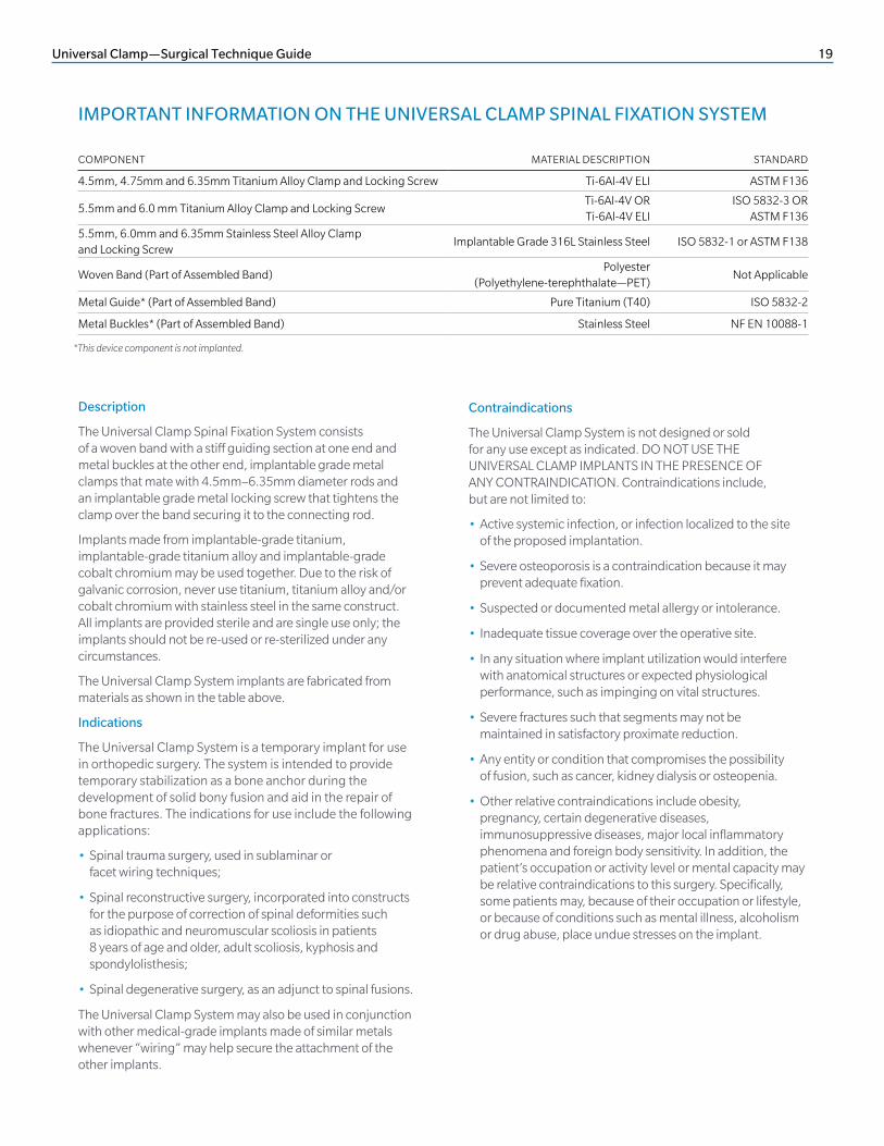
IMPORTANT INFORMATION ON THE UNIVERSAL CLAMP SPINAL FIXATION SYSTEM
*This device component is not implanted.
Contraindications
The Universal Clamp System is not designed or sold for any use except as indicated. DO NOT USE THE UNIVERSAL CLAMP IMPLANTS IN THE PRESENCE OF ANY CONTRAINDICATION. Contraindications include, but are not limited to:
• Active systemic infection, or infection localized to the site of the proposed implantation.
• Severe osteoporosis is a contraindication because it may prevent adequate fixation.
• Suspected or documented metal allergy or intolerance.
• Inadequate tissue coverage over the operative site.
• In any situation where implant utilization would interfere with anatomical structures or expected physiological performance, such as impinging on vital structures.
• Severe fractures such that segments may not be maintained in satisfactory proximate reduction.
• Any entity or condition that compromises the possibility of fusion, such as cancer, kidney dialysis or osteopenia.
• Other relative contraindications include obesity, pregnancy, certain degenerative diseases, immunosuppressive diseases, major local inflammatory phenomena and foreign body sensitivity. In addition, the patient’s occupation or activity level or mental capacity may be relative contraindications to this surgery. Specifically, some patients may, because of their occupation or lifestyle, or because of conditions such as mental illness, alcoholism or drug abuse, place undue stresses on the implant.
COMPONENT MATERIAL DESCRIPTION STANDARD
4.5mm, 4.75mm and 6.35mm Titanium Alloy Clamp and Locking Screw Ti-6Al-4V ELI ASTM F136
5.5mm and 6.0 mm Titanium Alloy Clamp and Locking ScrewTi-6Al-4V ORTi-6Al-4V ELI
ISO 5832-3 ORASTM F136
5.5mm, 6.0mm and 6.35mm Stainless Steel Alloy Clamp and Locking Screw
Implantable Grade 316L Stainless Steel ISO 5832-1 or ASTM F138
Woven Band (Part of Assembled Band)Polyester
(Polyethylene-terephthalate—PET)Not Applicable
Metal Guide* (Part of Assembled Band) Pure Titanium (T40) ISO 5832-2
Metal Buckles* (Part of Assembled Band) Stainless Steel NF EN 10088-1
20 Universal Clamp—Surgical Technique Guide
Warnings and Precautions
The following are specific warnings, precautions and adverse effects associated with use of the Universal Clamp System that should be understood by the surgeon and explained to the patients. General surgical risk should be explained to the patients prior to surgery.
• Implantation should be performed only by experienced spinal surgeons.
• All implants are intended for single use only. Single-use devices should never be re-used or re-sterilized. Possible risks associated with re-use of or re-sterilization of single-use devices include:
• Mechanical malfunction
• Transmission of infectious agents
• Metal sensitivity has been reported following exposure to orthopedic implants. The most common metals associated with metal sensitivities (nickel, cobalt and chromium) are present in medical-grade stainless steel and cobalt-chrome alloys.
• After solid fusion occurs, this device serves no functional purpose and may be removed. In most cases, removal is indicated because the implant is not intended to transfer or support forces developed during normal activities after several months. Any decision to remove the device must be made by the physician and the patient, taking into consideration the patient’s general medical condition and the potential risk to the patient of a second surgical procedure.
• Implants can break when subjected to the prolonged loading associated with delayed union or non-union. Internal fixation systems are load-sharing devices that are used to obtain alignment until normal healing occurs. If healing is delayed or does not occur, the implant may eventually fail. The degree or success of union, loads produced by weight bearing and activity levels will, among other conditions, dictate the longevity of the implant. Patients should be fully informed of the risks of implant failure.
• Universal precautions should be observed by all end users that work with contaminated or potentially contaminated medical devices. Caution should be exercised when handling devices with sharp points or cutting edges to prevent injuries during and after surgical procedures and reprocessing.
Additional preoperative, intraoperative and postoperative warnings and precautions:
Preoperative
• Never use titanium, titanium alloy and/or cobalt chromium with stainless steel in the same implant construct; otherwise, galvanic corrosion may occur.
Intraoperative
• Insertion of an implant must be done using the instruments designed and supplied for this purpose and the technique specific to each device. The details of this insertion are found in the Universal Clamp System Surgical Technique supplied by Zimmer Biomet Spine.
• Bone integrity should be verified. Osteoporosis or any other bone tissue diseases that may alter the mechanical properties of the vertebrae must be taken into account when deciding whether to insert a Zimmer Biomet Spine Universal Clamp System.
• Elevators and Band Passers should not be used for sublaminar passage. They should only be used for passage around the transverse process.
• Be sure to follow the markings on the reduction instrument. Going beyond the markings and forced use may result in excessive tension and, depending on bone quality, bony fracture.
• Be sure to insert the band in the right direction in the Universal Clamp implant clamp, as indicated by an arrow engraved on the upper jaw of the clamp.
• Be sure to follow the instructions for preparing the loop. The woven band that makes up the loop is attached using the metal buckles, as described in the Surgical Technique.
• Be sure to place the Universal Clamp implant properly on compatible rod by verifying that the arrow engraved on the clamp is visible and pointing toward the mid-line of the spinal column.
• Be sure not to over tighten the Universal Clamp implant’s locking screw prior to performing reduction or compression/distraction maneuvers. Over tightening reduces compression/detraction capabilities and increases the risk of damage to the band. Two tightening turns are sufficient prior to compression/distraction.
• Be sure not to over tighten the locking screw using the locking screw holder. The end of the locking screw holder may cause damage to the imprint of the locking screw head.
• Be sure to avoid any risks of sepsis related to the band. Bands may be placed in sterile plastic bags bilaterally along the incision.
• Be sure to firmly tighten the Universal Clamp implant locking screw. Only use the final screwdriver for final tightening, as this driver is not tapered at the tip.
• Ensure final screwdriver is axially aligned with the Universal Clamp locking screw during final tightening of the implant.
Universal Clamp—Surgical Technique Guide 21
• Additional fixation is required at the cephalad and caudal ends of the construct in scoliosis surgery, especially in case of obesity, extreme kyphosis or muscular weakness, except where additional fixation would increase the risk to the patient.
• If any implant or instrument comes in contact with a non-sterile surface it should not be used.
Postoperative
• Adequately instruct the patient. Postoperative care and the patient’s ability and willingness to follow instructions are one of the most important aspects of successful bone healing. The patient must be made aware of the limitations of the implant and that physical activity and full weight bearing have been implicated in fracture. The patient should understand that an implant is not as strong as normal, healthy bone and will fracture if excessive demands are placed on it in the absence of complete bone healing. An active, debilitated, or demented patient who cannot properly use weight-supporting devices may be particularly at risk during postoperative rehabilitation.
Adverse Effects
Complications and adverse reactions have been reported with the use of similar spinal instrumentation systems. These adverse effects, including the possibility of death, should be discussed with the patient prior to surgery.
Additional surgery may be required to correct any of these potential adverse effects.
1. Non-union, delayed union.
2. Disassembly, fraying, kinking, loosening, bending or breakage of any or all of the Universal Clamp System implant components.
3. Metal sensitivity, polyester sensitivity or allergic reaction to a foreign body.
4. Infection.
5. Foreign body reaction to the implants including possible tumor formation.
6. Pain, discomfort, or abnormal sensations due to the presence of the device.
7. Pressure on the skin from component parts, where there is inadequate tissue coverage over the implant causing skin irritation.
8. Loss of proper spinal curvature, correction height and/or reduction.
9. Implants cutting through soft osteoporotic, osteopenic or cancellous bone.
10. Bone forming around the implant making removal difficult or impossible.
11. Cessation of growth in the operated portion of bone.
12. Decrease in bone density due to stress shielding.
13. Vascular and/or nerve damage due to surgical trauma or presence of the device. Neurological difficulties including bowel and/or bladder dysfunction, impotence, retrograde ejaculation, and paraesthesia.
14. Bursitis.
15. Dural leak.
16. Paralysis.
17. Death.
18. Erosion of blood vessels due to the proximity of the device, leading to hemorrhage and/or death.
Magnetic Resonance Imaging (MRI) Safety and Compatibility
The Universal Clamp System has not been evaluated for safety and compatibility in the MR (Magnetic Resonance) environment. The Universal Clamp System has not been tested for heating or migration in the MR environment.
In the event of exposure to foreseeable environmental conditions such as magnetic fields the user and/or patient should be informed of the following:
Precautions
• This device has not been evaluated for safety and compatibility in the MR environment.
• This device has not been tested for heating or migration in the MR environment.
• There is a potential for heating and migration in the MR environment.
• There is the potential for metal implants to create MR imaging artifacts in the vicinity of the implant.

22 Universal Clamp—Surgical Technique Guide
NOTES

Disclaimer: This document is intended exclusively for physicians and is not intended for laypersons. Information on the products and procedures contained in this document is of a general nature and does not represent and does not constitute medical advice or recommendations. Because this information does not purport to constitute any diagnostic or therapeutic statement with regard to any individual medical case, each patient must be examined and advised individually, and this document does not replace the need for such examination and/or advice in whole or in part.
Caution: Federal (USA) law restricts this device to sale by or on the order of a physician. Rx Only. For product information, including indications, contraindications, warnings, precautions, potential adverse effects and patient counseling information, see the package insert and www.zimmerbiomet.com.
©2016 Zimmer Biomet Spine, Inc. All rights reserved.
All content herein is protected by copyright, trademarks and other intellectual property rights, as applicable, owned by or licensed
to Zimmer Biomet Spine, Inc. or its affiliates unless otherwise indicated, and must not be redistributed, duplicated or disclosed,
in whole or in part, without the express written consent of Zimmer Biomet Spine. This material is intended for health care professionals,
the Zimmer Biomet Spine sales force and authorized representatives. Distribution to any other recipient is prohibited.
0344.1-US-en-REV1116
800.447.3625 ⁄ zimmerbiomet.com
Distributed by: Zimmer Biomet Spine, Inc. 10225 Westmoor Dr. Westminster, CO 80021 USA Tel +1 800.447.3625
Manufactured by: Zimmer Spine Cité Mondiale 23, Parvis des Chartrons 33080 Bordeaux - France Tel +33(0)5 56 00 18 20 Fax +33(0)5 56 00 18 21