Embed Size (px)
Citation preview
13TH INTERNATIONAL DEPENDENCY AND STRUCTURE MODELLING CONFERENCE, DSM’11 CAMBRIDGE, MASSACHUSETTS, USA, SEPTEMBER 14 – 15, 2011
THREE APPROACHES TO COMPLEX SYSTEM DECOMPOSITION Noemi Chiriac1, Katja Hölttä-Otto1, Dusan Lysy2 and Eun Suk Suh2 1University of Massachusetts Dartmouth, USA 2Xerox Corporation, USA
Most work on component or function based DSMs thus far starts with an assumption that decomposition is trivial. In this paper we introduce three distinct approaches to decomposing a complex system: assembly decomposition, functional decomposition and service based decomposition. Then we apply these guidelines to a Xerox printing system. We conclude that the results of architectural analysis, for a complex system, are directly affected by the approach taken to decompose the system and the whole to part ratio.
Keywords: Complex system development, decomposition, system architecture, DSM, whole to part ratio
1 INTRODUCTION In this paper we introduce three distinct approaches to decompose a complex system: assembly decomposition, functional decomposition and service based decomposition. These three approaches are then applied to a Xerox printing system.
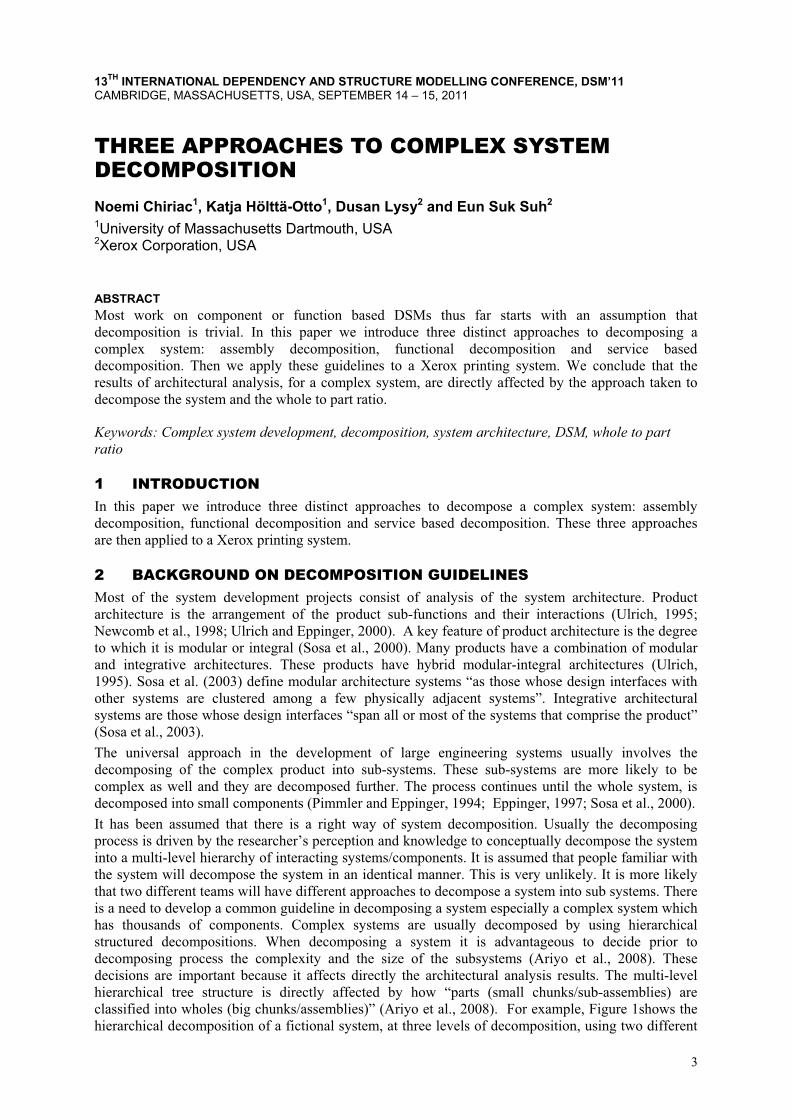
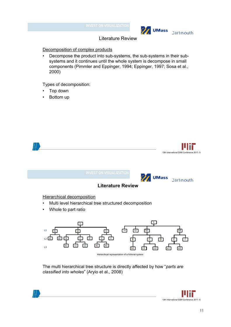
2 BACKGROUND ON DECOMPOSITION GUIDELINES Most of the system development projects consist of analysis of the system architecture. Product architecture is the arrangement of the product sub-functions and their interactions (Ulrich, 1995; Newcomb et al., 1998; Ulrich and Eppinger, 2000). A key feature of product architecture is the degree to which it is modular or integral (Sosa et al., 2000). Many products have a combination of modular and integrative architectures. These products have hybrid modular-integral architectures (Ulrich, 1995). Sosa et al. (2003) define modular architecture systems “as those whose design interfaces with other systems are clustered among a few physically adjacent systems”. Integrative architectural systems are those whose design interfaces “span all or most of the systems that comprise the product” (Sosa et al., 2003). The universal approach in the development of large engineering systems usually involves the decomposing of the complex product into sub-systems. These sub-systems are more likely to be complex as well and they are decomposed further. The process continues until the whole system, is decomposed into small components (Pimmler and Eppinger, 1994; Eppinger, 1997; Sosa et al., 2000). It has been assumed that there is a right way of system decomposition. Usually the decomposing process is driven by the researcher’s perception and knowledge to conceptually decompose the system into a multi-level hierarchy of interacting systems/components. It is assumed that people familiar with the system will decompose the system in an identical manner. This is very unlikely. It is more likely that two different teams will have different approaches to decompose a system into sub systems. There is a need to develop a common guideline in decomposing a system especially a complex system which has thousands of components. Complex systems are usually decomposed by using hierarchical structured decompositions. When decomposing a system it is advantageous to decide prior to decomposing process the complexity and the size of the subsystems (Ariyo et al., 2008). These decisions are important because it affects directly the architectural analysis results. The multi-level hierarchical tree structure is directly affected by how “parts (small chunks/sub-assemblies) are classified into wholes (big chunks/assemblies)” (Ariyo et al., 2008). For example, Figure 1shows the hierarchical decomposition of a fictional system, at three levels of decomposition, using two different
3
ABSTRACT
approaches to decompose the system. The fictional system (S) (whole) (Figure 1, left) has three, very well defined, sub systems (parts). Sub system 1 (S1) on the second level of decomposition is further decomposed into two more parts. Therefore S1 is a “part” for S, but a “whole” for a1 and a2. Figure 1 on the right represents the hierarchical tree for the same system but in which A1 and A2 replace S1. In this case it was decided that A1 and A2 should be “part” of the system S, being assumed that they represent important subassemblies of S.
Figure 1. Hierarchical representation of a fictional system
The guidelines for decomposing complex systems are meant to be used on top down decompositions. Top down decomposition of a complex system is done by gradually decomposing the system into chunks, major functions or major systems. The first level of decomposition is represented by these big chunks/functions/major systems. Each individual chunk/function/major system is decomposed in smaller chunks/sub functions or components/sub systems or components, forming the second level of decomposition and so on until the entire system is decomposed in components (Kossiakoff and Sweet, 2003). This stage represents the last level of decomposition which is formed of only components or individual functions. In our research we represent a real complex system as a Design Structure Matrix (DSM) at two levels of decomposition. The DSM is a popular method to analyse and organize a complex system (Browning, 2002; Sharman and Yassine, 2004). Thus far most published papers do not discuss the details of their decomposition approach. The common justification for decomposition is that is approved by experts. In our research we introduce three alternative means of decomposing a complex system. All three approaches are approved by systems experts. The three approaches are: assembly/disassembly decomposition, functional decomposition following the disciplines, and service based decomposition.
3 DECOMPOSITION GUIDELINES
3.1 Assembly decomposition We define the assembly decomposition as the decomposition in which big chunks are physically removed from a system. In assembly decomposition the first step is to visually inspect the system and observe the way components are attached: screws, hinges, etc. Second step is to identify the subassemblies that can be easily removed. Third step is to remove the subassemblies which most likely are represented by big chunks. Fourth step is to record them in a DSM. These big chunks represent the first level of decomposing a complex system. At this level if the system has HVAC/NOHAD/Air Systems, drives, controls, electrical components, those should be kept intact. If a small chunk seems to be attached to another keep these together. The goal is to identify if the smaller chunks are part of a bigger chunk. This decomposition type does not take in consideration functions. With each big chunk that is decomposed further a new level of decomposition is formed. In the process of decomposition the level of granularity, or the parts to whole ratio, need to be kept in mind.
3.2 Functional decomposition We define function decomposition as the decomposition in which the main functions of a system are first identified. Then these main sub functions are further decomposed in other sub functions if available or in the corresponding sub-assemblies, until the system is decomposed in single components. The first step for the functional decomposition of a complex system is to divide the system by its disciplines. We define discipline as a self-controlled sub system. For example: all the fans in a car form a discipline. The second step is to identify how these disciplines interact with each other and fill
4

in the DSM with the corresponding interaction between them. This will conclude the first level of decomposition. On the second level of decomposition each of these disciplines are decomposed in subsystems. This concludes the second level of decomposition. The decomposition continues until the whole system is decomposed into components.
3.3 Service based decomposition The service based decomposition relies directly on the corporations own system description in their service manual. A typical service manual consists of chapters on each high level sub system. All these chapters form the DSM for the first level of decomposition. Each of these chapters is further divided into sub section about the sub systems. All the sub sections form the DSM for the second level of decomposition. For example, a chapter in a vehicle’s service manual is dedicated to the Engine. That chapter is further divided into the following subsections: Exhaust, Controls, Electrical, Cooling, and Mechanical. In this case “engine” would be a module at the first level of decomposition. At the second level of decomposition, the engine module would be split into the five sub systems.
4 CASE STUDY To demonstrate how the above guidelines apply to complex systems, we decomposed a complex printing system by Xerox Corporation (Figure 2). The printing system has thousands of physical parts. It has very clearly defined subsystems and functions.
Figure 2. DocuColor™ 250
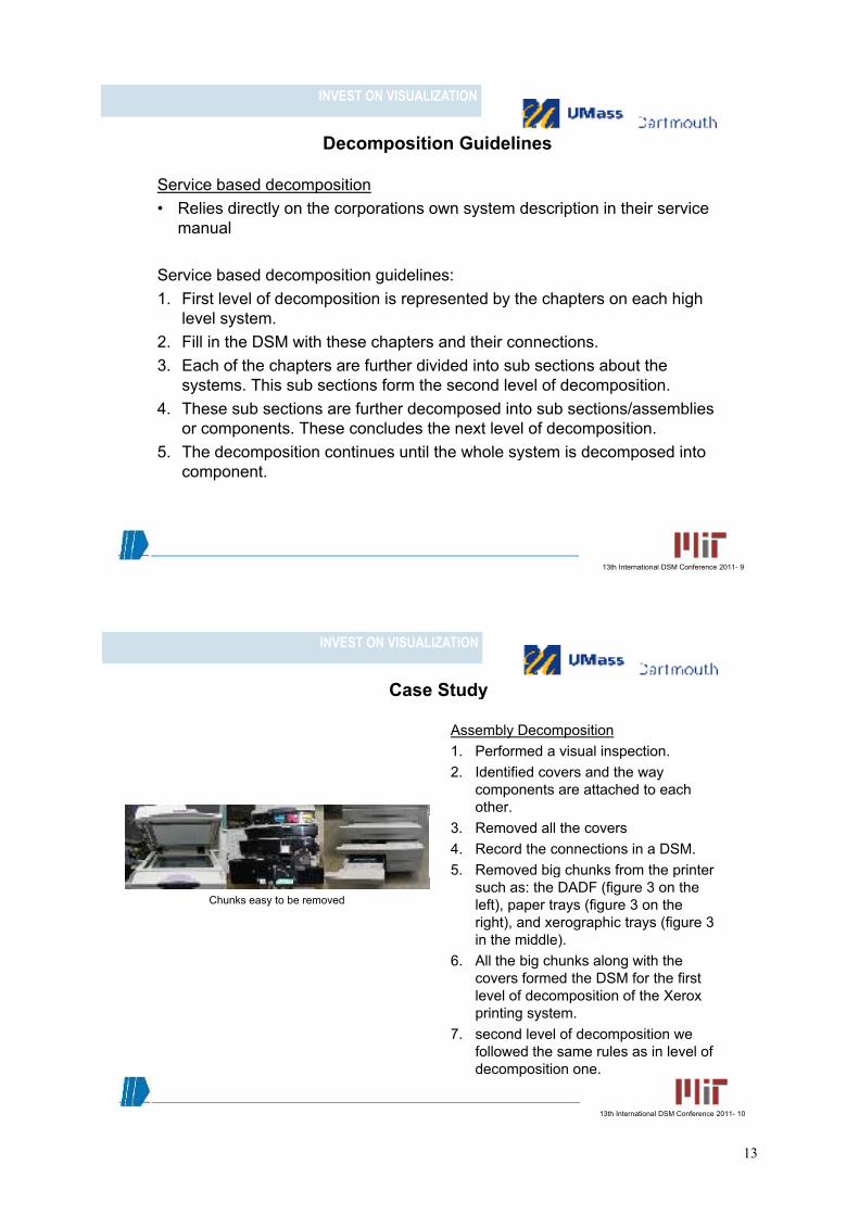
4.1 Assembly decomposition We followed the guidelines for assembly decomposition. We first performed a visual inspection. We identified covers and the way components are attached to each other. Most of the components, aside from the electrical and software connections, are either attached through screws or by hinges. We removed all the covers; we clustered them into one module and record the connections in a DSM. Then we removed big chunks from the printer such as: the DADF (Figure 3 on the left), paper trays (Figure 3 on the right), and xerographic trays (Figure 3 in the middle). All the big chunks along with the covers formed the DSM for the first level of decomposition of the Xerox printing system.
�Figure 3.Chunks easy to be removed
The first level of decomposition is 38 x 38 DSM, while the second level of decomposition is an 80 x 80 DSM (Figure 4). For the second level of decomposition we took each chunk and decompose it further in subsystems following the same rule as in level of decomposition one.
5

Figure 4. First and second level of decomposition (assembly decomposition)
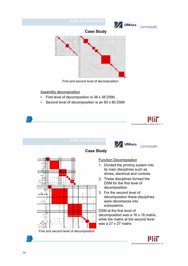
4.2 Function decomposition For this decomposition we followed the guidelines presented earlier. In the decomposition process of a complex system it is very important to have a naming nomenclature for functions/ components (Greer, 2003). In the first step of functional decomposition we divided the printing system into its main disciplines such as drives, electrical and controls. These disciplines formed the DSM for the first level of decomposition. For the second level DSM these disciplines were decompose into subsystems. The DSM at the first level of decomposition was a 16 x 16 matrix, while the matrix at the second level was a 27 x 27 matrix (Figure 5).
Figure 5. First and second level of decomposition (function decomposition)
4.3 Service based decomposition For the service based approach to decomposition, we simply looked at the way the systems are defined in its service manual. The chapter hierarchy in the manual provides a direct guideline as to how to decompose the system. . Some of the components in the second level of decomposition were not decompose further apart due to their simplicity and size. The first level of decomposition is represented by a 15 x 15 DSM (Figure 6). The second level of decomposition is represented by a 45 x 45 DSM (Figure 6).
Figure 6. First and second level of decomposition (service based)
6

5 ANALYSIS In this paper we provide a set of guidelines on decomposing a complex system which we then apply on a Xerox printing system. The decomposition of complex systems plays a big role in analyzing the product architecture. In our case study these can be easily noticed. The variation in the size of the DSM is quite prominent.
5.1 First level of decomposition DSM’s analysis The first type of decomposition, assembly decomposition, the DSM is represented by a 38 x 38 size matrix. The size of this DSM is more than twice larger than the other two decomposition types: function, 16 x16, and service, 15 x 15 matrixes. This difference was expected due to the fact that the chunks are not mapped to just one function or service components. By applying at glance the rules of the architecture of a product and by taking in consideration the fact that the chunks are not associated with just one function, we conclude that the printer has hybrid architecture when the assembly decomposition is used. The function and service decomposition just by the visual inspection also seem to have hybrid architecture although there are less connections outside the modules. The service decomposition DSM has five very dense buses among the following DSM entries: electrical/control, NOHAD, drives, cover and chassis. The function decomposition DSM seems to have four very distinctive (dense) buses among main drive, power unit, control unit and chassis. The assembly decomposition DSM has also four very populated buses: control unit, main drive, covers and chassis.
5.2 Second level of decomposition DSM’s analysis The product architecture is similar to the first level of decomposition, i.e. a hybrid architecture. Like in the first level of decomposition the DSM assembly decomposition is larger than the other two DSMs: almost twice larger that the service DSM and three times larger than the function DSM. It was expected that the DSM for the assembly decomposition to be much larger than the other two DSMs. The assembly decomposition DSM had only two dense buses: upper and lower chassis. The function and service decomposition DSM’s had three dense buses, main and control unit and drives and respectively power unit, main drive and chassis.
5.3 Decomposition guidelines and the case study analysis While these decomposition guidelines help guide the decomposition process, we came across a few observations. In the case of the function and service manual decomposition approaches, we had to make a few compromises during the decomposition process. For example in the service manual approach electrical and controls are treated as one for the first level of decomposition and separate from the components to which they belong to. Where, in reality these are serviced within the discipline that they belong to. During the process of decomposition we had to decide on the granularity of a series of subsystems among with their complexity so they are in line with all the other sub systems at that level of decomposition.
6 CONCLUSIONS AND FUTURE WORK It has been assumed that there is a right way of system decomposition. In this paper we introduced three distinct guidelines for decomposing a complex system. Then we applied each of these approaches to a Xerox printing system using a DSM to represent our system. For each of these approaches the DSM matrices varied from a 15 x 15 size matrix to a 38 x 38 size matrix for level one of decomposition, and from a 27 x 27 size matrix to a 80 x 80 size matrix for the second level of decomposition. Therefore is very important for the scope of architectural analysis to have a clear set of guidelines for decomposing a system. At glance, for both level of decomposition for all three types of decomposition the architecture of the printer seems to have hybrid architecture, i.e. a mix of modular and integral. Future work includes deciding what type of decomposition is most suitable for what type of application or system. Also a deeper level of decomposition should to be done and analyzed as well.
ACKNOWLEDGMENTS The authors would like to thank the Xerox Corporation for funding this work and for donating the printing systems used in this research.
7

REFERENCES Ariyo, O.O., Eckert, C.M., & Clarkson, P.J. (2008). Hierarchical decompositions for complex product
representation. In Proceedings of International Design Conference, Cavtat, May 2008. Browning, T. R. (2002). Process integration using the design structure matrix. Systems Engineering, 5,
180-193. Eppinger, S.D. (1997). A planning method for integration of large scale engineering systems. In
Proceedings of International Conference on Engineering Design. ICED’97, Vol. 1, Tampere, August (pp.199-204). Tampere University of Technology: Laboratory of Machine Design.
Greer, J. L. (2003). Enumerating the component space: first steps toward a design naming convention for mechanical parts. In Proceedings of ASME Design Engineering Technical Conferences and Computers and Information in Engineering Conference, Vol. 3b, Chicago, September (pp. 707-718).
Kossiakoff, A., & Sweet, W. (2003). Systems Enginnering Principles and Practice. Hoboken, NJ: John Wiley and Sons.
Newcomb, P.J., Bras, B., & Rosen, D.W. (1998). Implications of modularity on product design for the life cycle. ASME Journal of Mechanical Design, 120, 483-490.
Pimmler, T.U., & Eppinger, S.D (1994). Integration analysis of product decompositions. In Proceedings ASME Design Theory and Methodology Conference, Vol. 68, Minneapolis (pp. 343-351).
Sharman, D.M., & Yassine, A.A. (2004). Characterizing complex product architectures. System Engineering, 7, 35-60.
Sosa, M.E., Eppinger, S.D., & Rowles, C.M. (2000). Designing modular and integrative systems. In ASME International Conference on Design Theory and Methodology, Baltimore, September 2000.
Sosa, M.E., Eppinger, S.D., & Rowles, C.M. (2003). Identifying modular and integrative systems and their impact on design team interactions. ASME Journal of Mechanical Design, 125, 240-252.
Ulrich, K.T. (1995). The role of product architecture in manufacturing firm. Research Policy, 24, 419-440.
Ulrich, K.T., & Eppinger, S.D. (2000). Product Design and Development. New York: McGraw Hill.
Contact: Noemi Chiriac University of Massachusetts Dartmouth 285 Old Westport Road North Dartmouth, MA 02747-2300 USA e-mail: [email protected]
8
INVEST ON VISUALIZATION
Three Approaches to Complex SystemThree Approaches to Complex System Decomposition
Noemi Chiriac1, Katja Holtta Otto1,Dusan Lysy2 and Eun Suk Suh2
1University of Massachusetts Dartmouth, USAU e s ty o assac usetts a t out , US2Xerox Corporation, USA
INVEST ON VISUALIZATION
IndexIndex
• Introduction
• Literature Review
• Decomposition Guidelines
• Case StudyCase Study
• Analysis
• Conclusion and Future Work
A k l d t• Acknowledgements
• References
13th International DSM Conference 2011- 2
9

INVEST ON VISUALIZATION
IntroductionIntroduction
Literature review• Product architecture• Product architecture• Decomposition• Hierarchical decomposition• DSM
www.densitykatrina.com
• DSM
Guidelines to decompose a complex system• Assembly decompositiony p• Functional decomposition• Service based decomposition www.hallsource.com
Case Study• Xerox printing system at two levels of decomposition
AnalysisAnalysis• DSM• Product architecture typology
G id li
www.xerox.com
13th International DSM Conference 2011- 3
• Guidelines
INVEST ON VISUALIZATION
Literature ReviewLiterature Review
Product architecture• An arrangement of the product sub functions and their interactions• An arrangement of the product sub functions and their interactions
(Ulrich, 1995; Newcomb et al., 1998; Ulrich and Eppinger, 2000).
T l f d t hit tTypology of product architecture:• Modular architecture• Integrative architecturesg• Hybrid architectures (Ulrich, 1995; Sosa et al., 2003)
13th International DSM Conference 2011- 4
10
INVEST ON VISUALIZATION
Literature ReviewLiterature Review
Decomposition of complex products• Decompose the product into sub systems the sub systems in their sub• Decompose the product into sub-systems, the sub-systems in their sub-
systems and it continues until the whole system is decompose in small components (Pimmler and Eppinger, 1994; Eppinger, 1997; Sosa et al., 2000)2000)
Types of decomposition:• Top down• Bottom up
13th International DSM Conference 2011- 5
INVEST ON VISUALIZATION
Literature ReviewLiterature Review
Hierarchical decomposition• Multi level hierarchical tree structured decomposition• Multi level hierarchical tree structured decomposition• Whole to part ratio
The multi hierarchical tree structure is directly affected by how “parts are
Hierarchical representation of a fictional system
classified into wholes” (Aryio et al., 2008)
13th International DSM Conference 2011- 6
11

INVEST ON VISUALIZATION
Decomposition GuidelinesDecomposition Guidelines
Assembly decomposition• Big chunks are physically removed from a system• Big chunks are physically removed from a system
Assembly decomposition guidelines:1. Get familiar with the system by visual inspection2. Identify subassemblies that can easily be removed3. Remove the big chunks/assemblies4. Record them in a DSM. These concludes the first level of decomposition. 5. At this level drives, controls, electrical components, air systems should be kept
intact.6. Decompose each chunk further keeping in mind the complexity of the chunks
belonging to that level of decomposition
13th International DSM Conference 2011- 7
INVEST ON VISUALIZATION
Decomposition GuidelinesDecomposition Guidelines
Functional decomposition • is the decomposition in which a system is decomposed by its main• is the decomposition in which a system is decomposed by its main
functions, then in sub-functions of the main function
F ti l D iti id liFunctional Decomposition guidelines:1. Divide the system by its disciplines (self controlled sub system)2. Identify the material, energy and signal connections between these y gy g
disciplines3. Fill in the DSM with the disciplines and their connections. This concludes
the first level of decomposition. p4. Each of the above disciplines are decompose further into sub
systems/components5 These concludes the second level of decomposition5. These concludes the second level of decomposition.6. The decomposition continues until the whole systems is at the component
level.
13th International DSM Conference 2011- 8
12
INVEST ON VISUALIZATION
Decomposition GuidelinesDecomposition Guidelines
Service based decomposition• Relies directly on the corporations own system description in their service• Relies directly on the corporations own system description in their service
manual
S i b d d iti id liService based decomposition guidelines:1. First level of decomposition is represented by the chapters on each high
level system.2. Fill in the DSM with these chapters and their connections.3. Each of the chapters are further divided into sub sections about the
systems. This sub sections form the second level of decomposition.y p4. These sub sections are further decomposed into sub sections/assemblies
or components. These concludes the next level of decomposition.5 The decomposition continues until the whole system is decomposed into5. The decomposition continues until the whole system is decomposed into
component.
13th International DSM Conference 2011- 9
INVEST ON VISUALIZATION
Case StudyCase Study
Assembly Decomposition 1. Performed a visual inspection.1. Performed a visual inspection.2. Identified covers and the way
components are attached to each other.
3. Removed all the covers4. Record the connections in a DSM.5. Removed big chunks from the printer g p
such as: the DADF (figure 3 on the left), paper trays (figure 3 on the right), and xerographic trays (figure 3 in the middle)
Chunks easy to be removed
in the middle). 6. All the big chunks along with the
covers formed the DSM for the first level of decomposition of the Xeroxlevel of decomposition of the Xerox printing system.
7. second level of decomposition we followed the same rules as in level of
13th International DSM Conference 2011- 10
decomposition one.
13
INVEST ON VISUALIZATION
Case StudyCase Study
First and second level of decomposition
Assembly decomposition• First level of decomposition is 38 x 38 DSM, • Second level of decomposition is an 80 x 80 DSM
13th International DSM Conference 2011- 11
INVEST ON VISUALIZATION
Case StudyCase Study
Function Decomposition1 Divided the printing system into1. Divided the printing system into
its main disciplines such as drives, electrical and controls.
2 These disciplines formed the2. These disciplines formed the DSM for the first level of decomposition
3 F th d l l f3. For the second level of decomposition these disciplines were decompose into subsystemssubsystems.
DSM at the first level of decomposition was a 16 x 16 matrix, while the matrix at the second levelwhile the matrix at the second level was a 27 x 27 matrix
First and second level of decomposition
13th International DSM Conference 2011- 12
First and second level of decomposition
14

INVEST ON VISUALIZATION
Case StudyCase Study
Service based decomposition1 Looked at the way the systems1. Looked at the way the systems
are defined in its service manual2. The chapters included in the
service manual were used to fillservice manual were used to fill in the DSM of the first level of decomposition (15 x 15 matrix)
3 Th b b ti f th3. The sub subsections of the chapters formed the DSM at the second level of decomposition (45 x 45 matrix)(45 x 45 matrix)
First and second level of decompositionFirst and second level of decomposition
13th International DSM Conference 2011- 13
INVEST ON VISUALIZATION
AnalysisAnalysis
AnalysisFirst Level of DecompositionFirst Level of DecompositionThe size of the DSM, at the first level of decomposition, for the assembly decomposition is more than double in size compared to the other decomposition approachesdecomposition approaches.
All three DSMs at glance seem to have a hybrid architecture although an official analysis has not been done.
All three decompositions have distinctive busses: assembly and function p ydecomposition have four while the assembly decomposition has five.
13th International DSM Conference 2011- 14
15

INVEST ON VISUALIZATION
AnalysisAnalysis
AnalysisSecond Level of DecompositionSecond Level of DecompositionAs in the first level of decomposition the assembly DSM’s size is twice as large than the service DSM and three times larger than the function decompositiondecomposition.
The architecture of the DSMs for all three types of decomposition also seems to be hybrid as in the first level of decomposition.
While the assembly decomposition had only two distinctive busses the other y p ytwo decomposition types had three distinctive busses.
The guidelines were easy to followThe guidelines were easy to follow.
13th International DSM Conference 2011- 15
INVEST ON VISUALIZATION
ConclusionConclusion
In this paper we introduced a set of guidelines for three different approaches on decomposing a complex systemon decomposing a complex system.
Then we applied each of these approaches to a Xerox printing system using a DSM to represent our systema DSM to represent our system.
The guidelines introduced were easy to follow and to be applied to all three types of decomposition.
13th International DSM Conference 2011- 16
16

INVEST ON VISUALIZATION
Future WorkFuture Work
In the future, we intend to analyse the printer architecture in more depth to determine what types of architecture each type of decomposition has.
Also a third level of decomposition is going to be done and analysed as well.
13th International DSM Conference 2011- 17
17