Embed Size (px)
Citation preview
Three Case Studies of High Reliability Power Systems
Keene M. Matsuda, P.E.Senior Member IEEE
IEEE/PES Distinguished [email protected]
Buenos Aires, Argentina
June 25 & 26, 2009
Three Case Studies of High Reliability Power Systems
Keene M. Matsuda, P.E.Senior Member IEEE
IEEE/PES Distinguished [email protected]
Buenos Aires, Argentina
June 25 & 26, 2009
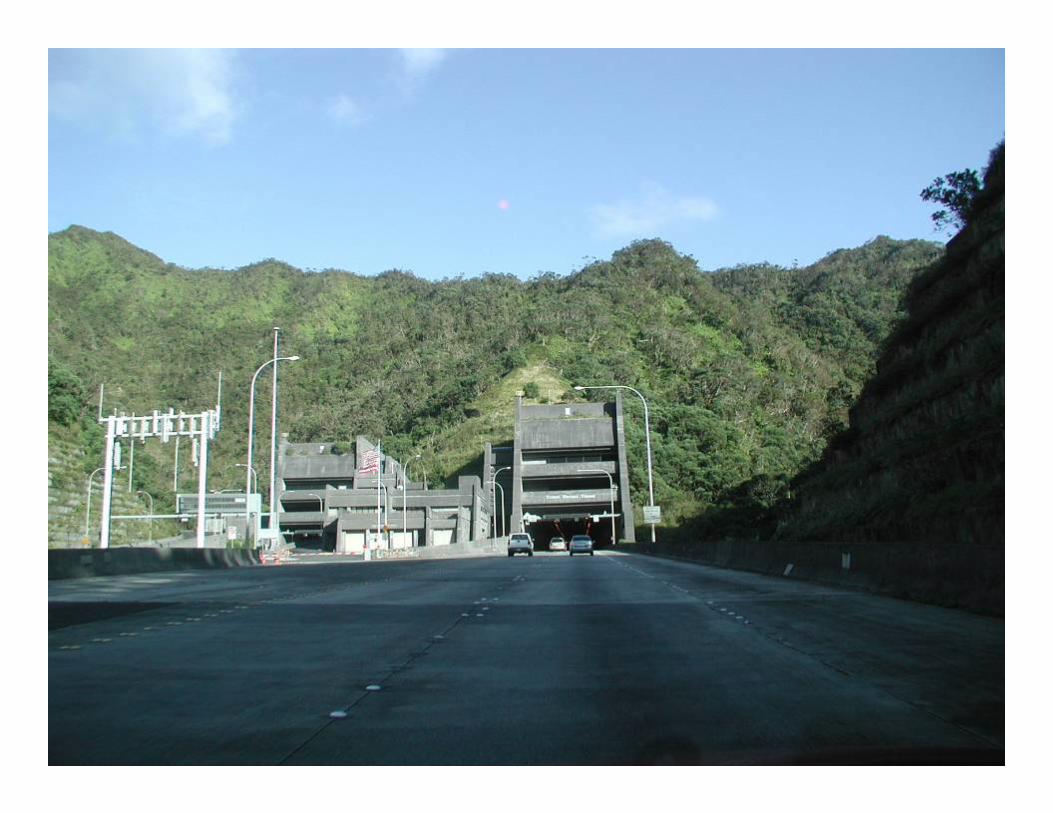
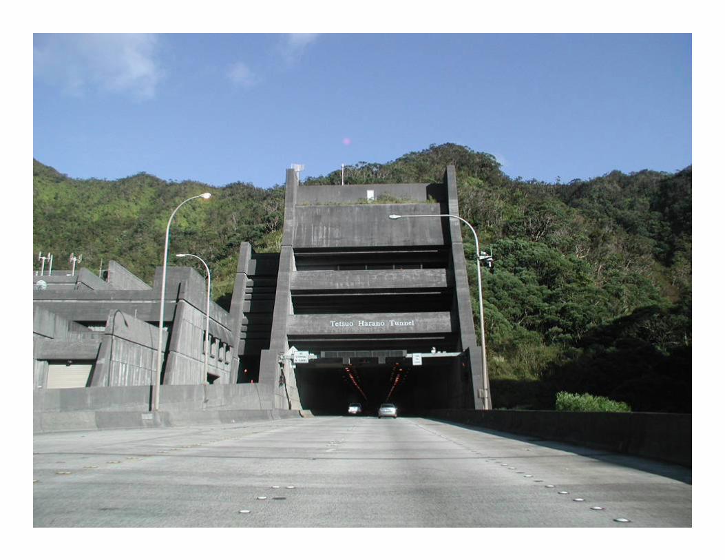
Project No. 1: H-3 TunnelProject No. 1: H-3 Tunnel
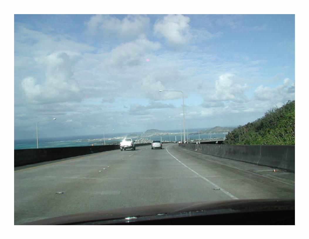
1.6 km (1 mile) long, twin-bore tunnel thru Koolau mountainsPart of 26-km highway in Honolulu, HawaiiTunnel connects Halawa valley to west and Haiku valley to eastCost: $1.3 billion (US) = 90% from FHWA + 10% from HDOT
1.6 km (1 mile) long, twin-bore tunnel thru Koolau mountainsPart of 26-km highway in Honolulu, HawaiiTunnel connects Halawa valley to west and Haiku valley to eastCost: $1.3 billion (US) = 90% from FHWA + 10% from HDOT
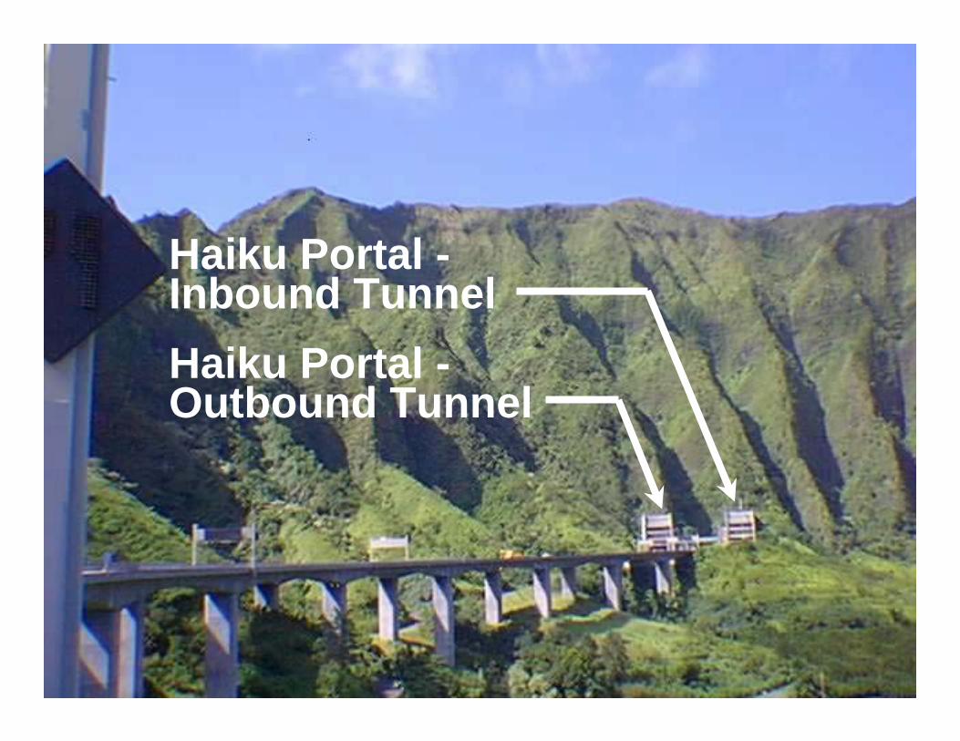
Photo: Haiku PortalPhoto: Haiku Portal
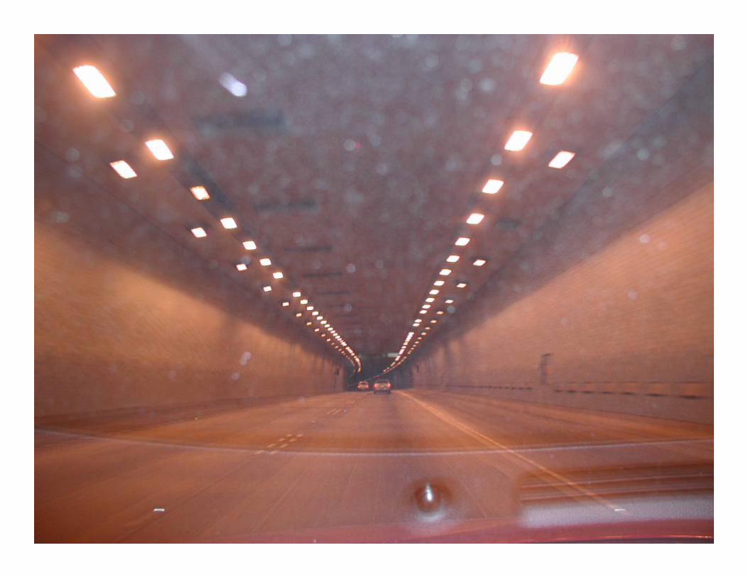
Haiku Portal -Inbound TunnelHaiku Portal -Outbound Tunnel
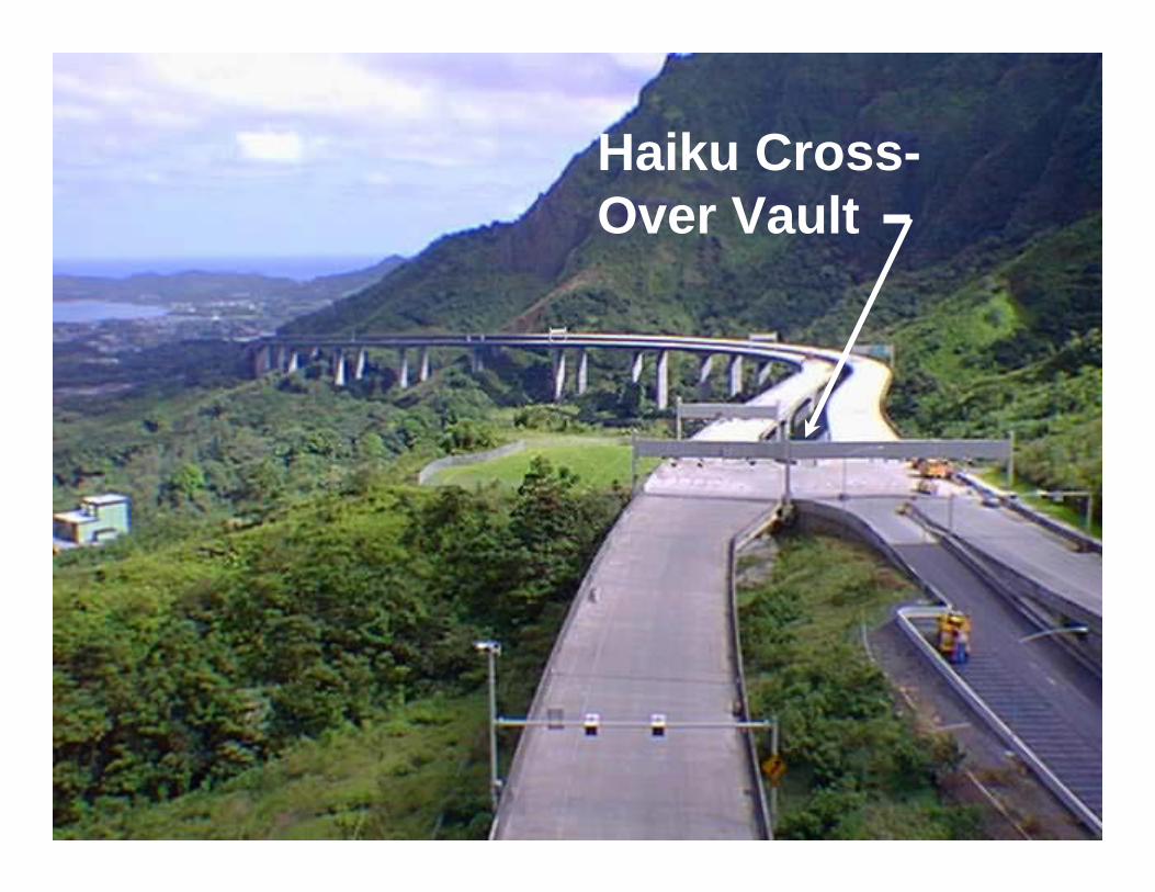
Photo: Haiku Cross-OverPhoto: Haiku Cross-OverHaiku Cross-Over Vault
4 Sources of power4 Sources of power
For high reliability, 4 sources:2 utility HV transmission circuits1-500 kW emergency generatorNumerous UPS and battery/inverter units
For high reliability, 4 sources:2 utility HV transmission circuits1-500 kW emergency generatorNumerous UPS and battery/inverter units
Utility power sourceUtility power source
2-46 kV HECO transmission lines for high reliabilityRadial circuits terminate at portal substations: Halawa & HaikuSeparate substations for redundancy10 MVA, 46-12.47 kV transformer, fully sized for redundancy
2-46 kV HECO transmission lines for high reliabilityRadial circuits terminate at portal substations: Halawa & HaikuSeparate substations for redundancy10 MVA, 46-12.47 kV transformer, fully sized for redundancy
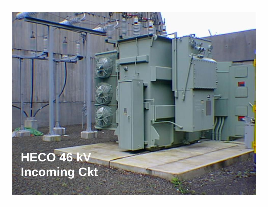
Photo: TransformerPhoto: Transformer
HECO 46 kVIncoming Ckt
Slide 8
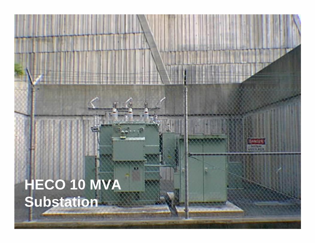
Photo: TransformerPhoto: Transformer
HECO 10 MVASubstation
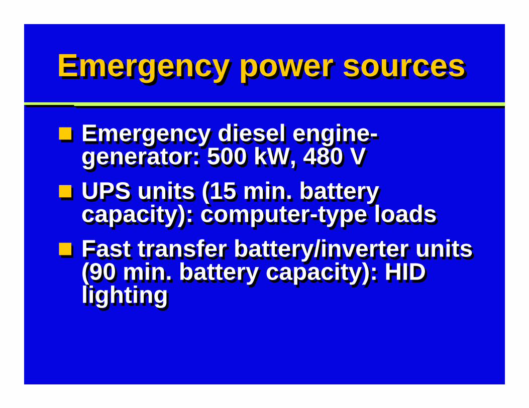
Emergency power sourcesEmergency power sources
Emergency diesel engine-generator: 500 kW, 480 VUPS units (15 min. battery capacity): computer-type loadsFast transfer battery/inverter units (90 min. battery capacity): HID lighting
Emergency diesel engine-generator: 500 kW, 480 VUPS units (15 min. battery capacity): computer-type loadsFast transfer battery/inverter units (90 min. battery capacity): HID lighting
Slide 10
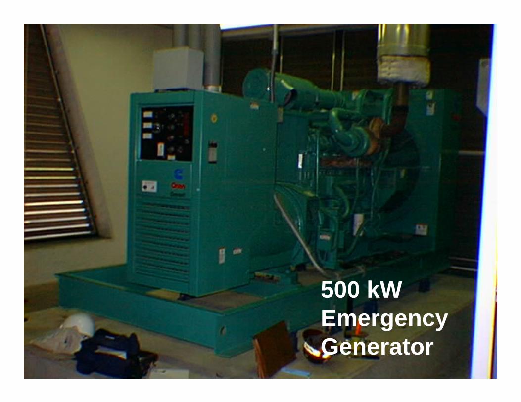
Photo: TransformerPhoto: Transformer
500 kWEmergencyGenerator
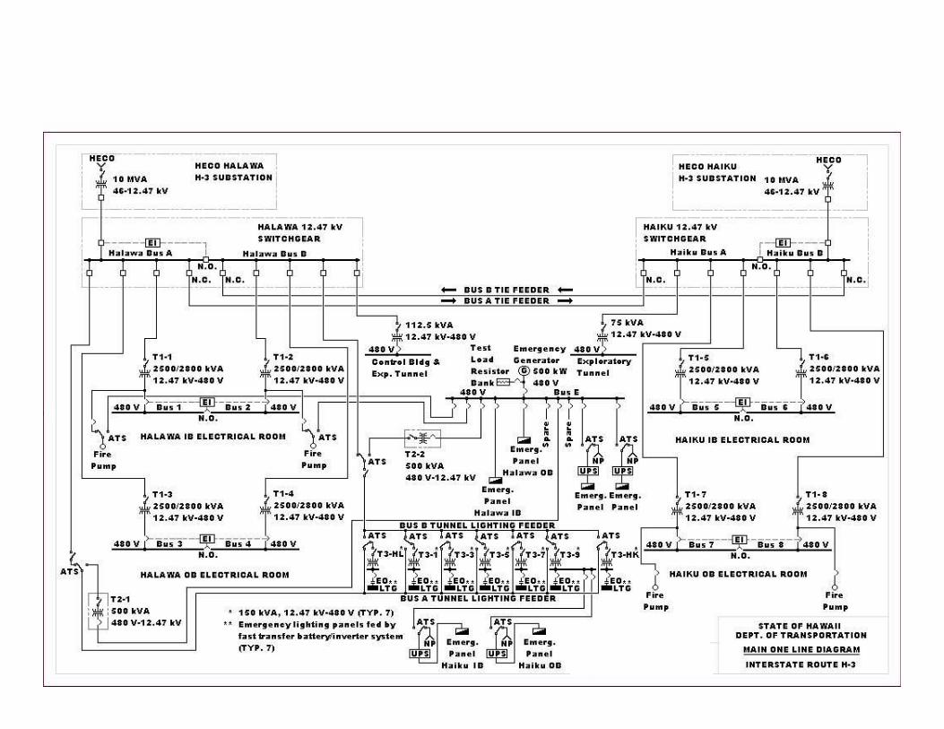
Main One Line DiagramMain One Line Diagram
Slide 12
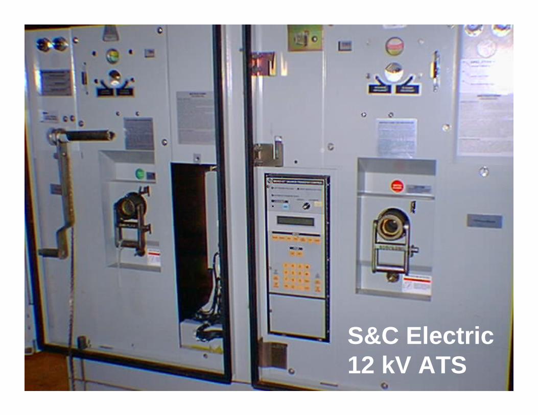
Main One Line DiagramMain One Line Diagram
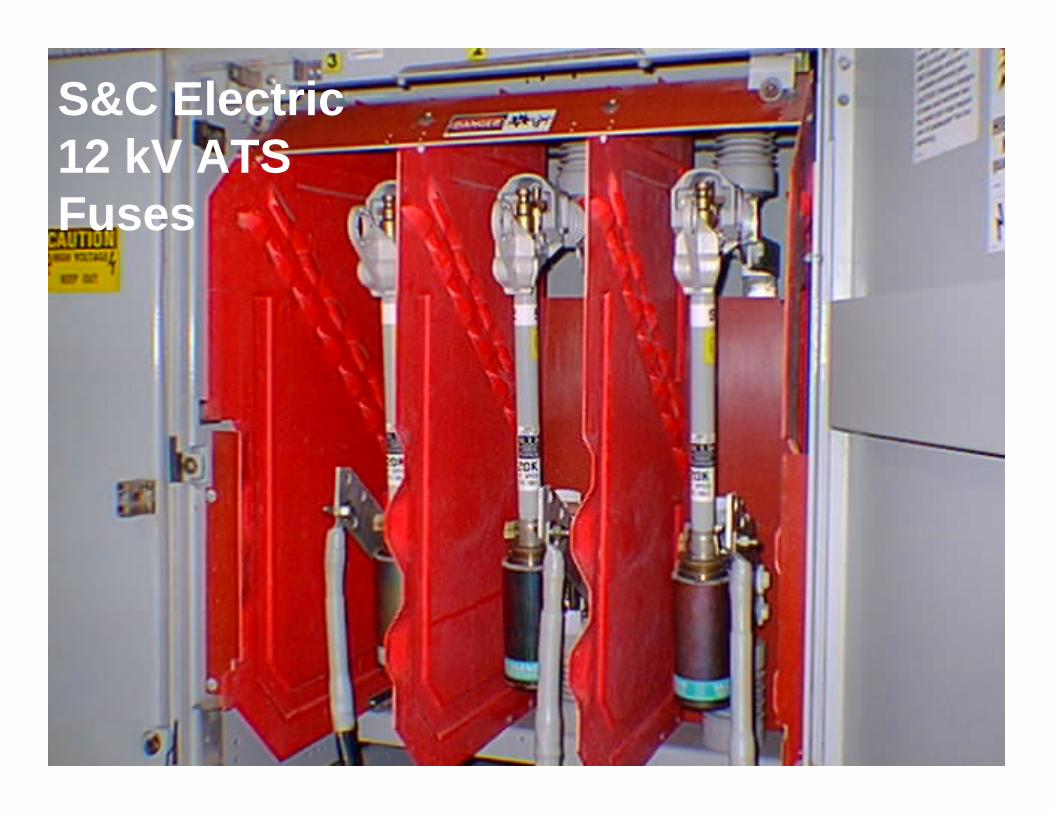
S&C Electric12 kV ATS
Slide 13
Main One Line DiagramMain One Line DiagramS&C Electric12 kV ATSFuses
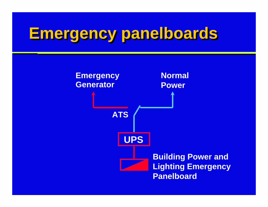
Emergency panelboardsEmergency panelboards
EmergencyGenerator
Normal Power
ATS
UPS
Building Power and Lighting Emergency Panelboard
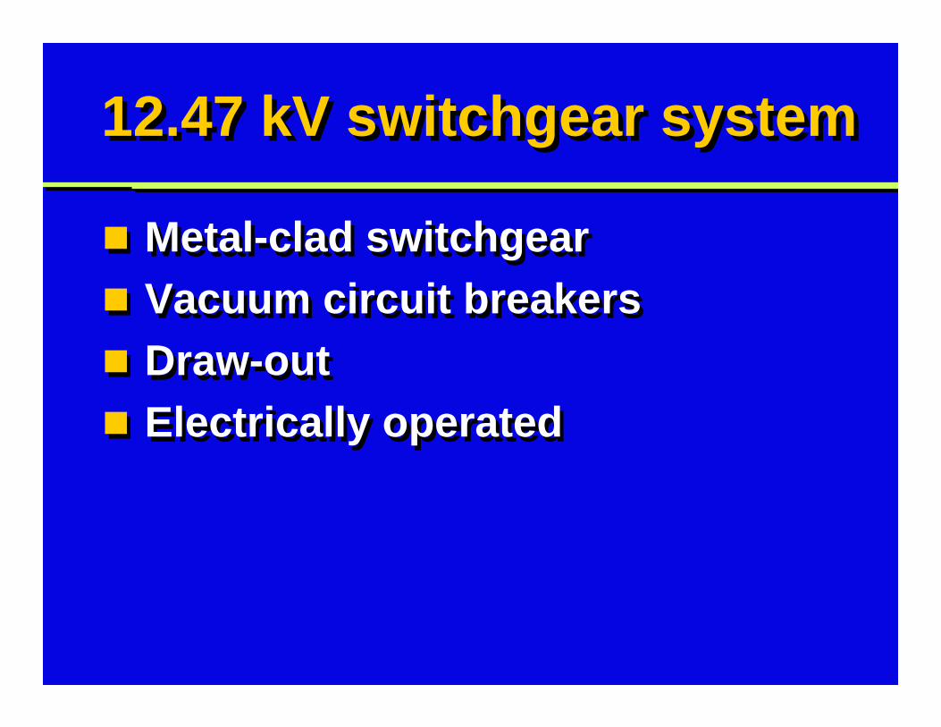
12.47 kV switchgear system12.47 kV switchgear system
Metal-clad switchgearVacuum circuit breakersDraw-outElectrically operated
Metal-clad switchgearVacuum circuit breakersDraw-outElectrically operated
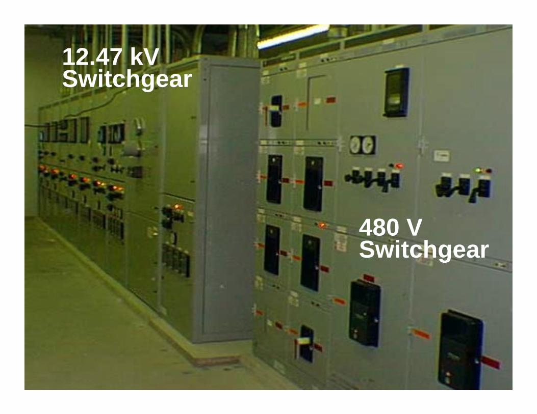
Photo: SwitchgearPhoto: Switchgear12.47 kV Switchgear
480 V Switchgear
Slide 17
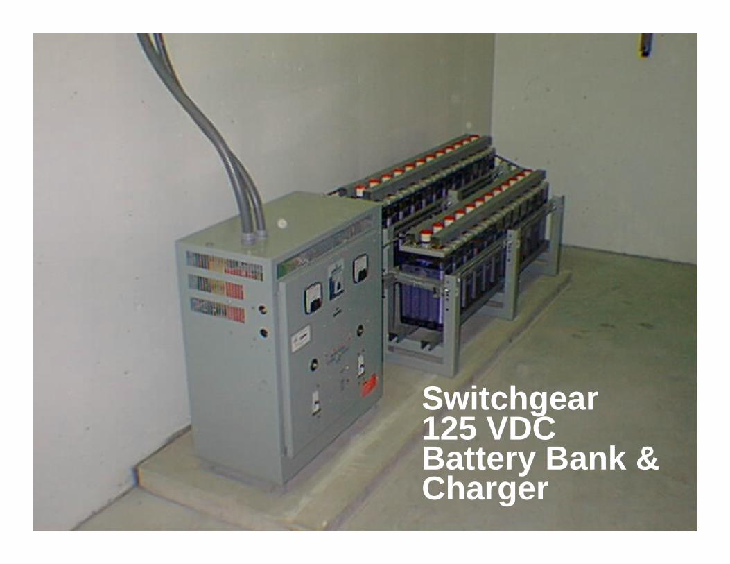
Photo: SwitchgearPhoto: Switchgear
Switchgear125 VDCBattery Bank &Charger
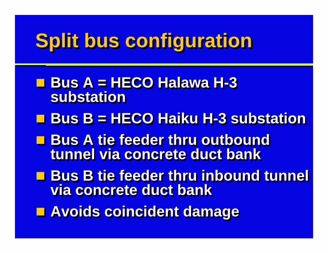
Split bus configurationSplit bus configuration
Bus A = HECO Halawa H-3 substationBus B = HECO Haiku H-3 substationBus A tie feeder thru outbound tunnel via concrete duct bankBus B tie feeder thru inbound tunnel via concrete duct bankAvoids coincident damage
Bus A = HECO Halawa H-3 substationBus B = HECO Haiku H-3 substationBus A tie feeder thru outbound tunnel via concrete duct bankBus B tie feeder thru inbound tunnel via concrete duct bankAvoids coincident damage
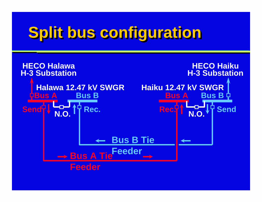
Split bus configurationSplit bus configuration
Bus A Bus ABus B Bus B
HECO HalawaH-3 Substation
HECO HaikuH-3 Substation
Halawa 12.47 kV SWGR Haiku 12.47 kV SWGR
N.O. N.O.
Bus B Tie FeederBus A Tie
Feeder
Send SendRec. Rec.
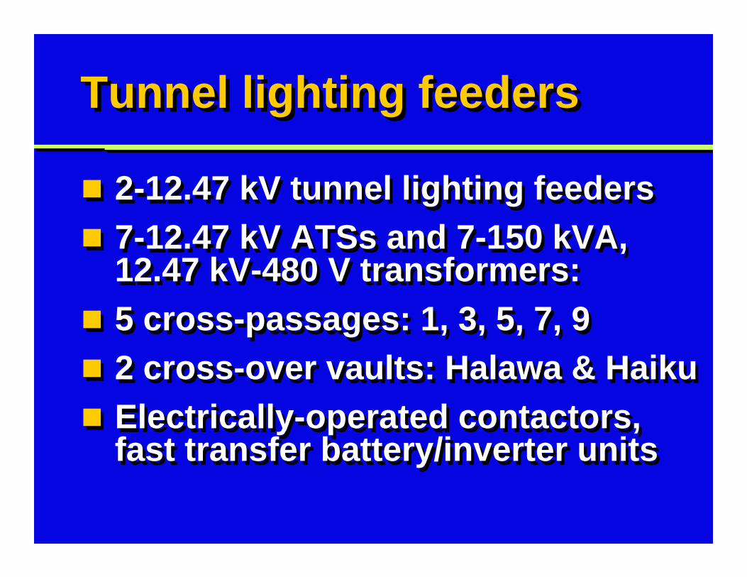
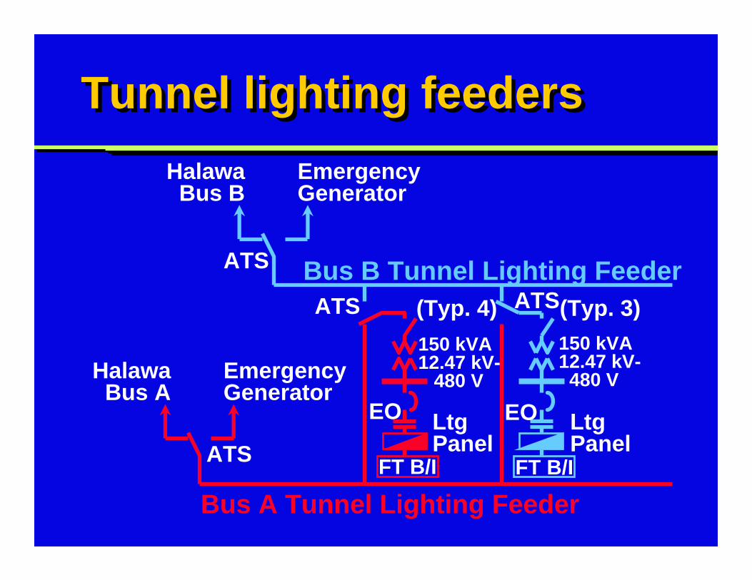
Tunnel lighting feedersTunnel lighting feeders
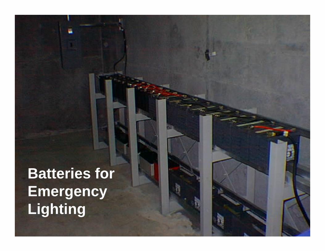
2-12.47 kV tunnel lighting feeders7-12.47 kV ATSs and 7-150 kVA, 12.47 kV-480 V transformers:5 cross-passages: 1, 3, 5, 7, 92 cross-over vaults: Halawa & HaikuElectrically-operated contactors, fast transfer battery/inverter units
2-12.47 kV tunnel lighting feeders7-12.47 kV ATSs and 7-150 kVA, 12.47 kV-480 V transformers:5 cross-passages: 1, 3, 5, 7, 92 cross-over vaults: Halawa & HaikuElectrically-operated contactors, fast transfer battery/inverter units
Slide 21
Photo: TransformerPhoto: Transformer
Batteries forEmergencyLighting
Tunnel lighting feedersTunnel lighting feeders
150 kVA12.47 kV-
480 V
150 kVA12.47 kV-480 V
EO EO
ATS ATS
HalawaBus B
EmergencyGenerator
ATS
ATS
HalawaBus A
EmergencyGenerator
Bus B Tunnel Lighting Feeder
Bus A Tunnel Lighting Feeder
(Typ. 4) (Typ. 3)
LtgPanel
FT B/I
LtgPanel
FT B/I
Slide 23
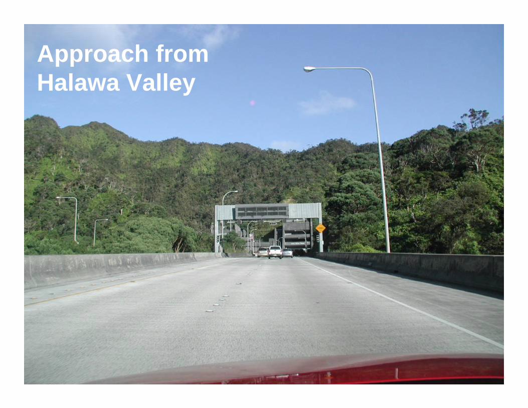
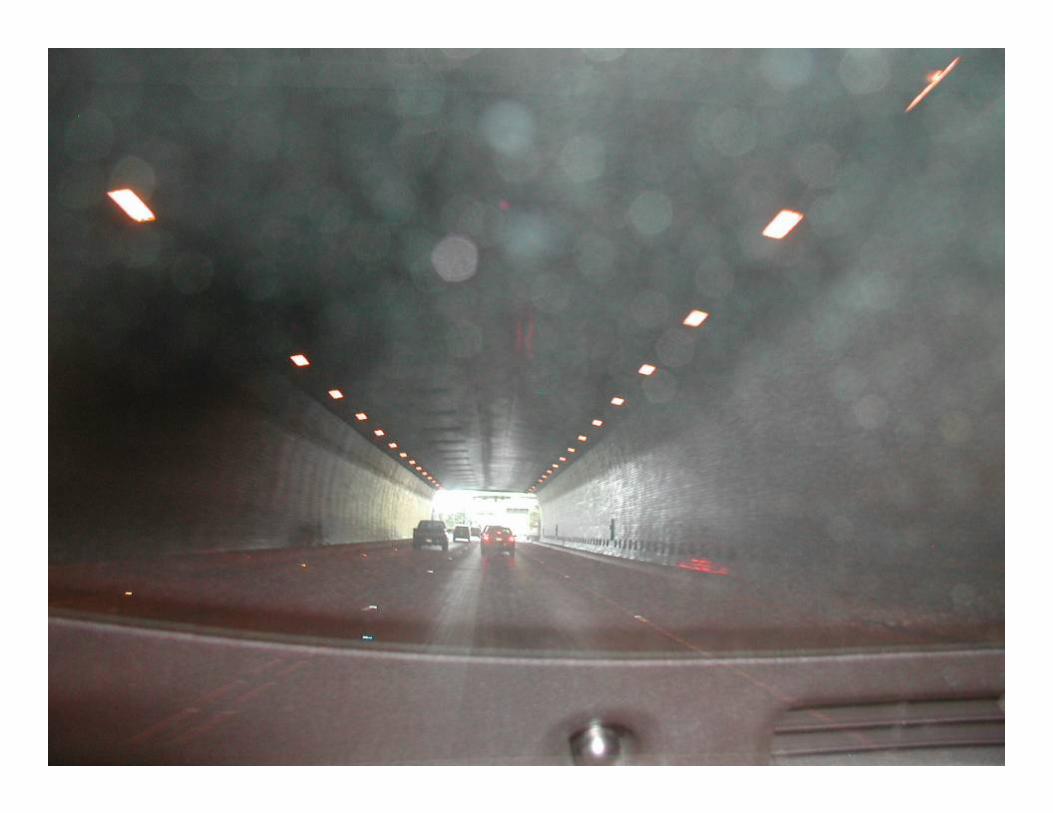
Photo: Haiku Cross-OverPhoto: Haiku Cross-OverApproach fromHalawa Valley
Slide 24
Photo: Haiku Cross-OverPhoto: Haiku Cross-Over
Slide 25
Photo: Haiku Cross-OverPhoto: Haiku Cross-Over
Slide 26
Photo: Haiku Cross-OverPhoto: Haiku Cross-Over
Slide 27
Photo: Haiku Cross-OverPhoto: Haiku Cross-Over
Slide 28
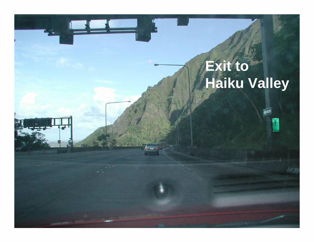
Photo: Haiku Cross-OverPhoto: Haiku Cross-OverExit to Haiku Valley
Slide 29
Photo: Haiku Cross-OverPhoto: Haiku Cross-Over
12.47 kV swgr interlocking12.47 kV swgr interlocking
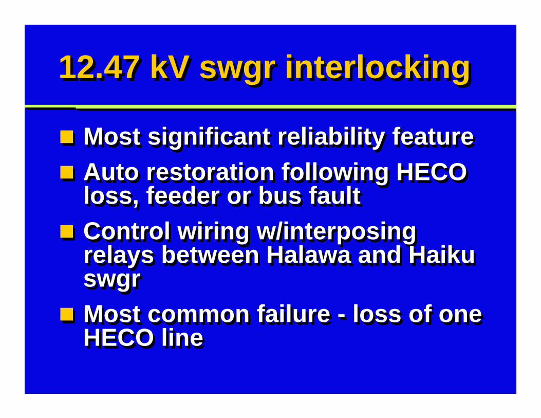
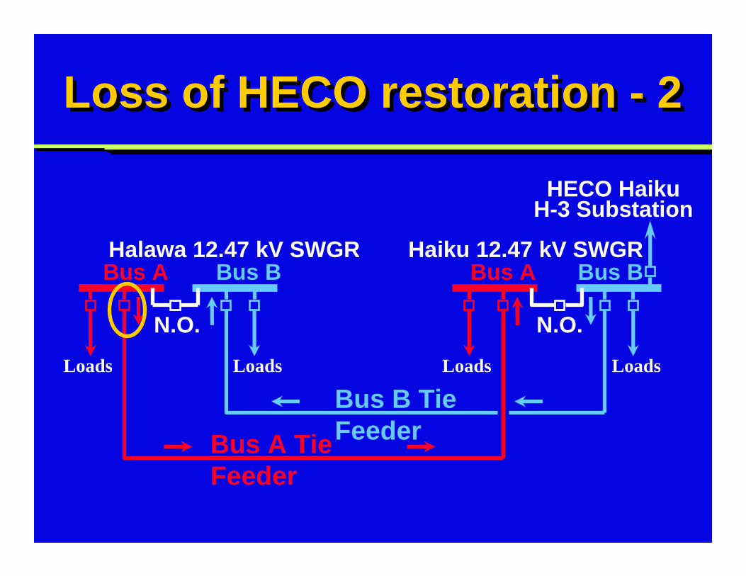
Most significant reliability featureAuto restoration following HECO loss, feeder or bus faultControl wiring w/interposing relays between Halawa and Haiku swgrMost common failure - loss of one HECO line
Most significant reliability featureAuto restoration following HECO loss, feeder or bus faultControl wiring w/interposing relays between Halawa and Haiku swgrMost common failure - loss of one HECO line
Slide 31
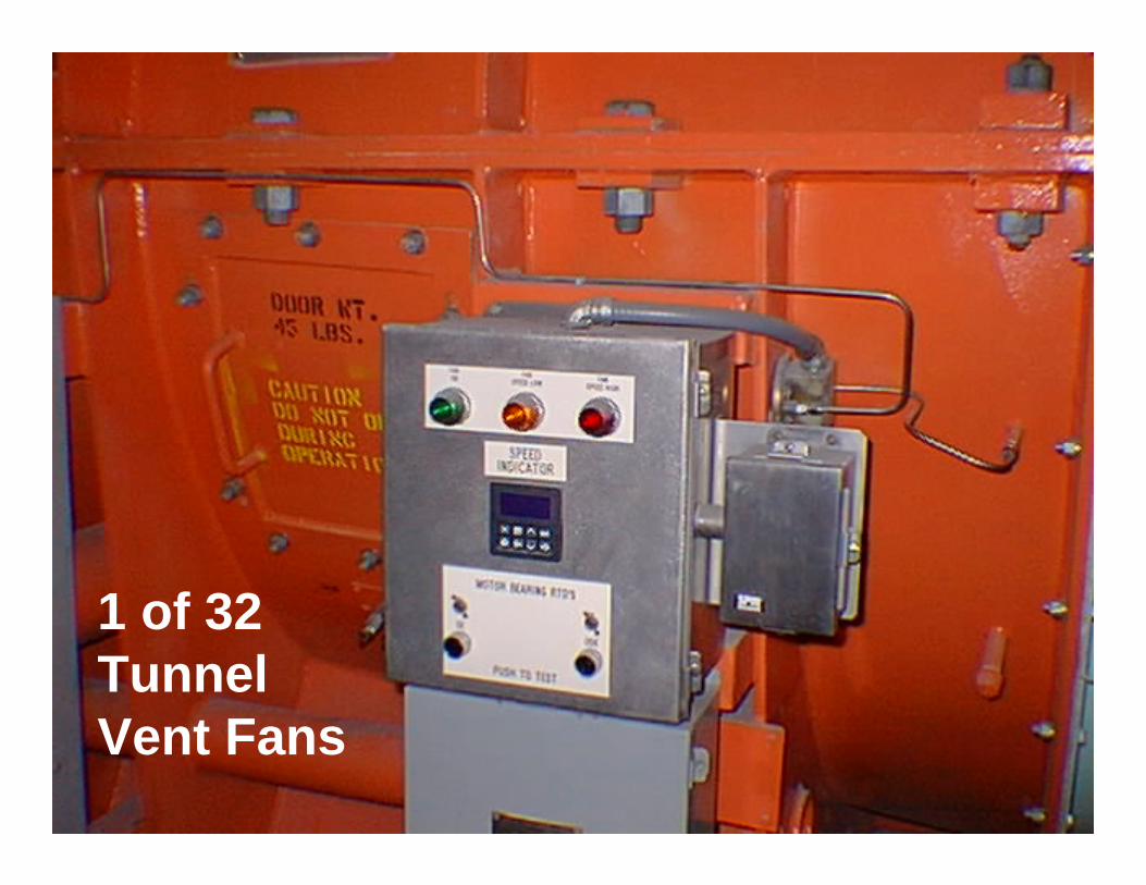
Photo: TransformerPhoto: Transformer
1 of 32 TunnelVent Fans
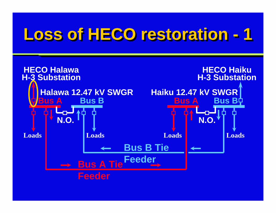
Loss of HECO restoration - 1Loss of HECO restoration - 1
Bus A Bus ABus B Bus B
HECO HalawaH-3 Substation
HECO HaikuH-3 Substation
Halawa 12.47 kV SWGR Haiku 12.47 kV SWGR
N.O. N.O.
Bus B Tie FeederBus A Tie
Feeder
LoadsLoads Loads Loads
Bus A Bus ABus B Bus B
HECO HaikuH-3 Substation
Haiku 12.47 kV SWGR
N.O. N.O.
Bus B Tie FeederBus A Tie
Feeder
LoadsLoads Loads Loads
Loss of HECO restoration - 2Loss of HECO restoration - 2
Halawa 12.47 kV SWGR
Bus A Bus ABus B Bus B
HECO HaikuH-3 Substation
N.O. N.O.
Bus B Tie FeederBus A Tie
Feeder
LoadsLoads Loads Loads
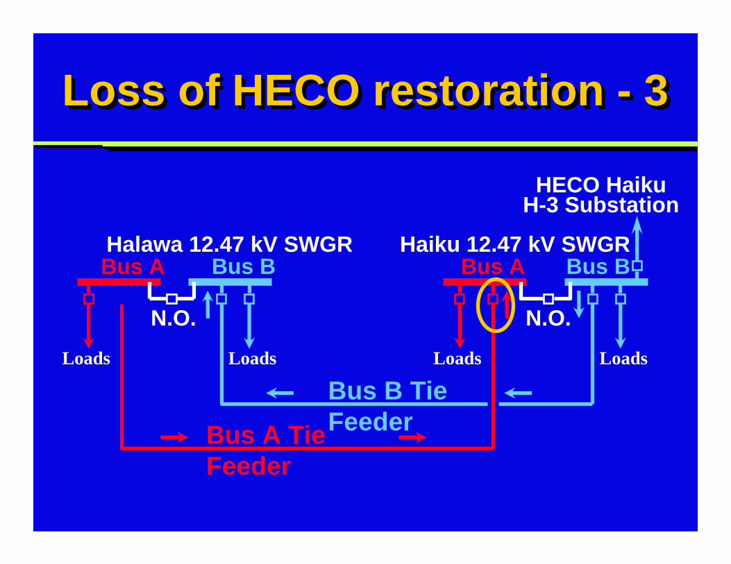
Loss of HECO restoration - 3Loss of HECO restoration - 3
Halawa 12.47 kV SWGR Haiku 12.47 kV SWGR
Bus A Bus ABus B Bus B
N.O. N.O.
Bus B Tie FeederBus A Tie
Feeder
LoadsLoads Loads Loads
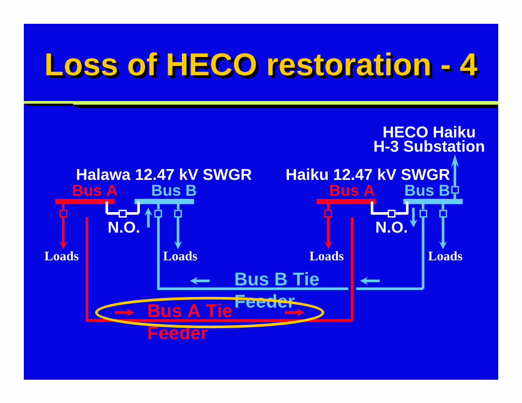
Loss of HECO restoration - 4Loss of HECO restoration - 4
Halawa 12.47 kV SWGR
HECO HaikuH-3 Substation
Haiku 12.47 kV SWGR
Bus A Bus ABus B Bus B
N.O. N.O.
Bus B Tie Feeder
LoadsLoads Loads Loads
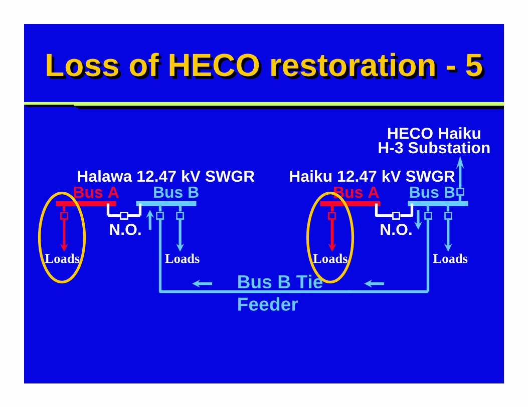
Loss of HECO restoration - 5Loss of HECO restoration - 5
Halawa 12.47 kV SWGR
HECO HaikuH-3 Substation
Haiku 12.47 kV SWGR
Bus A Bus ABus B Bus B
HECO HaikuH-3 Substation
N.O. N.O.
Bus B Tie Feeder
LoadsLoads Loads LoadsX X
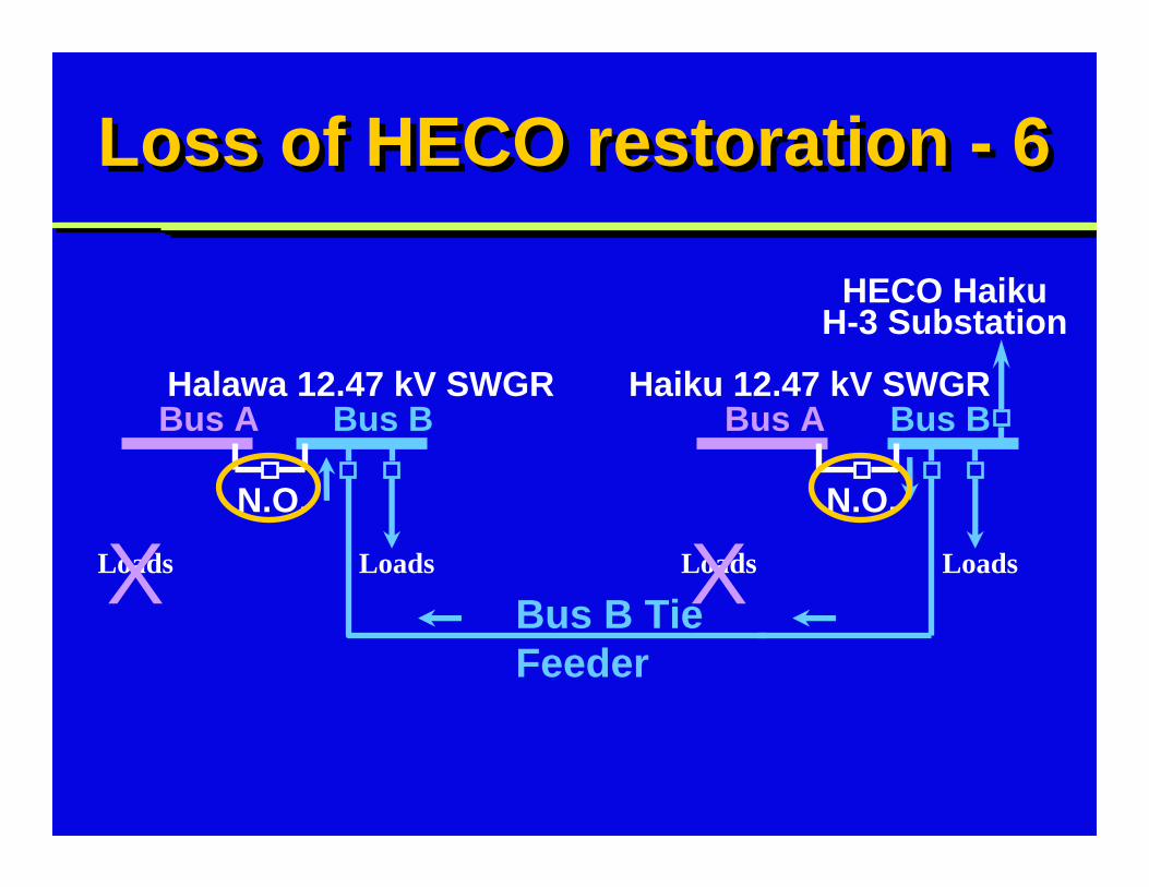
Loss of HECO restoration - 6Loss of HECO restoration - 6
Halawa 12.47 kV SWGR Haiku 12.47 kV SWGR
Bus A Bus ABus B Bus B
HECO HaikuH-3 Substation
Closed Closed
Bus B Tie Feeder
LoadsLoads Loads LoadsX X
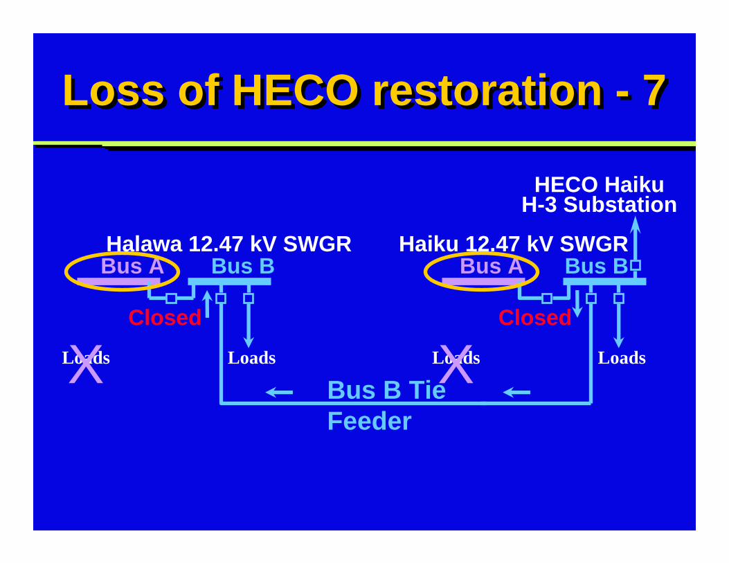
Loss of HECO restoration - 7Loss of HECO restoration - 7
Halawa 12.47 kV SWGR Haiku 12.47 kV SWGR
Bus A Bus ABus B Bus B
Closed Closed
Bus B Tie Feeder
LoadsLoads Loads Loads
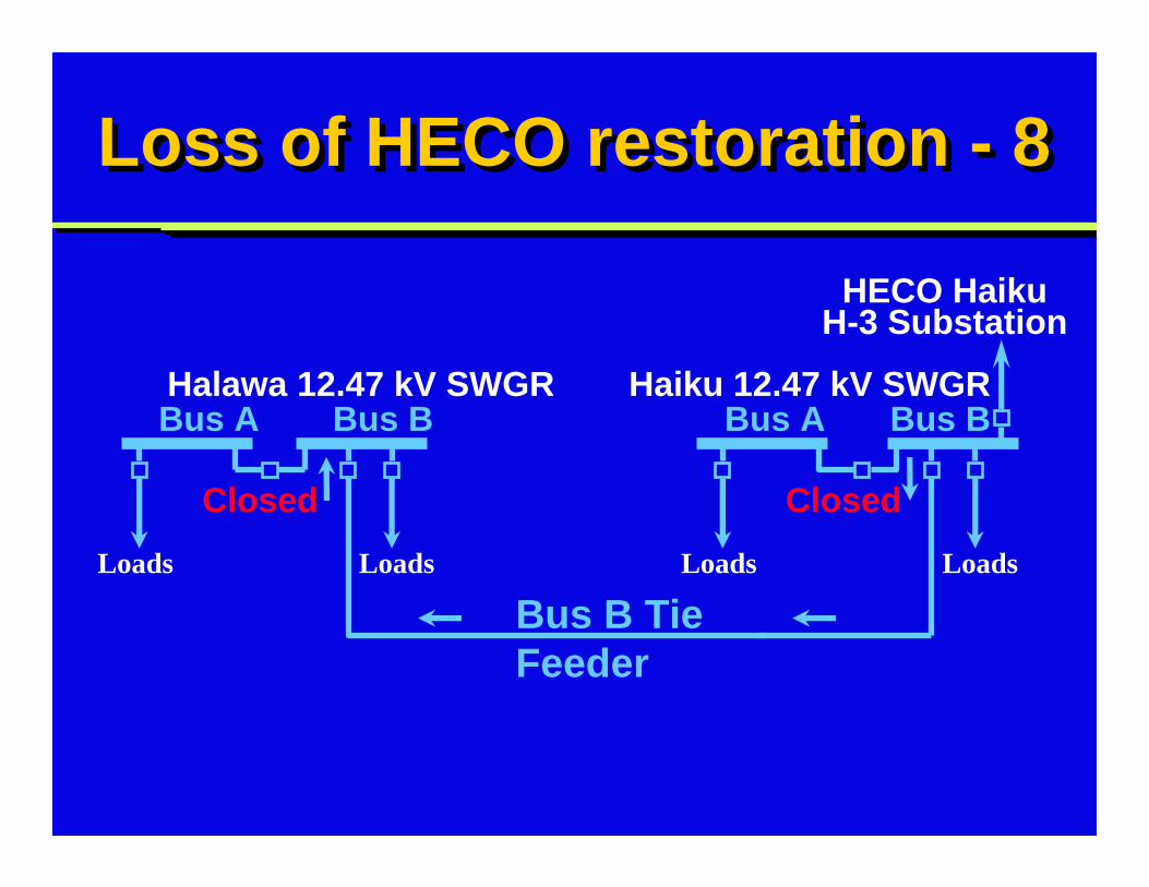
Loss of HECO restoration - 8Loss of HECO restoration - 8
Halawa 12.47 kV SWGR
HECO HaikuH-3 Substation
Haiku 12.47 kV SWGR
Local manual restorationLocal manual restoration
Personnel required at both Halawa and Haiku swgrLocal auto-manual switch (43AM)43AM in manual to override switchgear automatic featuresRandom operations will open and close other breakers
Personnel required at both Halawa and Haiku swgrLocal auto-manual switch (43AM)43AM in manual to override switchgear automatic featuresRandom operations will open and close other breakers
Remote manual restorationRemote manual restoration
Through control room computer43COMP is similar to local 43AM switch43COMP is a control relayEnergize 43COMP relay = manual
Through control room computer43COMP is similar to local 43AM switch43COMP is a control relayEnergize 43COMP relay = manual
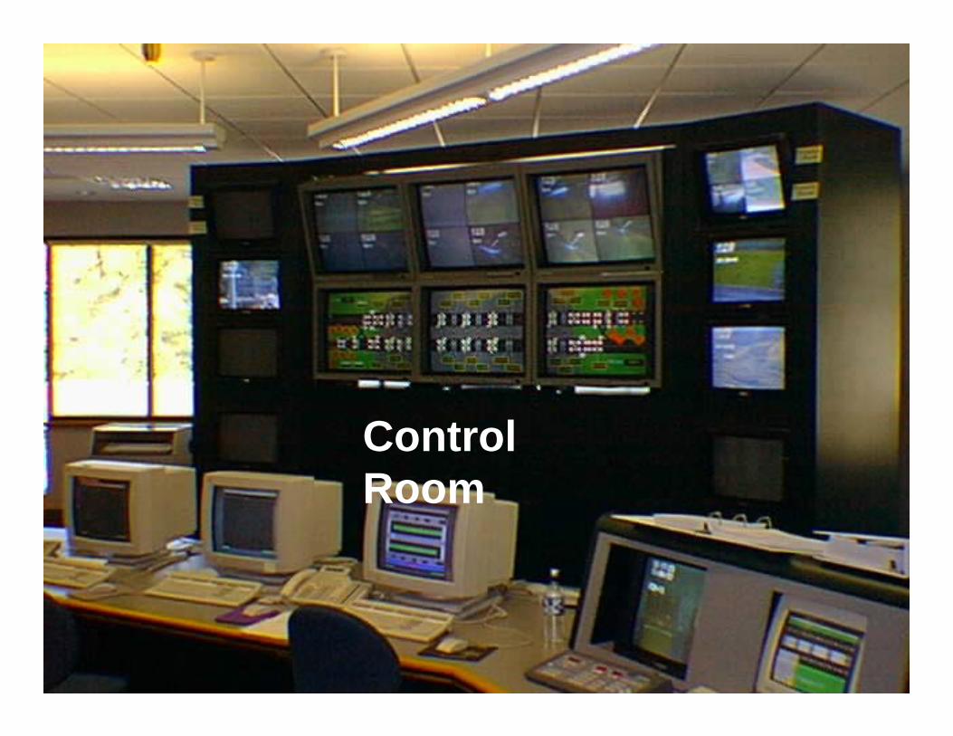
Photo: Control RoomPhoto: Control Room
Control Room
12.47 kV relay settings12.47 kV relay settings
Very inverse OC relays set for max loadingCoordination very difficult, many combinationsSpecial setting for instantaneous relaysLarge inrush current from many transformers
Very inverse OC relays set for max loadingCoordination very difficult, many combinationsSpecial setting for instantaneous relaysLarge inrush current from many transformers
480 V load centers480 V load centers
Two 2,500 kVA, 12.47 kV -480Y/277 V transformersFully-sized, all 4 portal buildingsAlso split-bus configuration w/automatic restorationRestoration via local or remote
Two 2,500 kVA, 12.47 kV -480Y/277 V transformersFully-sized, all 4 portal buildingsAlso split-bus configuration w/automatic restorationRestoration via local or remote
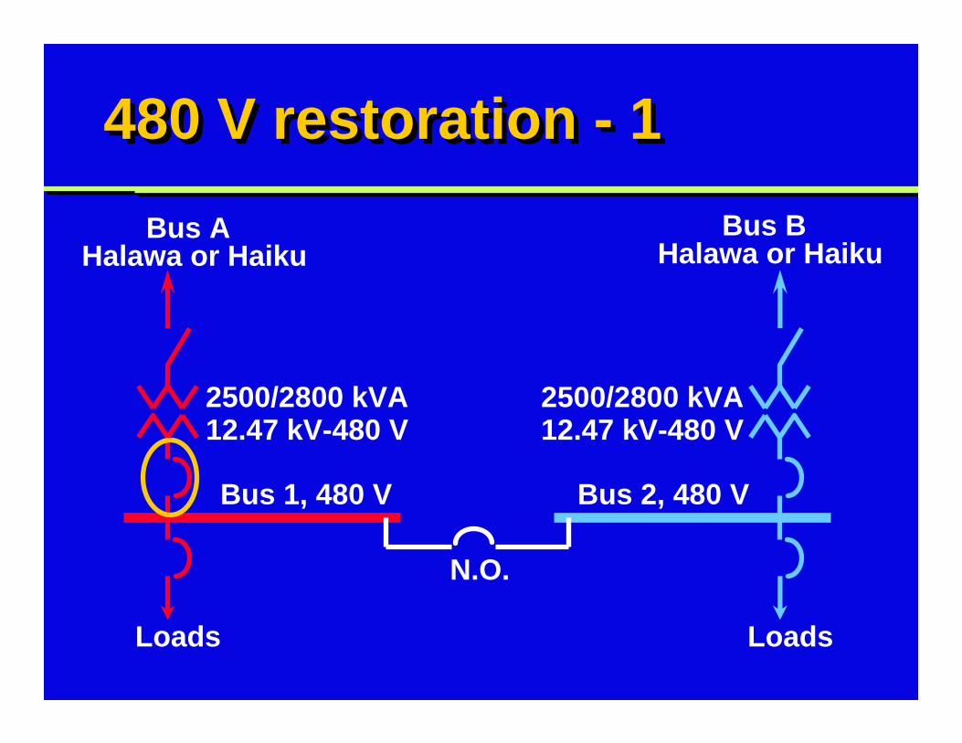
480 V restoration - 1480 V restoration - 1Bus A
Halawa or HaikuBus B
Halawa or Haiku
Loads Loads
N.O.
2500/2800 kVA12.47 kV-480 V
2500/2800 kVA12.47 kV-480 V
Bus 1, 480 V Bus 2, 480 V
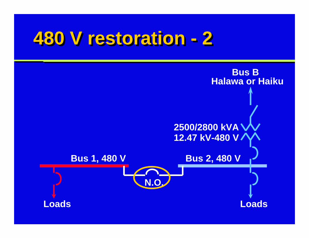
480 V restoration - 2480 V restoration - 2Bus B
Halawa or Haiku
Loads Loads
N.O.
2500/2800 kVA12.47 kV-480 V
Bus 1, 480 V Bus 2, 480 V
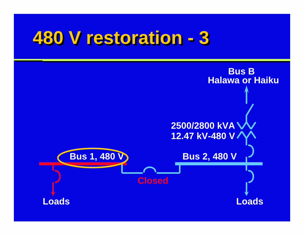
480 V restoration - 3480 V restoration - 3Bus B
Halawa or Haiku
Loads Loads
Closed
2500/2800 kVA12.47 kV-480 V
Bus 1, 480 V Bus 2, 480 V
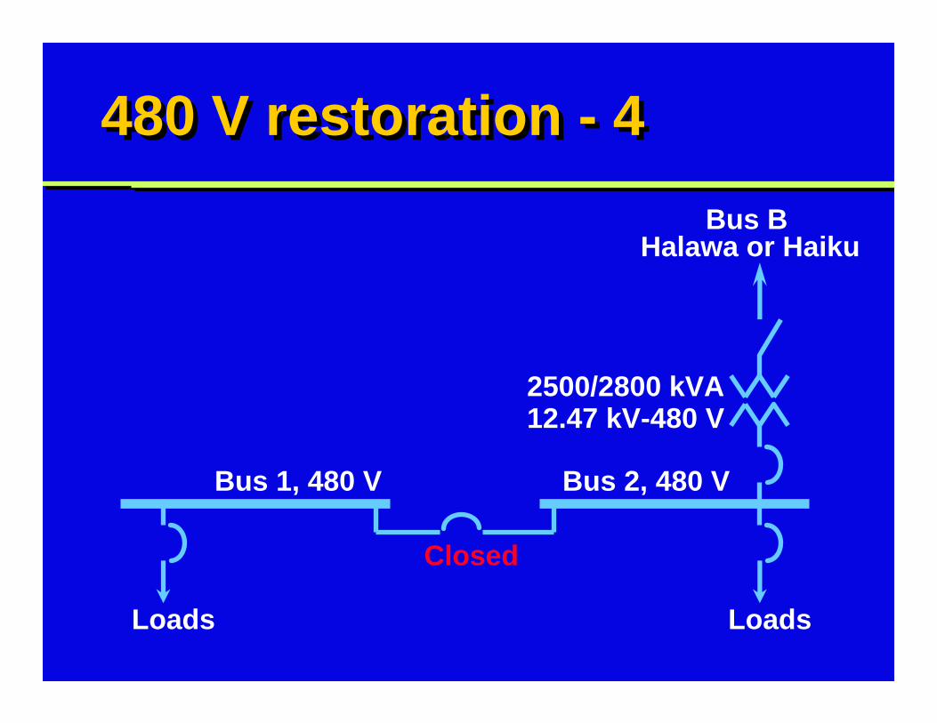
480 V restoration - 4480 V restoration - 4Bus B
Halawa or Haiku
Loads Loads
Closed
2500/2800 kVA12.47 kV-480 V
Bus 1, 480 V Bus 2, 480 V
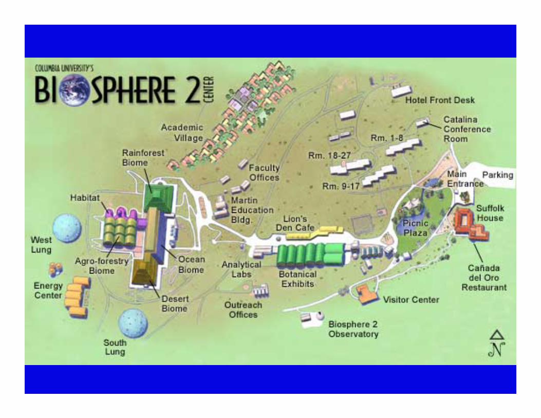
Project No. 2: Biosphere 2Project No. 2: Biosphere 2
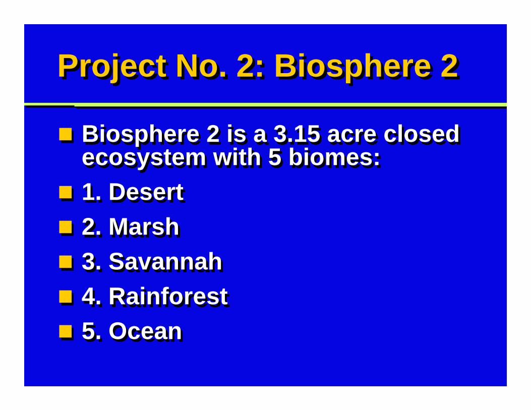
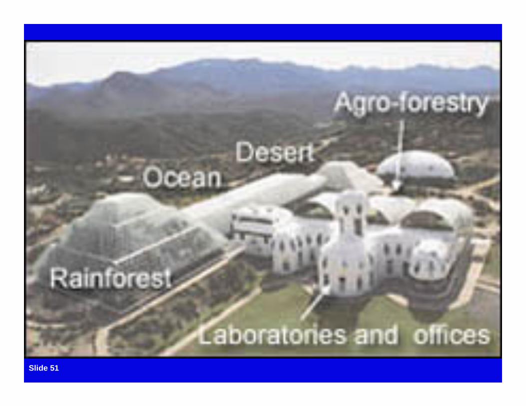
Biosphere 2 is a 3.15 acre closed ecosystem with 5 biomes:1. Desert2. Marsh3. Savannah4. Rainforest5. Ocean
Biosphere 2 is a 3.15 acre closed ecosystem with 5 biomes:1. Desert2. Marsh3. Savannah4. Rainforest5. Ocean
Project No. 2: Biosphere 2Project No. 2: Biosphere 2
Original intent: experimentation for space travelLearn from sealing 8 people in closed system1st mission: 2 years, September 1991Mission-critical: requires high reliability power system
Original intent: experimentation for space travelLearn from sealing 8 people in closed system1st mission: 2 years, September 1991Mission-critical: requires high reliability power system
Slide 51

Cogeneration power plantCogeneration power plant
Biosphere 2 cogeneration power plant produces:Electrical energyHot water for heatingCold water for coolingWaste heat from engine captured to run absorption chiller
Biosphere 2 cogeneration power plant produces:Electrical energyHot water for heatingCold water for coolingWaste heat from engine captured to run absorption chiller
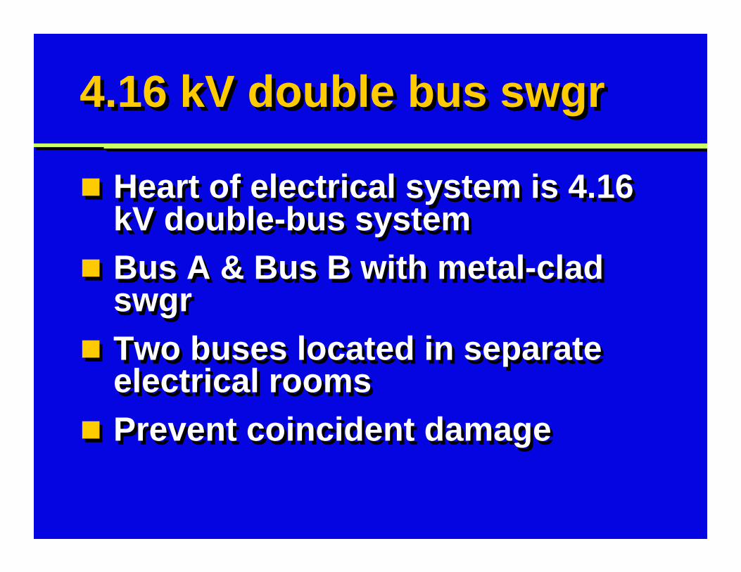
4.16 kV double bus swgr4.16 kV double bus swgr
Heart of electrical system is 4.16 kV double-bus systemBus A & Bus B with metal-clad swgrTwo buses located in separate electrical roomsPrevent coincident damage
Heart of electrical system is 4.16 kV double-bus systemBus A & Bus B with metal-clad swgrTwo buses located in separate electrical roomsPrevent coincident damage
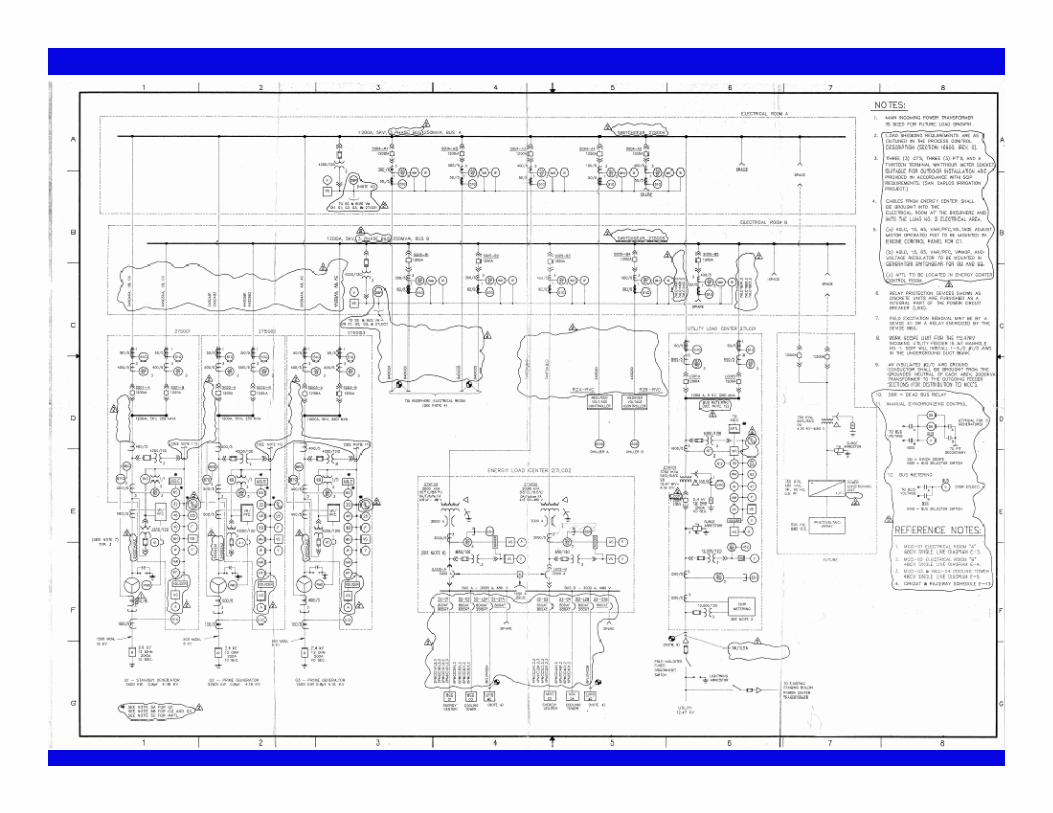
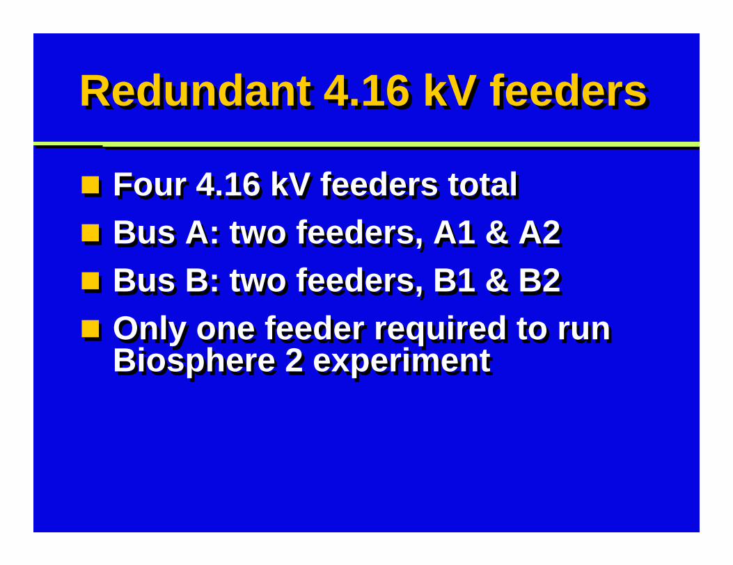
Redundant 4.16 kV feedersRedundant 4.16 kV feeders
Four 4.16 kV feeders totalBus A: two feeders, A1 & A2Bus B: two feeders, B1 & B2Only one feeder required to run Biosphere 2 experiment
Four 4.16 kV feeders totalBus A: two feeders, A1 & A2Bus B: two feeders, B1 & B2Only one feeder required to run Biosphere 2 experiment
Engine-generators, 4.16 kVEngine-generators, 4.16 kV
3 engine-generators, dual-fuelStandby & prime: 5,250 kW totalG1, standby generator, 1,500 kWG2, prime generator, 2,250 kWG3, prime generator, 1,500 kW2 generator breakers to Bus A & B
3 engine-generators, dual-fuelStandby & prime: 5,250 kW totalG1, standby generator, 1,500 kWG2, prime generator, 2,250 kWG3, prime generator, 1,500 kW2 generator breakers to Bus A & B
480 V double-ended subs480 V double-ended subs
Power plant parasitic loads from load center 27LC02Double-ended substationTwo 2,000 kVA, 4160-480 V transformers, fully-sizedSplit bus configuration: main-tie-main
Power plant parasitic loads from load center 27LC02Double-ended substationTwo 2,000 kVA, 4160-480 V transformers, fully-sizedSplit bus configuration: main-tie-main
Utility as back-upUtility as back-up
Energy center generators provide primary powerElectric utility serves as back-upOne 3,750 kVA, 12.47-4.16 kV transformerImport of 50 kW, APTL controller
Energy center generators provide primary powerElectric utility serves as back-upOne 3,750 kVA, 12.47-4.16 kV transformerImport of 50 kW, APTL controller
Future solar PV arrayFuture solar PV array
Provisions for 3rd power source:500 kW solar photovoltaic arrayDC to AC inverter750 kVA, 480-4160 V step–up transformer
Provisions for 3rd power source:500 kW solar photovoltaic arrayDC to AC inverter750 kVA, 480-4160 V step–up transformer
Project No. 3: MotorolaProject No. 3: Motorola
HV Distribution System UpgradeDesign/build for Motorola plant in Plantation, Florida30-year-old electrical systemFailures: Al feeder cables and transformer
HV Distribution System UpgradeDesign/build for Motorola plant in Plantation, Florida30-year-old electrical systemFailures: Al feeder cables and transformer

Slide 63
Project No. 3: MotorolaProject No. 3: Motorola
Prime directive: keep production lines runningDowntime costs: $300,000 per hourMotorola required highly reliable power system
Prime directive: keep production lines runningDowntime costs: $300,000 per hourMotorola required highly reliable power system
Old 13.2 kV utilityOld 13.2 kV utility
Two FP&L services at 13.2 kVShared with other customers1. Vault with transformers & 480 V feeders2. 13.2 kV fused switches & 13.2 kV feedersRadial feeders to transformers
Two FP&L services at 13.2 kVShared with other customers1. Vault with transformers & 480 V feeders2. 13.2 kV fused switches & 13.2 kV feedersRadial feeders to transformers
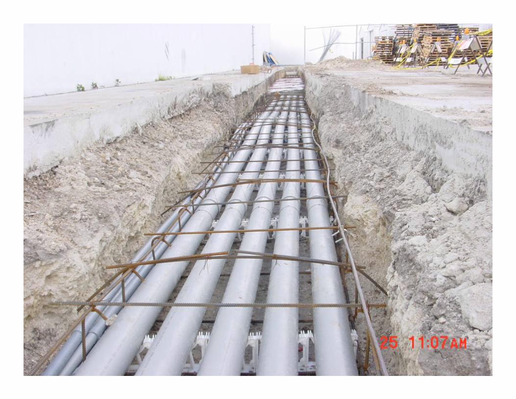
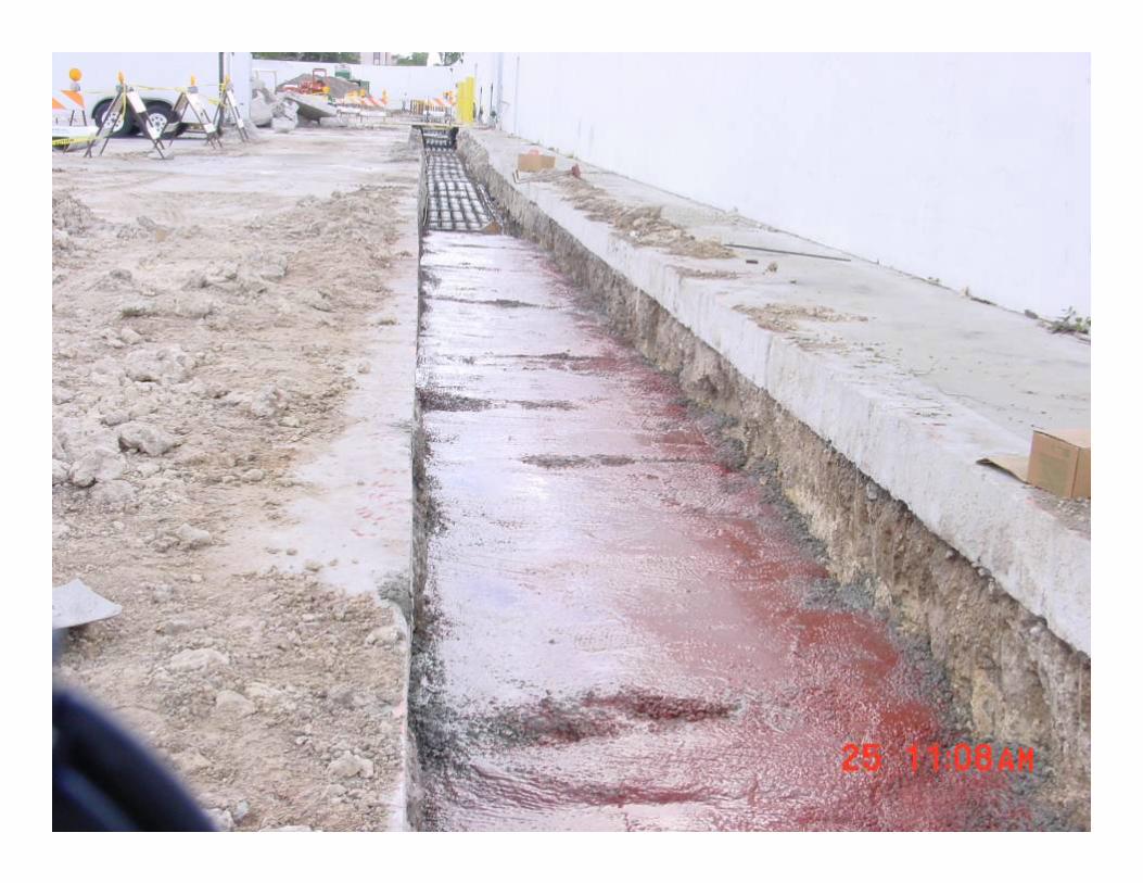
New 23 kV distributionNew 23 kV distribution
New 23 kV substation for two 23 kV FP&L feeders23 kV permits higher power transferPeak demand = 10 MWDedicated feeders from FP&L substation
New 23 kV substation for two 23 kV FP&L feeders23 kV permits higher power transferPeak demand = 10 MWDedicated feeders from FP&L substation
Slide 67
Slide 68
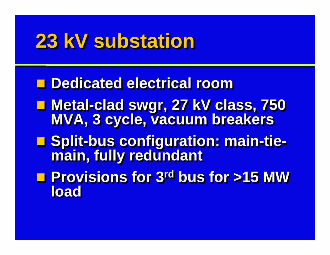
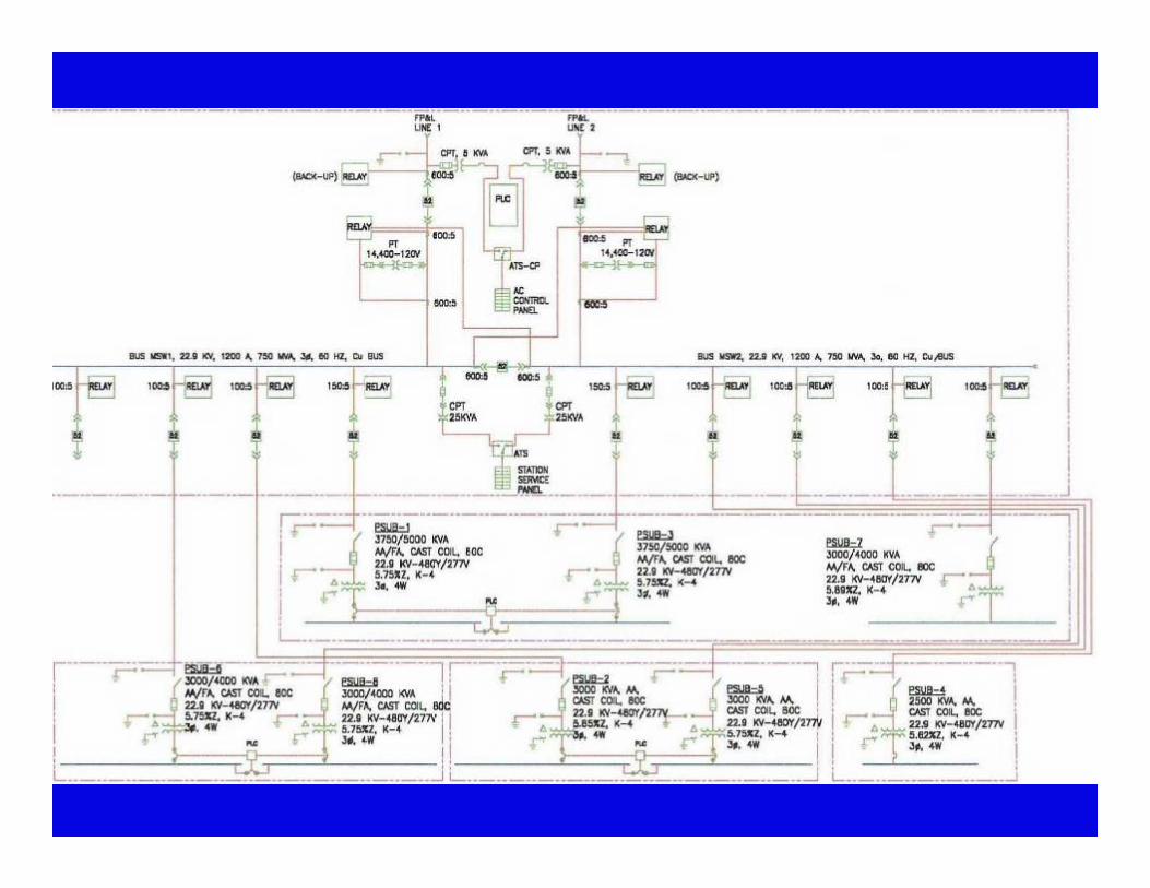
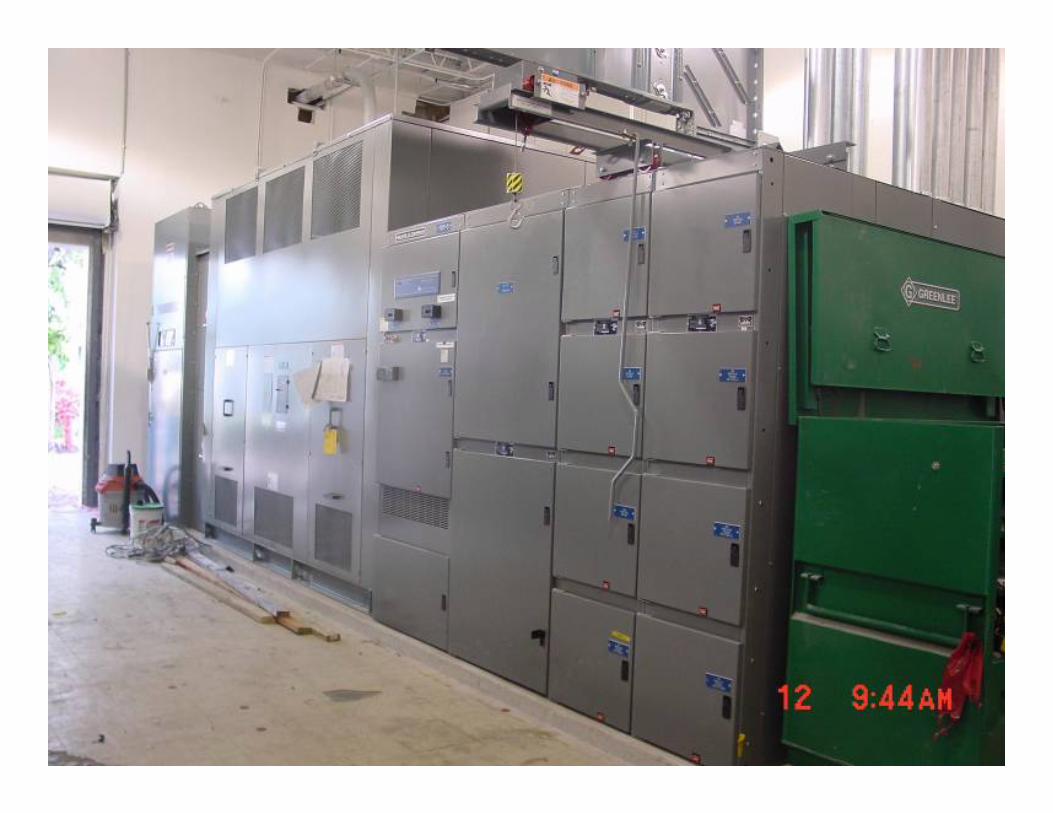
23 kV substation23 kV substation
Dedicated electrical roomMetal-clad swgr, 27 kV class, 750 MVA, 3 cycle, vacuum breakersSplit-bus configuration: main-tie-main, fully redundantProvisions for 3rd bus for >15 MW load
Dedicated electrical roomMetal-clad swgr, 27 kV class, 750 MVA, 3 cycle, vacuum breakersSplit-bus configuration: main-tie-main, fully redundantProvisions for 3rd bus for >15 MW load
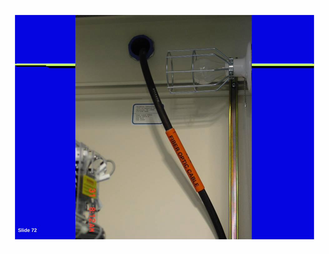
23 kV FP&L vault23 kV FP&L vault
Adjacent FP&L vault: HV switches, relays, metersFiber optic link from FP&L substationDirect communication for breaker & relay status
Adjacent FP&L vault: HV switches, relays, metersFiber optic link from FP&L substationDirect communication for breaker & relay status
Slide 72
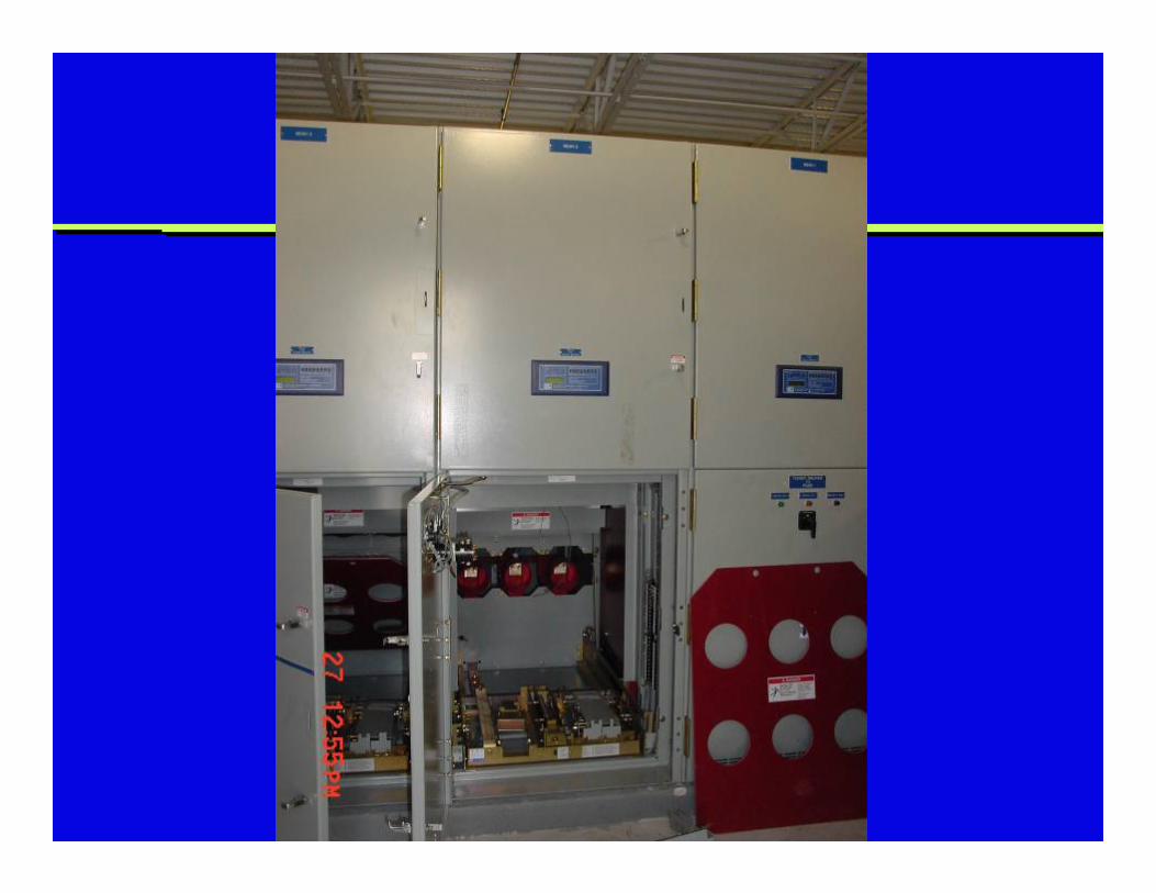
Electronic relaysElectronic relays
All relays: electronic solid-stateTwo main breakers had back-up relaysRS-232 link permitted uploading of settings
All relays: electronic solid-stateTwo main breakers had back-up relaysRS-232 link permitted uploading of settings
Switchgear control powerSwitchgear control power
Combination of AC and DC powerAC: close vacuum circuit breakersDC for critical loads:1. Trip circuit breakers2. PLC3. Relays
Combination of AC and DC powerAC: close vacuum circuit breakersDC for critical loads:1. Trip circuit breakers2. PLC3. Relays
Control power from PTsControl power from PTs
AC control power from 2 PTs at both 23 kV busesOne bus may be unavailableATS to select either bus
AC control power from 2 PTs at both 23 kV busesOne bus may be unavailableATS to select either bus
DC power from batteriesDC power from batteries
DC power from battery banks2 battery banks for increased reliabilityATS selects either battery bankPrimary: gel cell batteriesSecondary: sealed cell batteries
DC power from battery banks2 battery banks for increased reliabilityATS selects either battery bankPrimary: gel cell batteriesSecondary: sealed cell batteries
PLCPLC
PLC used to control swgrActuates local annunciator boardSends automatic alarm to electrical personnel, pager on weekends
PLC used to control swgrActuates local annunciator boardSends automatic alarm to electrical personnel, pager on weekends
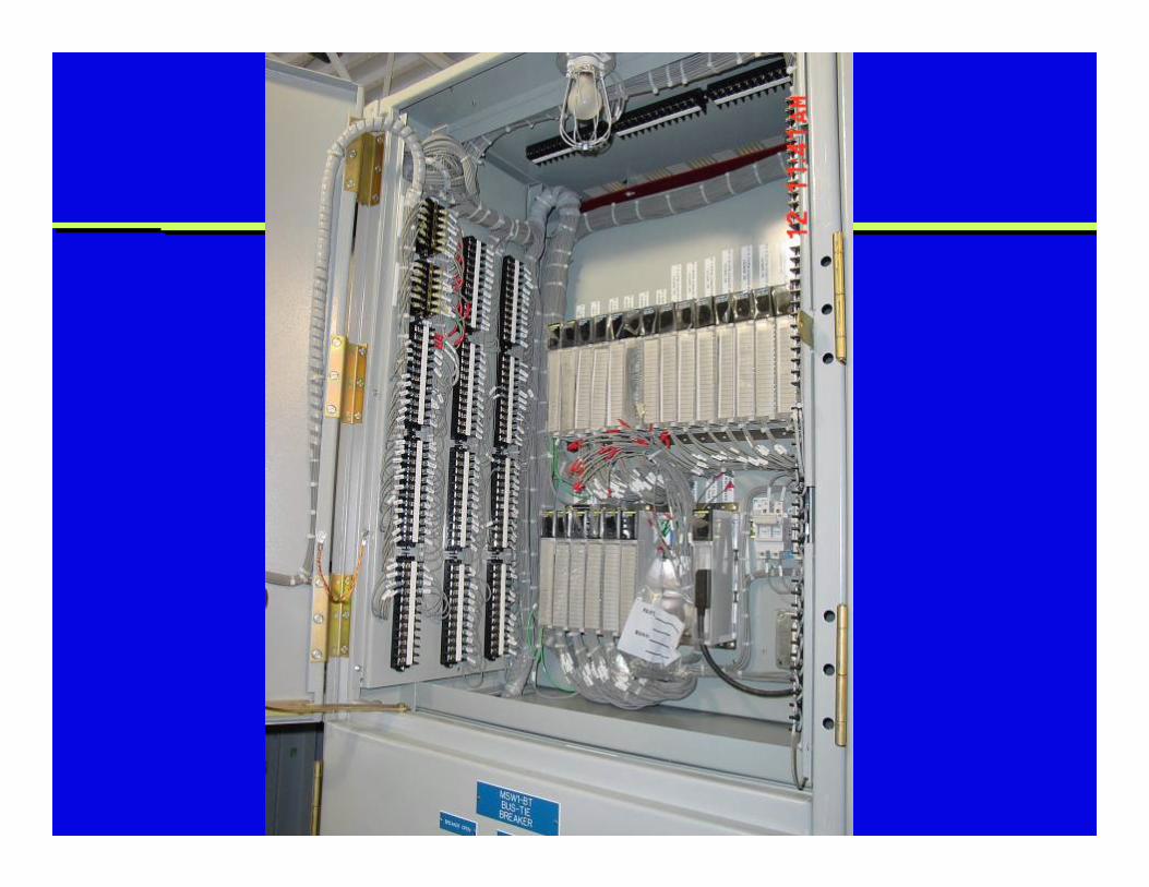
PLC alarms (partial list)PLC alarms (partial list)
PLC internal failureSwitchgear battery ground faultSwitchgear DC bus failureSwitchgear battery charger failureMain breaker relay failureClosed transition failureAir conditioner failure
PLC internal failureSwitchgear battery ground faultSwitchgear DC bus failureSwitchgear battery charger failureMain breaker relay failureClosed transition failureAir conditioner failure
PLC high output cardsPLC high output cards
Increased reliability with direct tripping of breakersUse PLC high output cardsAdvantages: less time to trip, less component failureOld method: interposing relay
Increased reliability with direct tripping of breakersUse PLC high output cardsAdvantages: less time to trip, less component failureOld method: interposing relay
Closed transition transferClosed transition transfer
Unique: closed transition transfer (i.e., make-before-break)No interruption to plantUsually not allowed by utilityRestrictions: 1 second, frequency check, synch check
Unique: closed transition transfer (i.e., make-before-break)No interruption to plantUsually not allowed by utilityRestrictions: 1 second, frequency check, synch check

Closed transition transferClosed transition transfer
Normal configuration: split-bus, open bus-tieIf: loss of one FP&L feederThen: close bus-tieThen: open mainReverse upon return
Normal configuration: split-bus, open bus-tieIf: loss of one FP&L feederThen: close bus-tieThen: open mainReverse upon return
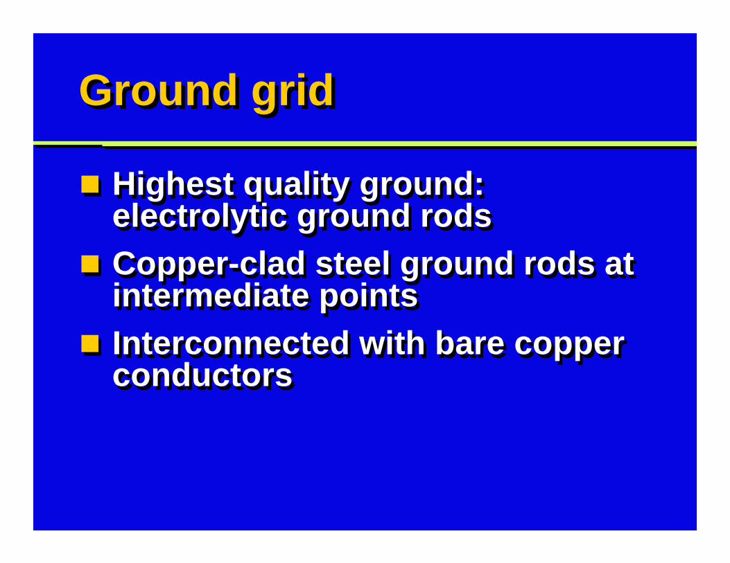
Ground gridGround grid
Highest quality ground: electrolytic ground rodsCopper-clad steel ground rods at intermediate pointsInterconnected with bare copper conductors
Highest quality ground: electrolytic ground rodsCopper-clad steel ground rods at intermediate pointsInterconnected with bare copper conductors
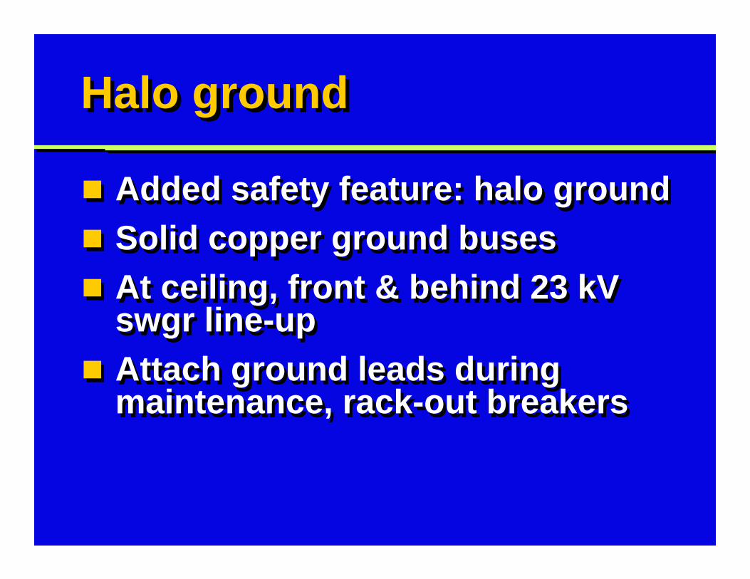
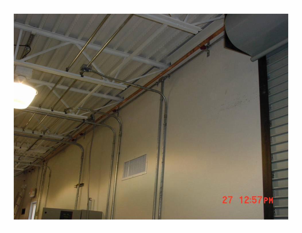
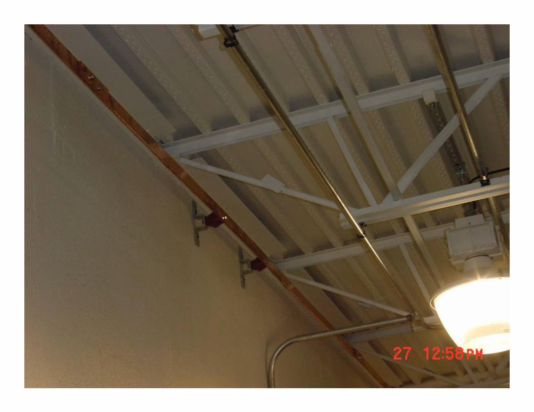
Halo groundHalo ground
Added safety feature: halo groundSolid copper ground busesAt ceiling, front & behind 23 kV swgr line-upAttach ground leads during maintenance, rack-out breakers
Added safety feature: halo groundSolid copper ground busesAt ceiling, front & behind 23 kV swgr line-upAttach ground leads during maintenance, rack-out breakers
Slide 86
Slide 87
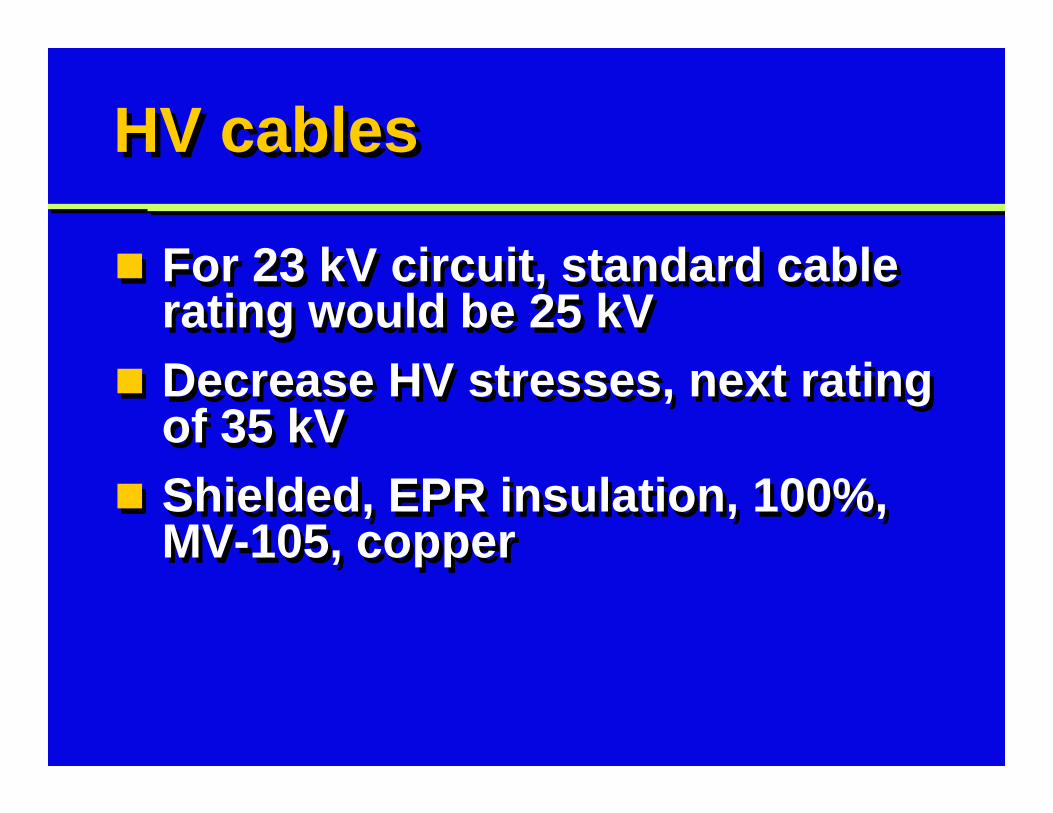
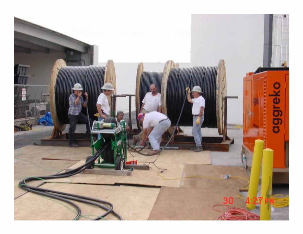
HV cablesHV cables
For 23 kV circuit, standard cable rating would be 25 kVDecrease HV stresses, next rating of 35 kVShielded, EPR insulation, 100%, MV-105, copper
For 23 kV circuit, standard cable rating would be 25 kVDecrease HV stresses, next rating of 35 kVShielded, EPR insulation, 100%, MV-105, copper
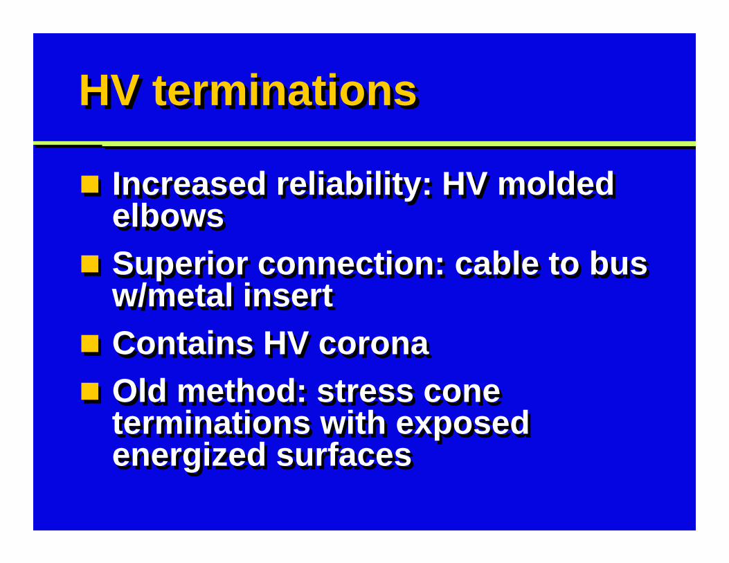
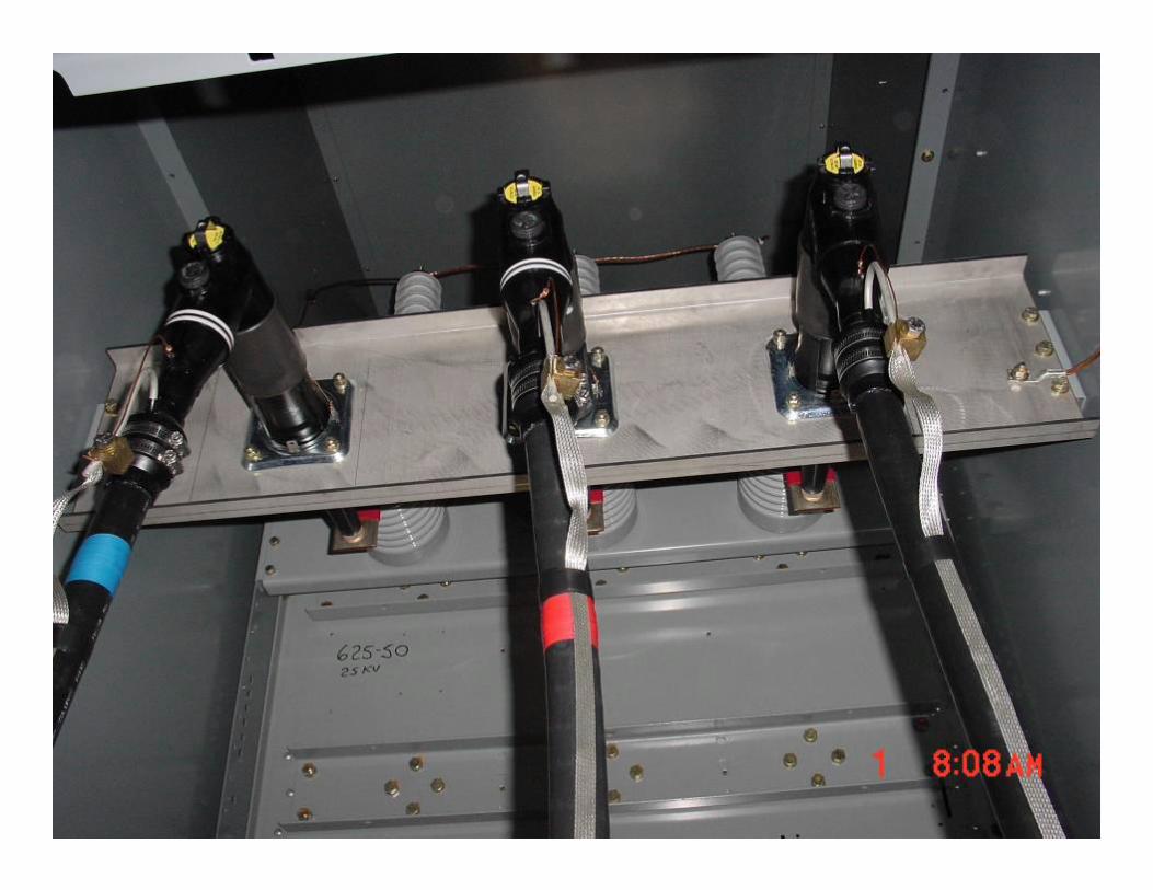
HV terminationsHV terminations
Increased reliability: HV molded elbowsSuperior connection: cable to bus w/metal insertContains HV coronaOld method: stress cone terminations with exposed energized surfaces
Increased reliability: HV molded elbowsSuperior connection: cable to bus w/metal insertContains HV coronaOld method: stress cone terminations with exposed energized surfaces
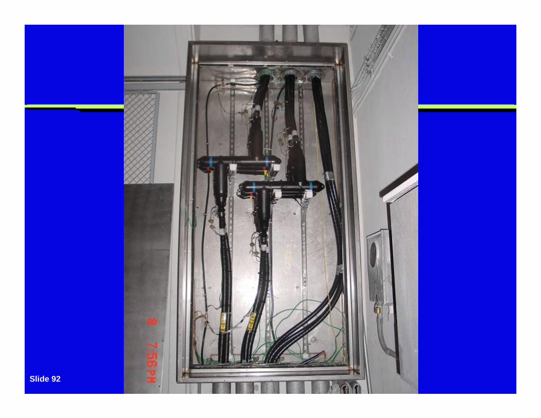
Slide 92
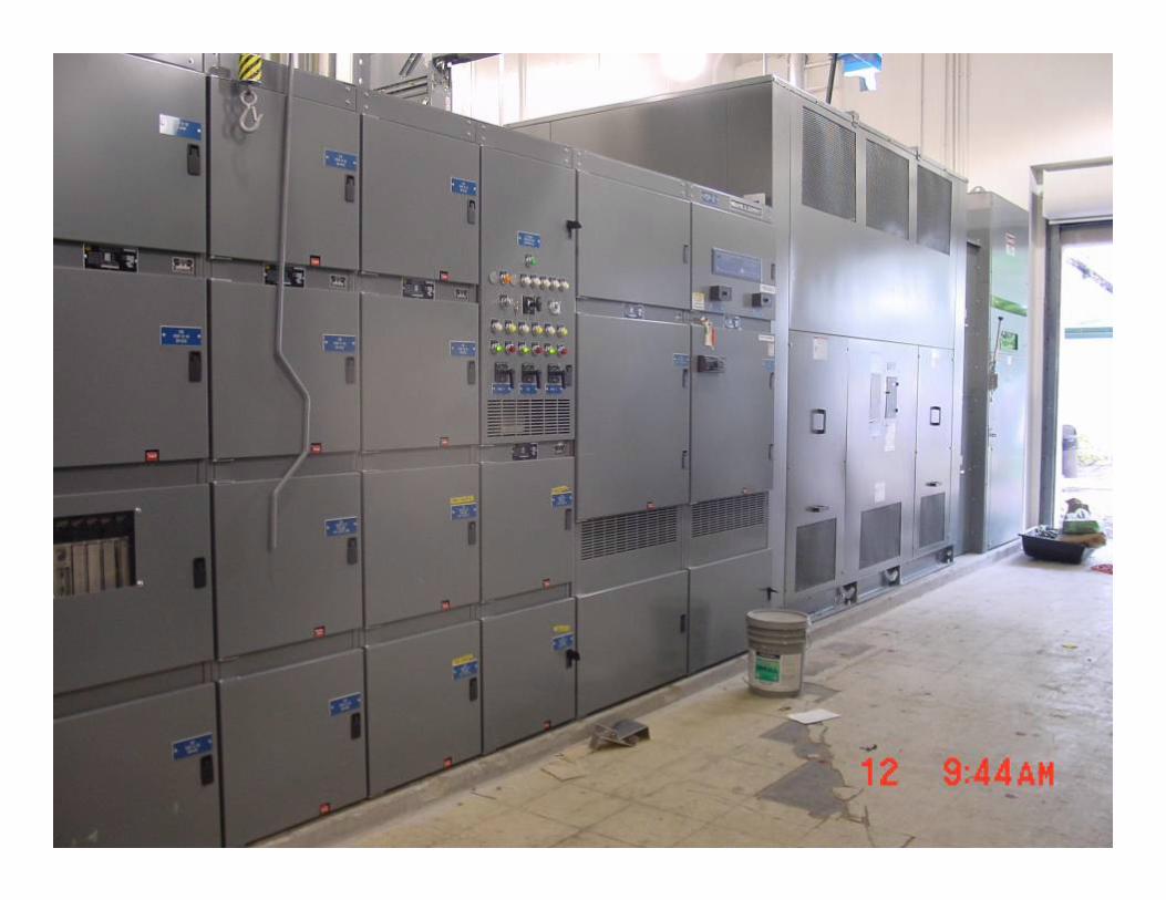
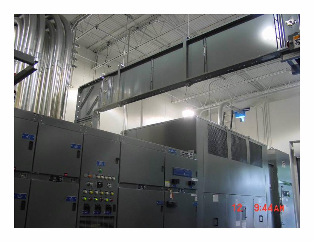
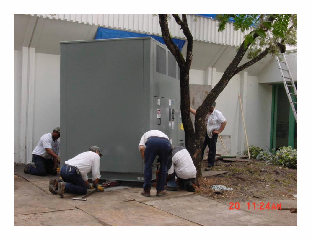
480 V double-ended subs480 V double-ended subs
Improved reliability, 480 V double-ended substationsSplit-bus: main-tie-mainFully-rated transformers, 23 kV-480 volts
Improved reliability, 480 V double-ended substationsSplit-bus: main-tie-mainFully-rated transformers, 23 kV-480 volts
Slide 95
Slide 96
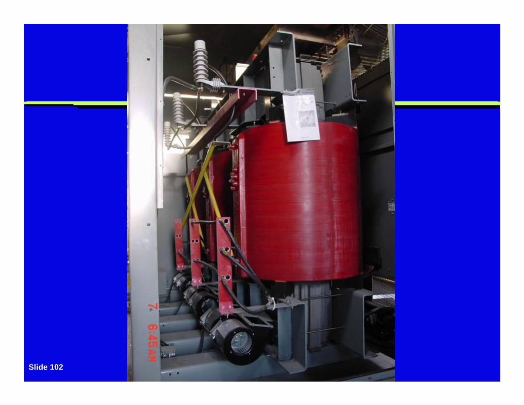
Best cast coil transformersBest cast coil transformers
No spill containmentNo liquid (fire or environmental)Better surge capability, epoxy cast over coilsLess space required, no finsFewer maintenance tests (e.g., no dissolved gas-in-oil)
No spill containmentNo liquid (fire or environmental)Better surge capability, epoxy cast over coilsLess space required, no finsFewer maintenance tests (e.g., no dissolved gas-in-oil)
Closed transition transferClosed transition transfer
480 V swgr repeats closed transition transfer functionCould parallel 23 kV lines at 480 V swgrSafeguard: control wires as permissive in 480 V swgr PLCCheck for status of 23 kV breakers
480 V swgr repeats closed transition transfer functionCould parallel 23 kV lines at 480 V swgrSafeguard: control wires as permissive in 480 V swgr PLCCheck for status of 23 kV breakers
Transformer HV switchTransformer HV switch
Transformer directly coupled to 23 kV fused air switchFuse provides internal transformer fault protectionLocal disconnecting means for maintenance
Transformer directly coupled to 23 kV fused air switchFuse provides internal transformer fault protectionLocal disconnecting means for maintenance
Lightning arrestersLightning arresters
HV lightning arresters: transformer primaryMetal-oxide, 15.8 kVProtects from damaging HV spikes & surgesAdded reliability: 2nd set of arresters, line side of switch
HV lightning arresters: transformer primaryMetal-oxide, 15.8 kVProtects from damaging HV spikes & surgesAdded reliability: 2nd set of arresters, line side of switch
Slide 102
Summary: H-3 TunnelSummary: H-3 Tunnel
4 sources of power for critical loadsFeatures: redundancy and flexibilitySignificant: 12.47 kV swgr interlockingImmediate auto restoration of powerHigh reliability power system
4 sources of power for critical loadsFeatures: redundancy and flexibilitySignificant: 12.47 kV swgr interlockingImmediate auto restoration of powerHigh reliability power system
Summary: Biosphere 2Summary: Biosphere 2
4.16 kV dual-busSeparate electrical roomsRedundancy in 4 feeders3 engine-generatorsUtility as back-upHigh reliability power system
4.16 kV dual-busSeparate electrical roomsRedundancy in 4 feeders3 engine-generatorsUtility as back-upHigh reliability power system
Summary: MotorolaSummary: Motorola
Increase distribution voltage from 13.2 to 23 kVSplit-bus 23 kV & 480 V swgrDouble-ended substationsPLC for closed transition transfer
Increase distribution voltage from 13.2 to 23 kVSplit-bus 23 kV & 480 V swgrDouble-ended substationsPLC for closed transition transfer
Summary: MotorolaSummary: Motorola
Cast-coil transformers35 kV cables for 23 kV circuitsMolded elbows for HV terminationsDual lightning arrestersHigh reliability power system
Cast-coil transformers35 kV cables for 23 kV circuitsMolded elbows for HV terminationsDual lightning arrestersHigh reliability power system

Questions?Questions?