Embed Size (px)
Citation preview
ARTICLE
Received 10 Nov 2015 | Accepted 12 May 2016 | Published 16 Jun 2016
Three-dimensional spatiotemporal focusing ofholographic patternsOscar Hernandez1,w, Eirini Papagiakoumou1,2, Dimitrii Tanese1, Kevin Fidelin3, Claire Wyart3 & Valentina Emiliani1
Two-photon excitation with temporally focused pulses can be combined with phase-
modulation approaches, such as computer-generated holography and generalized phase
contrast, to efficiently distribute light into two-dimensional, axially confined, user-defined
shapes. Adding lens-phase modulations to 2D-phase holograms enables remote axial pattern
displacement as well as simultaneous pattern generation in multiple distinct planes. However,
the axial confinement linearly degrades with lateral shape area in previous reports where
axially shifted holographic shapes were not temporally focused. Here we report an optical
system using two spatial light modulators to independently control transverse- and
axial-target light distribution. This approach enables simultaneous axial translation of single
or multiple spatiotemporally focused patterns across the sample volume while achieving the
axial confinement of temporal focusing. We use the system’s capability to photoconvert tens
of Kaede-expressing neurons with single-cell resolution in live zebrafish larvae.
DOI: 10.1038/ncomms11928 OPEN
1 Wavefront-Engineering Microscopy Group, Neurophotonics Laboratory, CNRS UMR 8250, Paris Descartes University, UFR Biomedicale, 45 rue des Saints-Peres, 75270 Paris Cedex 06, France. 2 Institut national de la sante et de la recherche medicale (Inserm), France. 3 Institut du Cerveau et de la Moelle Epiniere,UPMC, Inserm UMR S975, CNRS UMR 7225, Campus Hospitalier Pitie Salpetriere, 47 building de l’Hopital, 75013 Paris, France. w Present address: CNCProgram, Stanford University, Stanford, California 94305, USA. Correspondence and requests for materials should be addressed to V.E. (email:[email protected]).
NATURE COMMUNICATIONS | 7:11928 | DOI: 10.1038/ncomms11928 | www.nature.com/naturecommunications 1
Since its first demonstration1, nonlinear two-photon (2P)microscopy has revolutionized diverse research fieldsincluding neuronal structural and functional imaging,
photostimulation, laser processing and lithography. Originalconfigurations were based on scanning a tightly focused pulsedlaser beam across a defined sample region with galvanometricmirrors, acousto-optic deflectors2–4 or resonant scanners5.Recently, applications including lithography, uncaging,optogenetics and fast functional imaging have motivatedscanless 2P-excitation method development, enablingsimultaneous illumination of laterally extended regions ofinterest while preserving micrometre axial confinement. Thiswas achieved by axially confining large spots generated bylow-numerical aperture (NA) Gaussian beams with temporalfocusing (TF)6,7. In TF, a diffraction grating conjugated to thesample plane diffracts the different spectral frequenciescomprising an ultrashort excitation pulse towards differentdirections. The various frequencies thus propagate towards theobjective focal plane at different angles, such that spatiotemporalcoupling effects8 lead to temporal pulse broadening above andbelow the focal plane, which remains the only region irradiated atpeak powers efficient for 2P excitation. In this way, TF enablesaxial confinement equivalent to that of line-scanning microscopythat is independent of the excitation beam’s lateral extent.Investigators have applied TF to imaging9–13, functionalimaging14,15, super-resolution imaging16, lithography17 andneuronal photostimulation18,19 by generating circular-spotshapes only.
As a more flexible way to elaborate light patterning, phase-modulation approaches using liquid-crystal spatial light mod-ulators, such as computer-generated holography (CGH)20,21 andgeneralized phase contrast (GPC)22 have demonstrated efficientlight sculpting in two-dimensional (2D) user-defined shapes.Combined with TF to axially confine the shapes, CGH and GPCcan sculpt 2P-excitation volumes with the micrometre precisionneeded to illuminate small structures, such as neuronaldendrites22,23. These methods also enable 2P optogeneticstimulation with high temporal resolution and robustness toscattering23,24.
CGH can also sculpt light in three dimensions (3D)25, a featureused to generate multidiffraction-limited traps for opticaltweezers26,27 and 3D glutamate uncaging28,29. Although not yetdemonstrated with 2P excitation, adding lens-phase modulationsto 2D-phase holograms also enables remote axial displacementand 3D positioning of laterally shaped targets27,30,31.
Combining CGH’s 3D light-shaping capability with 2Pexcitation can significantly broaden the range of possibleapplications. For example, simultaneous multiplane holographicpattern generation can enable fast 2P multiplane imaging,photostimulation and photo-polymerization methods. Inaddition, remote axial displacement of holographic targets cancouple holographic illumination with a second imaging orstimulation channel, providing independent control of theirrespective focal planes32, as well as remote volume scanning.However, previous 3D CGH optical configurations could not beimplemented with TF because axially shifted excitation planescannot be simultaneously imaged on the TF grating. Thisshortcoming restricted CGH-TF to 2D patterns focused at theobjective focal plane21.
Here we demonstrate a unique optical system overcoming thislimitation. The system achieves remote axial displacement oftemporally focused holographic beams as well as multipletemporally focused planes by shaping the incoming wavefrontin two steps using two spatial light modulators (SLMs). A firstSLM laterally shapes the target light distribution that is focusedon the TF grating, while a second SLM, positioned after the
grating, controls the axial position(s) of the spatiotemporal focalplane(s) in the sample volume. By integrating phase profilesthat minimize optical aberrations and intensity compensationprotocols, we generate spatiotemporally focused patterns withuniform light distribution throughout the entire accessiblevolume, and demonstrate generation of laterally shapedtargets across an unprecedented axial range. We apply axiallyconfined multiplane light illumination to photoconvert in vivoKaede-protein-expressing neurons in zebrafish larvae. The systemenables cellular resolution photoconversion of tens of spinal cordneurons occupying separate axial planes.
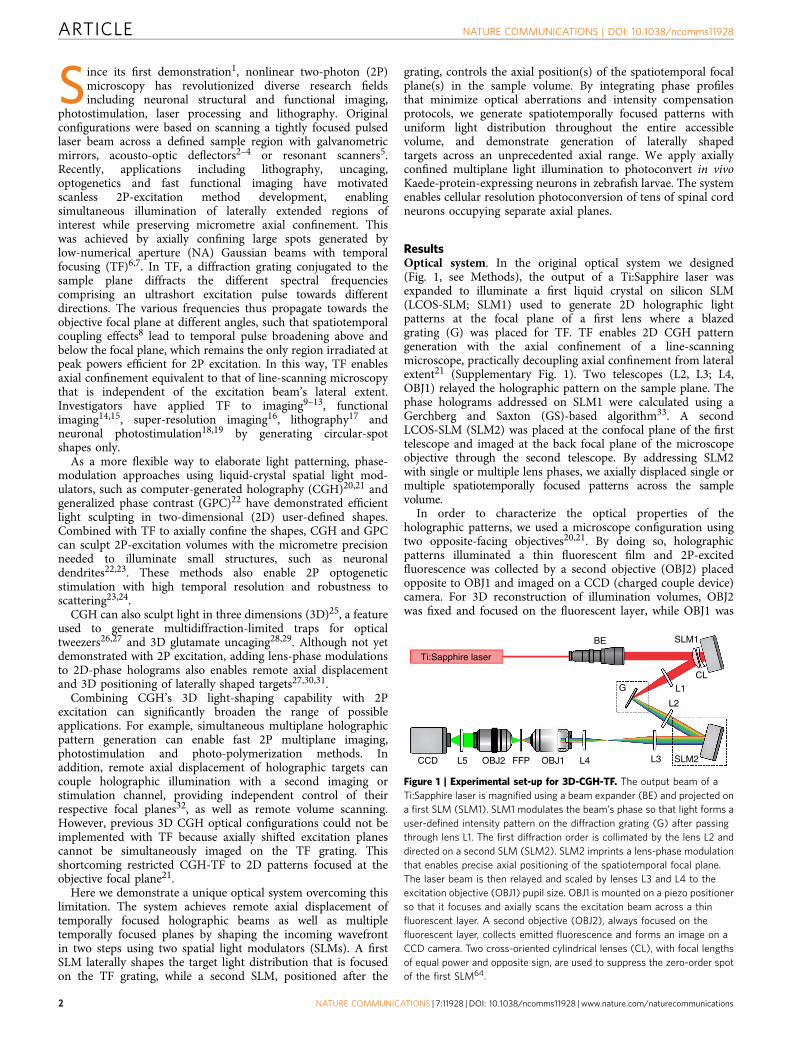
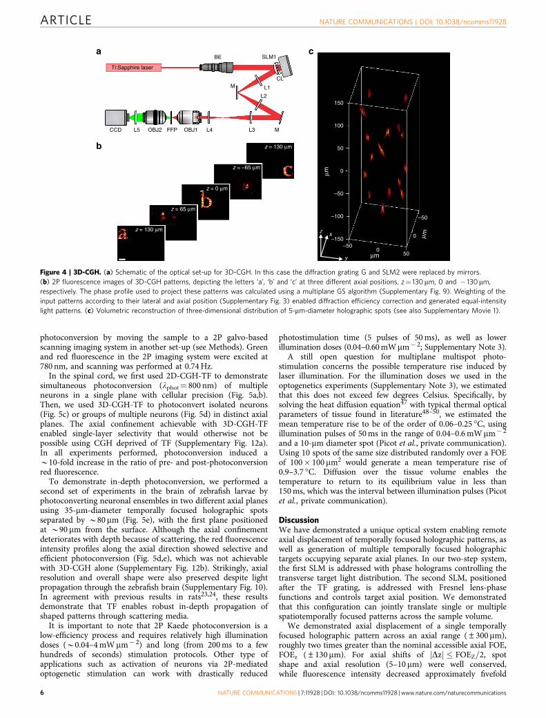
ResultsOptical system. In the original optical system we designed(Fig. 1, see Methods), the output of a Ti:Sapphire laser wasexpanded to illuminate a first liquid crystal on silicon SLM(LCOS-SLM; SLM1) used to generate 2D holographic lightpatterns at the focal plane of a first lens where a blazedgrating (G) was placed for TF. TF enables 2D CGH patterngeneration with the axial confinement of a line-scanningmicroscope, practically decoupling axial confinement from lateralextent21 (Supplementary Fig. 1). Two telescopes (L2, L3; L4,OBJ1) relayed the holographic pattern on the sample plane. Thephase holograms addressed on SLM1 were calculated using aGerchberg and Saxton (GS)-based algorithm33. A secondLCOS-SLM (SLM2) was placed at the confocal plane of the firsttelescope and imaged at the back focal plane of the microscopeobjective through the second telescope. By addressing SLM2with single or multiple lens phases, we axially displaced single ormultiple spatiotemporally focused patterns across the samplevolume.
In order to characterize the optical properties of theholographic patterns, we used a microscope configuration usingtwo opposite-facing objectives20,21. By doing so, holographicpatterns illuminated a thin fluorescent film and 2P-excitedfluorescence was collected by a second objective (OBJ2) placedopposite to OBJ1 and imaged on a CCD (charged couple device)camera. For 3D reconstruction of illumination volumes, OBJ2was fixed and focused on the fluorescent layer, while OBJ1 was
BE
Ti:Sapphire laser
CCD L5 OBJ2 FFP OBJ1 L4 L3 SLM2
SLM1
CL
L1
L2
G
Figure 1 | Experimental set-up for 3D-CGH-TF. The output beam of a
Ti:Sapphire laser is magnified using a beam expander (BE) and projected on
a first SLM (SLM1). SLM1 modulates the beam’s phase so that light forms a
user-defined intensity pattern on the diffraction grating (G) after passing
through lens L1. The first diffraction order is collimated by the lens L2 and
directed on a second SLM (SLM2). SLM2 imprints a lens-phase modulation
that enables precise axial positioning of the spatiotemporal focal plane.
The laser beam is then relayed and scaled by lenses L3 and L4 to the
excitation objective (OBJ1) pupil size. OBJ1 is mounted on a piezo positioner
so that it focuses and axially scans the excitation beam across a thin
fluorescent layer. A second objective (OBJ2), always focused on the
fluorescent layer, collects emitted fluorescence and forms an image on a
CCD camera. Two cross-oriented cylindrical lenses (CL), with focal lengths
of equal power and opposite sign, are used to suppress the zero-order spot
of the first SLM64.
ARTICLE NATURE COMMUNICATIONS | DOI: 10.1038/ncomms11928
2 NATURE COMMUNICATIONS | 7:11928 | DOI: 10.1038/ncomms11928 | www.nature.com/naturecommunications
moved along the axial direction with a piezo-scanning stage20,21.For experiments on characterizing SLM’s diffraction efficiency,the holographic patterns were directly imaged on the CCDcamera (image of the transmitted laser light). For the experimentsof photoconversion and optogenetic stimulation in zebrafishlarvae, the system was coupled to a HiLo imaging set-up(see following sections).
The optical system enabled remote axial displacement oftemporally focused holographic patterns as well as generation ofmultiple spatiotemporally focused holographic targets in distinctaxial planes. In a simplified configuration where mirrors replacedthe SLM2 and the grating, the system also generated 2Pmultiplane arbitrarily shaped non-temporally focused patterns.
Remote axial shift of spatiotemporally focused patterns. First,we demonstrated remote axial displacement of a temporallyfocused holographic pattern by separating input-beam-phasemodulation in two steps, controlling first the target lateral lightdistribution, and, second, its axial position. In contrast toconventional CGH, axial displacement of temporally focusedholographic patterns cannot be achieved by simply adding aFresnel lens to the phase hologram34 because the lens effect,by axially displacing the excitation plane with respect to the TFgrating, would forbid the spatial and temporal focal planesto coincide35. We resolved this issue by implementing a novel,two-SLM strategy. SLM1 generated 2D CGH illuminationpatterns focused on the grating G, which dispersed the spectralcomponents of the illumination pattern on SLM2. SLM2,conjugated to the objective back focal plane, was addressedwith a Fresnel lens-phase profile to control the target’s axialposition in the sample volume. This design enables the spatial andtemporal focal planes to coincide at the grating, and to be jointlytranslated by SLM2 across the sample volume axial extent.
The effect of spherical aberrations on targets generated outof OBJ1’s nominal focal plane (Supplementary Fig. 2) wasminimized by describing the objective focal sphere36 within theapproximation of small defocus and high NA. We thus addressedSLM2 with lens-phase profiles featuring spherical phase28,37:
f rð Þ ¼ kDzffiffiffiffiffiffiffiffiffiffiffiffiffiffiffiffiffiffiffiffiffiffiffin2�NA2r2
qð1Þ
where k is the free-space wavenumber, n is the refractive index ofthe immersion medium, NA is the numerical aperture of theobjective, r ¼ r
NA�feq(with feq being the equivalent focal length:
feq ¼ f3
f4fobj and r ¼
ffiffiffiffiffiffiffiffiffiffiffiffiffiffiffiffiffiffiffiffiffiffiffix2þ y2þ z2
p) is the normalized pupil at the
SLM2 plane and Dz the axial displacement of the holographiclight pattern in the sample volume.
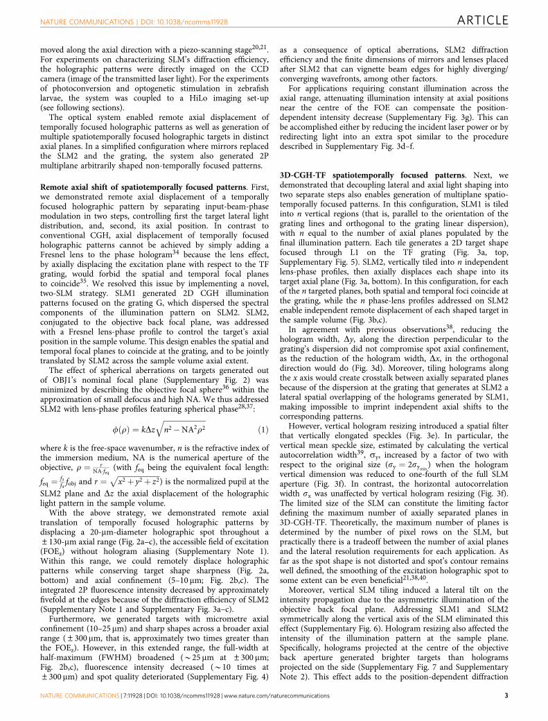
With the above strategy, we demonstrated remote axialtranslation of temporally focused holographic patterns bydisplacing a 20-mm-diameter holographic spot throughout a±130-mm axial range (Fig. 2a–c), the accessible field of excitation(FOEz) without hologram aliasing (Supplementary Note 1).Within this range, we could remotely displace holographicpatterns while conserving target shape sharpness (Fig. 2a,bottom) and axial confinement (5–10 mm; Fig. 2b,c). Theintegrated 2P fluorescence intensity decreased by approximatelyfivefold at the edges because of the diffraction efficiency of SLM2(Supplementary Note 1 and Supplementary Fig. 3a–c).
Furthermore, we generated targets with micrometre axialconfinement (10–25 mm) and sharp shapes across a broader axialrange (±300 mm, that is, approximately two times greater thanthe FOEz). However, in this extended range, the full-width athalf-maximum (FWHM) broadened (B25 mm at ±300 mm;Fig. 2b,c), fluorescence intensity decreased (B10 times at±300mm) and spot quality deteriorated (Supplementary Fig. 4)
as a consequence of optical aberrations, SLM2 diffractionefficiency and the finite dimensions of mirrors and lenses placedafter SLM2 that can vignette beam edges for highly diverging/converging wavefronts, among other factors.
For applications requiring constant illumination across theaxial range, attenuating illumination intensity at axial positionsnear the centre of the FOE can compensate the position-dependent intensity decrease (Supplementary Fig. 3g). This canbe accomplished either by reducing the incident laser power or byredirecting light into an extra spot similar to the proceduredescribed in Supplementary Fig. 3d–f.
3D-CGH-TF spatiotemporally focused patterns. Next, wedemonstrated that decoupling lateral and axial light shaping intotwo separate steps also enables generation of multiplane spatio-temporally focused patterns. In this configuration, SLM1 is tiledinto n vertical regions (that is, parallel to the orientation of thegrating lines and orthogonal to the grating linear dispersion),with n equal to the number of axial planes populated by thefinal illumination pattern. Each tile generates a 2D target shapefocused through L1 on the TF grating (Fig. 3a, top,Supplementary Fig. 5). SLM2, vertically tiled into n independentlens-phase profiles, then axially displaces each shape into itstarget axial plane (Fig. 3a, bottom). In this configuration, for eachof the n targeted planes, both spatial and temporal foci coincide atthe grating, while the n phase-lens profiles addressed on SLM2enable independent remote displacement of each shaped target inthe sample volume (Fig. 3b,c).
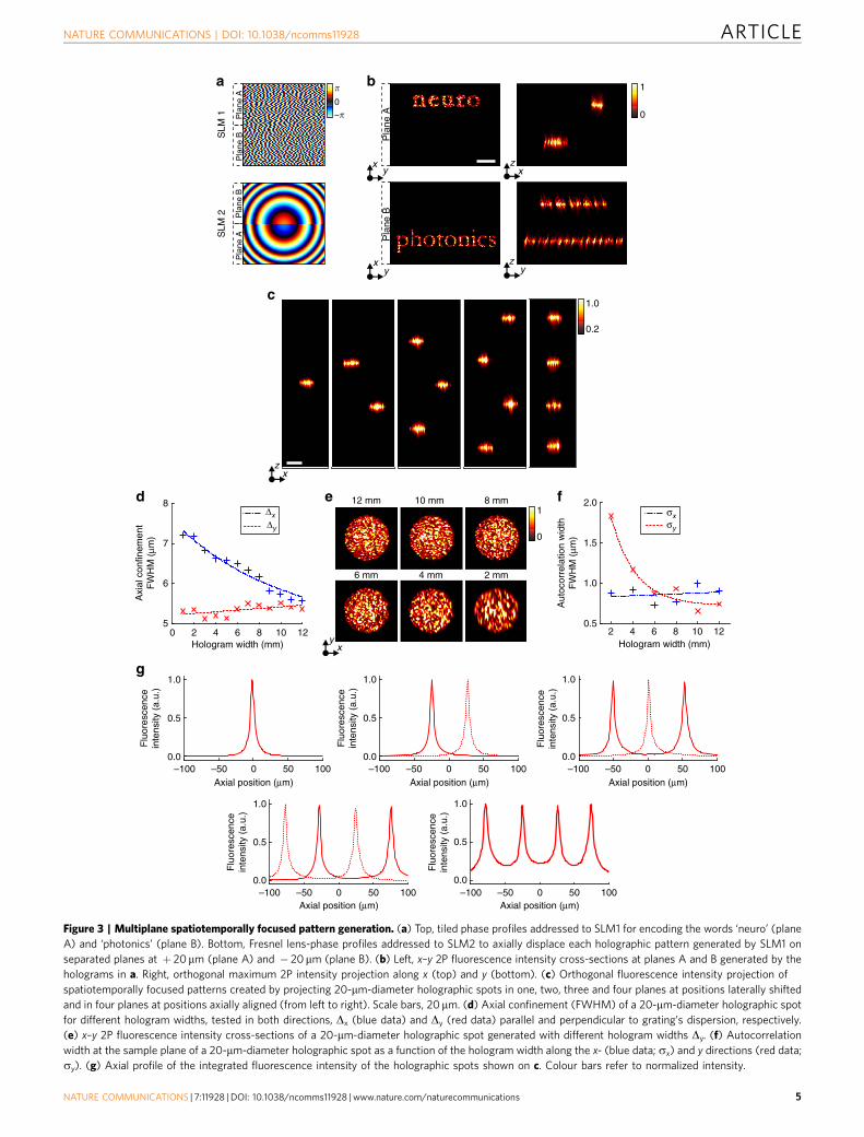
In agreement with previous observations38, reducing thehologram width, Dy, along the direction perpendicular to thegrating’s dispersion did not compromise spot axial confinement,as the reduction of the hologram width, Dx, in the orthogonaldirection would do (Fig. 3d). Moreover, tiling holograms alongthe x axis would create crosstalk between axially separated planesbecause of the dispersion at the grating that generates at SLM2 alateral spatial overlapping of the holograms generated by SLM1,making impossible to imprint independent axial shifts to thecorresponding patterns.
However, vertical hologram resizing introduced a spatial filterthat vertically elongated speckles (Fig. 3e). In particular, thevertical mean speckle size, estimated by calculating the verticalautocorrelation width39, sy, increased by a factor of two withrespect to the original size (sy ¼ 2symin
) when the hologramvertical dimension was reduced to one-fourth of the full SLMaperture (Fig. 3f). In contrast, the horizontal autocorrelationwidth sx was unaffected by vertical hologram resizing (Fig. 3f).The limited size of the SLM can constitute the limiting factordefining the maximum number of axially separated planes in3D-CGH-TF. Theoretically, the maximum number of planes isdetermined by the number of pixel rows on the SLM, butpractically there is a tradeoff between the number of axial planesand the lateral resolution requirements for each application. Asfar as the spot shape is not distorted and spot’s contour remainswell defined, the smoothing of the excitation holographic spot tosome extent can be even beneficial21,38,40.
Moreover, vertical SLM tiling induced a lateral tilt on theintensity propagation due to the asymmetric illumination of theobjective back focal plane. Addressing SLM1 and SLM2symmetrically along the vertical axis of the SLM eliminated thiseffect (Supplementary Fig. 6). Hologram resizing also affected theintensity of the illumination pattern at the sample plane.Specifically, holograms projected at the centre of the objectiveback aperture generated brighter targets than hologramsprojected on the side (Supplementary Fig. 7 and SupplementaryNote 2). This effect adds to the position-dependent diffraction
NATURE COMMUNICATIONS | DOI: 10.1038/ncomms11928 ARTICLE
NATURE COMMUNICATIONS | 7:11928 | DOI: 10.1038/ncomms11928 | www.nature.com/naturecommunications 3
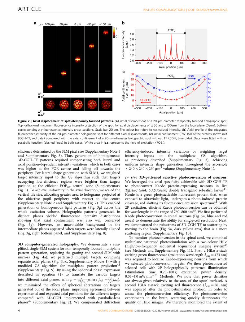
efficiency determined by the SLM pixel size (Supplementary Note 1and Supplementary Fig. 3). Thus, generation of homogeneous3D-CGH-TF patterns required compensating both lateral andaxial position-dependent intensity variations, which in both caseswas higher at the FOE centre and falling off towards theperiphery. For lateral shape generation with SLM1, we weightedtarget intensity input to the GS algorithm such that targetsoccupying low-efficiency regions were brighter than targetsposition at the efficient FOEx,y central zone (SupplementaryFig. 3). To achieve uniformity in the axial direction, we scaled thevertical tile size, allocating greater area to holograms projected atthe objective pupil periphery with respect to the centre(Supplementary Note 2 and Supplementary Fig. 7). This enabledgeneration of homogeneous light patterns (Fig. 3g) across thewhole excitation volume. Holographic patterns generated indistinct planes yielded fluorescence intensity distributionsshowing that axial confinement was also well conserved(Fig. 3g). However, an unavoidable background in theintermediate planes appeared when targets were laterally aligned(Fig. 3g, right bottom panel, and Supplementary Fig. 8).
3D computer-generated holography. We demonstrate a sim-plified, single-SLM system for non-temporally focused multiplanepattern generation, replacing the grating and second SLM withmirrors (Fig. 4a); we patterned multiple targets occupyingseparate axial planes (Fig. 4b,c, Supplementary Movie 1) with amodified GS algorithm for multiplane pattern projection41
(Supplementary Fig. 9). By using the spherical phase expressiondescribed in equation (1) to translate the various targetsinto different axial planes, with r ¼ r
NA�feq1ðwhere feq1 ¼ f1f3
f2f4fobjÞ,
we minimized the effects of spherical aberrations on targetsgenerated out of the focal plane, improving agreement betweenexperimental and expected axial positions for the different targetscompared with 3D-CGH implemented with parabolic-lensphases42 (Supplementary Fig. 2). We compensated diffraction
efficiency-induced intensity variations by weighting targetintensity inputs to the multiplane GS algorithm,as previously described (Supplementary Fig. 3), achievinguniform intensity shape generation throughout the accessibleB240� 240� 260 mm3 volume (Supplementary Note 1).
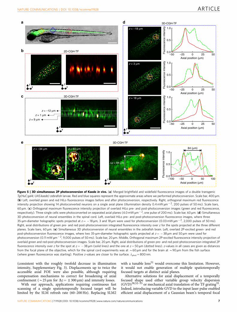
In vivo 3D-patterned selective photoconversion of neurons.We leveraged the axial specificity achievable with 3D-CGH-TFto photoconvert Kaede protein-expressing neurons in liveTg(HuC:Gal4; UAS:Kaede) double transgenic zebrafish larvae43.Kaede is a green photoactivable fluorescent protein that, whenexposed to ultraviolet light, undergoes a photo-induced proteincleavage, red shifting its fluorescence emission spectrum44. With2P excitation, efficient Kaede photoconversion can be obtainedfor wavelengths in the range of 760–800 nm45. We first performedKaede photoconversion in spinal neurons (Fig. 5a, blue and redareas) to demonstrate the ability for single-cell resolution. Next,we demonstrated the robustness of 3D-CGH-TF to scattering bymoving to the brain (Fig. 5a, dark yellow area) that is a morescattering region (Supplementary Fig. 10).
To monitor photoconversion in the spinal cord, we combinedmultiplane patterned photostimulation with a two-colour HiLo(high/low-frequency sequential acquisition) imaging system46
(see Methods and Supplementary Fig. 11). First, a HiLo z-stackexciting green fluorescence (excitation wavelength lexc¼ 473 nm)was acquired to localize Kaede-expressing neurons from whichwe selected photoconversion targets. We then photoconvertedselected cells with 2P holographically patterned illumination(stimulation time 0.20–100 s; excitation power density:0.03–4.0 mW mm� 2; Methods. We note that power densitiesare always given relatively to the area of the spots’ surface). Asecond HiLo z-stack exciting red fluorescence (lexc¼ 561 nm)was acquired after the photostimulation protocol in order toassess the photoconversion efficiency. For photoconversionexperiments in the brain, scattering quickly deteriorates thequality of HiLo images. We therefore monitored the extent of
100 μmz = 50 μm 0 μm –50 μm –100 μm
1
01.0
0.8
0.6
0.4
0.2
0.0
30
25
20
15
10
0
CGH-TF5
–300 –200 –100 0 100 200 300
–300 –200 –100 0 100
CGG70
60
50
40
30
20
10
0200 300
Axial position (μm)
Axi
al c
onfin
emen
tF
WH
M (
μm)
Flu
ores
cenc
e in
tens
ity(a
.u.)
FOEz
FOEz
Axial position (μm)
zy
xy
a b
c
Figure 2 | Axial displacement of spatiotemporally focused patterns. (a) Axial displacement of a 20-mm-diameter temporally focused holographic spot.
Top, orthogonal maximum fluorescence intensity projection of the spot, for axial displacements of ±50 and±100mm from the focal plane (0mm). Bottom,
corresponding x–y fluorescence intensity cross-sections. Scale bar, 20mm. The colour bar refers to normalized intensity. (b) Axial profile of the integrated
fluorescence intensity of the 20-mm-diameter holographic spot for different axial displacements. (c) Axial confinement (FWHM) of the profiles shown in b
(CGH-TF; red data) compared with the axial confinement of a 20-mm-diameter holographic spot without TF (CGH; blue data). Data were fitted with a
parabolic function (dashed lines) in both cases. White area in b,c represents the field of excitation (FOEz).
ARTICLE NATURE COMMUNICATIONS | DOI: 10.1038/ncomms11928
4 NATURE COMMUNICATIONS | 7:11928 | DOI: 10.1038/ncomms11928 | www.nature.com/naturecommunications
Pla
ne APla
ne A
Pla
ne B
Pla
ne B
Pla
ne A
Pla
ne B
SLM
1S
LM 2
xy
x
�
–�0
y
xy
zy
z
1
0
0.2
1.0
x
z
8 2.01
01.5
1.0
0.52 4 6 8 10 12
Hologram width (mm)
Aut
ocor
rela
tion
wid
thF
WH
M (
μm)
7
6
5
1.0
0.5
0.0–100 –50 50 100
Axial position (μm)0 –100 –50 50 100
Axial position (μm)0 –100 –50 50 100
Axial position (μm)0
–100 –50 50 100Axial position (μm)
0–100 –50 50 100Axial position (μm)
0
0 2 4 6 8 10 12
Δx
Δy
σxσy
12 mm 10 mm 8 mm
Hologram width (mm)
Flu
ores
cenc
ein
tens
ity (
a.u.
)
1.0
0.5
0.0
Flu
ores
cenc
ein
tens
ity (
a.u.
)
1.0
0.5
0.0
Flu
ores
cenc
ein
tens
ity (
a.u.
)
1.0
0.5
0.0
Flu
ores
cenc
ein
tens
ity (
a.u.
)
1.0
0.5
0.0
Flu
ores
cenc
ein
tens
ity (
a.u.
)
Axi
al c
onfin
emen
tF
WH
M (
μm)
x
a b
c
d e f
g
6 mm 2 mm4 mm
Figure 3 | Multiplane spatiotemporally focused pattern generation. (a) Top, tiled phase profiles addressed to SLM1 for encoding the words ‘neuro’ (plane
A) and ‘photonics’ (plane B). Bottom, Fresnel lens-phase profiles addressed to SLM2 to axially displace each holographic pattern generated by SLM1 on
separated planes at þ 20mm (plane A) and � 20mm (plane B). (b) Left, x–y 2P fluorescence intensity cross-sections at planes A and B generated by the
holograms in a. Right, orthogonal maximum 2P intensity projection along x (top) and y (bottom). (c) Orthogonal fluorescence intensity projection of
spatiotemporally focused patterns created by projecting 20-mm-diameter holographic spots in one, two, three and four planes at positions laterally shifted
and in four planes at positions axially aligned (from left to right). Scale bars, 20mm. (d) Axial confinement (FWHM) of a 20-mm-diameter holographic spot
for different hologram widths, tested in both directions, Dx (blue data) and Dy (red data) parallel and perpendicular to grating’s dispersion, respectively.
(e) x–y 2P fluorescence intensity cross-sections of a 20-mm-diameter holographic spot generated with different hologram widths Dy. (f) Autocorrelation
width at the sample plane of a 20-mm-diameter holographic spot as a function of the hologram width along the x- (blue data; sx) and y directions (red data;
sy). (g) Axial profile of the integrated fluorescence intensity of the holographic spots shown on c. Colour bars refer to normalized intensity.
NATURE COMMUNICATIONS | DOI: 10.1038/ncomms11928 ARTICLE
NATURE COMMUNICATIONS | 7:11928 | DOI: 10.1038/ncomms11928 | www.nature.com/naturecommunications 5
photoconversion by moving the sample to a 2P galvo-basedscanning imaging system in another set-up (see Methods). Greenand red fluorescence in the 2P imaging system were excited at780 nm, and scanning was performed at 0.74 Hz.
In the spinal cord, we first used 2D-CGH-TF to demonstratesimultaneous photoconversion (lphot¼ 800 nm) of multipleneurons in a single plane with cellular precision (Fig. 5a,b).Then, we used 3D-CGH-TF to photoconvert isolated neurons(Fig. 5c) or groups of multiple neurons (Fig. 5d) in distinct axialplanes. The axial confinement achievable with 3D-CGH-TFenabled single-layer selectivity that would otherwise not bepossible using CGH deprived of TF (Supplementary Fig. 12a).In all experiments performed, photoconversion induced aB10-fold increase in the ratio of pre- and post-photoconversionred fluorescence.
To demonstrate in-depth photoconversion, we performed asecond set of experiments in the brain of zebrafish larvae byphotoconverting neuronal ensembles in two different axial planesusing 35-mm-diameter temporally focused holographic spotsseparated by B80 mm (Fig. 5e), with the first plane positionedat B90 mm from the surface. Although the axial confinementdeteriorates with depth because of scattering, the red fluorescenceintensity profiles along the axial direction showed selective andefficient photoconversion (Fig. 5d,e), which was not achievablewith 3D-CGH alone (Supplementary Fig. 12b). Strikingly, axialresolution and overall shape were also preserved despite lightpropagation through the zebrafish brain (Supplementary Fig. 10).In agreement with previous results in rats23,24, these resultsdemonstrate that TF enables robust in-depth propagation ofshaped patterns through scattering media.
It is important to note that 2P Kaede photoconversion is alow-efficiency process and requires relatively high illuminationdoses (B0.04–4 mW mm� 2) and long (from 200 ms to a fewhundreds of seconds) stimulation protocols. Other type ofapplications such as activation of neurons via 2P-mediatedoptogenetic stimulation can work with drastically reduced
photostimulation time (5 pulses of 50 ms), as well as lowerillumination doses (0.04–0.60 mWmm� 2; Supplementary Note 3).
A still open question for multiplane multispot photo-stimulation concerns the possible temperature rise induced bylaser illumination. For the illumination doses we used in theoptogenetics experiments (Supplementary Note 3), we estimatedthat this does not exceed few degrees Celsius. Specifically, bysolving the heat diffusion equation47 with typical thermal opticalparameters of tissue found in literature48–50, we estimated themean temperature rise to be of the order of 0.06–0.25 �C, usingillumination pulses of 50 ms in the range of 0.04–0.6 mW mm� 2
and a 10-mm diameter spot (Picot et al., private communication).Using 10 spots of the same size distributed randomly over a FOEof 100� 100 mm2 would generate a mean temperature rise of0.9–3.7 �C. Diffusion over the tissue volume enables thetemperature to return to its equilibrium value in less than150 ms, which was the interval between illumination pulses (Picotet al., private communication).
DiscussionWe have demonstrated a unique optical system enabling remoteaxial displacement of temporally focused holographic patterns, aswell as generation of multiple temporally focused holographictargets occupying separate axial planes. In our two-step system,the first SLM is addressed with phase holograms controlling thetransverse target light distribution. The second SLM, positionedafter the TF grating, is addressed with Fresnel lens-phasefunctions and controls target axial position. We demonstratedthat this configuration can jointly translate single or multiplespatiotemporally focused patterns across the sample volume.
We demonstrated axial displacement of a single temporallyfocused holographic pattern across an axial range (±300mm),roughly two times greater than the nominal accessible axial FOE,FOEz (±130mm). For axial shifts of Dzj j � FOEZ=2, spotshape and axial resolution (5–10 mm) were well conserved,while fluorescence intensity decreased approximately fivefold
z = 130 μm
z = 65 μm
z = 0 μm
z = –65 μm
Ti:Sapphire laser
BE SLM1
CL
L1
L2
L3L4OBJ1OBJ2CCD L5 FFP
M
M
z = 130 μm
μm
μm
μm
150
100
50
–50
–100
–150z x
y
0
–50
–50
500
0
a c
b
Figure 4 | 3D-CGH. (a) Schematic of the optical set-up for 3D-CGH. In this case the diffraction grating G and SLM2 were replaced by mirrors.
(b) 2P fluorescence images of 3D-CGH patterns, depicting the letters ‘a’, ‘b’ and ‘c’ at three different axial positions, z¼ 130mm, 0 and � 130mm,
respectively. The phase profile used to project these patterns was calculated using a multiplane GS algorithm (Supplementary Fig. 9). Weighting of the
input patterns according to their lateral and axial position (Supplementary Fig. 3) enabled diffraction efficiency correction and generated equal-intensity
light patterns. (c) Volumetric reconstruction of three-dimensional distribution of 5-mm-diameter holographic spots (see also Supplementary Movie 1).
ARTICLE NATURE COMMUNICATIONS | DOI: 10.1038/ncomms11928
6 NATURE COMMUNICATIONS | 7:11928 | DOI: 10.1038/ncomms11928 | www.nature.com/naturecommunications
(consistent with the roughly twofold decrease in illuminationintensity, Supplementary Fig. 3). Displacements up to twice theaccessible axial FOE were also possible, although requiringcompensation mechanisms to correct for broadening of axialconfinement (B25 mm for Dz¼±300 mm) and intensity losses.
With our approach, applications requiring continuous fastscanning of a single spatiotemporally focused target will belimited by the SLM refresh rate (60–200 Hz). Replacing SLM2
with a tunable lens51 would overcome this limitation. However,it would not enable generation of multiple spatiotemporallyfocused targets at distinct axial planes.
Alternative solutions for axial displacement of a temporallyfocused shape used either variable group velocity dispersion(GVD)38,52–55 or mechanical axial translation of the TF grating35.Indeed, introducing variable GVD to the input laser pulse enabledefficient axial displacement of a Gaussian beam’s temporal focal
1.0
0.5
0.0–50 50
Axial position (μm)
Flu
ores
cenc
e in
tens
ity
–25 250
1.0
0.5
0.0–50 50
Axial position (μm)
Flu
ores
cenc
e in
tens
ity
–25 250
1.0
0.5
0.0–50 50
Axial position (μm)
84 (μm)
3D-CGH-TF
3D-CGH-TF
2D-CGH-TF
zx
zx
zx
yx
yx
yx
Δz = 84 μm
z = 18 μm
z = 3 μm
z = –18 μm
z = 50 μmz = –34 μm
z = 1 μm
z = 9 μm
z = –12 μm
3D-CGH-TF
Flu
ores
cenc
e in
tens
ity
–25 250
1.0
0.5
0.0–100 –50 50
Axial position (μm)
Flu
ores
cenc
e in
tens
ity
1000
a
b
c
d
e
Figure 5 | 3D simultaneous 2P photoconversion of Kaede in vivo. (a) Merged brightfield and widefield fluorescence images of a double transgenic
Tg(HuC:gal4; UAS:kaede) zebrafish larvae. Red and blue squares represent the approximate areas where we performed photoconversion. Scale bar, 400mm.
(b) Left, overlaid green and red HiLo fluorescence images before and after photoconversion, respectively. Right, orthogonal maximum red fluorescence
intensity projection showing 14 photoconverted neurons on a single axial plane (illumination density 0.4 mW mm� 2, 200 pulses of 50 ms). Scale bars,
60mm. (c) Orthogonal maximum fluorescence intensity projection of overlaid HiLo pre- and post-photoconversion images (green and red fluorescence,
respectively). Three single cells were photoconverted on separated axial planes (4.0 mWmm� 2, one pulse of 200 ms). Scale bar, 60mm. (d) Simultaneous
3D photoconversion of neural ensembles in the spinal cord. Left, overlaid HiLo pre- and post-photoconversion fluorescence images, where three
35-mm-diameter holographic spots projected at z¼ � 18mm, 3 and 18mm were used for photoconversion (0.03 mW mm� 2, 2,000 pulses of 50 ms).
Right, axial distributions of green pre- and red post-photoconversion integrated fluorescence intensity over z for the spots projected at the three different
planes. Scale bars, 60 mm. (e) Simultaneous 3D photoconversion of neural ensembles in the zebrafish brain. Left, overlaid 2P-excited green- and red
post-photoconversion fluorescence images, where two 35-mm-diameter holographic spots projected at z¼ � 38mm and 50mm were used for
photoconversion (0.11 mWmm� 2, 9,000 pulses of 50 ms). Scale bar, 20mm. Middle, Orthogonal maximum 2P-excited fluorescence intensity projection of
overlaid green and red-post-photoconversion images. Scale bar, 20mm. Right, axial distributions of green pre- and red post-photoconversion integrated 2P
fluorescence intensity over z for the spot at z¼ � 38 mm (solid lines) and the one at z¼ 50mm (dotted lines). z-values in all cases are given as distances
from the focal plane of the objective, which for the spinal cord experiments was at B60mm and for the brain at B90mm from the fish surface
(where green fluorescence was starting). Positive z-values are closer to the surface. lphot¼800 nm.
NATURE COMMUNICATIONS | DOI: 10.1038/ncomms11928 ARTICLE
NATURE COMMUNICATIONS | 7:11928 | DOI: 10.1038/ncomms11928 | www.nature.com/naturecommunications 7
plane. However, GVD-induced axial displacement stronglydepends on the autocorrelation width of the illuminationpatterns, which for holographic spots is small due to speckles.Therefore, in order to achieve axial displacement of temporallyfocused holographic patterns, spatial filtering is required toincrease the correlation width. However, this degrades spatialresolution and decreases illumination intensity38. Furthermore,the GVD approach achieved axial displacements of only a fewmicrons38. Greater scanning ranges could be obtained bycombining 2D-CGH with the optical design proposed by Danaet al.35 for axial scanning of a temporally focused line. The systemimplemented on-axis-light propagation and mechanical axialtranslation of the TF grating. However, for high-magnification(M) objectives, the axial shift, d, was limited by the long requiredgrating translation, Dpd�M2. Thus, the maximum shiftachieved with a � 40 objective was inferior to 30 mm.
In addition to limited range, neither GVD shift nor gratingtranslation enable the generation of multiple temporally focusedtargets at distinct axial planes. Here we overcome this limitationwith a two-step, two-SLM system, addressing a first SLM withmultiple vertically tiled phase holograms, each encoding the lightdistribution of a single plane, and a second SLM with an equalnumber of Fresnel lens phases, which individually control theaxial position for each plane. In this way, all targets are projectedto the TF plane, which is kept at a fixed position, while the secondSLM imposes the spatial wavefront curvature needed to displaceeach plane axially.
The number of spatiotemporal focal planes that can begenerated with this design is a tradeoff between the number ofavailable pixels and spatial resolution. Here we demonstratedgeneration of up to four spatiotemporal focal planes. In this case,the vertical spatial resolution (that is, the average speckle size inthe y axis), where tiling occurs, decreases roughly twofold becauseof the reduced size of the hologram at the objective back aperture.LCOS-SLM devices with increased number of pixels shouldincrease the number of achievable planes and reduce hologramresolution deterioration.
Moreover, we implemented a simpler single-SLM system togenerate multiplane CGH light patterns without TF. Althoughthis approach has a poor axial confinement with respect to3D-CGH-TF, it could still be a powerful method for applicationsusing sparsely expressing samples. Previous schemes for multi-plane generation of laterally extended shapes through high-NAobjectives reported patterns spanning a limited (tens of microns)axial range27,30,31 and used linear excitation. Here we exploitedthe whole excitation volume reachable with the LCOS-SLMusing high-NA objectives. This was achieved by minimizingspherical aberration of targets generated out of the nominalobjective focal plane by accounting for the high-NA objective inthe expression of the Fresnel lens-phase profile. In addition,throughout the accessible volume, we obtained uniform lightdistribution among the target shapes. Weighting the amplitude ofeach target input to the GS algorithm according to positionenabled compensation of intensity loss because of diffractionefficiency, which decreases with increasing distance from theexcitation volume centre.
We demonstrated the capabilities of the 3D-CGH-TF systemby performing multiplane 2P photoconversion of Kaede-expressing neurons. Previous in vivo experiments photo-converting Kaede in single neurons of zebrafish larvaeused one-photon visible light illumination43,56,57. Here wedemonstrated 2P-mediated single-cell resolution simultaneousphotoconversion of multiple Kaede-expressing neurons. Theunprecedented spatial precision achieved by our approach can,in the future, be extended to track the morphology of singleneurons across the entire nervous system of the zebrafish larva.
For multiplane photoconversion of multiple isolated targets(for instance, in sparsely expressing samples), 3D-CGH holds anadvantage over 3D-CGH-TF by enabling light shaping in agreater number of planes. However, 3D-CGH-TF enables a betteraxial confinement, a key parameter for experiments requiringillumination of spatially nearby multiple targets or large areas.Moreover, generation of multiplane illumination patterns with3D-CGH also produces spurious light in the intermediate planesabsent in illumination geometries produced with 3D-CGH-TF. Inaddition, we have previously demonstrated that TF is particularlyrobust to scattering making 3D-CGH-TF more suitable than3D-CGH for applications requiring in-depth illuminationthrough scattering media23,24.
The same optical design could be used to photoswitch otherproteins such as photactivatable green fluorescent protein58 orkindling fluorescent protein (KFP1)59 to precisely track the 3Dposition of specific cells in vivo during embryo development.Combined with optogenetics (Supplementary Note 3) oruncaging, multiplane generation of spatiotemporally focusedpatterns will enable simultaneous control of neurons andsubstructures in different planes, as well as provide a flexiblemean to stimulate locations lying above or below the imagingplane. Combined with extended depth-of-field imaging60,multiplane light patterning could also improve the spatialspecificity of functional voltage or calcium physiology byshaping light on cells or structures of interest61.
In this study, the two-SLM system is combined with HiLoimaging. Combining this approach with 2P imaging would alsoenable deep photostimulation and imaging in vivo. Decoupling oflateral and axial wavefront shaping could also be adopted inoptical designs different from the one presented here. Forexample, placing a second SLM at the Fourier plane of a fastswitchable array should enable 3D-encoded multisite 2P micro-scopy62 or high-speed 3D holographic light patterning63.
MethodsTwo-SLM optical set-up. The optical system, schematically depicted in Fig. 1 andSupplementary Fig. 11, was built around a commercial Olympus IX71 invertedmicroscope, modified in order to accommodate two opposite-facing objectives,OBJ1 and OBJ2, for excitation and fluorescence collection, respectively. To thisend, the condenser lens of the microscope was substituted with a dielectric mirrorand an Olympus LUMPLFL60xW/IR2, NA 0.90 objective (OBJ1). The expanded(� 10) beam of a Ti:Sapphire laser (MaiTai Deep-See, Spectra-Physics) covered theactive area of a first LCOS-SLM (X10468-07, Hamamatsu Photonics; SLM1), whichmodulated the phase of the incoming beam to create a first image of the desiredintensity pattern on the diffraction grating (830 l/mm, 53004ZD02-035R,Richardson Gratings; G) for TF through the lens L1 (f1¼ 500 mm). 2D-phaseholograms were calculated using a standard GS algorithm20,33. The first diffractionorder was subsequently collimated by lens L2 (f2¼ 500 mm) and impinged on asecond SLM (X10468-07, Hamamatsu Photonics; SLM2), which was imaged at theback focal plane of the excitation objective, OBJ1, via a 2:1 telescope (lenses L3,f3¼ 1,000 mm and L4, f4¼ 500 mm). Suppression of the zero-order spot arisingfrom SLM1 was achieved by using two cylindrical lenses (fL1¼ 1,000 mm andfL2¼ � 1,000 mm) oriented at þ 45� and � 45� with respect to the gratinglines64.
Holographic light patterns generated at the sample volume illuminated a thinspin-coated fluorescent layer of rhodamine-6G in polymethyl methacrylate 2% w/vin chloroform and the induced fluorescence was imaged on a CCD camera(CoolSNAP HQ2, Roper Scientific) through OBJ2 (Olympus UPLSAPO60XW,NA 1.2). For 3D reconstruction of illumination volumes, OBJ2 was fixed andfocused on the fluorescent layer, while OBJ1 was moved along the axial directionwith a piezo positioner of 1 mm range when working in closed loop (PI N-725.2APIFOC). The two SLMs, the CCD camera, the piezo positioner, lasers and otherelectronic components of the set-up were controlled by a custom-developedinterface in LabVIEW. GS-based algorithms were run in MATLAB.
When the set-up was used for generation of multiplane holographic patterns(not temporally focused) a mirror replaced the diffraction grating, and SLM2 waseither used in reflectance mode by applying only the flatness correction phase maskof the device or was replaced by a mirror. Both the grating and SLM2 weremounted on magnetic bases enabling fast switching between the differentconfigurations. The multiplane GS algorithm used in this case was run in acustom-designed Cþ þ software interface, Wavefront Designer20.
ARTICLE NATURE COMMUNICATIONS | DOI: 10.1038/ncomms11928
8 NATURE COMMUNICATIONS | 7:11928 | DOI: 10.1038/ncomms11928 | www.nature.com/naturecommunications
Two-colour HiLo imaging system. High-resolution multiplane fluorescenceimaging of zebrafish larvae was achieved by coupling an optical set-up fortwo-colour HiLo microscopy46 to the Olympus IX71 microscope. Two continuouswave 473-nm (Laser Quantum, Ciel 350 mW) and 561-nm (CNI laser,MGL-N-561-500 mW) lasers were co-aligned in the same optical path with thedichroic mirror D2 (Semrock, Di02-R514) and collimated with lenses L6(f6¼ 125 mm), L7 (f7¼ 150 mm) and L10 (f10¼ 35 mm) to illuminate an oscillatingdiffuser plate (Optotune LSR-3005-10) that was imaged through lenses L8(f8¼ 75 mm) and L9 (f9¼ 200 mm) at the back aperture of the excitation objective,OBJ1 (Supplementary Fig. 11). The D1 dichroic mirror reflected the collectedfluorescence to a CMOS camera (Hamamatsu Photonics, Orca Flash 4.0-V2)through the appropriate filter cube (FC2) for green (dichroic mirror SemrockFF495-Di02, emission filter Semrock FF01-520/35-25) or red fluorescence (dichroicmirror Semrock Di02-R561, emission filter Semrock FF595-Di02).
The sectioned image was computed with custom scripts written in MATLAB65.The cutoff frequency used to merge the low- and high-frequency components waschosen such as kcE0.1 klow, where klow is the frequency of the low-pass filterapplied to the uniform illumination image. With those parameters, we measured anaxial resolution of 3.2-mm FWHM for the emitted fluorescence (SupplementaryFig. 11b). The axial resolution was measured using a Rhodamine-6G thin layer.First, we recorded a z-stack with uniform illumination (oscillating diffuser on) andthen with speckle illumination (oscillating diffuser off). The two stacks were thenprocessed in MATLAB to generate an axially resolved HiLo z-stack usingalgorithms previously described34,65. The axial resolution shown in SupplementaryFig. 11 is the axial resolution measured on the processed HiLo z-stack.
2P galvo-based scanning imaging system. 2P imaging of photoconvertedzebrafish larvae in the brain performed by a mode-locked Ti-Sapphire laser source(Coherent Chameleon Vision II, pulse width 140 fs, tuning range 680–1,080 nm).The femtosecond pulsed beam was raster-scanned on the sample via a pair of xygalvanometric mirrors (3 mm aperture, 6215H series, Cambridge Technology)imaged at the back aperture of the microscope objective (� 40 W APO NIR,Nikon) through an afocal telescope (scan lens: f¼ 100 mm, tube lens: f¼ 300 mm).Galvanometric mirrors were driven by two servo drivers (MicroMax series 671,Cambridge Technology) controlled by a Digital/Analog converter board(PCI-6110, National Instrument). Emitted fluorescence was collected by a fibre-coupled detection scheme66. The fibre exit was imaged on two photomultipliertubes GaAsP (H10770-40 SEL, Hamamatsu Photonics, active area 5 mm) by a setof three matching asphere lenses (f¼ 23.5 mm, Melles Griot #LAG-32.5-23.5-C).Following the fibre exit, fluorescence light was filtered with an infrared-light-blocking filter (FF01-750sp, Semrock), split into two channels by a dichroic mirror(FF555-Di03, Semrock) and detected through two emission filters (FF01-510/84and FF02-617/73, Semrock). The whole system was built around a commercialupright microscope (SliceScope, Scientifica). 2P imaging laser power was tunedby combining an electrically controlled liquid crystal variable phase retarder(LRC-200-IR1, Meadowlark Optics) and a polarizer cube (BB-050-IR1,Meadowlark Optics) at the exit of the laser source.
Green and red fluorescence z-stacks of photoconverted Kaede in the zebrafishbrain were acquired by scanning the excitation beam (780 nm) at 0.74 Hz (fullframe) and averaging 10–20 frames for each plane.
Photoconversion protocol. First, a HiLo z-stack in the green channel(200� 200� 100mm3) was recorded to map the location of neuronal cells forphotoconversion. On the basis of these images, we calculated phase holograms thatproduced the corresponding 2D or 3D illumination patterns. We typically used 5-mm-diameter holographic spots to target single cells and 30–35-mm-diameterholographic spots to target sets of neurons. In order to quantify the efficiency ofphotoconversion, we also recorded the corresponding z-stack in the red channelbefore photoconversion.
Simultaneous 2P photoconversion (lphot¼ 800 nm) of all targets was performedwhile monitoring the fluorescence in the red channel. We typically observed atenfold increase of red fluorescence in the targeted cells. Photoconversion duringfluorescence imaging was minimized by keeping the total acquisition time below2 min and laser power at the sample plane below 20 mW. To minimize thermaldamage during photoconversion, we delivered trains of 50-ms pulses, low laserintensity B0.04–4.0 mW mm� 2 (power densities are always given relatively to thearea of the spots’ surface) for periods of time that ranged from 200 ms to a fewhundred seconds depending on the laser intensity.
Transgenic lines. Experiments were performed on Danio rerio larvae between 2and 6 days post fertilization following procedures approved by the InstitutionalEthics Committee Darwin in the ‘Institut du Cerveau et de la Moelle epiniere’(ICM). AB and TL strains of wild-type (WT) larvae were obtained fromlaboratory’s stock of adults. Embryos and larvae were raised in an incubator at28.5 �C until shortly before recordings were performed. For photoconversionexperiments, we used Tg(HuC:gal4; UAS:kaede)43 where the HuC promoter drivespan-neuronal expression of Gal4 and Kaede at the larval stage. Tg(pkd2l1:gal4;UAS:ChR2-H134R-mCherry; UAS:GCaMP5G)65,67 were used for combination ofoptogenetics and calcium imaging in Supplementary Data. Before performing
image acquisitions, embryos were dechorionated and screened for fluorescence at 1days post fertilization. Larvae screened for Kaede fluorescence were later embeddedlaterally in 1.5% agarose. Larvae were anaesthetized in 0.02% tricain (MS-222,Sigma-Aldrich, USA).
Data availability. The data that support the findings of this study are availablefrom the corresponding author upon request.
References1. Denk, W., Strickler, J. H. & Webb, W. W. Two-photon laser scanning
fluorescence microscopy. Science 248, 73–76 (1990).2. Salome, R. et al. Ultrafast random-access scanning in two-photon microscopy
using acousto-optic deflectors. J. Neurosci. Methods 154, 161–174 (2006).3. Reddy, G. D., Kelleher, K., Fink, R. & Saggau, P. Three-dimensional random
access multiphoton microscopy for functional imaging of neuronal activity.Nat. Neurosci. 11, 713–720 (2008).
4. Grewe, B. F., Langer, D., Kasper, H., Kampa, B. M. & Helmchen, F. High-speedin vivo calcium imaging reveals neuronal network activity with near-millisecond precision. Nat. Methods 7, 399–405 (2010).
5. Nguyen, Q. T., Callamaras, N., Hsieh, C. & Parker, I. Construction of atwo-photon microscope for video-rate Ca2þ imaging. Cell Calcium 30,383–393 (2001).
6. Oron, D., Tal, E. & Silberberg, Y. Scanningless depth-resolved microscopy. Opt.Express 13, 1468–1476 (2005).
7. Zhu, G., van Howe, J., Durst, M., Zipfel, W. & Xu, C. Simultaneous spatial andtemporal focusing of femtosecond pulses. Opt. Express 13, 2153–2159 (2005).
8. Akturk, S., Gu, X., Bowlan, P. & Trebino, R. Spatio-temporal couplings inultrashort laser pulses. J. Opt. 12, 093001 (2010).
9. Tal, E., Oron, D. & Silberberg, Y. Improved depth resolution in video-rateline-scanning multiphoton microscopy using temporal focusing. Opt. Lett. 30,1686–1688 (2005).
10. Vaziri, A. & Shank, C. V. Ultrafast widefield optical sectioning microscopy bymultifocal temporal focusing. Opt. Express 18, 19645–19655 (2010).
11. Isobe, K. et al. Enhancement of lateral resolution and optical sectioningcapability of two-photon fluorescence microscopy by combining temporal-focusing with structured illumination. Biomed. Opt. Express 4, 2396–2410(2013).
12. Choi, H. et al. Improvement of axial resolution and contrast in temporallyfocused widefield two-photon microscopy with structured light illumination.Biomed. Opt. Express 4, 995–1005 (2013).
13. Song, Q. et al. Two-dimensional spatiotemporal focusing of femtosecond pulsesand its applications in microscopy. Rev. Sci. Instrum. 86, 083701 (2015).
14. Losonczy, A., Zemelman, B. V, Vaziri, A. & Magee, J. C. Network mechanismsof theta related neuronal activity in hippocampal CA1 pyramidal neurons. Nat.Neurosci. 13, 967–972 (2010).
15. Dana, H. et al. Hybrid multiphoton volumetric functional imaging oflarge-scale bioengineered neuronal networks. Nat. Commun. 5, 3997 (2014).
16. Vaziri, A., Tang, J., Shroff, H. & Shank, C. V. Multilayer three-dimensionalsuper resolution imaging of thick biological samples. Proc. Natl Acad. Sci. USA105, 20221–20226 (2008).
17. Kim, D. & So, P. T. C. High-throughput three-dimensional lithographicmicrofabrication. Opt. Lett. 35, 1602–1604 (2010).
18. Andrasfalvy, B. K., Zemelman, B. V, Tang, J. & Vaziri, A. Two-photonsingle-cell optogenetic control of neuronal activity by sculpted light. Proc. Natl.Acad. Sci. USA 107, 11981–11986 (2010).
19. Rickgauer, J. P., Deisseroth, K. & Tank, D. W. Simultaneous cellular-resolutionoptical perturbation and imaging of place cell firing fields. Nat. Neurosci. 17,1816–1824 (2014).
20. Lutz, C. et al. Holographic photolysis of caged neurotransmitters. Nat. Methods5, 821–827 (2008).
21. Papagiakoumou, E., de Sars, V., Oron, D. & Emiliani, V. Patterned two-photonillumination by spatiotemporal shaping of ultrashort pulses. Opt. Express 16,22039–22047 (2008).
22. Papagiakoumou, E. et al. Scanless two-photon excitation of channelrhodopsin-2.Nat. Methods 7, 848–854 (2010).
23. Begue, A. et al. Two-photon excitation in scattering media by spatiotemporallyshaped beams and their application in optogenetic stimulation. Biomed. Opt.Express 4, 2869–2879 (2013).
24. Papagiakoumou, E. et al. Functional patterned multiphoton excitation deepinside scattering tissue. Nat. Photon. 7, 274–278 (2013).
25. Piestun, R., Spekor, B. & Shamir, J. Wave fields in three dimensions: analysisand synthesis. J. Opt. Soc. Am. A 13, 1837–1848 (1996).
26. Curtis, J. E., Koss, B. A. & Grier, D. G. Dynamic holographic optical tweezers.Opt. Commun. 207, 169–175 (2002).
27. Sinclair, G. et al. Interactive application in holographic optical tweezers of amulti-plane Gerchberg-Saxton algorithm for three-dimensional light shaping.Opt. Express 12, 1665–1670 (2004).
NATURE COMMUNICATIONS | DOI: 10.1038/ncomms11928 ARTICLE
NATURE COMMUNICATIONS | 7:11928 | DOI: 10.1038/ncomms11928 | www.nature.com/naturecommunications 9
28. Yang, S. et al. Three-dimensional holographic photostimulation of the dendriticarbor. J. Neural Eng. 8, 46002 (2011).
29. Anselmi, F., Ventalon, C., Begue, A., Ogden, D. & Emiliani, V. Three-dimensional imaging and photostimulation by remote-focusing andholographic light patterning. Proc. Natl Acad. Sci. USA 108, 19504–19509(2011).
30. Hilario, P. L., Villangca, M. J. & Tapang, G. Independent light fields generatedusing a phase-only spatial light modulator. Opt. Lett. 39, 2036–2039 (2014).
31. Ma, B. et al. Generation of three-dimensional optical structures by dynamicholograms displayed on a twisted nematic liquid crystal display. Appl. Phys. B110, 531–537 (2013).
32. Emiliani, V. et al. Wave front engineering for living cells microscopy. Opt.Express 13, 1395–1405 (2005).
33. Gerchberg, R. W. & Saxton, W. O. A pratical algorithm for the determination ofthe phase from image and diffraction pictures. Optik (Stuttg) 35, 237–246(1972).
34. Zahid, M. et al. Holographic photolysis for multiple cell stimulation in mousehippocampal slices. PLoS ONE 5, e9431 (2010).
35. Dana, H. & Shoham, S. Remotely scanned multiphoton temporal focusing byaxial grism scanning. Opt. Lett. 37, 2913–2915 (2012).
36. Richards, B. & Wolf, E. Electromagnetic diffraction in optical systems. II.Structure of the image field in an aplanatic system. Proc. R Soc. Lond. A 253,358–379 (1959).
37. Botcherby, E. J., Juskaitis, R., Booth, M. J. & Wilson, T. Aberration-free opticalrefocusing in high numerical aperture microscopy. Opt. Lett. 32, 2007–2009(2007).
38. Leshem, B., Hernandez, O., Papagiakoumou, E., Emiliani, V. & Oron, D. Whencan temporally focused excitation be axially shifted by dispersion? Opt. Express22, 7087–7098 (2014).
39. Dainty, J. C. Laser Speckle and Related Phenomena. Topics in Applied Physics 9(Springer-Verlag, 1975).
40. Matar, S., Golan, L. & Shoham, S. Reduction of two-photon holographic speckleusing shift-averaging. Opt. Express 19, 25891–25899 (2011).
41. Haist, T., Schonleber, M. & Tiziani, H. Computer-generated holograms from3D-objects written on twisted-nematic liquid crystal displays. Opt. Commun.140, 299–308 (1997).
42. Leach, J. et al. Interactive approach to optical tweezers control. Appl. Opt. 45,897–903 (2006).
43. Scott, E. K. et al. Targeting neural circuitry in zebrafish using GAL4 enhancertrapping. Nat. Methods 4, 323–326 (2007).
44. Ando, R., Hama, H., Yamamoto-Hino, M., Mizuno, H. & Miyawaki, A. Anoptical marker based on the UV-induced green-to-red photoconversion of afluorescent protein. Proc. Natl Acad. Sci. USA 99, 12651–12656 (2002).
45. Isobe, K. et al. Measurement of two-photon excitation spectrum used tophotoconvert a fluorescent protein (Kaede) by nonlinear Fourier-transformspectroscopy. Biomed. Opt. Express 1, 687–693 (2010).
46. Lim, D., Chu, K. K. & Mertz, J. Wide-field fluorescence sectioning withhybrid speckle and uniform-illumination microscopy. Opt. Lett. 33, 1819–1821(2008).
47. Carslaw, H. S. & Jaeger, J. C. Conduction of Heat in Solids (Clarendon Press,1959).
48. Elwassif, M. M., Kong, Q., Vazquez, M. & Bikson, M. Bio-heat transfer modelof deep brain stimulation induced temperature changes. Conf. Proc. IEEE Eng.Med. Biol. Soc. 1, 3580–3583 (2006).
49. Johansson, J. D. Spectroscopic method for determination of the absorptioncoefficient in brain tissue. J. Biomed. Opt. 15, 057005 (2010).
50. Yizhar, O., Fenno, L. E., Davidson, T. J., Mogri, M. & Deisseroth, K.Optogenetics in neural systems. Neuron 71, 9–34 (2011).
51. Grewe, B. F., Voigt, F. F., van ’t Hoff, M. & Helmchen, F. Fast two-layertwo-photon imaging of neuronal cell populations using an electrically tunablelens. Biomed. Opt. Express 2, 2035–2046 (2011).
52. Durst, M. E., Zhu, G. & Xu, C. Simultaneous spatial and temporal focusing foraxial scanning. Opt. Express 14, 12243–12254 (2006).
53. Durst, M. E., Zhu, G. & Xu, C. Simultaneous spatial and temporal focusing innonlinear microscopy. Opt. Commun. 281, 1796–1805 (2008).
54. Suchowski, H., Oron, D., Silberberg, Y., Suchowski Oron, D. & Silberberg, Y.,H. Generation of a dark nonlinear focus by spatio-temporal coherent control.Opt. Commun. 264, 482–487 (2006).
55. Du, R. et al. Analysis of fast axial scanning scheme using temporal focusingwith acousto-optic deflectors. J. Mod. Opt. 56, 81–84 (2009).
56. Hatta, K., Tsujii, H. & Omura, T. Cell tracking using a photoconvertiblefluorescent protein. Nat. Protoc. 1, 960–967 (2006).
57. Warp, E. et al. Emergence of patterned activity in the developing zebrafishspinal cord. Curr. Biol. 22, 93–102 (2012).
58. Patterson, G. H. A photoactivatable GFP for selective photolabeling of proteinsand cells. Science 297, 1873–1877 (2002).
59. Chudakov, D. M. et al. Kindling fluorescent proteins for precise in vivophotolabeling. Nat. Biotechnol. 21, 191–194 (2003).
60. Quirin, S., Peterka, D. S. & Yuste, R. Instantaneous three-dimensional sensingusing spatial light modulator illumination with extended depth of field imaging.Opt. Express 21, 16007 (2013).
61. Foust, A. J., Zampini, V., Tanese, D., Papagiakoumou, E. & Emiliani, V.Computer-generated holography enhances voltage dye fluorescencediscrimination in adjacent neuronal structures. Neurophotonics 2, 021007 (2015).
62. Ducros, M., Goulam Houssen, Y., Bradley, J., de Sars, V. & Charpak, S. Encodedmultisite two-photon microscopy. Proc. Natl Acad. Sci. USA 110, 13138–13143(2013).
63. Go, M. A. et al. Four-dimensional multi-site photolysis of cagedneurotransmitters. Front. Cell. Neurosci. 7, 231 (2013).
64. Hernandez, O., Guillon, M., Papagiakoumou, E. & Emiliani, V. Zero-ordersuppression for two-photon holographic excitation. Opt. Lett. 39, 5953–5956(2014).
65. Lauterbach, M. A., Ronzitti, E., Sternberg, J. R., Wyart, C. & Emiliani, V. Fastcalcium imaging with optical sectioning via HiLo microscopy. PLoS ONE 10,e0143681 (2015).
66. Ducros, M. et al. Efficient large core fiber-based detection for multi-channeltwo-photon fluorescence microscopy and spectral unmixing. J. Neurosci.Methods 198, 172–180 (2011).
67. Fidelin, K. et al. State-dependent modulation of locomotion by GABAergicspinal sensory neurons. Curr. Biol. 25, 3035–3047 (2015).
AcknowledgementsWe thank Jenna Sternberg for help with the preparation of the biological samples, MarcGuillon for helpful discussion on the implementation of the multiplane GS algorithm,Marcel Lauterbach and Emiliano Ronzitti for discussions on the design of the HiLoset-up, Emiliano Ronzitti and Amanda Foust for building the 2P imaging system, BenoıtForget and Alexis Picot for useful discussions on heating effects,Vincent de Sars for the continued development of ‘Wavefront Designer’ softwareand Amanda Foust for critical reading of the manuscript. V.E. and E.P. acknowledgethe ‘Agence Nationale de la Recherche’ (grants ANR-12-BSV5-0011-01, Neurhologand ANR-15-CE19-0001-01, 3DHoloPAc), VE acknowledges the National Institutes ofHealth (NIH 1-U01-NS090501-01). O.H. acknowledges the programme ‘Nanotechnol-ogies France-Israel’ for financial support. C.W. and K.F. acknowledge the City of ParisEmergence programme, the Human Frontier Science Program (HFSP) Research Grant#RGP0063/2014 and the European Research Council (ERC) starter grant ‘OptoLoco’#311673.
Author contributionsO.H., E.P. and V.E. designed the experiments. O.H. built up the optical system,performed the experiments and analysed the data. E.P. participated in the developmentof the optical system and experiments. D.T. participated in 2P imaging experiments ofphotoconverted Kaede. K.F. prepared zebrafish samples. C.W. helped in designing thezebrafish experiments. E.P. and V.E. wrote the manuscript, with contributions from O.H.and C.W. V.E. supervised the project.
Additional informationSupplementary Information accompanies this paper at http://www.nature.com/naturecommunications
Competing financial interests: The authors declare no competing financial interests.
Reprints and permission information is available online at http://npg.nature.com/reprintsandpermissions.
How to cite this article: Hernandez, O. et al. Three-dimensional spatiotemporal focusingof holographic patterns. Nat. Commun. 7:11928 doi: 10.1038/ncomms11928 (2016).
This work is licensed under a Creative Commons Attribution 4.0International License. The images or other third party material in this
article are included in the article’s Creative Commons license, unless indicated otherwisein the credit line; if the material is not included under the Creative Commons license,users will need to obtain permission from the license holder to reproduce the material.To view a copy of this license, visit http://creativecommons.org/licenses/by/4.0/
ARTICLE NATURE COMMUNICATIONS | DOI: 10.1038/ncomms11928
10 NATURE COMMUNICATIONS | 7:11928 | DOI: 10.1038/ncomms11928 | www.nature.com/naturecommunications