Embed Size (px)
Citation preview
630
ISSN 13921207. MECHANIKA. 2017 Volume 23(5): 630638
Three Dimensional Stress Analysis of a Helical Gear Drive with Finite
Element Method
M. Gh. KHOSROSHAHI, A. M. FATTAHI* *Department of Mechanical Engineering, Tabriz Branch, Islamic Azad University, Tabriz, Iran,
E-mail: [email protected]
http://dx.doi.org/10.5755/j01.mech.23.5.14884
Nomenclature
E - young’s modulus, - poison’s ratio,
ƒ - friction coefficient, T - transmitted torque, Pmax - largest
surface pressure, F - force pressing the two cylinders to-
gether, bo - half width of rectangular contact area, l - length
of cylinder, 1, 2 - Poison’s ratio of the two contacting cy-
linders, E1, E2 - Young’s modulus of the two contacting cy-
linders, d1,, d2 - diameters of the two contacting cylinders,
c - contact stress, ZE - elastic coefficient, Wt - tangential
transmitted load, dp - pitch circle diameter, Fo - face width,
t - pressure angle, transverse, mG - speed ratio, Ni - number
of teeth, - bending stress, Ko - overload factor, KV - dyna-
mic factor, KS - size factor, b - net face width of narrowest
member, mt - transverse metric module, KH - load-distribu-
tion factor, KB - rim-thickness factor, YJ - geometry factor
for bending strength, d1 - pitch diameter of the pinion, ZR -
surface condition factor for pitting resistance, Z1 - geometry
factor for pitting resistance.
1. Introduction
Helical gears are widely used as power transmit-
ting gears between parallel or crossed shafts or between a
shaft and a rack by meshing teeth that lie along a helix at an
angle to the axis of the shaft. In this kind of gears, the dyna-
mic load and the noise level experienced during the opera-
tion are minimized. The helical gear differs from the spur
gear in that its teeth are twisted along a helical path in the
axial direction. It resembles the spur gear in the plane of ro-
tation, but in the axial direction it is as if there were a series
of staggered spur gears. This design brings forth a number
of different features relative to the spur gear, two of the most
important being as follows: firstly, tooth strength is impro-
ved because of the elongated helical wrap around tooth base
support; secondly contact ratio is increased due to the axial
tooth overlap. However, involute helical gears are very sen-
sitive to axial misalignments, causing discontinuous
transmission errors (TE) and edge contacts, resulting in
noise and vibration [1]. The teeth of helical gears are usually
modified to attain a localized point contact and to avoid
edge contacts [2]. Recently, Litvin proposed the concept of
tooth surface modification to obtain a pre-designed parabo-
lic TE as well as a localized bearing contact of the gear set
[3]. This concept of tooth modification has been applied to
the generation of various kinds of gearing, such as spur
gears, helical gears and worm gear drives [4–7].
Gears can fail in many different ways. The general
types of failure modes (in decreasing order of frequency)
include fatigue, impact fracture; wear and stress rupture [8].
Misalignment is probably the most common, single cause of
failure, due to misalignment; the pinion does not mesh pro-
perly with the gear during operation, and this lead to a high
stress concentration at the surface of gears. The misalig-
nment also leads to severe wear and excessive heat genera-
tion at the mating surfaces [9]. Also, damage to and failures
of gears in gearbox can and do occur as a direct or indirect
result of lubrication problems [8–10].
The contact stress and fillet stress on gears, which
cause pitting and bending failure, have attracted much atten-
tion [10–12]. The gear contact stresses derived from tooth
contact forces and geometry are very important for determi-
ning gear pitting, i.e. life performance [13]. Generally, there
are two types of surface contact fatigue, namely, pitting and
spalling. Pitting originates from small, surface or subsurface
initial cracks, which grow under repeated contact loading.
Pitting is a three-dimensional phenomenon and strongly de-
pends on contact surface finish, material microstructure and
operating conditions, such as type of contact, loading, misa-
lignment, lubrication problems, temperature, etc. [9].
Spalling, in general, is not considered an initial
mode of failure but rather a continuation or propagation of
pitting and rolling contact fatigue. Although pitting appears
as shallow craters at contact surfaces, spalling appears as
deeper cavities at contact surfaces [8, 10, 14] as shown in
Figs. 1 and 2. The classical tooth bending-fatigue failure is
that occurs and progresses in the area designed to receive
the maximum bending stress [8]. Bending fatigue breakage
starts with a crack in the root section and progresses until
the tooth or part of it breaks off. It can be recognized by a
fatigue “eye” or focal point of the break [15]. Tooth foun-
dation flexibility was found to have an essential role in con-
tact load sharing between the meshing teeth, whereas con-
tact flexibility plays only a minor role. Deformations are
calculated according to the Hertz line contact theory,
otherwise assuming rigid tooth behaviour [13]. Some stu-
dies are made by slicing the helical gear to a series of spur
gears and treating these slices as spur gears [16].
Finite-element-based calculation models are wi-
dely accepted for calculating structural deformations and
stresses in spur and helical gears in the case of concentrated
loads [13]. Coy and Chao studied finite element grid size
dimensions to cover the Hertzian contact[17]. Du et al. [18]
and Arafa et al. [19] later enhanced contact modeling as a
part of structural analysis by using gap elements for the cal-
culation of spur gear deformation [18–19]. Vedmar separa-
ted structural and contact analysis by combining the finite
element method and the Weber & Banaschek deformation
formulae to study the contact behavior of involute helical
gears[20]. Pimsarn and Kazerounian avoided the use of con-
tact elements by introducing a fast pseudo-interference

631
method for the calculation of mesh stiffness in the case of a
spur gear pair [21]. Kawalec et al. presented a comparative
analysis of tooth-root strength evaluation methods used
within ISO and AGMA standards and verifying them with
developed models and simulations using the finite element
method [22]. Therefore, finite element analysis (FEA),
which can involve complicated tooth geometry, is now a
popular and powerful analysis tool to determine tooth
deflections and stress distributions [23–26].
In this research an FEM package, ANSYS, capable
of contact analysis was employed to determine the stress
distribution on a pair of contact gear. To do this two identi-
cal helical gears are meshing at five contact positions on the
teeth when the pinion hole inner surface is displaced tangen-
tially. Contact and bending stresses are calculated by the
finite element method (FEM) and are then compared with
the stress results obtained from AGMA standard and Hertz
theory.
Fig. 1 Photograph of the pitted gear teeth. Note, spalling and
destructive pitting at one end of tooth at vicinity of
the pitch line [9]
2. Overview of various plate theories
In order to model the meshing of helical gears, two
identical standard gears with specified geometry (see Table
1) was considered in this research. For the sake of simpli-
city, both thePinion and the gear in the drive have the same
geometry in the numerical example [27]. A CAD package
Solid Works is used to develop the geometric models of the
helical gear drive. This package has a special gear design
module. After the whole geometry of the gears were built,
they had to be exported in a suitable way to FEA envi-
ronment, the commercially available finite element co-
deANSYS. Data exchange was accomplished by SAT stan-
dard with a good final accuracy of the models, due to the
common geometrical database between the source and the
destination code, and to the nature of the exported model.
Due to the complexity of the tooth geometry, it is difficult
to apply mapped meshing for the helical gear drive model.
It is necessary to divide the body into some individual units
of 6-sided volumes so that the software can implement the
mapped mesh.
To facilitate the convergency different types of e-
lements has been used for the contacting surfaces andthe rest
ofthe model, respectively. The model consists of one set of
SOLID95 elements for the half of the contacting teeth and
another set of SOLID45 for the rest of the model as shown
in Figs. 3 – 5. Then these FE meshes are tied together with
a Lagrange Multiplier Technique to ensure the compatibi-
lity.In the contacting face of the teeth, SOLID95 elements
were used as this element gives much accurate results com-
pared to SOLID45 elements. However, using SOLID95 ele-
ments in the entire model was avoided as they needed much
processing time in comparison with SOLID45 elements.
Furthermore, contact areas of gears are being meshed by
TARGE170 and CONTA174 elements. These contact ele-
ments, which sit on solid elements, allow pressure to be
transferred between the two contact teeth, but without them
the contacting teeth penetrate each other. All elements have
three degrees of freedom (DOF) at each node: translations
in the x, y, and z directions [28]. The total number of ele-
ments was 89472 with 138798 nodes.
Fig. 2 SEM micrograph showing two damaged area at the
pitch line at the different magnification [9]
Table 1
Geometrical data of gears
Description Values
Pitch circle diameter /mm 89.798
Face width /mm 38.1
Module, normal /mm 8.438
Number of teeth 10
Pressure angle, normal 18.5º
Helix angle 20º
In the FEM model a carbon steel has been chosen
for gear and pinion materials with mechanical properties of
E=207000 MPa and 𝜐 =0.292. In order to include friction
effect, the model was run with friction coefficient of ƒ=0.08
[29]. Concerning the boundary condition of the model, all

632
the three DOF of the nodes located on the hole area of the
gear (the lower one) are fixed. Also all the nodes located on
pinion’s hole surface along x direction are fixed. In order to
rotate the pinion, the nodes on two opposite lines along x
axis at the hole surface are displaced tangential to the hole
surface (Δ=0.04 mm) as shown in Fig. 5. This boundary con-
dition is realistic as the pinion is rotated through its power
shaft via the hole inner surface. The transmitted torque (for
the given rotation of the hole surface) was calculated from
the displaced nodes reactions in the FEM models.
Fig. 3 FE model
Fig. 4 Mesh densities at contacting teeth
Fig. 5 Element types and tangential displacement of hole
inner surface nodes
The FEM-based contact model gives a reasonable
approximation of contact parameters when the mesh size is
fine enough to retain the contacting structure shapes, so
meshing (engaged) gears require small element size, i.e. a
large number of elements to avoid element dimensional dis-
tortion [13]. In order to obtain converged results (mesh size
independent results), the FEM model was initially run using
a coarse mesh but was then refined several times until the
results converged. The study has been carried out for the in-
vestigation of actual meshing simulation, contact behavior
and the boundary condition of a helical gear set. The regions
where stress concentration may occur, such as the fillets and
possible contact areas, are discredited by a finer mesh
(Figs. 3 and 4). In this paper to obtain stress distributions at
different locations (positions), the meshing (engaged) gears
were engaged in five position of the teeth flank (see position
A to E in Fig. 6.
Fig. 6 Von-Mises stress (MPa) distribution on the pinion
and calculated torques (for Δ=0.04 mm) for different
positions of the contacting tooth

633
3. Numerical example
3. 1. Contact stress
The FEM stress analysis for contact stress varia-
tions versus different torques has been illustrated in Fig. 7
for the case when one pair of teeth had been meshed (enga-
ged) together. The result of contact stresses for Hertz theory
and the AGMA standard for model (position) C (see Fig. 6)
are calculated in Appendix A and Appendix B haveshown
in Table 2 for thetransmitted torque of 297 N.m in pinion.
As Fig. 7 shows the contact stress calculated from the Hertz
theory and the AGMA standard are very close but the FEM
results are bigger than the two other methods, because, gear
contact is not purely Hertzian [30].
3. 2. Bending stress
Generally, the bending stresses in the fillets of the
two contacting teeth sides are considered tensile stresses,
and those in the fillets of the opposite, unloaded teeth si-
des, are considered compressive stresses.
Fig. 7 Contact stress results obtained from FEM, Hertz the-
ory and AGMA standard for model C
Fig. 8 Bending stress obtained from AGMA standard and
FEM model for model C
For analysis of the pinion tooth, five contact posi-
tions were considered, then the models are solved and the
results are shown as contours in Fig. 6. The relation between
von-Mises stress at the tooth root (which is very close to the
bending tensile and compressive stress values at either side
of the tooth) and transmitted torque is shown as graphs in
Fig. 8 for the contact position model C.
Table 2
Contact stress calculated with different methods for the
transmitted torque of T=297 Nm (model C)
Contact stress calculation methods Values
FEM /MPa 1229
Hertz theory (see Eq. (A.3))/ MPa 936
AGMA standard (see Eq. (B.2))/MPa 901
Fig. 9 Effect of radial component of contacting force to
increase compressive stress and reduce the tensile
stress at the tooth root
Fig. 10 Bending stress (von-Mises, MPa) distributionalong
the pinion’s fillet for torque T=297 N.m in model C
Fig. 11 Bending tensile stress (von-Mises) along the pi-
nion’s fillet (see Fig. 7 for S-direction)

634
4. Discussion
In this paper the stress analysis of two identical he-
lical gears has been carried out using FEM Package.The a-
nalysis was conducted for five positions of teeth meshing
locations.For these five contacting positions the von-Mises
stress contours were shown in Fig. 6 for the same tangential
displacement of the pinion hole inner surface nodes
(∆=0.04 mm). As the results show this stress is larger in mo-
dels (positions) A and C than others while their transmitted
torques are lower.
Fig. 12 Bending compressive stress (von-Mises) along the
pinion’s fillet (see Fig. 7 for S-direction)
One of the reasons of this larger von-Mises stress
is short contact area at the beginning and end of tooth enga-
gement. As Fig. 6 shows location of contact in models B and
D are almost the same from the middle of the tooth face
width, also the transmitted torques are close to each other.
The ideal tooth meshing happens at the middle of flank (mo-
del D) where the magnitude of the stress is lower and the
transmitted torque is higher. This can be due to larger con-
tact area at the middle of the flank (it must be noted that
every time only one pair of teeth is meshing). High stress
concentration at position model A can cause early crack cre-
ation and consequently pitting phenomenon, as shown in
Fig. 1. The area immediately above or below the pitch line
is very susceptible to pitting [8].
The variation of bending stress versus transmitted
torques has shown in Fig. 10 for FEM and AGMA methods.
As the graph indicates this variation is linear and the comp-
ressive bending stress in the fillet of opposite side is larger
than tensile bending stress in the fillet of contacting side.
This is due to the radial compressive component of the con-
tacting force of the meshing teeth, as shown in Fig. 9. The
bending stress is the average of von-Mises stresses at the
eight integration points of elements (as used in [2]) located
at fillet that are given in Table 3 for model C contact posi-
tion when transmitted torque is T=297 Nm.
As the results show there is much difference
between FEM and AGMA standard results. This could be
related to the following fact; firstly, AGMA uses only the
transmitted (tangential) component of force (between the in-
teracting teeth) see Fig. 9. Secondly, AGMA assumes uni-
form stress distribution through the tooth face width but the
bending stress distribution is not uniform at this area as
FEM results show (see Fig. 10) this is due the fact that the
contact area occurs only at part of tooth face width. Thirdly,
AGMA uses 𝐾𝑓(fatigue notch factor) in stead of 𝐾𝑡 (theore-
tical stress concentration factor) where 𝐾𝑓 is usually less
than Kt..
Figs. 11 and 12 illustrated tensile (von-Mises) and
compressive (von-Mises) bending stresses at tooth face
width for five contact positions for the same pinion hole
inner surface rotation (=0.016 mm) respectively.
As Fig. 11 shows for model C position, the bending
stresses are distributed much evenly through the tooth face
width than positions model A and E. The maximum tensile
stresses occur at the root radius on the active flank of the
gear tooth (as shown in Fig. 10) failure from bending fatigue
generally results from a crack originating in the root section
of the gear tooth[8][31].
The contact stress obtained by FEM is larger than
the Hertzian contact stress calculated from the Hertzian
stress formulae (see Appendix A) and AGMA stress formu-
lae (see Appendix B), as shown in Fig. 7 and Table 2. Howe-
ver, the variation of contact stresses is nonlinear with incre-
asing torque and the curves are very similar. The result of
Hertzian contact stress from the Hertzian stress formulae
and AGMA stress formulae are very close. The lager mag-
nitudes of contact stresses obtained from FEM are related to
the smaller contact area (unlike the whole tooth face width
engagement in the theoretical formulae) as shown in Fig. 6.
The contour of shear stress Syz (the other two shear stresses
are very small) for the engaged teeth under transmitted
torque T=297 Nm for model C was shown in Fig. 13. As the
Figure indicates the maximum shear stress value occurs so-
mewhere under tooth surface. The distribution of shear
stress Syz through the tooth thickness for contact position
model C was shown in Fig. 16 for different torques for a
given path (see Fig. 13). As the graphs represents the
maximum shear stress occurs at the same place and slightly
below the contact surface (0.39 mm) for all torques, this
subject was also quoted in the literature [8][32][33]. The
mechanism of crack initiation and fatigue crack growth is
attributed to large shearing stresses, so fatigue crack starts
at the location of maximum shear stress and then propagate
with mixed modes to reach tooth surface [33].
Fig. 13 Defined path at the section of the tooth with distri-
bution of the shear stress (MPa) under torque
T=297 Nm in model C
The extra shear stress in the case of sliding when
added to that of the rolling often results in near-surface fati-
gue at the point of maximum shear below the surface
(Fig. 15) [8]. It is the opinion of many authorities that this
maximum shearstress is responsible for the surface fatigue
failure of contacting elements. The explanation is that a

635
crack originates at the point of maximum shear stress below
the surface and progresses to the surface then due to the
pressure of the lubricant wedges the chip loose [32].
3-D finite element simulations of contacting teeth
have shown that the maximum value of von-Mises stress is
slightly below the contact surface (in the place of maximum
shear stress i.e. 0.39 mm below the teeth surface) asillustra-
ted in Fig. 16.
Fig .14 Shear stress distributions on the 11th transverse
section counted from opposite X direction of the
contact teeth under all torque in model C (see
Fig. 13 for defined path
Fig. 15 Stress distribution in contacting surfaces due to rol-
ling, sliding and combined effect [8]
Fig. 16 Von-Mises stress (MPa) distribution on the 11th
transverse section counted from opposite X di-
rection of the contact teeth under torque T=297 Nm
in model C
Fig. 17 Von-Mises stress distribution on the 11th transverse
section counted from opposite X direction of the
contact teeth under all torque in model C (see
Fig. 15 for defined path)
The von-Mises stress distributions on the 11th
transverse section counted from opposite X direction
(Figs. 3 – 5) in the path shown in Fig. 13 for the contact teeth
under all torques in model C were shown in the Fig. 17. The
interesting result is that maximum of shear and von-Mises
stresses increase with small rates for larger torques, this is
the same for both shear and von-Mises stresses (see Fig. 14
and Fig. 17).
The variation of shear stress versus the distance
from tooth surface (towards the tooth center line, see path
EFG in Fig. 13, at the contact region) for the same tangential
displacement of the pinion hole innernodes (=0.016 mm)
and for five contact positions is shown in Fig. 18. As can
been seen the location of maximum shear stress is similar
for all contact positions. Also the maximum value of shear
stress occurs at start and end of contact position because of
the least contact area in models A and E (even though the
transmitted torque is smaller).
Fig. 18 Shear stress distribution on the critical places of
transverse section of the contact tooth under calcu-
lated torques for all models (for the same Δ=
= 0.016 mm)
The contact path for model C is shown in Fig. 19.
In this figure the region of sticking and sliding is depicted.
This path is conformable with experimental specimens. In
the case of helical gears, the contact line is a diagonal one
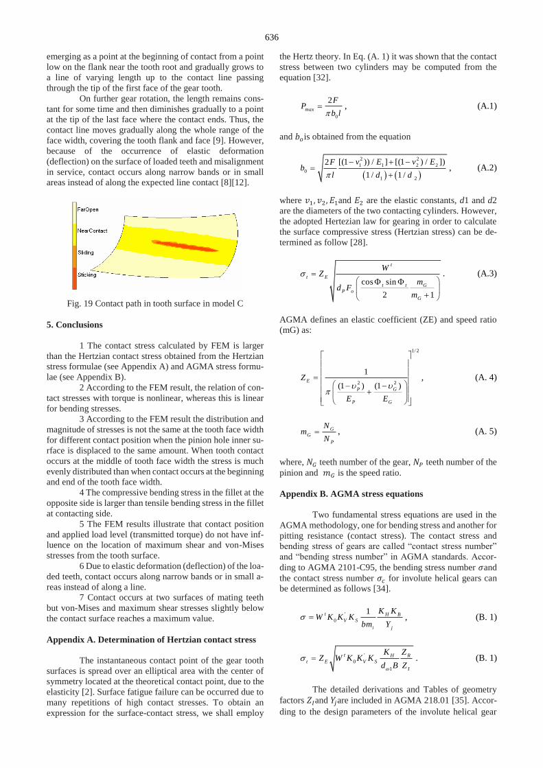
636
emerging as a point at the beginning of contact from a point
low on the flank near the tooth root and gradually grows to
a line of varying length up to the contact line passing
through the tip of the first face of the gear tooth.
On further gear rotation, the length remains cons-
tant for some time and then diminishes gradually to a point
at the tip of the last face where the contact ends. Thus, the
contact line moves gradually along the whole range of the
face width, covering the tooth flank and face [9]. However,
because of the occurrence of elastic deformation
(deflection) on the surface of loaded teeth and misalignment
in service, contact occurs along narrow bands or in small
areas instead of along the expected line contact [8][12].
Fig. 19 Contact path in tooth surface in model C
5. Conclusions
1 The contact stress calculated by FEM is larger
than the Hertzian contact stress obtained from the Hertzian
stress formulae (see Appendix A) and AGMA stress formu-
lae (see Appendix B).
2 According to the FEM result, the relation of con-
tact stresses with torque is nonlinear, whereas this is linear
for bending stresses.
3 According to the FEM result the distribution and
magnitude of stresses is not the same at the tooth face width
for different contact position when the pinion hole inner su-
rface is displaced to the same amount. When tooth contact
occurs at the middle of tooth face width the stress is much
evenly distributed than when contact occurs at the beginning
and end of the tooth face width.
4 The compressive bending stress in the fillet at the
opposite side is larger than tensile bending stress in the fillet
at contacting side.
5 The FEM results illustrate that contact position
and applied load level (transmitted torque) do not have inf-
luence on the location of maximum shear and von-Mises
stresses from the tooth surface.
6 Due to elastic deformation (deflection) of the loa-
ded teeth, contact occurs along narrow bands or in small a-
reas instead of along a line.
7 Contact occurs at two surfaces of mating teeth
but von-Mises and maximum shear stresses slightly below
the contact surface reaches a maximum value.
Appendix A. Determination of Hertzian contact stress
The instantaneous contact point of the gear tooth
surfaces is spread over an elliptical area with the center of
symmetry located at the theoretical contact point, due to the
elasticity [2]. Surface fatigue failure can be occurred due to
many repetitions of high contact stresses. To obtain an
expression for the surface-contact stress, we shall employ
the Hertz theory. In Eq. (A. 1) it was shown that the contact
stress between two cylinders may be computed from the
equation [32].
0
2max
FP
b l , (A.1)
and 𝑏𝑜is obtained from the equation
2 2
1 2
1 1 2 2
0
[(1 )) / ] [
1 /
(1 ) / ]
1 /
)2 v E v Eb
l d
F
d
, (A.2)
where 𝑣1, 𝑣2, 𝐸1and 𝐸2 are the elastic constants, d1 and d2
are the diameters of the two contacting cylinders. However,
the adopted Hertezian law for gearing in order to calculate
the surface compressive stress (Hertzian stress) can be de-
termined as follow [28].
cos sin
2 1
t
t E
P o
t t G
G
W
mZ
d Fm
. (A.3)
AGMA defines an elastic coefficient (ZE) and speed ratio
(mG) as:
1/ 2
22
1
(1 )(1 )E
GP
P G
Z
E E
, (A. 4)
G
G
P
Nm
N , (A. 5)
where, 𝑁𝐺 teeth number of the gear, 𝑁𝑃 teeth number of the
pinion and 𝑚𝐺 is the speed ratio.
Appendix B. AGMA stress equations
Two fundamental stress equations are used in the
AGMA methodology, one for bending stress and another for
pitting resistance (contact stress). The contact stress and
bending stress of gears are called “contact stress number”
and “bending stress number” in AGMA standards. Accor-
ding to AGMA 2101-C95, the bending stress number 𝜎and
the contact stress number 𝜎𝑐 for involute helical gears can
be determined as follows [34].
'
0
1t H B
V S
i j
K KW K K K
bm Y , (B. 1)
'
0
1
t H R
t E V S
I
K ZZ W K K K
d B Z
. (B. 1)
The detailed derivations and Tables of geometry
factors 𝑍𝐼and 𝑌𝑗are included in AGMA 218.01 [35]. Accor-
ding to the design parameters of the involute helical gear

637
pair listed in Table 1, the geometry factor 𝑍𝐼 is 0.104, and
the values of geometry factor𝑌𝑗 is 0.4186 for the gears.
As the FEM analysis was carried out statically and ideally,
the gear loading was considered uniformly, the dynamic and
overload factors was considered one.
References
1. Tsay, C. 1988. Helical gears with involute shaped teeth:
geometry, computer simulation, tooth contact analysis,
and stress analysis, ASME J. Mech. Transmissions Au-
tomation 482. 2. .Chen, Y.C.; Tasy, C.B. 2002. Stress analysis of a
helical gear set with localized bearing contact, Finite
Element Anal. Des. 38(8): 707-723.
https://doi.org/10.1016/S0168-874X(01)00100-7.
3. Litvin, F. 1994. Gear Geometry and Applied Theory.
NJ: Prentice-Hall.
4. Litvin, F.L.; Kim, D. H. 1997. Computerized design,
generation and simulation of modified involute spur
gears with localized bearing contact and reduced level of
transmission errors, ASME. J. Mech. Des. 119(1): 96-
100.
https://doi.org/10.1115/1.2828795.
5. Litvin, F.L.; Chen, N.X.; Lu, J.; Handschuh, R.F.
1995. Computerized design and generation of low-noise
helical gears with modified surface topology, ASME. J.
Mech. Des. 117: 254-161. https://doi.org/10.1115/1.2826131.
6. Litvin, F.L.; Lian, Q.; Kapelevich, A.L. 2000.
Asymmetric modified spur gear drives: reduction of
noise, localization of contact, simulation of meshing and
stress analysis, Comput. Method Appl. Mech. Eng. 188;
363-390.
https://doi.org/10.1016/S0045-7825(99)00161-9.
7. Zhang, Y.; Fang, Z. 1997. Analysis of transmission
errors under load of helical gears with modified tooth
gears, ASME. J. Mech. Des. 119: 120-126.
https://doi.org/10.1115/1.2828773.
8. Failure analysis and prevention, ASM handbook, vol.
11., Metals Park (OH):American Society for Metals,
1986.
9. Asi, O. 2006. Fatigue failure of a helical gear in a
gearbox. 13: 1116- 25. Eng Fail Anal 13: 1116-1125.
https://doi.org/10.1016/j.engfailanal.2005.07.020.
10. Fatigue and fracture, ASM handbook, vol 19, American
Society for Metals, 1996.
11. Arikan, M.A.S.; Tamar, M. 1992. Tooth contact and
3-D stress analysis of involute helical gears. ASME,
International Power Transmission and Gearing
Conference 43(2): 461-468.
12. Roa, C.R.M.; Muthuveerappan, G. 1993. Finite
element modeling and stress analysis of helical gear
teeth. Comput. Struct. 49(6): 1095-1106.
https://doi.org/10.1016/0045-7949(93)90020-E.
13. Hedlund, J.; Lehtovaara, A. 2006. Modeling of helical
gear contact with tooth deflection, Tribology
International 40: 613-619.
https://doi.org/10.1016/j.triboint.2005.11.004.
14. Ding, Y.; Rieger, N.F. 2003. Spalling formation mecha-
nism for gears. Wear 254(12): 1307-1317.
https://doi.org/10.1016/S0043-1648(03)00126-1.
15. [Online]. Available from:
http:/www.elecon.com/gearworld/dat-gw-failure.html.
16. Flodin, A. 2000. Simulation of mild wear in helical
gears, Wear 241: 123-128.
https://doi.org/10.1016/S0043-1648(00)00384-7.
17. Coy, J.J.; Chao, CH.C. 1982. A method of selecting
grid size to account for Hertz deformation in finite ele-
ment analysis of spur gears, J. Mech. Des. 104: 759-766,
https://doi.org/10.1115/1.3256429.
18. Du, S.; Randall, R. B.; Kelly, D. W. 1998. Modeling
of spur gear mesh stiffness and static transmission error,
Proc Inst Mech Eng part C 212: 287-297.
19. Arafa, M.H.; Megahed, M.M. 1999. Evaluation of spur
gear mesh compliance using the finite element method,
Proc. Inst. Mech. Eng. part C 213: 569-579.
https://doi.org/10.1243/0954406991522509.
20. Vedmar, L. 1981. On the design of external involute
helical gears, Transactions of Machine Elements
Division, Doctoral dissertation, Lund Technical
University, Lund, Sweden, 100 p,.
21. Pimsarn, M.; Kazerounian, K. 2002. Efficient
evaluation of spur gear tooth mesh load using pseudo-
interference stiffness estimation method., Mech. Mach.
Theory 37:. 769-786.
https://doi.org/10.1016/S0094-114X(02)00022-8.
22. Kawalec, A.; Wiktor, J.; Ceglarek, D. 2006.
Comparative Analysis of Tooth-Root Strength Using
ISO and AGMA Standards in Spur and Helical Gears
With FEM-based Verification, Journal of Mechanical
Design 128: 1141-1158.
https://doi.org/10.1115/1.2214735.
23. Qin, W.J.; Guan, C.Y. 2014. An investigation of
contact stresses and crack initiation in spur gears
basedon finite element dynamics analysis. Int. J. of
Mech. Sci. 83: 96-103.
https://doi.org/10.1016/j.ijmecsci.2014.03.035.
24. Barbieri, M.; Zippo, A.; Pelli-cano, F. 2014. Adaptive
grid-size finite element modeling of heli-cal gear pairs,
Mech. Mach. Theory 82: 17-32.
https://doi.org/10.1016/j.mechmachtheory.2014.07.009.
25. Santosh S. Patil; Saravanan, Karuppanan; Ivana,
Atanasovska; Azmi, Abdul, Wahab. 2014. Contact
stress analysis of helical gear pairs, including frictional
coefficients, Int. J. of Mech. Sci. 85: 205-211.
https://doi.org/10.1016/j.ijmecsci.2014.05.013.
26. Prabhu Sekar R.; Muthuveerappan, G. 2014. Load
sharing based maximum fillet stress analysis of
asymmetric helical gears designed through direct design
A parametric study, Mech. Mach. Theory 80: 84-102.
https://doi.org/10.1016/j.mechmachtheory.2014.04.021
27. Sell, D.J. 1992. Finite Element Modeling Spur and
Helical Gears in Contact, SAE 922440: 697-703,
https://doi.org/10.4271/922440.
28. Swanson Analysis Systems Inc. ANSYS, Release 12.
29. Mao, K. 2007. Gear tooth contact analysis and its
application in the reduction of fatigue wear, Wear 262:
1281-1288.
https://doi.org/10.1016/j.wear.2006.06.019.
30. Aziz, S.; Chassapis, C. 2002. Knowledge-based
Geometry Generation for Spur and Helical Gears,
Concurrent Engineering 10(3): 251-261.
https://doi.org/10.1177/106329302761689160.
31. Fernandes, P.J.L 1996. Tooth bending fatigue in gears,
Eng Fail Anal 3: 219-225.
https://doi.org/10.1016/1350-6307(96)00008-8.

638
32. Shigley, J.E.; Mischke, C.R. 2001. Mechanical
engineering design, McGraw-Hill,Sixth edition: 145-
919.
33. Fajdiga, G.; Glode, S.; Kramar, J. 2007. Pitting
formation due to surface and subsurface initiated fatigue
crack growth in contacting mechanical elements, Wear
262: 1217-1224.
https://doi.org/10.1016/j.wear.2006.11.016.
34. American Gear Manufacturers Association, AGMA
2101-C95, Fundamental rating factors and calculation
methods for involute spur and helical gear teeth, U.S.A,
1994.
35. American Gear Manufacturers Association, AGMA
218.01., Fundamental rating factors and calculation
methods for involute spur and helical gears, U,S,A,
1982.
M. Gh. Khosroshahi, A. M. Fattahi
THREE DIMENSIONAL STRESS ANALYSIS OF A
HELICAL GEAR DRIVE WITH FINITE ELEMENT
METHOD
S u m m a r y
Helical gears are widely used as power transmit-
ting gears between parallel or crossed shafts in gearbox or
other parts of machine, since not only can they carry large
load but also the noise level experienced during the opera-
tion is low. The application of parallel axis helical gears is
well established in gear industry. So stress analysis of invo-
lute-helical gears is very beneficial and has specific impor-
tance. However, due to their shape complexity using analy-
tical method to solve and gain stress distributions at engaged
teeth is very difficult task. To facilitate the convergency di-
fferent types of elements has been used for the contacting
surfaces and the rest of the model, respectively. In this pa-
per, the distribution of contact stresses, bending stresses and
torque transmission in the pinion for a given tangential
displacement (rotation) of the pinion hole surface was in-
vestigated using FEM and the obtained stresses are then
compared with Hertz theory and AGMA standard.
Keywords: helical gear; FEM; bending stress; contact
stress; Hertz theory; AGMA standard.
Received May 01, 2016
Accepted October 13, 2017


![14 Dimension Sheets: Upright Gear Units Mounting Position … · Catalog – X.. Series Helical and Bevel-Helical Gear Units 357 14 X.F.. helical gear units [mm] Dimension Sheets:](https://img.pdfslide.net/doc/110x75/5b918f7f09d3f26a278bf43b/14-dimension-sheets-upright-gear-units-mounting-position-catalog-x-series.jpg)