Embed Size (px)
Citation preview
1
Three-dimensional Topology of Hairpin Packet Structure in Turbulent Boundary Layer
by
K.C. Kim(1) and S.H. Kwon
School of Mechanical Engineering
Pusan National University
Jangjeon-dong, Geumjeong-gu, Busan 609-735, Korea (1)E-Mail: [email protected]
ABSTRACT
An experimental investigation has been made regarding a three-dimensional topology of a zero-pressure gradient turbulent boundary layer. In this study, a novel polarization separation technique has been applied to the PIV measurements. A mutually-perpendicular measurement planes has been employed in x-y and x-z planes, respectively. Synchronization between a stereoscopic PIV with another plane PIV system has enabled the extraction of a true three-dimensional flow structure. Polarization rotation via half wave plate and subsequent particle image separation using polarizer minimized the spurious particle images. The PIV results clearly demonstrate the presence of hairpin-like coherent vortical structure and coincidence between the near-wall quasi-streamwise vortex pair and the legs of the hairpin vortex. In addition, a hairpin packet structure, in which hairpin vortices occurs in group in confined region, is exemplified.
1. INTRODUCTION
Turbulent boundary layer flow has long been a subject of fundamental fluid dynamic research. The presence of large-scale coherent structure is undoubtedly the most relevant agent for increased turbulent momentum and heat transfer from the wall. Hence, the understanding of the coherent structures in turbulent boundary layer flow is of prime importance in such flow control viewpoint as the drag reduction. Since the first suggestion by Theodorsen (1952) and subsequent visualization study by Head and Bandyopadhyay (1981), a hairpin or horseshoe vortex has been considered a central feature of coherent structures. This model was then substantiated by the hydrogen bubble visualization by Smith (1984). Conceptual models, which explained the generation mechanism of single hairpin vortex, were proposed by Perry and Chong (1982) and Perry et al. (1986). Developments in the direct numerical simulation of turbulent boundary layer flow enabled a more systematic investigation of coherent structures and their dynamic behavior. The most notable example is Robinson (1991), where generalization of the fairly simple model with symmetrical hairpin vortices was made to include asymmetric hairpin vortices with unequal leg lengths. In addition, the legs of hairpin vortices were shown to be stretched by the mean shear to form a counter-rotating, quasi-streamwise vortex pair, which was connected to 45° inclined necks. The interaction between the quasi-streamwise vortex pair and the low-speed streak was then analyzed to demonstrate that the ejection of low-speed fluid is induced by the pumping action of the vortex pair. Thus, the second quadrant ejection event as well as the fourth quadrant sweep event, which were originally observed experimentally by Blackwelder and Kaplan (1976), was attributed to the action of the coherent hairpin vortical structures. Contrary to the earlier model of individual hairpins, Zhou et al. (1999) found a packet structure in which a group of hairpins occurs in association of low-speed streaks through a stochastic estimation of DNS data. They also proposed a model for the successive regeneration mechanism of the new vortices from the primary hairpin vortex. The organization of vortex packet, pertinent also to the outer region of boundary layer, was then demonstrated by Adrian et al. (2000) using a high resolution PIV (Particle Image Velocimetry). Owing to the rapid improvement of particle image velocimetry, spatial structure of turbulent boundary layer can be investigated experimentally with an unprecedented spatial resolution. A literature survey, however, reveals that a true three-dimensional topology of hairpin vortex packet has not been identified in an experimental basis. Most existing PIV observations exemplify a cross-sectional structure, namely, in x-y plane. Although the Holographic PIV can give a three-
2
dimensional distribution of velocity vectors, the application of this technique has scarcely been made so far. This is mainly due to the complexity of optical setup and difficulties in measurement. Recently, a dual-plane stereoscopic PIV system was proposed by Saga (2002), utilizing different polarizing direction between each measurement plane, where the dual measurement planes were parallel to each other. In this study, an extension of this technique to mutually perpendicular plane setup is made toward the clarification of the coincidence of relevant flow structures observed in three-dimensionally arranged instantaneous velocity vector fields. Conditional sampling of hairpin signature is also performed to extract the coherent structures. The present PIV study aims to provide a three-dimensional topology of hairpin vortex packets .
2. EXPERIMENTAL METHOD and PROCEDURES
2.1 Wind tunnel and flow condition
A zero-pressure gradient turbulent boundary layer was formed inside a test section of a suction type subsonic open circuit wind tunnel. Flow is taken in through the honeycomb and subsequent three steel wire meshes. Downstream of the wire meshes, a smooth contraction fairing with the area ratio of 5:1 was installed. The dimension of rectangular entrance duct, which connected the contraction with the test section, was 1,800mm in length, 800mm in width and 300mm in height.
The test section consisted of glass plate to facilitate a clear particle image acquisition with the CCD cameras. The test section was a rectangular cross sectional duct, whose length and width were 2,400mm and 800mm, respectively. The inclination of top wall of the test section was adjustable to generate a zero-pressure gradient boundary layer at the bottom wall. In order to promote uniform laminar-turbulent transition in the spanwise direction, a trip wire with the diameter of 5mm was attached at 50mm downstream of the test section entrance. Downstream of the trip wire, a sandpaper strip (roughness 60) was installed up to the streamwise distance of 600mm. Suction flow through the wind tunnel was driven by the fan installed at a settling chamber downstream of the test section. The velocity in the test section was controlled by means of the inverter. The freestream turbulence intensity was measured below 0.5% at speeds 1 to 5m/s.
Case Reθ=934 U∞ 2.87 m/s uτ 0.1361 m/s δ 58 mm θ 5.08 mm H 1.226
Reδ 10,671
Table.1. Flow Parameters
The Reynolds numbers, based on the momentum thickness θ, of the turbulent boundary layer was set to Reθ=934. The corresponding freestream velocities was 2.87m/s. Table 1 summarizes the flow conditions in the present study. From the shape factors of 1.226, the boundary layer is considered to be fully turbulent.
2.2 PIV and polarizing optical setup
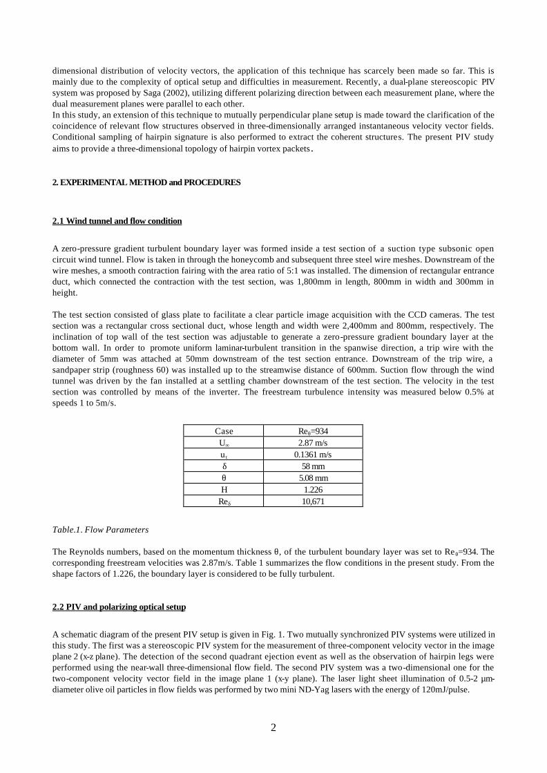
A schematic diagram of the present PIV setup is given in Fig. 1. Two mutually synchronized PIV systems were utilized in this study. The first was a stereoscopic PIV system for the measurement of three-component velocity vector in the image plane 2 (x-z plane). The detection of the second quadrant ejection event as well as the observation of hairpin legs were performed using the near-wall three-dimensional flow field. The second PIV system was a two-dimensional one for the two-component velocity vector field in the image plane 1 (x-y plane). The laser light sheet illumination of 0.5-2 µm-diameter olive oil particles in flow fields was performed by two mini ND-Yag lasers with the energy of 120mJ/pulse.
3
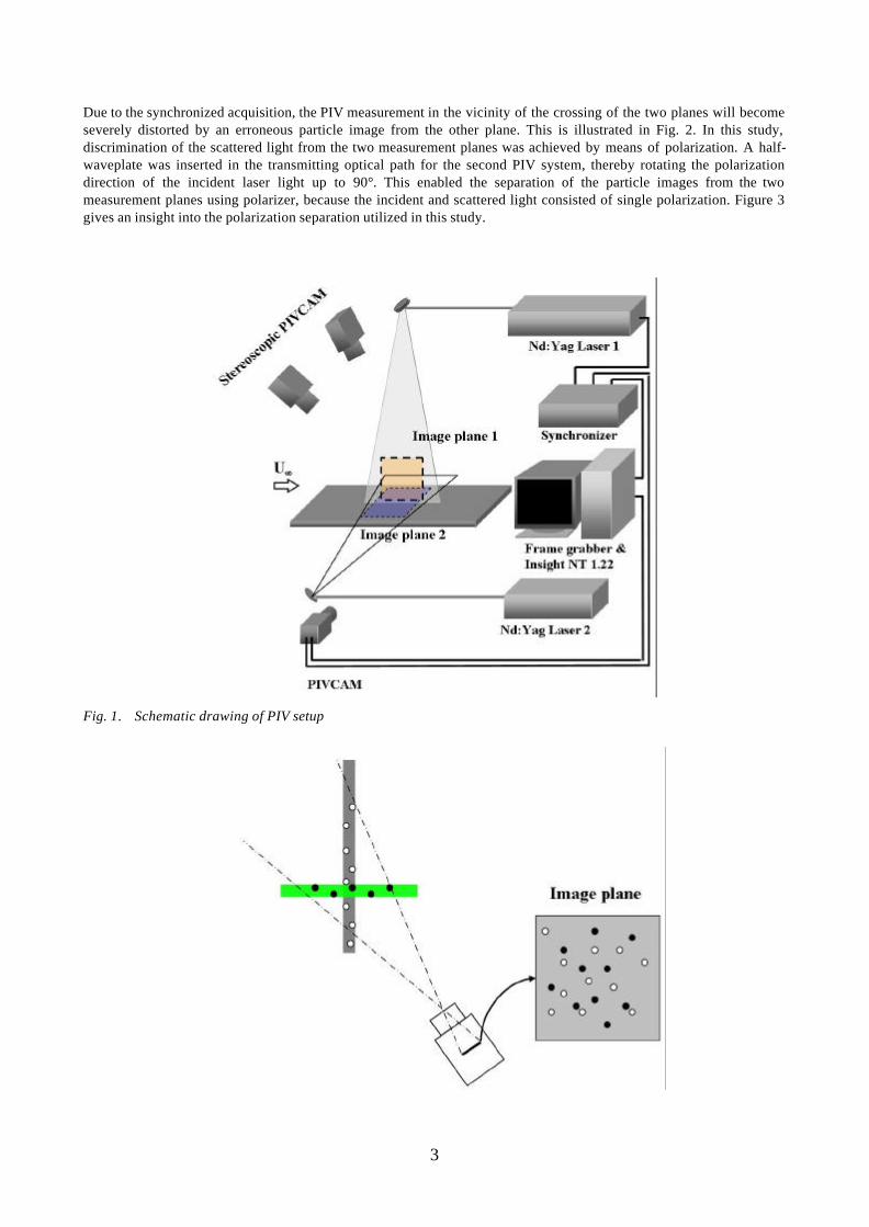
Due to the synchronized acquisition, the PIV measurement in the vicinity of the crossing of the two planes will become severely distorted by an erroneous particle image from the other plane. This is illustrated in Fig. 2. In this study, discrimination of the scattered light from the two measurement planes was achieved by means of polarization. A half-waveplate was inserted in the transmitting optical path for the second PIV system, thereby rotating the polarization direction of the incident laser light up to 90°. This enabled the separation of the particle images from the two measurement planes using polarizer, because the incident and scattered light consisted of single polarization. Figure 3 gives an insight into the polarization separation utilized in this study.
Fig. 1. Schematic drawing of PIV setup
4
Fig. 2 Erroneous particle image in crossing of two light sheets
Fig. 3 Filtering of polarized lights
The particle displacement was calculated using the cross-correlation algorithm. The interrogation window was 48×48 pixels in size and overlapped 50%. The removal of error vector was achieved via a median filter. The velocity vectors were then ensemble averaged to obtain the time-mean velocity vector field. The numbers of ensemble average were 1,000 and 600 for the x-y plane and x-z plane, respectively. All of the above-mentioned processes, including the calculation of three-dimensional particle displacement, were performed using an in-house stereoscopic PIV software (PIV-ACE).
3. RESULTS AND DISCUSSION
3.1 Validity of polarization separation technique
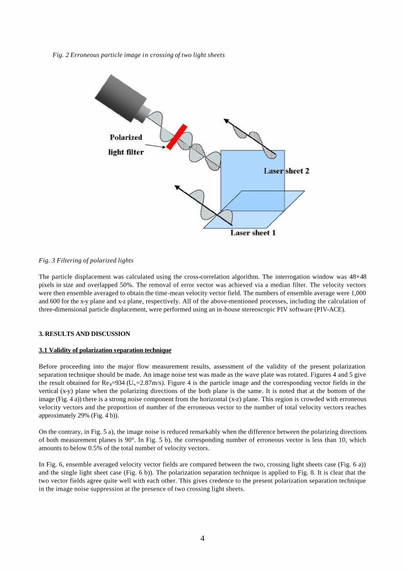
Before proceeding into the major flow measurement results, assessment of the validity of the present polarization separation technique should be made. An image noise test was made as the wave plate was rotated. Figures 4 and 5 give the result obtained for Reθ=934 (U∞=2.87m/s). Figure 4 is the particle image and the corresponding vector fields in the vertical (x-y) plane when the polarizing directions of the both plane is the same. It is noted that at the bottom of the image (Fig. 4 a)) there is a strong noise component from the horizontal (x-z) plane. This region is crowded with erroneous velocity vectors and the proportion of number of the erroneous vector to the number of total velocity vectors reaches approximately 29% (Fig. 4 b)).
On the contrary, in Fig. 5 a), the image noise is reduced remarkably when the difference between the polarizing directions of both measurement planes is 90°. In Fig. 5 b), the corresponding number of erroneous vector is less than 10, which amounts to below 0.5% of the total number of velocity vectors.
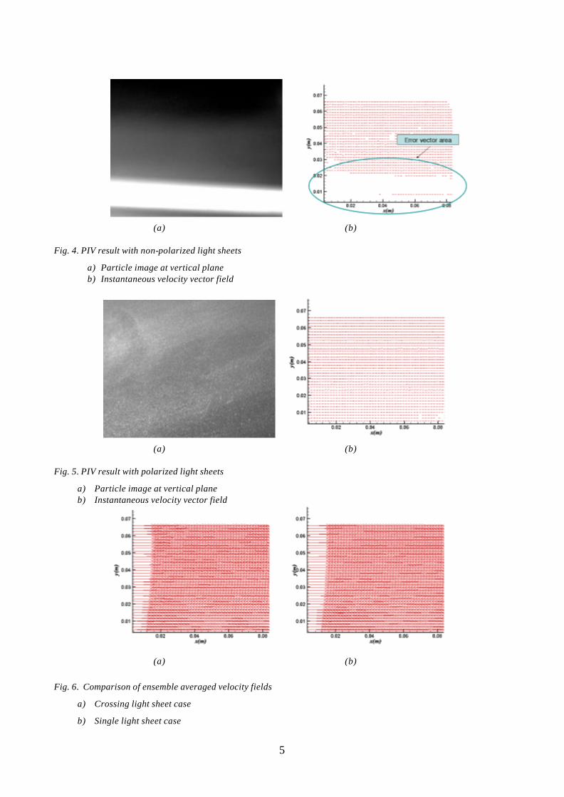
In Fig. 6, ensemble averaged velocity vector fields are compared between the two, crossing light sheets case (Fig. 6 a)) and the single light sheet case (Fig. 6 b)). The polarization separation technique is applied to Fig. 8. It is clear that the two vector fields agree quite well with each other. This gives credence to the present polarization separation technique in the image noise suppression at the presence of two crossing light sheets.
5
(a) (b)
Fig. 4. PIV result with non-polarized light sheets
a) Particle image at vertical plane b) Instantaneous velocity vector field
(a) (b) Fig. 5. PIV result with polarized light sheets
a) Particle image at vertical plane b) Instantaneous velocity vector field
(a) (b)
Fig. 6. Comparison of ensemble averaged velocity fields
a) Crossing light sheet case
b) Single light sheet case
6
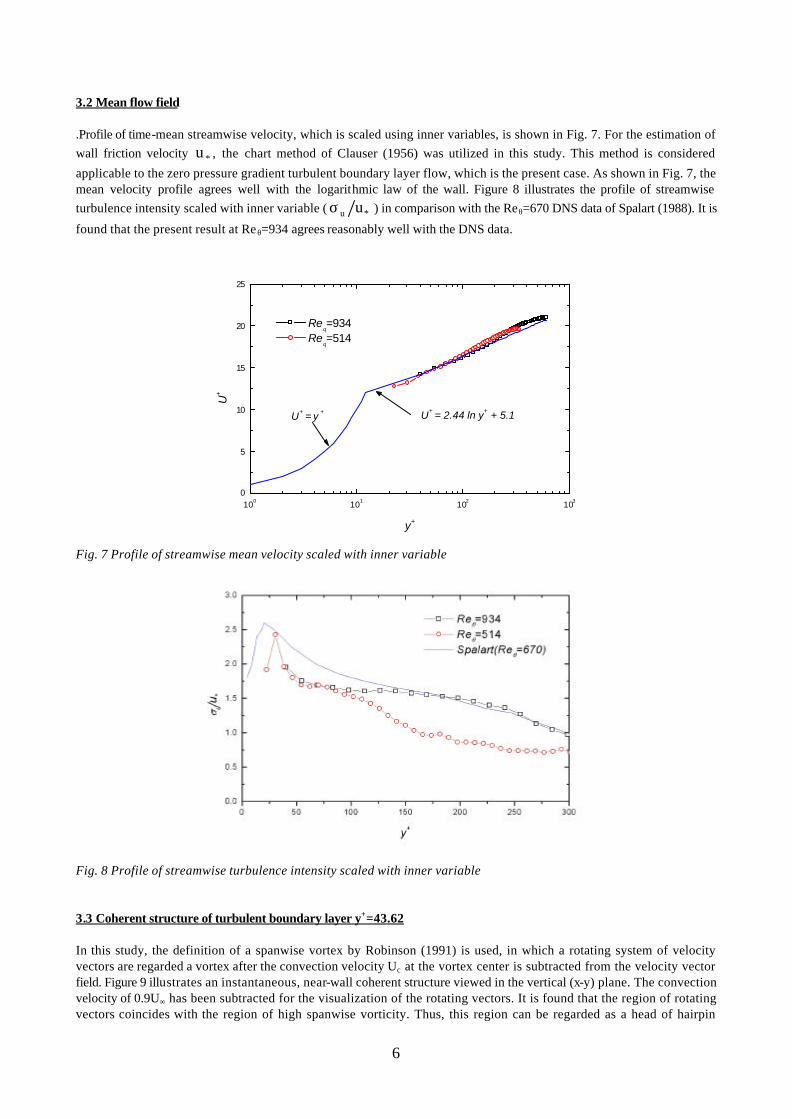
3.2 Mean flow field
.Profile of time-mean streamwise velocity, which is scaled using inner variables, is shown in Fig. 7. For the estimation of wall friction velocity *u , the chart method of Clauser (1956) was utilized in this study. This method is considered
applicable to the zero pressure gradient turbulent boundary layer flow, which is the present case. As shown in Fig. 7, the mean velocity profile agrees well with the logarithmic law of the wall. Figure 8 illustrates the profile of streamwise turbulence intensity scaled with inner variable ( *u uσ ) in comparison with the Reθ=670 DNS data of Spalart (1988). It is
found that the present result at Reθ=934 agrees reasonably well with the DNS data.
100 101 102 1030
5
10
15
20
25
U+ = 2.44 ln y+ + 5.1U+ = y +
Reθ=934
Reθ=514
U+
y+
Fig. 7 Profile of streamwise mean velocity scaled with inner variable
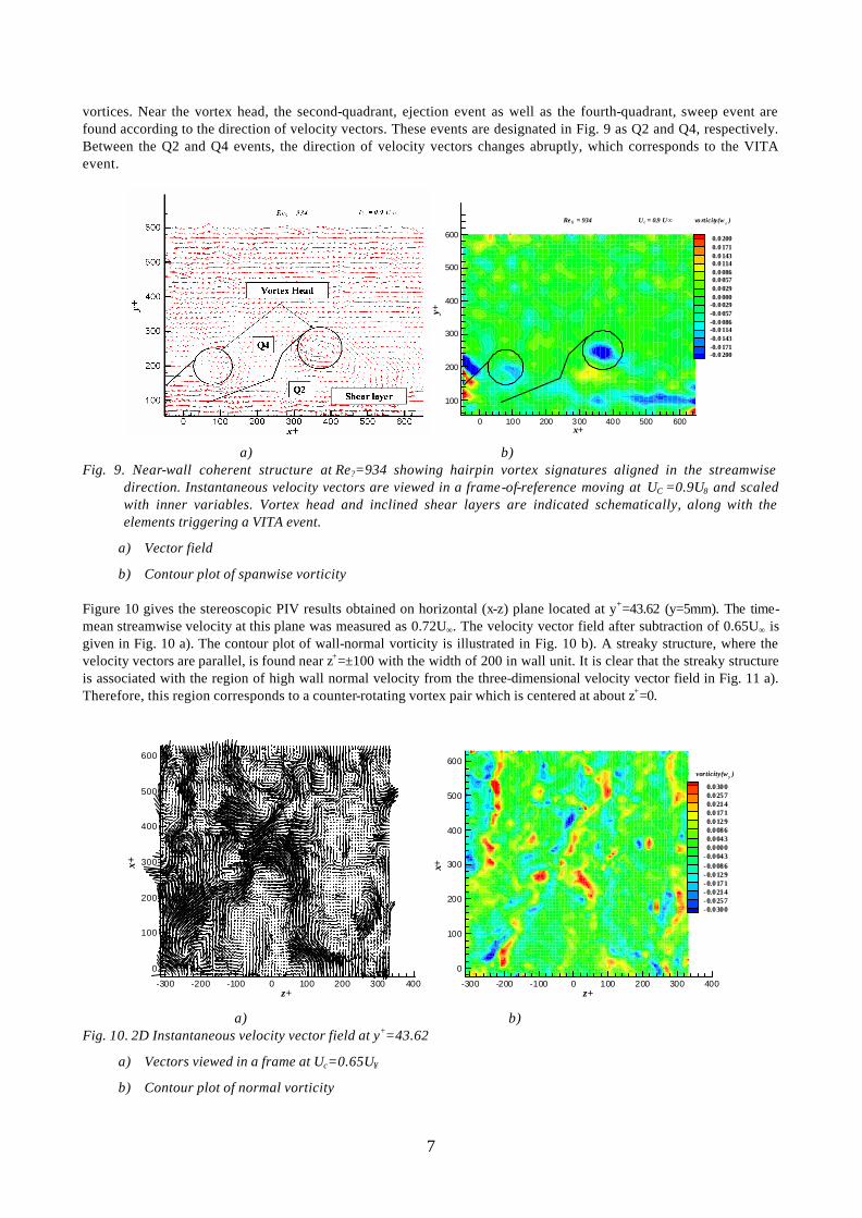
Fig. 8 Profile of streamwise turbulence intensity scaled with inner variable
3.3 Coherent structure of turbulent boundary layer y+=43.62 In this study, the definition of a spanwise vortex by Robinson (1991) is used, in which a rotating system of velocity vectors are regarded a vortex after the convection velocity Uc at the vortex center is subtracted from the velocity vector field. Figure 9 illustrates an instantaneous, near-wall coherent structure viewed in the vertical (x-y) plane. The convection velocity of 0.9U∞ has been subtracted for the visualization of the rotating vectors. It is found that the region of rotating vectors coincides with the region of high spanwise vorticity. Thus, this region can be regarded as a head of hairpin
7
vortices. Near the vortex head, the second-quadrant, ejection event as well as the fourth-quadrant, sweep event are found according to the direction of velocity vectors. These events are designated in Fig. 9 as Q2 and Q4, respectively. Between the Q2 and Q4 events, the direction of velocity vectors changes abruptly, which corresponds to the VITA event.
x+y+
0 100 200 300 400 500 600
100
200
300
400
500
600 0.0 2000.0 1710.0 1430.0 1140.0 0860.0 0570.0 0290.0 000
-0.0 029-0.0 057-0.0 086-0.0 114-0.0 143-0.0 171-0.0 200
U c = 0.9 U∞Re = 934θ vo rticity(w z )
a) b)
Fig. 9. Near-wall coherent structure at Re?=934 showing hairpin vortex signatures aligned in the streamwise direction. Instantaneous velocity vectors are viewed in a frame-of-reference moving at UC =0.9U8 and scaled with inner variables. Vortex head and inclined shear layers are indicated schematically, along with the elements triggering a VITA event.
a) Vector field
b) Contour plot of spanwise vorticity
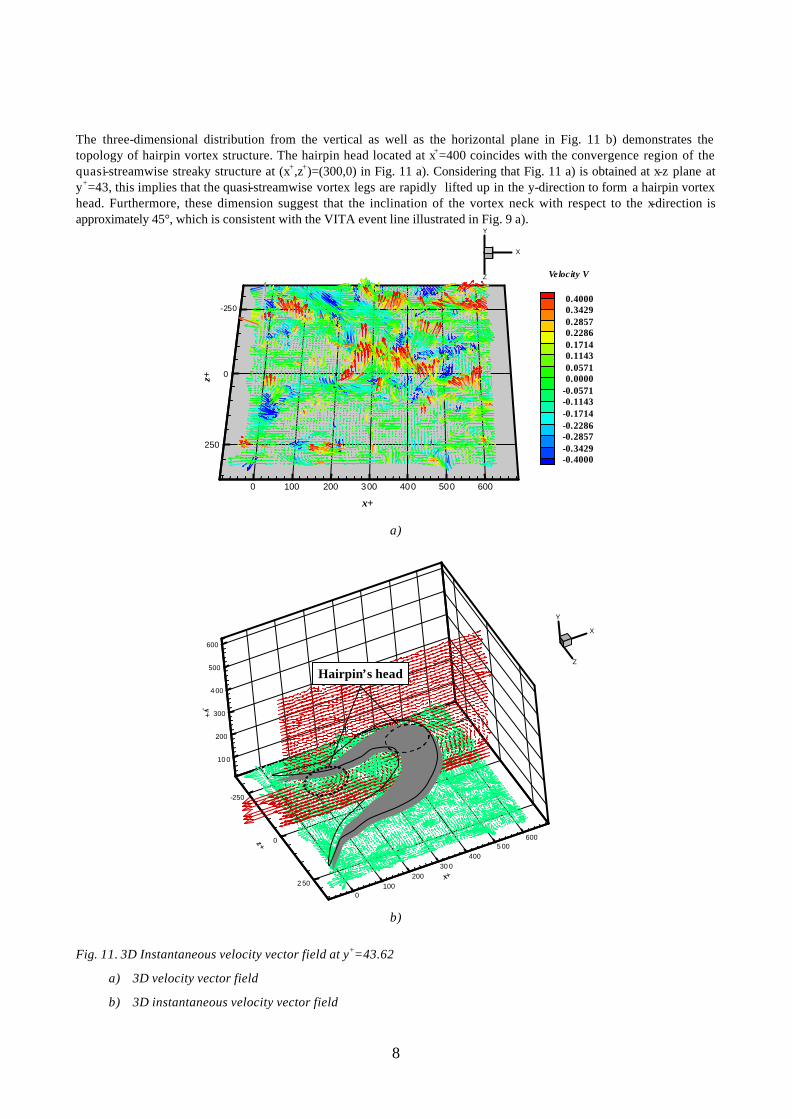
Figure 10 gives the stereoscopic PIV results obtained on horizontal (x-z) plane located at y+=43.62 (y=5mm). The time-mean streamwise velocity at this plane was measured as 0.72U∞. The velocity vector field after subtraction of 0.65U∞ is given in Fig. 10 a). The contour plot of wall-normal vorticity is illustrated in Fig. 10 b). A streaky structure, where the velocity vectors are parallel, is found near z+=±100 with the width of 200 in wall unit. It is clear that the streaky structure is associated with the region of high wall normal velocity from the three-dimensional velocity vector field in Fig. 11 a). Therefore, this region corresponds to a counter-rotating vortex pair which is centered at about z+=0.
z+
x+
-300 -200 -100 0 100 200 300 400
0
100
200
300
400
500
600
z+
x+
-300 -200 -100 0 100 200 300 400
0
100
200
300
400
500
600
0.03000.02570.02140.01710.01290.00860.00430.0000
-0.0043-0.0086-0.0129-0.0171-0.0214-0.0257-0.0300
vorticity(w y )
a) b) Fig. 10. 2D Instantaneous velocity vector field at y+=43.62
a) Vectors viewed in a frame at Uc=0.65U∞
b) Contour plot of normal vorticity
8
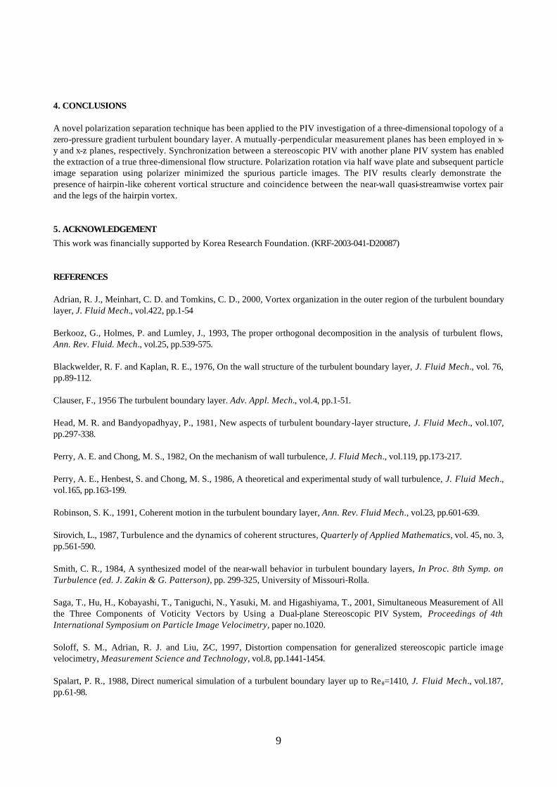
The three-dimensional distribution from the vertical as well as the horizontal plane in Fig. 11 b) demonstrates the topology of hairpin vortex structure. The hairpin head located at x+=400 coincides with the convergence region of the quasi-streamwise streaky structure at (x+,z+)=(300,0) in Fig. 11 a). Considering that Fig. 11 a) is obtained at x-z plane at y+=43, this implies that the quasi-streamwise vortex legs are rapidly lifted up in the y-direction to form a hairpin vortex head. Furthermore, these dimension suggest that the inclination of the vortex neck with respect to the x-direction is approximately 45°, which is consistent with the VITA event line illustrated in Fig. 9 a).
a)
0100
20030 0
4005 00
600
x+
-250
0
2 50
z+
10 0
200
300
4 00
500
600
y+
X
Y
Z
Hairpin’s head
0100
20030 0
4005 00
600
x+
-250
0
2 50
z+
10 0
200
300
4 00
500
600
y+
X
Y
Z
Hairpin’s head
b)
Fig. 11. 3D Instantaneous velocity vector field at y+=43.62
a) 3D velocity vector field
b) 3D instantaneous velocity vector field
0 100 200 300 400 500 600
x+
-250
0
250
z+
X
Y
Z
0.40000.34290.28570.22860.17140.11430.05710.0000
-0.0571-0.1143-0.1714-0.2286-0.2857-0.3429-0.4000
Velocity V
9
4. CONCLUSIONS
A novel polarization separation technique has been applied to the PIV investigation of a three-dimensional topology of a zero-pressure gradient turbulent boundary layer. A mutually-perpendicular measurement planes has been employed in x-y and x-z planes, respectively. Synchronization between a stereoscopic PIV with another plane PIV system has enabled the extraction of a true three-dimensional flow structure. Polarization rotation via half wave plate and subsequent particle image separation using polarizer minimized the spurious particle images. The PIV results clearly demonstrate the presence of hairpin-like coherent vortical structure and coincidence between the near-wall quasi-streamwise vortex pair and the legs of the hairpin vortex.
5. ACKNOWLEDGEMENT
This work was financially supported by Korea Research Foundation. (KRF-2003-041-D20087)
REFERENCES Adrian, R. J., Meinhart, C. D. and Tomkins, C. D., 2000, Vortex organization in the outer region of the turbulent boundary layer, J. Fluid Mech., vol.422, pp.1-54 Berkooz, G., Holmes, P. and Lumley, J., 1993, The proper orthogonal decomposition in the analysis of turbulent flows, Ann. Rev. Fluid. Mech., vol.25, pp.539-575. Blackwelder, R. F. and Kaplan, R. E., 1976, On the wall structure of the turbulent boundary layer, J. Fluid Mech., vol. 76, pp.89-112. Clauser, F., 1956 The turbulent boundary layer. Adv. Appl. Mech., vol.4, pp.1-51. Head, M. R. and Bandyopadhyay, P., 1981, New aspects of turbulent boundary-layer structure, J. Fluid Mech., vol.107, pp.297-338. Perry, A. E. and Chong, M. S., 1982, On the mechanism of wall turbulence, J. Fluid Mech., vol.119, pp.173-217. Perry, A. E., Henbest, S. and Chong, M. S., 1986, A theoretical and experimental study of wall turbulence, J. Fluid Mech., vol.165, pp.163-199. Robinson, S. K., 1991, Coherent motion in the turbulent boundary layer, Ann. Rev. Fluid Mech., vol.23, pp.601-639. Sirovich, L., 1987, Turbulence and the dynamics of coherent structures, Quarterly of Applied Mathematics, vol. 45, no. 3, pp.561-590. Smith, C. R., 1984, A synthesized model of the near-wall behavior in turbulent boundary layers, In Proc. 8th Symp. on Turbulence (ed. J. Zakin & G. Patterson), pp. 299-325, University of Missouri-Rolla. Saga, T., Hu, H., Kobayashi, T., Taniguchi, N., Yasuki, M. and Higashiyama, T., 2001, Simultaneous Measurement of All the Three Components of Voticity Vectors by Using a Dual-plane Stereoscopic PIV System, Proceedings of 4th International Symposium on Particle Image Velocimetry, paper no.1020. Soloff, S. M., Adrian, R. J. and Liu, Z-C, 1997, Distortion compensation for generalized stereoscopic particle image velocimetry, Measurement Science and Technology, vol.8, pp.1441-1454. Spalart, P. R., 1988, Direct numerical simulation of a turbulent boundary layer up to Reθ=1410, J. Fluid Mech., vol.187, pp.61-98.
10
Theodorsen, T., 1952, Mechanism of turbulence, Proceedings of the Second Midwestern Conference of Fluid Mechanics, pp.1-19, Ohio State University, Columbus, Ohio. Zhou, J., Adrian, R. J., Balachandar, S. and Kendall, T. M., 1999, Mechanisms for generating coherent packets of hairpin vortices in channel flow, J. Fluid Mech., vol.387, pp.353-396.