Embed Size (px)
Citation preview
Har Hotzvim Industrial Park, 14 Hartom St., P.O.B. 45029, Jerusalem 91450, Israel
Tel: 972-2-588-8222 Fax: 972-2-582-8875 Email: [email protected] Website: www.gamatronic.com
TTHHRREEEE--PPHHAASSEE TTRRAANNSSFFOORRMMEERRSS
Release 1.1, January 2012
Gamatronic Electronic Industries Ltd.
ii Isolation Transformers
Gamatronic Electronic Industries Ltd. Har Hotzvim Industrial Park 14 Hartom St., PO Box 45029, Jerusalem 91450 Israel Tel: +972-2-588-8222 Fax: +972-2-582-8875 Email: [email protected] Website: www.gamatronic.com
The equipment described in this document is not intended to be used in connection with any application requiring fail-safe performance, unless the application design includes appropriate redundancy. This exclusion includes, but is not limited to, the direct operation of any life support system or any other system whose failure could lead to serious injury, death, environmental damage or mass destruction.
Ó Copyright 2012 by Gamatronic Electronic Industries Ltd. All rights reserved worldwide. The information contained in this document is proprietary and is subject to all relevant copyright, patent and other laws protecting intellectual property, as well as any specific agreement protecting Gamatronic Electronic Industries Ltd. rights in the aforesaid information. Neither this document nor the information contained herein may be published, reproduced or disclosed to third parties, in whole or in part, without the express, prior, written permission of Gamatronic Electronic Industries Ltd. In addition, any use of this document or the information contained herein for any purposes other than those for which it was disclosed is strictly forbidden. Gamatronic Electronic Industries Ltd. reserves the right, without prior notice or liability, to make changes in equipment design or specifications. Information supplied by Gamatronic Electronic Industries Ltd. is believed to be accurate and reliable. However, no responsibility is assumed by Gamatronic Electronic Industries Ltd. for the use thereof nor for the rights of third parties which may be affected in any way by the use thereof. Any representation(s) in this document concerning performance of Gamatronic Electronic Industries Ltd. product(s) are for informational purposes only and are not warranties of future performance, either express or implied. Gamatronic Electronic Industries Ltd. standard limited warranty, stated in its sales contract or order confirmation form, is the only warranty offered by Gamatronic Electronic Industries Ltd. in relation thereto. This document may contain flaws, omissions or typesetting errors; no warranty is granted nor liability assumed in relation thereto unless specifically undertaken in Gamatronic Electronic Industries Ltd. sales contract or order confirmation. Information contained herein is periodically updated and changes will be incorporated into subsequent editions. If you have encountered an error, please notify Gamatronic Electronic Industries Ltd. All specifications are subject to change without prior notice.
Gamatronic Electronic Industries Ltd.
Isolation Transformers iii
TABLE OF CONTENTS 1. INTRODUCTION TO TRANSFORMERS ................................................................. 1
1.1 Galvanic isolation transformers ............................................................................. 2 1.2 Transformer standards .......................................................................................... 2 1.3 Three-phase transformers ..................................................................................... 3
1.3.1 ........ Delta and Wye connections ................................................................. 3
2. GAMATRONIC'S ISOLATION TRANSFORMERS ..................................................... 5 2.1 Features ................................................................................................................. 5 2.2 Two examples of typical isolation transformers ..................................................... 6 2.3 Installation instructions .......................................................................................... 8
3. TECHNICAL SPECIFICATIONS ........................................................................... 9
LIST OF FIGURES FIGURE 1: A SIMPLE TRANSFORMER ............................................................................................... 1 FIGURE 2: A 3-PHASE TRANSFORMER CORE ................................................................................... 3 FIGURE 3: THREE PRIMARY WINDINGS IN DELTA AND THREE SECONDARY WINDINGS IN WYE ............. 4 FIGURE 4: GENERALIZED TRANSFORMER SCHEMATIC, DELTA-WYE CONFIGURATION ......................... 6 FIGURE 5: GENERALIZED TRANSFORMER SCHEMATIC, WYE-WYE CONFIGURATION ........................... 7
LIST OF TABLES TABLE 1: GAMATRONIC'S TRANSFORMERS: GENERAL SPECIFICATIONS * ........................................... 9 TABLE 2: TECHNICAL SPECIFICATIONS FOR TRANSFORMERS OF VARIOUS SIZES * ............................11

Gamatronic Electronic Industries Ltd.
iv Isolation Transformers
This page left blank deliberately.

Gamatronic Electronic Industries Ltd.
Isolation Transformers
1
1. INTRODUCTION TO TRANSFORMERS A transformer is a device that transfers electrical energy from one circuit to another through inductively coupled conductors—the transformer's coils (windings). The transformer's coils are usually wound around a metal centerpiece – the core. Passing alternating current (ac) through the first or primary winding creates a varying magnetic flux in the transformer's core and thus a varying magnetic field through the secondary winding. This varying magnetic field induces an ac voltage in the secondary winding. This effect is called inductive coupling.
Figure 1 illustrates a simple, ideal transformer. Ac current passing through the primary coil creates a varying magnetic field. The primary and secondary coils are wrapped around a core of very high magnetic permeability, such as iron, so that most of the magnetic flux passes through both the primary and secondary coils. If a load is connected to the secondary winding, an electric current will flow in the secondary winding and electrical energy will be transferred from the primary circuit through the transformer to the load. In an ideal transformer, the induced voltage in the secondary winding (Vs) is in proportion to the primary voltage (Vp), and is given by the ratio of the number of turns in the secondary (Ns) to the number of turns in the primary (Np) as follows:
By using the appropriate ratio of turns, a transformer can increase an ac voltage by making Ns greater than Np, or decrease ac voltage by making Ns less than Np.
Figure 1: A simple transformer
Gamatronic Electronic Industries Ltd.
Isolation Transformers 2
1.1 Galvanic isolation transformers A galvanic isolation transformer is a transformer used to supply electrical power from an ac source to some equipment or device while isolating the powered device from the power source. In power electronics, this is usually done to supress electrical noise in sensitive devices, and to minimize or eliminate any dc component in the voltage supplied to the load device. Transformers are often required for medical devices, for safety purposes.
Suitably designed isolation transformers block interference caused by ground loops. Isolation transformers with electrostatic shields are used for power supplies for sensitive equipment such as computers or laboratory instruments.
Isolation transformers are usually built with special insulation between the primary and secondary windings, and is tested, specified, and marked to withstand a high voltage – typically in the 1000 to 5000 volt range – between windings, and between each winding and ground.
There are generally two types of isolation: one that relies on protective earth ground and one that relies on double or reinforced insulation. A transformer that relies on protective earth ground uses a basic isolation between the primary and the safety shield and shield to secondary. This shield has to be thick to be able to meet required tests in the safety standard. If the isolation fails, the electrical path goes directly to ground, providing safety.
A transformer that relies on double or reinforced insulation has no safety shield. Instead, the insulation used in the coil is much thicker. These transformers are designed so that all layers of the insulation can pass the thickness and high potential voltage tests required. If one insulation layer breaks, the next layer will be able to provide the required safety.
1.2 Transformer standards Various national and international safety agencies have published standards relevant to the design, construction and testing of transformers. A partial list of those standards follows.
Standards published by the International Electrotechnical Commission (IEC) include:
· IEC 60076 Power transformers
· IEC 60905 Loading guide for dry-type power transformerst
· IEC 61000 Electromagnetic compatibility (EMC)
· IEC 61558 Safety of transformers, reactors, power supply units Standards published by Underwriters Laboratories (UL):
· UL 5085 Standard for Low Voltage UL 5085
· UL 544 Medical and dental equipment Canadian Standards Association (CSA)
· C22.2 NO. 66.1-06 Low-voltage transformers
There exist a number of regional, national, and local deviations from the abovelisted standards. For example, in the U.S., the city of Los Angeles requires the use of tamperproof thermal protection and nonflammable materials in transformers, due the region's high seismic activity.
Gamatronic Electronic Industries Ltd.
Isolation Transformers
3
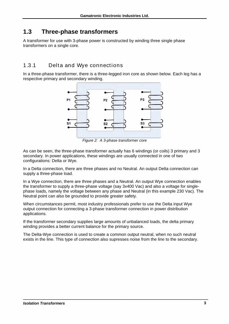
1.3 Three-phase transformers A transformer for use with 3-phase power is constructed by winding three single phase transformers on a single core.
1.3.1 Delta and Wye connections In a three-phase transformer, there is a three-legged iron core as shown below. Each leg has a respective primary and secondary winding.
Figure 2: A 3-phase transformer core
As can be seen, the three-phase transformer actually has 6 windings (or coils) 3 primary and 3 secondary. In power applications, these windings are usually connected in one of two configurations: Delta or Wye.
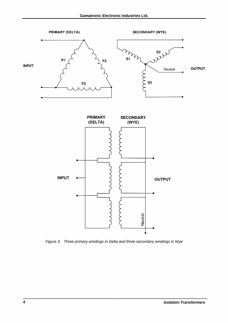
In a Delta connection, there are three phases and no Neutral. An output Delta connection can supply a three-phase load.
In a Wye connection, there are three phases and a Neutral. An output Wye connection enables the transformer to supply a three-phase voltage (say 3x400 Vac) and also a voltage for single-phase loads, namely the voltage between any phase and Neutral (in this example 230 Vac). The Neutral point can also be grounded to provide greater safety.
When circumstances permit, most industry professionals prefer to use the Delta input Wye output connection for connecting a 3-phase transformer connection in power distribution applications.
If the transformer secondary supplies large amounts of unbalanced loads, the delta primary winding provides a better current balance for the primary source.
The Delta-Wye connection is used to create a common output neutral, when no such neutral exists in the line. This type of connection also supresses noise from the line to the secondary.
Gamatronic Electronic Industries Ltd.
Isolation Transformers 4
Figure 3: Three primary windings in Delta and three secondary windings in Wye
Gamatronic Electronic Industries Ltd.
Isolation Transformers
5
2. GAMATRONIC'S ISOLATION TRANSFORMERS
2.1 Features · Gamatronic offers a wide selection of 3-phase isolation transformers. Standard models are
available in a range from 6 to 150 kVA, larger and smaller units are available on request.
· On customer request, Gamatronic can suppy transformers capable of accepting a range of input voltages and supplying any one of multiple output voltages: for example, 200 / 220 / 240 Vac. The voltage setting is modified by a switch or by a simple rewiring performed by the customer.
· Standard input and output voltages for the isolation transformers are 3x400 Vac, 50 Hz. Other voltages and frequencies are available on request.
· When appropriate, the transformers are equipped with one or more fans for cooling.
· Temperature sensors for each phase of the transformer are available as an option. In the event that one or more sensors detect a temperature over a specific threshold, the transformer automatically disconnects from the input supply.
· Gamatronic's isolation transformers are usually housed in a metal cabinet. The transformer's input and output terminals are protected from operator access during normal operation. The cabinet includes a protective earth connection.
· Optionally, the cabinet includes four rubber wheels. The two front wheels have stoppers which, when deployed, prevent the cabinet from rolling.
Gamatronic Electronic Industries Ltd.
Isolation Transformers 6
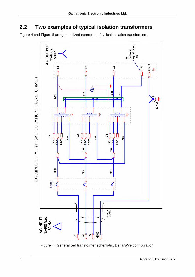
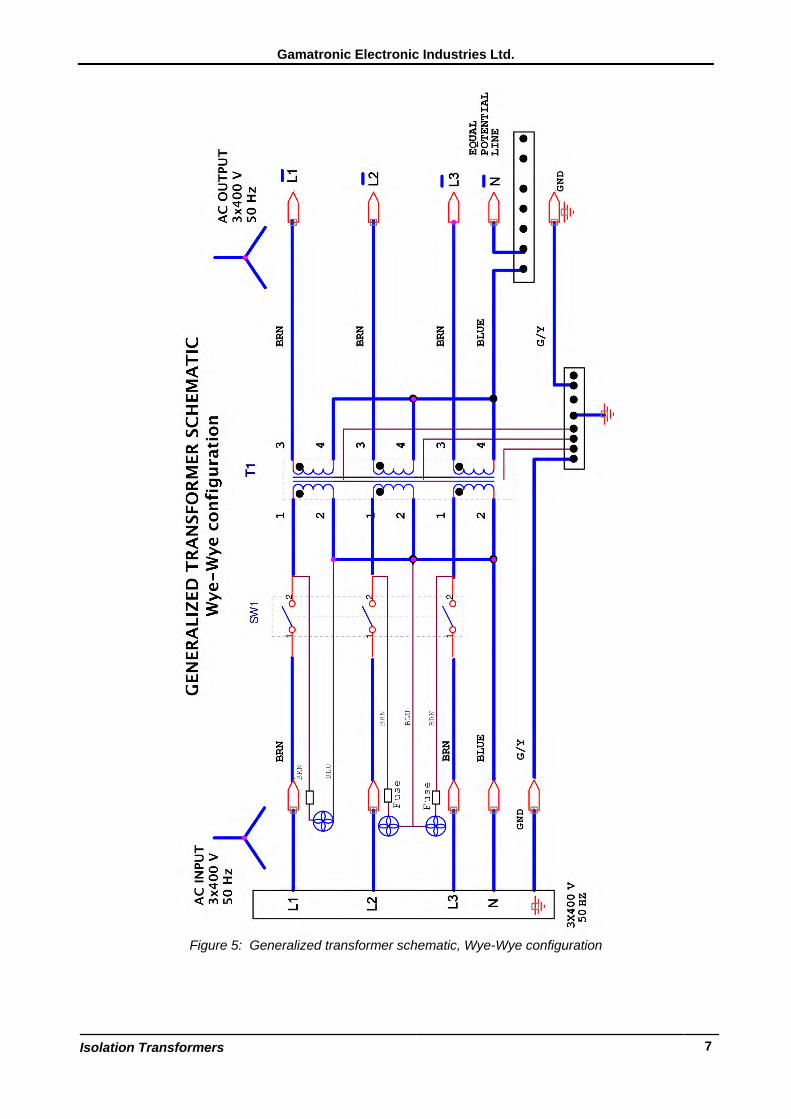
2.2 Two examples of typical isolation transformers Figure 4 and Figure 5 are generalized examples of typical isolation transformers.
Figure 4: Generalized transformer schematic, Delta-Wye configuration
Gamatronic Electronic Industries Ltd.
Isolation Transformers
7
Figure 5: Generalized transformer schematic, Wye-Wye configuration
Gamatronic Electronic Industries Ltd.
Isolation Transformers 8
2.3 Installation instructions
To install a Gamatronic 3/3 Delta-Wye or Wye-Wye isolation transformer.
1. Verify that the circuit breaker on the feed board for the transformer input line is rated for at least 10 x Inominal, to eliminate the influence of current transients.
2. Ensure that the feed cables are voltage free before beginning installation and that the feed circuit breaker will remain in the OFF position.
3. Verify that the transformer's input circuit breaker is in the OFF position.
4. Connect the transformer's input ground cable to the building ground system.
5. Connect the input line from the feed board to the transformer's input terminals.
6 Connect the transformer's output phases to the load, including the ground terminal.
7. Switch ON the transformer circuit breaker(s).
Gamatronic Electronic Industries Ltd.
Isolation Transformers
9
3. TECHNICAL SPECIFICATIONS
15-150 kVA Isolation Transformers, 3X400 Vac, 50 Hz
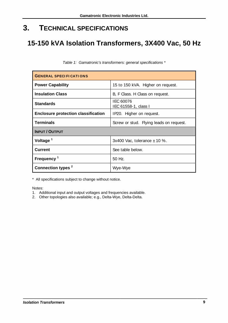
Table 1: Gamatronic's transformers: general specifications *
* All specifications subject to change without notice. Notes: 1. Additional input and output voltages and frequencies available. 2. Other topologies also available; e.g., Delta-Wye, Delta-Delta.
GENERAL SPECIFICATIONS
Power Capability 15 to 150 kVA. Higher on request.
Insulation Class B, F Class. H Class on request.
Standards IEC 60076 IEC 61558-1, class I
Enclosure protection classification IP20. Higher on request.
Terminals Screw or stud. Flying leads on request.
INPUT / OUTPUT
Voltage 1 3x400 Vac, tolerance ±10 %.
Current See table below.
Frequency 1 50 Hz.
Connection types 2 Wye-Wye

Gamatronic Electronic Industries Ltd.
Isolation Transformers 10
This page left blank deliberately.
Gamatronic Electronic Industries Ltd.
Isolation Transformers
11
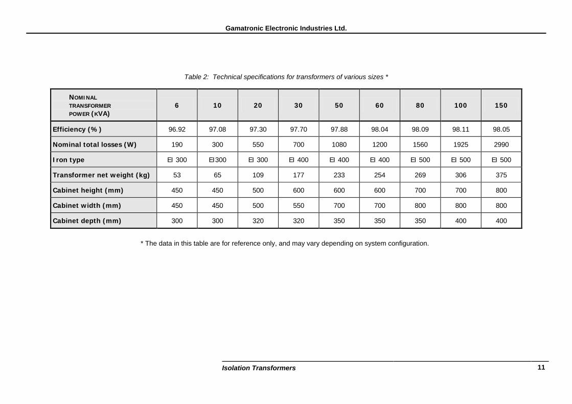
Table 2: Technical specifications for transformers of various sizes *
NOMINAL TRANSFORMER POWER (KVA)
6 10 20 30 50 60 80 100 150
Efficiency (%) 96.92 97.08 97.30 97.70 97.88 98.04 98.09 98.11 98.05
Nominal total losses (W) 190 300 550 700 1080 1200 1560 1925 2990
Iron type EI 300 EI300 EI 300 EI 400 EI 400 EI 400 EI 500 EI 500 EI 500
Transformer net weight (kg) 53 65 109 177 233 254 269 306 375
Cabinet height (mm) 450 450 500 600 600 600 700 700 800
Cabinet width (mm) 450 450 500 550 700 700 800 800 800
Cabinet depth (mm) 300 300 320 320 350 350 350 400 400
* The data in this table are for reference only, and may vary depending on system configuration.


![[PPT]Three-Phase Inverters - Welcome - Faculty Pages - … · Web viewThree-Phase Inverters Consider three single-phase inverters in parallel, driven 120 apart. Three-Phase Inverter](https://img.pdfslide.net/doc/110x75/5b08de6f7f8b9a520e8d510f/pptthree-phase-inverters-welcome-faculty-pages-viewthree-phase-inverters.jpg)