Embed Size (px)
Citation preview
Three Phase Motor with Squirrel Cage Rotor for Low Voltage TMC Series
THE NEW POWER GENERATION

Subject to alteration - 2 -
UniTec Delivery Program • Low Voltage Motors
- Squirrel Cage Motors - Slip Ring Motors - Hoist Motors - Geared Motors
• High Voltage Motors - Squirrel Cage Motors - Slip Ring Motors
• DC Motors - Standard Series - Mill AISE Motors
• Generators - asynchronous Generators - synchronous Generators
• Transformer - Oil Transformer - Dry Type Transformer - Cast Resin Transformer
• Starter - Oil cooled - Air cooled - Liquid Reostart
• Frequency Inverter - Low Voltage - Medium Voltage
• Thyristor Units
• Switchboards
Subject to alteration - 3 -
Three phase motor with squirrel cage rotor
Content List
Page Introduction 4 Technical Information Mounting Arrangement acc. to IEC 5 Selection of Bearings and Re-Lubrication 6 Cantilever Forces 7 Technical Data 2 – pole 8 4 – pole 9 6 – pole 10 8 – pole 11 10 – pole 12 Dimensions Mounting B3 Frame Size 63 – 400 13 – 17 Mounting B5 Frame Size 63 – 400 18 – 22 Mounting B35 Frame Size 63 – 400 23 – 27
Subject to alteration - 4 -
Three phase motor with squirrel cage rotor
Technical Information
National Standards The motors comply with various national standards. The following have been harmonized with IEC publication 60 034-1 or replaced by DIN EN 60 034-1, so that the motors can be operated at nominal voltage In specific the following standards apply:
• General Requirements for rotating electric machines IEC 60 034-1
• Types of Construction and Installation IEC 60 034-7
• Degrees of Protection of rotating machines IEC 60 034-5
• Methods of Cooling of rotating machines IEC 60 034-6
• Terminal Designation and Direction of Rotation of rotating machines IEC 60 034-8 Electrical Execution Ratings The Nominal Ratings mentioned in the selection table refer to S1 Continuous duty at nominal voltage and nominal frequency. The max. permissible ambient temperature is 40°C and the installation height is limited to max. 1.000 m above sea level. The motors are designed in Insulation Class F with temperature rise acc. to class B. Voltage and Frequency In Standard version all motors are designed in the range of 380 – 420 V, 50 Hz / 420 – 480 V, 60 Hz. From 3,0 kW the winding connection is Delta, below in Star. On request other voltages up to 690 V can be supplied. Mechanical Execution Motor Housing All motors are designed in cast iron version and can be supplied in various different mounting arrangements acc. to selection table of page No. 5. Protection Class All motors are designed in protection class IP 55 for installation in humid and dusty atmosphere. Higher protection classes available on request. Cooling Method The motors are designed acc. to IC 411with an unidirectional fan. Shaft and Balancing All motors are designed with one free shaft end and dynamically balanced with half key. On request motors can be manufactured on extra price with second shaft end. Bearings All motors are designed with two identical ball bearings of SKF, FAG or NSK brand On request from frame size 180 motors can be designed on extra price with roller bearings for increased cantilever forces. Motor from frame size 180 are designed with regreaseable bearings. The bearings for smaller motors are prelubricated The nominal bearing life of motors with horizontal type of construction is at least 40.000 hours if there is no additional axial loading at the output coupling. With maximum permitted loads it is at least 20.000 hours Terminal Box All motors are designed in normal version with terminal box location on top. On request the location can be changed to side up to frame size 355

Subject to alteration - 5 -
Three phase motor with squirrel cage rotor
Mounting Arrangement acc. to IEC Mounting Arrangement IEC 34 - 7 1992 Mounting Arrangement IEC 34 - 7 1992
Code I Code II Code I Code II
IM B3 IM 1001
IM B3 IM 1001
IM B5 IM 3001
IM B5 IM 3001
IM B6 IM 1051
IM B6 IM 1051
IM B7 IM 1061
IM B7 IM 1061
IM B8 IM 1071
IM B8 IM 1071
IM B14 IM 3601
IM B14 IM 3601
IM B34 IM 2101
IM B34 IM 2101
IM B35 IM 2001
IM B35 IM 2001
IM V1 IM 3011
IM V1 IM 3011
Subject to alteration - 6 -
Three phase motor with squirrel cage rotor
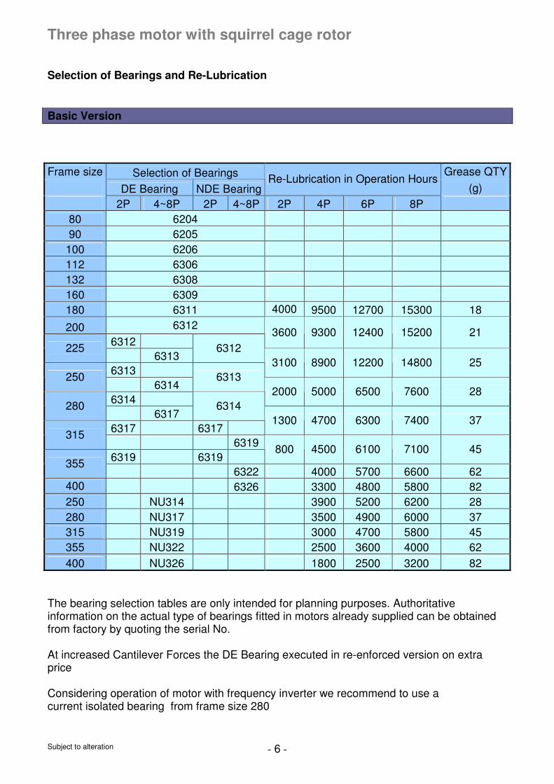
Selection of Bearings and Re-Lubrication Basic Version
Frame size Selection of Bearings Grease QTY
DE Bearing NDE Bearing Re-Lubrication in Operation Hours
(g)
2P 4~8P 2P 4~8P 2P 4P 6P 8P
80 6204
90 6205
100 6206
112 6306
132 6308
160 6309
180 6311 4000 9500 12700 15300 18
200 6312
6312 3600 9300 12400 15200 21
225 6313
6312
6313 3100 8900 12200 14800 25
250 6314
6313
6314 2000 5000 6500 7600 28
280 6317
6314
6317 6317 1300 4700 6300 7400 37
315 6319
6319 6319 800 4500 6100 7100 45
355 6322 4000 5700 6600 62
400 6326 3300 4800 5800 82
250 NU314 3900 5200 6200 28
280 NU317 3500 4900 6000 37
315 NU319 3000 4700 5800 45
355 NU322 2500 3600 4000 62
400 NU326 1800 2500 3200 82
The bearing selection tables are only intended for planning purposes. Authoritative information on the actual type of bearings fitted in motors already supplied can be obtained from factory by quoting the serial No. At increased Cantilever Forces the DE Bearing executed in re-enforced version on extra price Considering operation of motor with frequency inverter we recommend to use a current isolated bearing from frame size 280
Subject to alteration - 7 -
Three phase motor with squirrel cage rotor
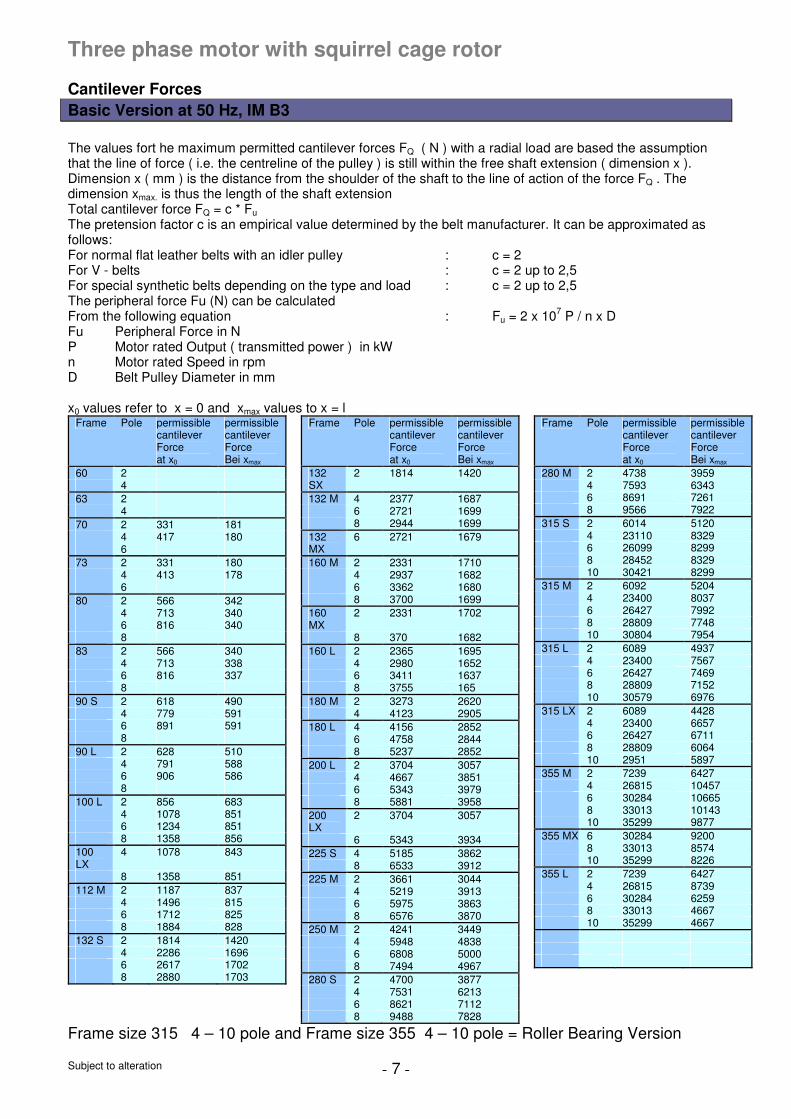
Cantilever Forces Basic Version at 50 Hz, IM B3
The values fort he maximum permitted cantilever forces FQ ( N ) with a radial load are based the assumption that the line of force ( i.e. the centreline of the pulley ) is still within the free shaft extension ( dimension x ). Dimension x ( mm ) is the distance from the shoulder of the shaft to the line of action of the force FQ . The dimension xmax. is thus the length of the shaft extension Total cantilever force FQ = c * Fu The pretension factor c is an empirical value determined by the belt manufacturer. It can be approximated as follows: For normal flat leather belts with an idler pulley : c = 2 For V - belts : c = 2 up to 2,5 For special synthetic belts depending on the type and load : c = 2 up to 2,5 The peripheral force Fu (N) can be calculated From the following equation : Fu = 2 x 10
7 P / n x D
Fu Peripheral Force in N P Motor rated Output ( transmitted power ) in kW n Motor rated Speed in rpm D Belt Pulley Diameter in mm x0 values refer to x = 0 and xmax values to x = l
Frame Pole permissible cantilever Force at x0
permissible cantilever Force Bei xmax
60 2 4
63 2 4
70 2 331 181 4 417 180 6
73 2 331 180 4 413 178 6
80 2 566 342 4 713 340 6 816 340 8
83 2 566 340 4 713 338 6 816 337 8
90 S 2 618 490 4 779 591 6 891 591 8
90 L 2 628 510 4 791 588 6 906 586 8
100 L 2 856 683 4 1078 851 6 1234 851 8 1358 856
100 LX
4 1078 843
8 1358 851
112 M 2 1187 837 4 1496 815 6 1712 825 8 1884 828
132 S 2 1814 1420 4 2286 1696 6 2617 1702 8 2880 1703
Frame Pole permissible cantilever Force at x0
permissible cantilever Force Bei xmax
132 SX
2 1814 1420
132 M 4 2377 1687 6 2721 1699 8 2944 1699
132 MX
6 2721 1679
160 M 2 2331 1710 4 2937 1682 6 3362 1680 8 3700 1699
160 MX
2 2331 1702
8 370 1682
160 L 2 2365 1695 4 2980 1652 6 3411 1637 8 3755 165
180 M 2 3273 2620 4 4123 2905
180 L 4 4156 2852 6 4758 2844 8 5237 2852
200 L 2 3704 3057 4 4667 3851 6 5343 3979 8 5881 3958
200 LX
2 3704 3057
6 5343 3934
225 S 4 5185 3862 8 6533 3912
225 M 2 3661 3044 4 5219 3913 6 5975 3863 8 6576 3870
250 M 2 4241 3449 4 5948 4838 6 6808 5000 8 7494 4967
280 S 2 4700 3877 4 7531 6213 6 8621 7112 8 9488 7828
Frame Pole permissible cantilever Force at x0
permissible cantilever Force Bei xmax
280 M 2 4738 3959 4 7593 6343 6 8691 7261 8 9566 7922
315 S 2 6014 5120 4 23110 8329 6 26099 8299 8 28452 8329 10 30421 8299
315 M 2 6092 5204 4 23400 8037 6 26427 7992 8 28809 7748 10 30804 7954
315 L 2 6089 4937 4 23400 7567 6 26427 7469 8 28809 7152 10 30579 6976
315 LX 2 6089 4428 4 23400 6657 6 26427 6711 8 28809 6064 10 2951 5897
355 M 2 7239 6427 4 26815 10457 6 30284 10665 8 33013 10143 10 35299 9877
355 MX 6 30284 9200 8 33013 8574 10 35299 8226
355 L 2 7239 6427 4 26815 8739 6 30284 6259 8 33013 4667 10 35299 4667
Frame size 315 4 – 10 pole and Frame size 355 4 – 10 pole = Roller Bearing Version
Subject to alteration - 8 -
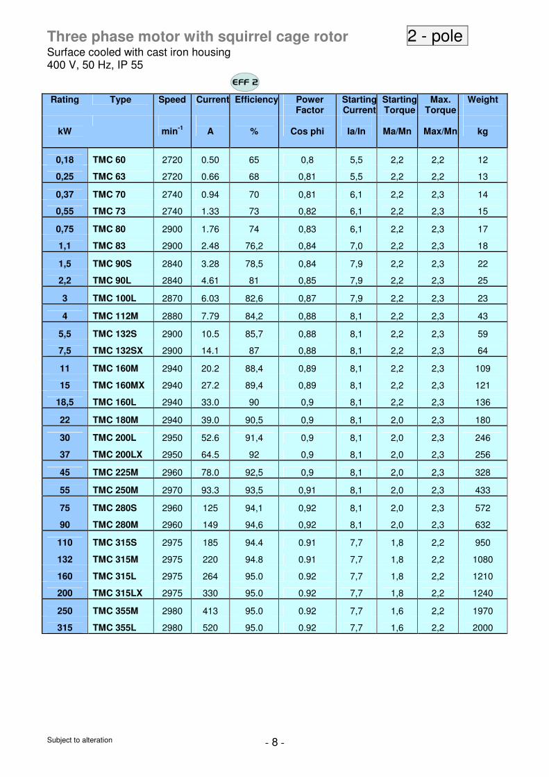
Three phase motor with squirrel cage rotor 2 - pole
Surface cooled with cast iron housing 400 V, 50 Hz, IP 55
Rating
Type Speed Current Efficiency Power
Factor StartingCurrent
Starting Torque
Max. Torque
Weight
kW
min-1
A
%
Cos phi
Ia/In
Ma/Mn
Max/Mn
kg
0,18 TMC 60 2720 0.50 65 0,8 5,5 2,2 2,2 12
0,25 TMC 63 2720 0.66 68 0,81 5,5 2,2 2,2 13
0,37 TMC 70 2740 0.94 70 0,81 6,1 2,2 2,3 14
0,55 TMC 73 2740 1.33 73 0,82 6,1 2,2 2,3 15
0,75 TMC 80 2900 1.76 74 0,83 6,1 2,2 2,3 17
1,1 TMC 83 2900 2.48 76,2 0,84 7,0 2,2 2,3 18
1,5 TMC 90S 2840 3.28 78,5 0,84 7,9 2,2 2,3 22
2,2 TMC 90L 2840 4.61 81 0,85 7,9 2,2 2,3 25
3 TMC 100L 2870 6.03 82,6 0,87 7,9 2,2 2,3 23
4 TMC 112M 2880 7.79 84,2 0,88 8,1 2,2 2,3 43
5,5 TMC 132S 2900 10.5 85,7 0,88 8,1 2,2 2,3 59
7,5 TMC 132SX 2900 14.1 87 0,88 8,1 2,2 2,3 64
11 TMC 160M 2940 20.2 88,4 0,89 8,1 2,2 2,3 109
15 TMC 160MX 2940 27.2 89,4 0,89 8,1 2,2 2,3 121
18,5 TMC 160L 2940 33.0 90 0,9 8,1 2,2 2,3 136
22 TMC 180M 2940 39.0 90,5 0,9 8,1 2,0 2,3 180
30 TMC 200L 2950 52.6 91,4 0,9 8,1 2,0 2,3 246
37 TMC 200LX 2950 64.5 92 0,9 8,1 2,0 2,3 256
45 TMC 225M 2960 78.0 92,5 0,9 8,1 2,0 2,3 328
55 TMC 250M 2970 93.3 93,5 0,91 8,1 2,0 2,3 433
75 TMC 280S 2960 125 94,1 0,92 8,1 2,0 2,3 572
90 TMC 280M 2960 149 94,6 0,92 8,1 2,0 2,3 632
110 TMC 315S 2975 185 94.4 0.91 7,7 1,8 2,2 950
132 TMC 315M 2975 220 94.8 0.91 7,7 1,8 2,2 1080
160 TMC 315L 2975 264 95.0 0.92 7,7 1,8 2,2 1210
200 TMC 315LX 2975 330 95.0 0.92 7,7 1,8 2,2 1240
250 TMC 355M 2980 413 95.0 0.92 7,7 1,6 2,2 1970
315 TMC 355L 2980 520 95.0 0.92 7,7 1,6 2,2 2000
Subject to alteration - 9 -
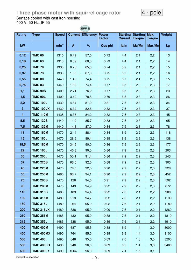
Three phase motor with squirrel cage rotor 4 - pole
Surface cooled with cast iron housing 400 V, 50 Hz, IP 55
Rating
Type Speed Current Efficiency Power Factor
Starting Current
Starting Torque
Max. Torque
Weight
kW
min-1
A
%
Cos phi
Ia/In
Ma/Mn
Max/Mn
kg
0,12 TMC 60 1310 0.42 57,0 0,72 4,4 2,1 2,2 13
0,18 TMC 63 1310 0.59 60,0 0,73 4,4 2,1 2,2 14
0,25 TMC 70 1330 0.75 65,0 0,74 5,2 2,1 2,2 15
0,37 TMC 73 1330 1.06 67,0 0,75 5,2 2,1 2,2 16
0,55 TMC 80 1440 1.42 74,4 0,75 5,7 2,4 2,3 15
0,75 TMC 83 1440 1.89 74,4 0,77 6,5 2,3 2,3 17
1,1 TMC 90S 1400 2.71 76,2 0,77 6,5 2,3 2,3 23
1,5 TMC 90L 1400 3.49 78,5 0,79 6,5 2,3 2,3 26
2,2 TMC 100L 1430 4.84 81,0 0,81 7,5 2,3 2,3 34
3 TMC 100LX 1430 6.39 82,6 0,82 7,5 2,3 2,3 37
4 TMC 112M 1435 8.36 84,2 0,82 7,5 2,3 2,3 45
5,5 TMC 132S 1440 11.2 85,7 0,83 7,5 2,3 2,3 65
7,5 TMC 132M 1440 14.8 87,0 0,84 7,5 2,3 2,3 78
11 TMC 160M 1470 21.4 88,4 0,84 8,9 2,2 2,3 118
15 TMC 160L 1470 28.5 89,4 0,85 8,9 2,2 2,3 138
18,5 TMC 180M 1470 34.5 90,0 0,86 7,9 2,2 2,3 177
22 TMC 180L 1470 40.8 90,5 0,86 7,9 2,2 2,3 203
30 TMC 200L 1470 55.1 91,4 0,86 7,9 2,2 2,3 243
37 TMC 225S 1475 66.0 92,0 0,88 7,9 2,2 2,3 305
45 TMC 225M 1475 78.0 92,5 0,90 7,9 2,2 2,3 328
55 TMC 250M 1480 93.7 94,1 0,90 7,9 2,2 2,3 452
75 TMC 280S 1475 126 94,6 0,91 7,9 2,2 2,3 592
90 TMC 280M 1475 149 94,9 0,92 7,9 2,2 2,3 672
110 TMC 315S 1480 183 94,4 0,92 7,6 2,1 2,2 980
132 TMC 315M 1480 219 94,7 0,92 7,6 2,1 2,2 1130
160 TMC 315L 1480 264 95,0 0,92 7,6 2,1 2,2 1180
200 TMC 315LX 1480 338 95,0 0,90 7,6 2,1 2,2 1260
250 TMC 355M 1485 432 95,0 0,88 7,6 2,1 2,2 1810
315 TMC 355L 1485 538 95,0 0,89 7,6 2,1 2,2 1910
400 TMC 400M 1490 687 95,5 0,88 6,9 1,4 3,0 3000
450 TMC 400MX 1490 764 95,5 0,89 6,9 1,4 3,0 3100
500 TMC 400L 1490 848 95,6 0,89 7,0 1,3 3,0 3200
560 TMC 400LQ 1490 946 96,0 0,89 6,5 1,4 3,0 3400
630 TMC 400LX 1490 1064 96,0 0,89 7,1 1,5 3,1
Subject to alteration - 10 -
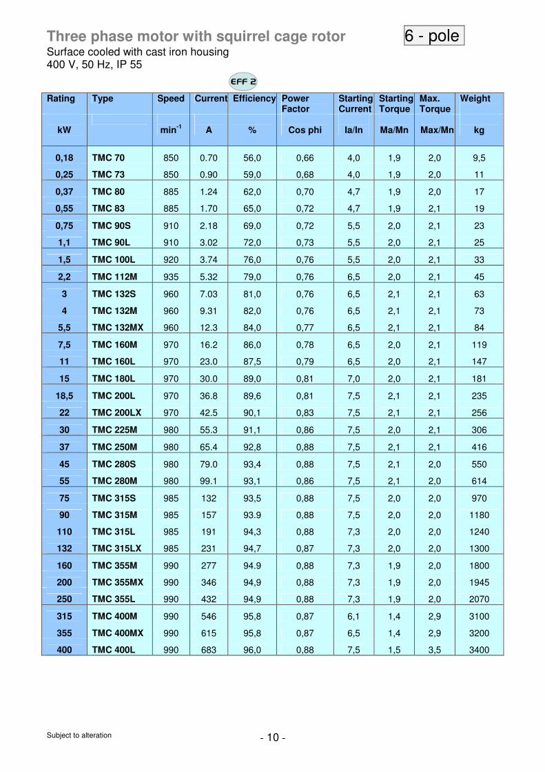
Three phase motor with squirrel cage rotor 6 - pole
Surface cooled with cast iron housing 400 V, 50 Hz, IP 55
Rating
Type Speed Current Efficiency Power Factor
Starting Current
Starting Torque
Max. Torque
Weight
kW
min-1
A
%
Cos phi
Ia/In
Ma/Mn
Max/Mn
kg
0,18 TMC 70 850 0.70 56,0 0,66 4,0 1,9 2,0 9,5
0,25 TMC 73 850 0.90 59,0 0,68 4,0 1,9 2,0 11
0,37 TMC 80 885 1.24 62,0 0,70 4,7 1,9 2,0 17
0,55 TMC 83 885 1.70 65,0 0,72 4,7 1,9 2,1 19
0,75 TMC 90S 910 2.18 69,0 0,72 5,5 2,0 2,1 23
1,1 TMC 90L 910 3.02 72,0 0,73 5,5 2,0 2,1 25
1,5 TMC 100L 920 3.74 76,0 0,76 5,5 2,0 2,1 33
2,2 TMC 112M 935 5.32 79,0 0,76 6,5 2,0 2,1 45
3 TMC 132S 960 7.03 81,0 0,76 6,5 2,1 2,1 63
4 TMC 132M 960 9.31 82,0 0,76 6,5 2,1 2,1 73
5,5 TMC 132MX 960 12.3 84,0 0,77 6,5 2,1 2,1 84
7,5 TMC 160M 970 16.2 86,0 0,78 6,5 2,0 2,1 119
11 TMC 160L 970 23.0 87,5 0,79 6,5 2,0 2,1 147
15 TMC 180L 970 30.0 89,0 0,81 7,0 2,0 2,1 181
18,5 TMC 200L 970 36.8 89,6 0,81 7,5 2,1 2,1 235
22 TMC 200LX 970 42.5 90,1 0,83 7,5 2,1 2,1 256
30 TMC 225M 980 55.3 91,1 0,86 7,5 2,0 2,1 306
37 TMC 250M 980 65.4 92,8 0,88 7,5 2,1 2,1 416
45 TMC 280S 980 79.0 93,4 0,88 7,5 2,1 2,0 550
55 TMC 280M 980 99.1 93,1 0,86 7,5 2,1 2,0 614
75 TMC 315S 985 132 93,5 0,88 7,5 2,0 2,0 970
90 TMC 315M 985 157 93.9 0,88 7,5 2,0 2,0 1180
110 TMC 315L 985 191 94,3 0,88 7,3 2,0 2,0 1240
132 TMC 315LX 985 231 94,7 0,87 7,3 2,0 2,0 1300
160 TMC 355M 990 277 94.9 0,88 7,3 1,9 2,0 1800
200 TMC 355MX 990 346 94,9 0,88 7,3 1,9 2,0 1945
250 TMC 355L 990 432 94,9 0,88 7,3 1,9 2,0 2070
315 TMC 400M 990 546 95,8 0,87 6,1 1,4 2,9 3100
355 TMC 400MX 990 615 95,8 0,87 6,5 1,4 2,9 3200
400 TMC 400L 990 683 96,0 0,88 7,5 1,5 3,5 3400
Subject to alteration - 11 -
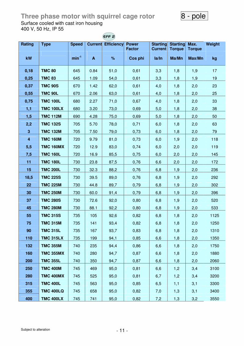
Three phase motor with squirrel cage rotor 8 - pole
Surface cooled with cast iron housing 400 V, 50 Hz, IP 55
Rating
Type Speed Current Efficiency Power Factor
Starting Current
Starting Torque
Max. Torque
Weight
kW
min-1
A
%
Cos phi
Ia/In
Ma/Mn
Max/Mn
kg
0,18 TMC 80 645 0.84 51,0 0,61 3,3 1,8 1,9 17
0,25 TMC 83 645 1.09 54,0 0,61 3,3 1,8 1,9 19
0,37 TMC 90S 670 1.42 62,0 0,61 4,0 1,8 2,0 23
0,55 TMC 90L 670 2.06 63,0 0,61 4,0 1,8 2,0 25
0,75 TMC 100L 680 2.27 71,0 0,67 4,0 1,8 2,0 33
1,1 TMC 100LX 680 3.20 73,0 0,69 5,0 1,8 2,0 38
1,5 TMC 112M 690 4.28 75,0 0,69 5,0 1,8 2,0 50
2,2 TMC 132S 705 5.70 78,0 0,71 6,0 1,8 2,0 63
3 TMC 132M 705 7.50 79,0 0,73 6,0 1,8 2,0 79
4 TMC 160M 720 9.79 81,0 0,73 6,0 1,9 2,0 118
5,5 TMC 160MX 720 12.9 83,0 0,74 6,0 2,0 2,0 119
7,5 TMC 160L 720 16.9 85,5 0,75 6,0 2,0 2,0 145
11 TMC 180L 730 23.8 87,5 0,76 6,6 2,0 2,0 172
15 TMC 200L 730 32.3 88,2 0,76 6,8 1,9 2,0 236
18,5 TMC 225S 730 39.5 89,0 0,76 6,8 1,9 2,0 292
22 TMC 225M 730 44.8 89,7 0,79 6,8 1,9 2,0 302
30 TMC 250M 730 60.0 91,4 0,79 6,8 1,9 2,0 396
37 TMC 280S 730 72.6 92,0 0,80 6,8 1,9 2,0 520
45 TMC 280M 730 88.1 92,2 0,80 6,8 1,9 2,0 533
55 TMC 315S 735 105 92,6 0,82 6,8 1,8 2,0 1125
75 TMC 315M 735 141 93,4 0,82 6,8 1,8 2,0 1250
90 TMC 315L 735 167 93,7 0,83 6,8 1,8 2,0 1310
110 TMC 315LX 735 199 94,1 0,85 6,6 1,8 2,0 1350
132 TMC 355M 740 235 94,4 0,86 6,6 1,8 2,0 1750
160 TMC 355MX 740 280 94,7 0,87 6,6 1,8 2,0 1880
200 TMC 355L 740 350 94,7 0,87 6,6 1,8 2,0 2060
250 TMC 400M 745 469 95,0 0,81 6,6 1,2 3,4 3100
280 TMC 400MX 745 525 95,0 0,81 6,7 1,2 3,4 3200
315 TMC 400L 745 563 95,0 0,85 6,5 1,1 3,1 3300
355 TMC 400LQ 745 658 95,0 0,82 7,0 1,3 3,1 3400
400 TMC 400LX 745 741 95,0 0,82 7,2 1,3 3,2 3550

Subject to alteration - 12 -
Three phase motor with squirrel cage rotor 10 - pole Surface cooled with cast iron housing 400 V, 50 Hz, IP 55
Rating
Type Speed Current Efficiency Power Factor
Starting Current
Starting Torque
Max. Torque
Weight
kW
min-1
A
%
Cos phi
Ia/In
Ma/Mn
Max/Mn
kg
45 TMC 315S 590 95 91,5 0,75 6,0 1,3 2,0 91.5
55 TMC 315M 590 115 92,0 0,75 6,0 1,3 2,0 92
75 TMC 315L 590 154 92,5 0,76 6,0 1,3 2,0 92.5
90 TMC 315LX 590 181 93 0,77 6,0 1,3 2,0 93
110 TMC 355M 590 219 93,2 0,78 6,0 1,3 2,0 1515
132 TMC 355MX 590 261 93,5 0,78 6,0 1,3 2,0 1630
160 TMC 355L 590 317 93,5 0,78 6,0 1,3 2,0 1795
Subject to alteration - 13 -
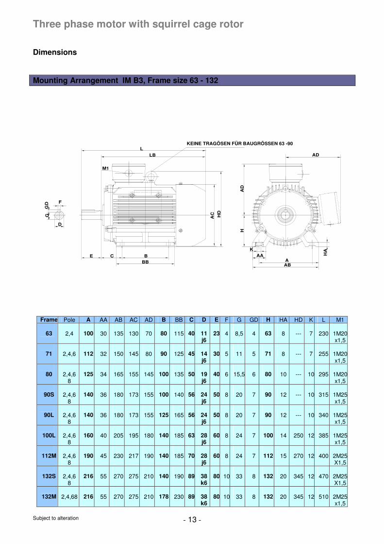
Three phase motor with squirrel cage rotor
Dimensions Mounting Arrangement IM B3, Frame size 63 - 132
GG
D
KEINE TRAGÖSEN FÜR BAUGRÖSSEN 63 -90
D
F
M1
AD
HD
AC
L
LB
E CBBB
AD
KAA
ABA
HA
H H
Frame Pole A AA AB AC AD B BB C D E F G GD H HA HD K L M1
63
2,4
100
30
135
130
70
80
115
40
11 j6
23
4
8,5
4
63
8
---
7
230
1M20x1,5
71
2,4,6
112
32
150
145
80
90
125
45
14 j6
30
5
11
5
71
8
---
7
255
1M20x1,5
80
2,4,6
8
125
34
165
155
145
100
135
50
19 j6
40
6
15,5
6
80
10
---
10
295
1M20x1,5
90S
2,4,6
8
140
36
180
173
155
100
140
56
24 j6
50
8
20
7
90
12
---
10
315
1M25x1,5
90L
2,4,6
8
140
36
180
173
155
125
165
56
24 j6
50
8
20
7
90
12
---
10
340
1M25x1,5
100L
2,4,6
8
160
40
205
195
180
140
185
63
28 j6
60
8
24
7
100
14
250
12
385
1M25x1,5
112M
2,4,6
8
190
45
230
217
190
140
185
70
28 j6
60
8
24
7
112
15
270
12
400
2M25X1,5
132S
2,4,6
8
216
55
270
275
210
140
190
89
38 k6
80
10
33
8
132
20
345
12
470
2M25X1,5
132M
2,4,68
216
55
270
275
210
178
230
89
38 k6
80
10
33
8
132
20
345
12
510
2M25x1,5
Subject to alteration - 14 -
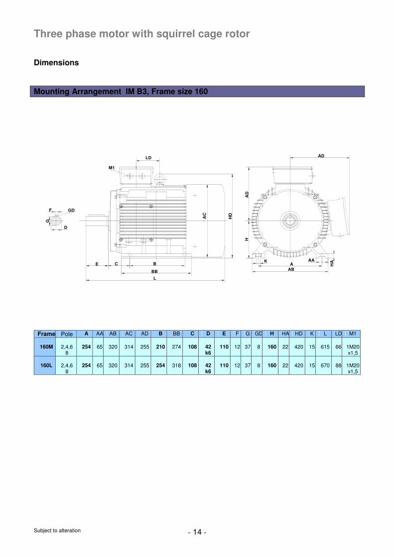
Three phase motor with squirrel cage rotor
Dimensions Mounting Arrangement IM B3, Frame size 160
C B
BB
E
L
AAB
HA
HA
D
K AA
AC
ADLD
M1
HD
GD
D
G
F
Frame Pole A AA AB AC AD B BB C D E F G GD H HA HD K L LD M1
160M
2,4,6
8
254
65
320
314
255
210
274
108
42 k6
110
12
37
8
160
22
420
15
615
66
1M20 x1,5
160L
2,4,6
8
254
65
320
314
255
254
318
108
42 k6
110
12
37
8
160
22
420
15
670
88
1M20 x1,5
Subject to alteration - 15 -
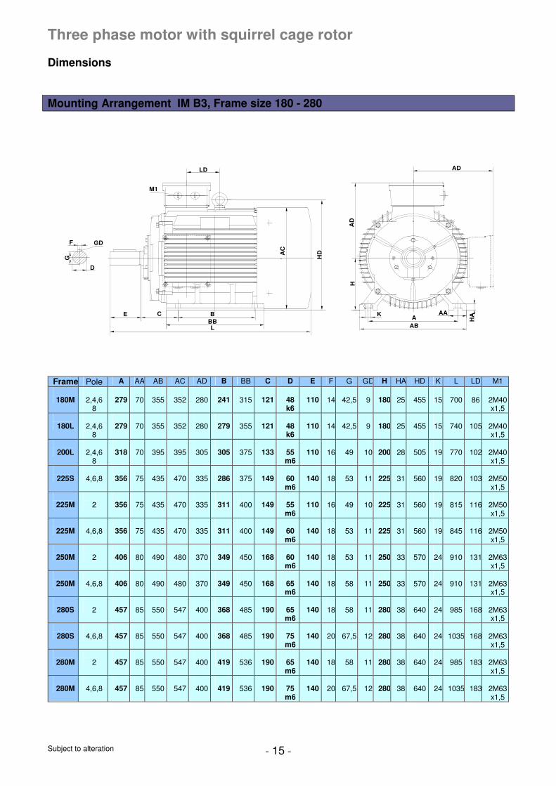
Three phase motor with squirrel cage rotor
Dimensions Mounting Arrangement IM B3, Frame size 180 - 280
C BBB
E
L
AAB
HA
HA
D
D
G
F
K AA
GD
M1
AC
AD
HD
LD
Frame Pole A AA AB AC AD B BB C D E F G GD H HA HD K L LD M1
180M
2,4,6
8
279
70
355
352
280
241
315
121
48 k6
110
14
42,5
9
180
25
455
15
700
86
2M40 x1,5
180L
2,4,6
8
279
70
355
352
280
279
355
121
48 k6
110
14
42,5
9
180
25
455
15
740
105
2M40 x1,5
200L
2,4,6
8
318
70
395
395
305
305
375
133
55 m6
110
16
49
10
200
28
505
19
770
102
2M40 x1,5
225S
4,6,8
356
75
435
470
335
286
375
149
60 m6
140
18
53
11
225
31
560
19
820
103
2M50 x1,5
225M
2
356
75
435
470
335
311
400
149
55 m6
110
16
49
10
225
31
560
19
815
116
2M50 x1,5
225M
4,6,8
356
75
435
470
335
311
400
149
60 m6
140
18
53
11
225
31
560
19
845
116
2M50 x1,5
250M
2
406
80
490
480
370
349
450
168
60 m6
140
18
53
11
250
33
570
24
910
131
2M63 x1,5
250M
4,6,8
406
80
490
480
370
349
450
168
65 m6
140
18
58
11
250
33
570
24
910
131
2M63 x1,5
280S
2
457
85
550
547
400
368
485
190
65 m6
140
18
58
11
280
38
640
24
985
168
2M63 x1,5
280S
4,6,8
457
85
550
547
400
368
485
190
75 m6
140
20
67,5
12
280
38
640
24
1035
168
2M63 x1,5
280M
2
457
85
550
547
400
419
536
190
65 m6
140
18
58
11
280
38
640
24
985
183
2M63 x1,5
280M
4,6,8
457
85
550
547
400
419
536
190
75 m6
140
20
67,5
12
280
38
640
24
1035
183
2M63 x1,5
Subject to alteration - 16 -
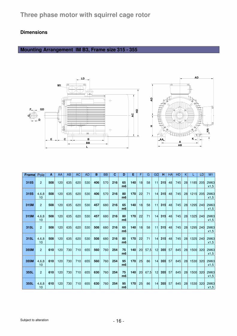
Three phase motor with squirrel cage rotor
Dimensions Mounting Arrangement IM B3, Frame size 315 - 355
F
G
D
GD
HD
LD
M1
E C BBB
L
AC
KAAA
AB
HA
D
AD
HA
Frame Pole A AA AB AC AD B BB C D E F G GD H HA HD K L LD M1
315S
2
508
120
635
620
530
406
570
216
65 m6
140
18
58
11
315
48
745
28
1185
205
2M63 x1,5
315S
4,6,8
10
508
120
635
620
530
406
570
216
80 m6
170
22
71
14
315
48
745
28
1215
205
2M63 x1,5
315M
2
508
120
635
620
530
457
680
216
65 m6
140
18
58
11
315
48
745
28
1295
240
2M63 x1,5
315M
4,6,8
10
508
120
635
620
530
457
680
216
80 m6
170
22
71
14
315
48
745
28
1325
240
2M63 x1,5
315L
2
508
120
635
620
530
508
680
216
65 m6
140
18
58
11
315
48
745
28
1295
240
2M63 x1,5
315L
4,6,8
10
508
120
635
620
530
508
680
216
80 m6
170
22
71
14
315
48
745
28
1325
240
2M63 x1,5
355M
2
610
120
730
710
655
560
760
254
75 m6
140
20
57,5
12
355
57
845
28
1500
320
2M63 x1,5
355M
4,6,8
10
610
120
730
710
655
560
760
254
95 m6
170
25
86
14
355
57
845
28
1530
320
2M63 x1,5
355L
2
610
120
730
710
655
630
760
254
75 m6
140
20
67,5
12
355
57
845
28
1500
320
2M63 x1,5
355L
4,6,8
10
610
120
730
710
655
630
760
254
95 m6
170
25
86
14
355
57
845
28
1530
320
2M63 x1,5
Subject to alteration - 17 -
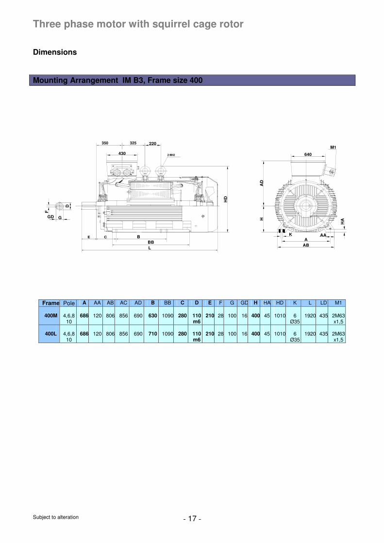
Three phase motor with squirrel cage rotor
Dimensions Mounting Arrangement IM B3, Frame size 400
2-M42
CE BBBL
350 325M1
220
430 640
F
D
GD G
HD
HA
D
HA
KA
AB
AA
Frame Pole A AA AB AC AD B BB C D E F G GD H HA HD K L LD M1
400M
4,6,8
10
686
120
806
856
690
630
1090
280
110 m6
210
28
100
16
400
45
1010
6
Ø35
1920
435
2M63 x1,5
400L
4,6,8
10
686
120
806
856
690
710
1090
280
110 m6
210
28
100
16
400
45
1010
6
Ø35
1920
435
2M63 x1,5
Subject to alteration - 18 -
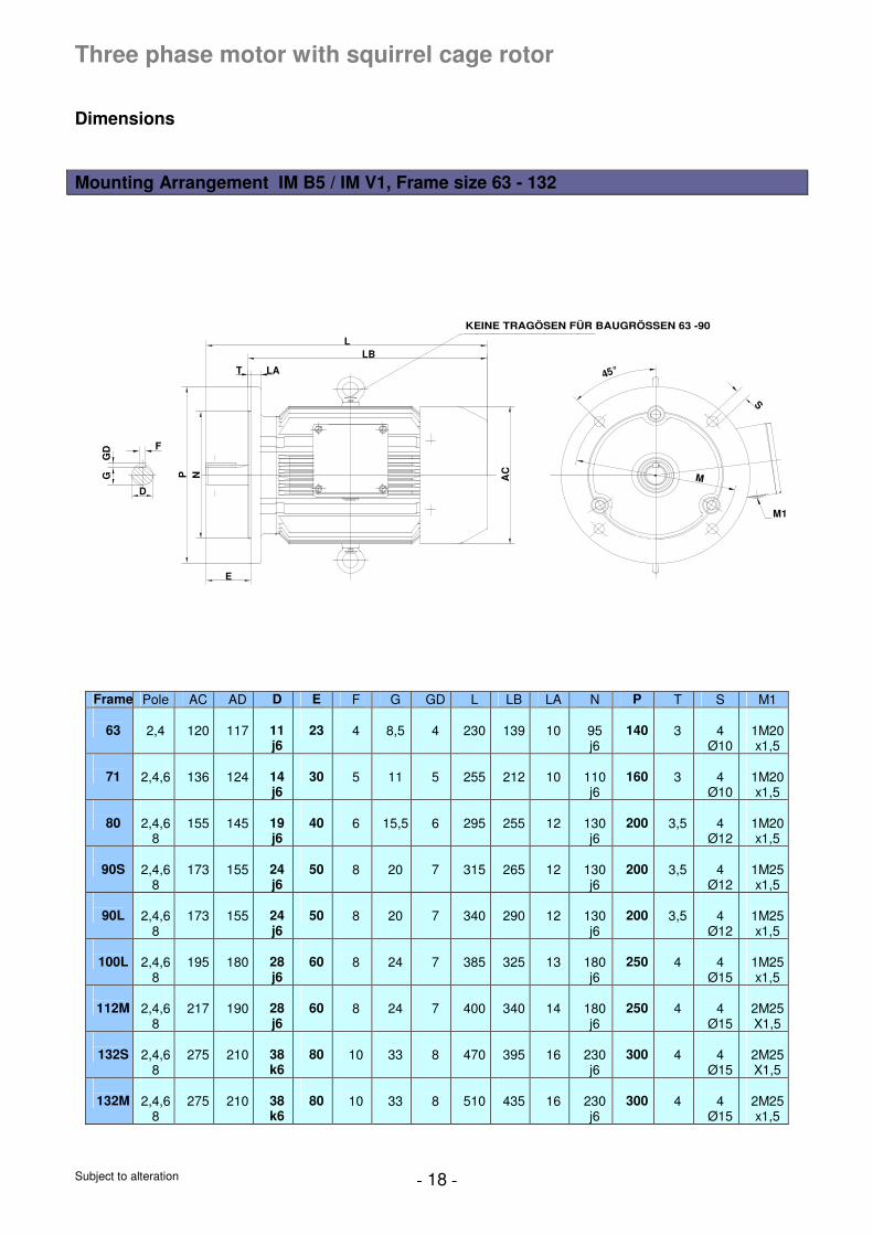
Three phase motor with squirrel cage rotor
Dimensions Mounting Arrangement IM B5 / IM V1, Frame size 63 - 132
F
D
GG
D
NP
E
T LA
LBL
AC
M
45°
S
M1
KEINE TRAGÖSEN FÜR BAUGRÖSSEN 63 -90
Frame Pole AC AD D E F G GD L LB LA N P T S M1
63
2,4
120
117
11 j6
23
4
8,5
4
230
139
10
95 j6
140
3
4
Ø10
1M20 x1,5
71
2,4,6
136
124
14 j6
30
5
11
5
255
212
10
110 j6
160
3
4
Ø10
1M20 x1,5
80
2,4,6
8
155
145
19 j6
40
6
15,5
6
295
255
12
130 j6
200
3,5
4
Ø12
1M20 x1,5
90S
2,4,6
8
173
155
24 j6
50
8
20
7
315
265
12
130 j6
200
3,5
4
Ø12
1M25 x1,5
90L
2,4,6
8
173
155
24 j6
50
8
20
7
340
290
12
130 j6
200
3,5
4
Ø12
1M25 x1,5
100L
2,4,6
8
195
180
28 j6
60
8
24
7
385
325
13
180 j6
250
4
4
Ø15
1M25 x1,5
112M
2,4,6
8
217
190
28 j6
60
8
24
7
400
340
14
180 j6
250
4
4
Ø15
2M25 X1,5
132S
2,4,6
8
275
210
38 k6
80
10
33
8
470
395
16
230 j6
300
4
4
Ø15
2M25 X1,5
132M
2,4,6
8
275
210
38 k6
80
10
33
8
510
435
16
230 j6
300
4
4
Ø15
2M25 x1,5
Subject to alteration - 19 -
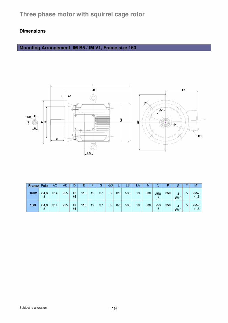
Three phase motor with squirrel cage rotor
Dimensions Mounting Arrangement IM B5 / IM V1, Frame size 160
LD
D
G
GD F
E
NP
T LA
LB
L
AC
HF
S
AD
M
45°
M1
Frame Pole AC AD D E F G GD L LB LA M N P S T M1
160M
2,4,6
8
314
255
42 k6
110
12
37
8
615
505
18
300
250 j6
350
4
Ø19
5
2M40 x1,5
160L
2,4,6
8
314
255
42 k6
110
12
37
8
670
560
18
300
250 j6
350
4
Ø19
5
2M40 x1,5
Subject to alteration - 20 -
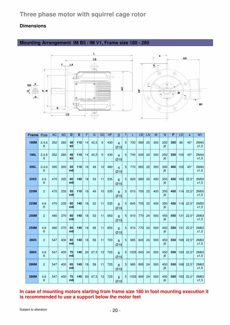
Three phase motor with squirrel cage rotor
Dimensions Mounting Arrangement IM B5 / IM V1, Frame size 180 - 280
LD
D
G
GD F
E
NP
T LA
LB
L
AC
AD
M1
MHF
a
S
Frame Pole AC AD D E F G GD HF S T L LB LA M N P LD a M1
180M
2,4,6
8
352
280
48 k6
110
14
42,5
9
430
4
Ø19
5
700
590
20
300
250 j6
350
86
45°
2M40 x1,5
180L
2,4,6
8
352
280
48 k6
110
14
42,5
9
430
4
Ø19
5
740
630
20
300
250 j6
350
105
45°
2M40 x1,5
200L
2,4,6
8
395
305
55 m6
110
16
49
10
480
4
Ø19
5
770
665
22
350
300 j6
400
102
45°
2M40 x1,5
225S
4,6 8
470
335
60 m6
140
18
53
11
535
8
Ø19
5
820
680
22
400
350 j6
450
103
22,5°
2M50 x1,5
225M
2
470
335
55 m6
110
16
49
10
535
8
Ø19
5
815
705
22
400
350 j6
450
116
22,5°
2M50 x1,5
225M
4,6 8
470
335
60 m6
140
18
53
11
535
8
Ø19
5
845
705
22
400
350 j6
450
116
22,5°
2M50 x1,5
250M
2
480
370
60 m6
140
18
53
11
650
8
Ø19
5
910
770
24
500
450 j6
550
131
22,5°
2M63 x1,5
250M
4,6 8
480
370
65 m6
140
18
58
11
650
8
Ø19
5
910
770
24
500
450 j6
550
131
22,5°
2M63 x1,5
280S
2
547
400
65 m6
140
18
58
11
720
8
Ø19
5
985
845
24
500
450 j6
550
168
22,5°
2M63 x1,5
280S
4,6 8
547
400
75 m6
140
20
67,5
12
720
8
Ø19
5
1035
845
24
500
450 j6
550
183
22,5°
2M63 x1,5
280M
2
547
400
65 m6
140
18
58
11
720
8
Ø19
5
985
895
24
500
450 j6
550
168
22,5°
2M63 x1,5
280M
4,6 8
547
400
75 m6
140
20
67,5
12
720
8
Ø19
5
1035
895
24
500
450 j6
550
183
22,5°
2M63 x1,5
In case of mounting motors starting from frame size 180 in foot mounting execution it is recommended to use a support below the motor feet
Subject to alteration - 21 -
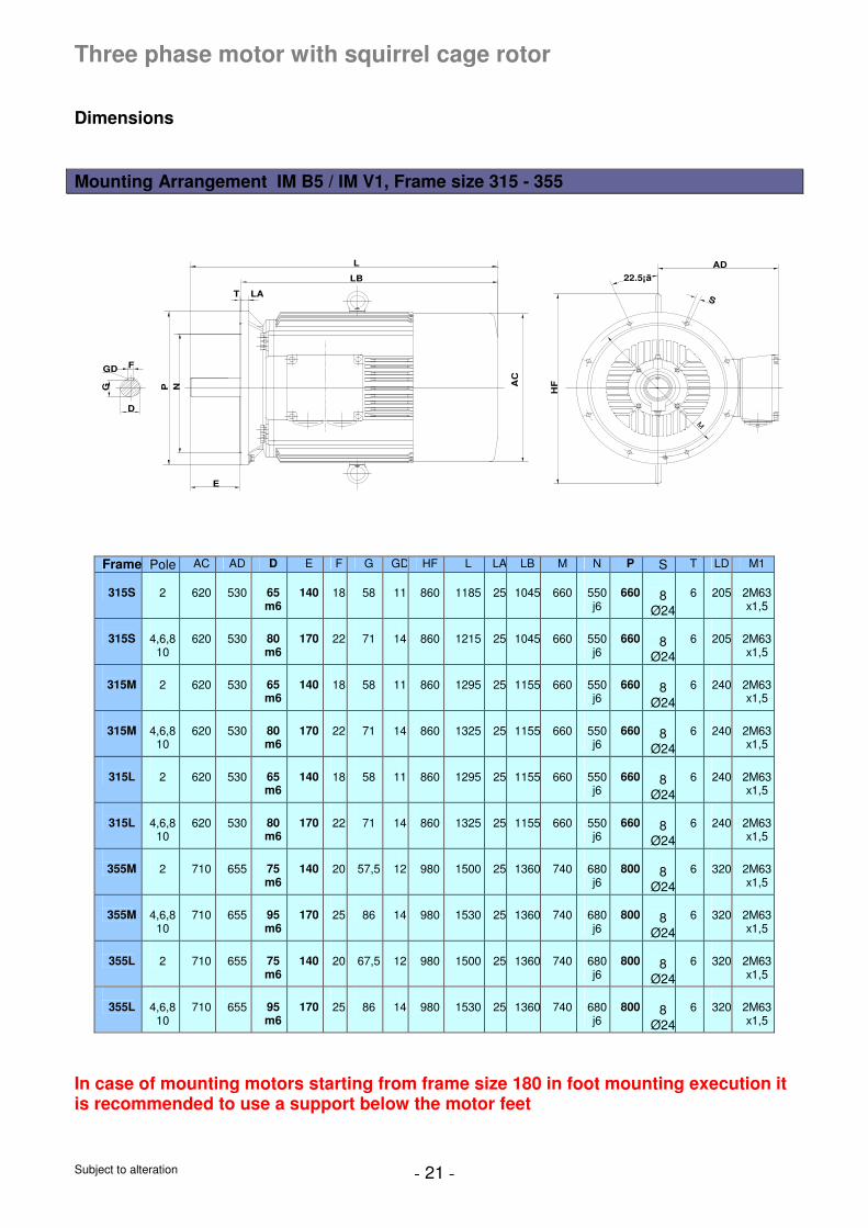
Three phase motor with squirrel cage rotor
Dimensions Mounting Arrangement IM B5 / IM V1, Frame size 315 - 355
D
G
GD F
NP
T LA
LB
L
AC
E
HF
M
22.5¡ã
S
AD
Frame Pole AC AD D E F G GD HF L LA LB M N P S T LD M1
315S
2
620
530
65 m6
140
18
58
11
860
1185
25
1045
660
550 j6
660
8
Ø24
6
205
2M63 x1,5
315S
4,6,8
10
620
530
80 m6
170
22
71
14
860
1215
25
1045
660
550 j6
660
8
Ø24
6
205
2M63 x1,5
315M
2
620
530
65 m6
140
18
58
11
860
1295
25
1155
660
550 j6
660
8
Ø24
6
240
2M63 x1,5
315M
4,6,8
10
620
530
80 m6
170
22
71
14
860
1325
25
1155
660
550 j6
660
8
Ø24
6
240
2M63 x1,5
315L
2
620
530
65 m6
140
18
58
11
860
1295
25
1155
660
550 j6
660
8
Ø24
6
240
2M63 x1,5
315L
4,6,8
10
620
530
80 m6
170
22
71
14
860
1325
25
1155
660
550 j6
660
8
Ø24
6
240
2M63 x1,5
355M
2
710
655
75 m6
140
20
57,5
12
980
1500
25
1360
740
680 j6
800
8
Ø24
6
320
2M63 x1,5
355M
4,6,8
10
710
655
95 m6
170
25
86
14
980
1530
25
1360
740
680 j6
800
8
Ø24
6
320
2M63 x1,5
355L
2
710
655
75 m6
140
20
67,5
12
980
1500
25
1360
740
680 j6
800
8
Ø24
6
320
2M63 x1,5
355L
4,6,8
10
710
655
95 m6
170
25
86
14
980
1530
25
1360
740
680 j6
800
8
Ø24
6
320
2M63 x1,5
In case of mounting motors starting from frame size 180 in foot mounting execution it is recommended to use a support below the motor feet

Subject to alteration - 22 -
Three phase motor with squirrel cage rotor
Dimensions Mounting Arrangement IM B5 / IM V1, Frame size 400
F
GD G
D NP
E
L
M
S
22.5
AD
HFAC
T LA
LBLD
M1
Frame Pole AC AD D E F G GD HF L LA LB M N P S T LD M1
400M
4,6,8
10
856
690
110 m6
210
28
100
16
1200
1920
25
1710
940
880j6
1000
8
Ø28
6
435
2M63x1,5
400L
4,6,8
10
856
690
110 m6
210
28
100
16
1200
1920
25
1710
940
880j6
1000
8
Ø28
6
435
2M63x1,5
In case of mounting motors starting from frame size 180 in foot mounting execution it is recommended to use a support below the motor feet
Subject to alteration - 23 -
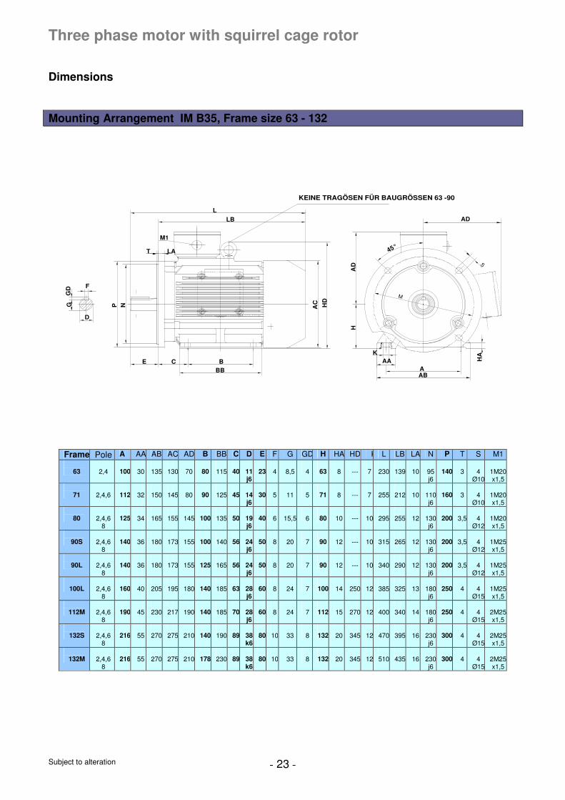
Three phase motor with squirrel cage rotor
Dimensions Mounting Arrangement IM B35, Frame size 63 - 132
AD
F
D
GG
D
NP
E C BBB
AC HD
HA
D
T LA
LB
L
AAAAB
HA
45°
M
S
M1
K
KEINE TRAGÖSEN FÜR BAUGRÖSSEN 63 -90
Frame Pole A AA AB AC AD B BB C D E F G GD H HA HD K L LB LA N P T S M1
63
2,4
100
30
135
130
70
80
115
40
11 j6
23
4
8,5
4
63
8
---
7
230
139
10
95 j6
140
3
4
Ø10
1M20x1,5
71
2,4,6
112
32
150
145
80
90
125
45
14 j6
30
5
11
5
71
8
---
7
255
212
10
110j6
160
3
4
Ø10
1M20x1,5
80
2,4,6
8
125
34
165
155
145
100
135
50
19 j6
40
6
15,5
6
80
10
---
10
295
255
12
130j6
200
3,5
4
Ø12
1M20x1,5
90S
2,4,6
8
140
36
180
173
155
100
140
56
24 j6
50
8
20
7
90
12
---
10
315
265
12
130j6
200
3,5
4
Ø12
1M25x1,5
90L
2,4,6
8
140
36
180
173
155
125
165
56
24 j6
50
8
20
7
90
12
---
10
340
290
12
130j6
200
3,5
4
Ø12
1M25x1,5
100L
2,4,6
8
160
40
205
195
180
140
185
63
28 j6
60
8
24
7
100
14
250
12
385
325
13
180j6
250
4
4
Ø15
1M25x1,5
112M
2,4,6
8
190
45
230
217
190
140
185
70
28 j6
60
8
24
7
112
15
270
12
400
340
14
180j6
250
4
4
Ø15
2M25x1,5
132S
2,4,6
8
216
55
270
275
210
140
190
89
38 k6
80
10
33
8
132
20
345
12
470
395
16
230j6
300
4
4
Ø15
2M25x1,5
132M
2,4,6
8
216
55
270
275
210
178
230
89
38 k6
80
10
33
8
132
20
345
12
510
435
16
230j6
300
4
4
Ø15
2M25x1,5
Subject to alteration - 24 -
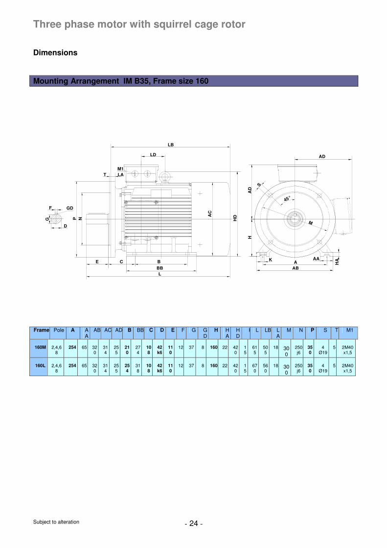
Three phase motor with squirrel cage rotor
Dimensions Mounting Arrangement IM B35, Frame size 160
E C
LBB
B
G
F
D
P
GD
N
T LAM1
LB
K AA
ABA H
A
AC
HA
D
HD
S
M
AD
45°
LD
Frame Pole A A
A AB AC AD B BB C D E F G G
D H H
A HD
K L LB LA
M N P S T M1
160M
2,4,6
8
254
65
320
314
255
210
274
108
42 k6
110
12
37
8
160
22
420
15
615
505
18
300
250 j6
350
4
Ø19
5
2M40 x1,5
160L
2,4,6
8
254
65
320
314
255
254
318
108
42 k6
110
12
37
8
160
22
420
15
670
560
18
300
250 j6
350
4
Ø19
5
2M40 x1,5
Subject to alteration - 25 -
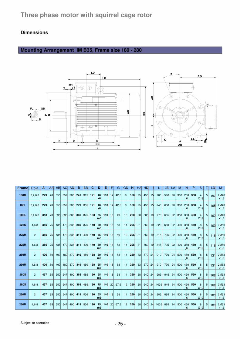
Three phase motor with squirrel cage rotor
Dimensions Mounting Arrangement IM B35, Frame size 180 - 280
E C
LBBB
G
F
D
P
GD
N
T LA
LB
K AA
ABA H
A
HDA
C
HA
D
s
LD
M1
ADa
Frame Pole A AA AB AC AD B BB C D E F G GD H HA HD K L LB LA M N P S T LD M1
180M
2,4,6,8
279
70
355
352
280
241
315
121
48 k6
110
14
42,5
9
180
25
455
15
700
590
20
300
250j6
350
4
Ø19
5
86
2M40x1,5
180L
2,4,6,8
279
70
355
352
280
279
355
121
48 k6
110
14
42,5
9
180
25
455
15
740
630
20
300
250j6
350
4
Ø19
5
105
2M40x1,5
200L
2,4,6,8
318
70
395
395
305
305
375
133
55 m6
110
16
49
10
200
28
505
19
770
665
22
350
300j6
400
4
Ø19
5
102
2M40x1,5
225S
4,6,8
356
75
435
470
335
286
375
149
60 m6
140
18
53
11
225
31
560
19
820
680
22
400
350j6
450
8
Ø19
5
103
2M50x1,5
225M
2
356
75
435
470
335
311
400
149
55 m6
110
16
49
10
225
31
560
19
815
705
22
400
350j6
450
8
Ø19
5
116
2M50x1,5
225M
4,6,8
356
75
435
470
335
311
400
149
60 m6
140
18
53
11
225
31
560
19
845
705
22
400
350j6
450
8
Ø19
5
116
2M50x1,5
250M
2
406
80
490
480
370
349
450
168
60 m6
140
18
53
11
250
33
570
24
910
770
24
500
450j6
550
8
Ø19
5
131
2M63x1,5
250M
4,6,8
406
80
490
480
370
349
450
168
65 m6
140
18
58
11
250
33
570
24
910
770
24
500
450j6
550
8
Ø19
5
131
2M63x1,5
280S
2
457
85
550
547
400
368
485
190
65 m6
140
18
58
11
280
38
640
24
985
845
24
500
450j6
550
8
Ø19
5
168
2M63x1,5
280S
4,6,8
457
85
550
547
400
368
485
190
75 m6
140
20
67,5
12
280
38
640
24
1035
845
24
500
450j6
550
8
Ø19
5
168
2M63x1,5
280M
2
457
85
550
547
400
419
536
190
65 m6
140
18
58
11
280
38
640
24
985
895
24
500
450j6
550
8
Ø19
5
183
2M63x1,5
280M
4,6,8
457
85
550
547
400
419
536
190
75 m6
140
20
67,5
12
280
38
640
24
1035
895
24
500
450j6
550
8
Ø19
5
183
2M63x1,5
Subject to alteration - 26 -
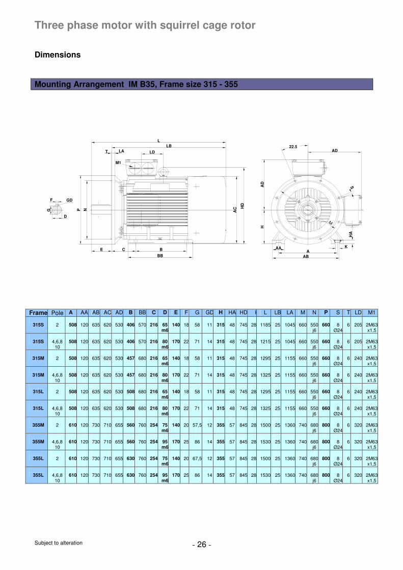
Three phase motor with squirrel cage rotor
Dimensions Mounting Arrangement IM B35, Frame size 315 - 355
G
D
GDF
T LALB
L
LD
NP AC H
D
E C B
BB
KAAA
ABH
AD
AD
M
22.5
S
HA
M1
Frame Pole A AA AB AC AD B BB C D E F G GD H HA HD K L LB LA M N P S T LD M1
315S
2
508
120
635
620
530
406
570
216
65 m6
140
18
58
11
315
48
745
28
1185
25
1045
660
550j6
660
8
Ø24
6
205
2M63x1,5
315S
4,6,8
10
508
120
635
620
530
406
570
216
80 m6
170
22
71
14
315
48
745
28
1215
25
1045
660
550j6
660
8
Ø24
6
205
2M63x1,5
315M
2
508
120
635
620
530
457
680
216
65 m6
140
18
58
11
315
48
745
28
1295
25
1155
660
550j6
660
8
Ø24
6
240
2M63x1,5
315M
4,6,8
10
508
120
635
620
530
457
680
216
80 m6
170
22
71
14
315
48
745
28
1325
25
1155
660
550j6
660
8
Ø24
6
240
2M63x1,5
315L
2
508
120
635
620
530
508
680
216
65 m6
140
18
58
11
315
48
745
28
1295
25
1155
660
550j6
660
8
Ø24
6
240
2M63x1,5
315L
4,6,8
10
508
120
635
620
530
508
680
216
80 m6
170
22
71
14
315
48
745
28
1325
25
1155
660
550j6
660
8
Ø24
6
240
2M63x1,5
355M
2
610
120
730
710
655
560
760
254
75 m6
140
20
57,5
12
355
57
845
28
1500
25
1360
740
680j6
800
8
Ø24
6
320
2M63x1,5
355M
4,6,8
10
610
120
730
710
655
560
760
254
95 m6
170
25
86
14
355
57
845
28
1530
25
1360
740
680j6
800
8
Ø24
6
320
2M63x1,5
355L
2
610
120
730
710
655
630
760
254
75 m6
140
20
67,5
12
355
57
845
28
1500
25
1360
740
680j6
800
8
Ø24
6
320
2M63x1,5
355L
4,6,8
10
610
120
730
710
655
630
760
254
95 m6
170
25
86
14
355
57
845
28
1530
25
1360
740
680j6
800
8
Ø24
6
320
2M63x1,5
Subject to alteration - 27 -
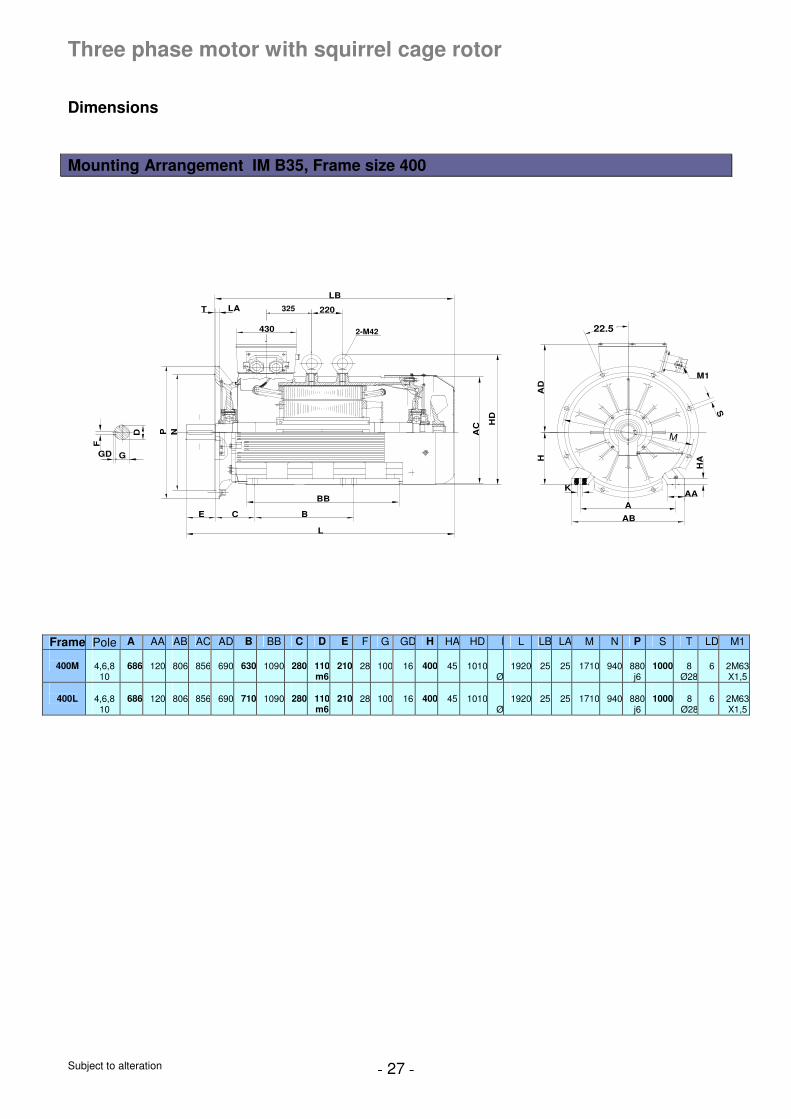
Three phase motor with squirrel cage rotor
Dimensions Mounting Arrangement IM B35, Frame size 400
2-M42
325 220
430
F
D
GD G
HD
HA
D
HA
K
22.5
M
M1
P N
E C B
BB
L
AC
T LA
LB
S
A
AB
AA
Frame Pole A AA AB AC AD B BB C D E F G GD H HA HD K L LB LA M N P S T LD M1
400M
4,6,8
10
686
120
806
856
690
630
1090
280
110m6
210
28
100
16
400
45
1010 6
Ø35
1920
25
25
1710
940
880j6
1000
8
Ø28
6
2M63X1,5
400L
4,6,8
10
686
120
806
856
690
710
1090
280
110m6
210
28
100
16
400
45
1010 6
Ø35
1920
25
25
1710
940
880j6
1000
8
Ø28
6
2M63X1,5

Subject to alteration - 28 -
UniTec Group Röntgenstrasse 1B – D – 30890 Barsinghausen
Tel. +49 – 5105 – 77879 0 Fax + 49 – 5105 – 77879 20 E-Mail: [email protected] www.unitec-group.de

![PROOF COPY [HYENG-07-6319] 001004QHYpierre/ce_old/classes/ce717/Proof… · PROOF COPY [HYENG-07-6319] 001004QHY PROOF COPY [HYENG-07-6319] 001004QHY Case Study: Flood Mitigation](https://img.pdfslide.net/doc/110x75/60888bea3cebcf6be3357dfb/proof-copy-hyeng-07-6319-001004qhy-pierreceoldclassesce717proof-proof-copy.jpg)


![[XLS] · Web view317 317 317 317 316 239 316 239 315 94 315 94 86 86 86 398 426 426 426 316 239 316 239 317 317 317 315 94 315 94 315 315 315 315 426 316 239 274 136 274 136 274 136](https://img.pdfslide.net/doc/110x75/5abaa3447f8b9a567c8bbc29/xls-view317-317-317-317-316-239-316-239-315-94-315-94-86-86-86-398-426-426-426.jpg)
![[XLS] · Web view317 317 317 317 315 94 315 94 86 86 86 426 426 426 316 239 316 239 317 317 317 315 94 315 94 315 315 315 315 426 274 136 274 136 274 136 274 136 274 188 274 188 274](https://img.pdfslide.net/doc/110x75/5abaa3447f8b9a567c8bbc31/xls-view317-317-317-317-315-94-315-94-86-86-86-426-426-426-316-239-316-239-317.jpg)


![[6319]Historia Geral Completo](https://img.pdfslide.net/doc/110x75/55cf94a2550346f57ba358e0/6319historia-geral-completo.jpg)