Embed Size (px)
Citation preview
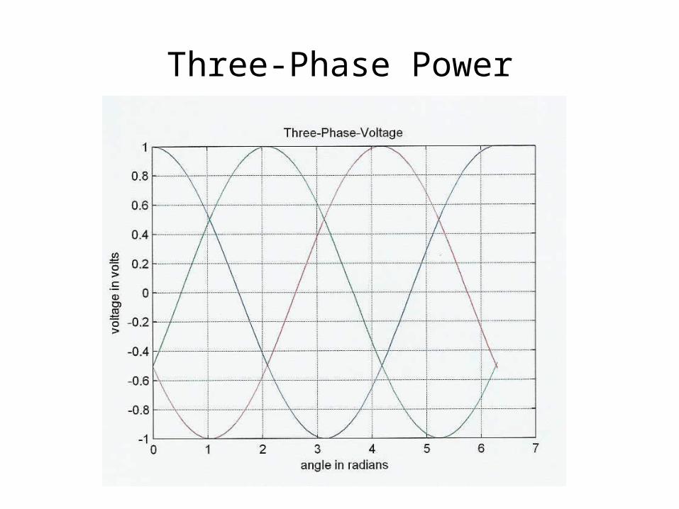
Three-Phase Power
Definitions
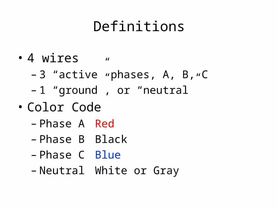
• 4 wires– 3 “active” phases, A, B, C– 1 “ground”, or “neutral”
• Color Code– Phase A Red– Phase B Black– Phase C Blue– Neutral White or Gray
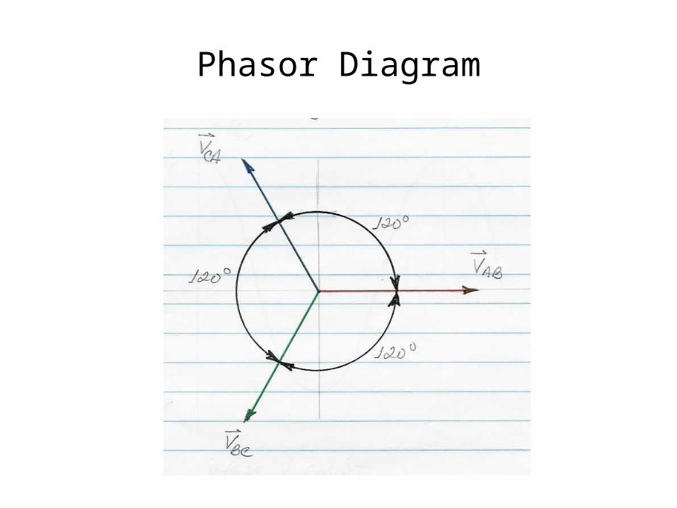
Phasor Diagram

Delta-Connected Sources
VLINE = V
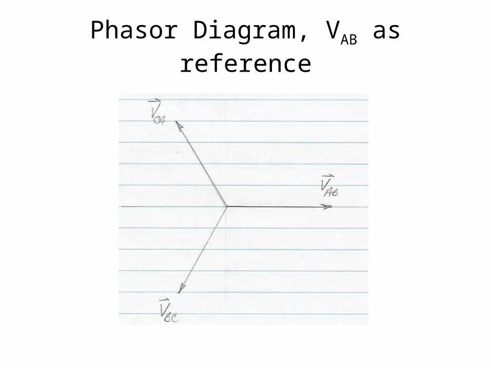
Phasor Diagram, VAB as reference
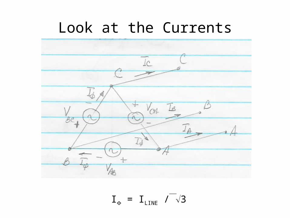
Look at the Currents
I = ILINE / 3

Y-Connected Sources
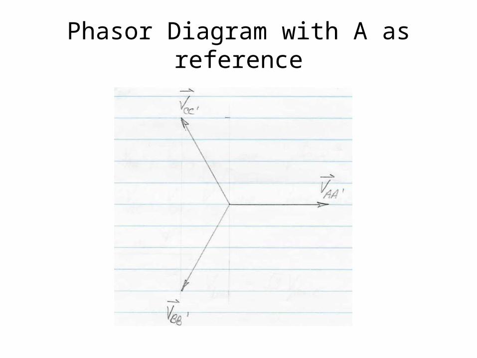
Phasor Diagram with A as reference
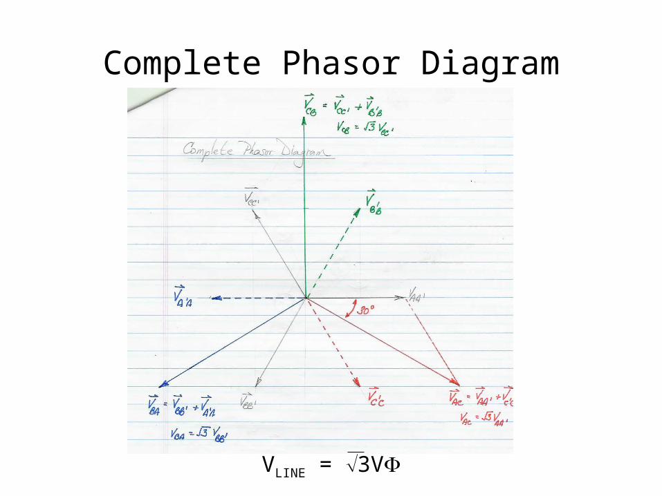
Complete Phasor Diagram
VLINE = 3V
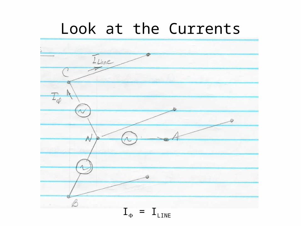
Look at the Currents
I = ILINE

Three-Phase Bridge Rectifier
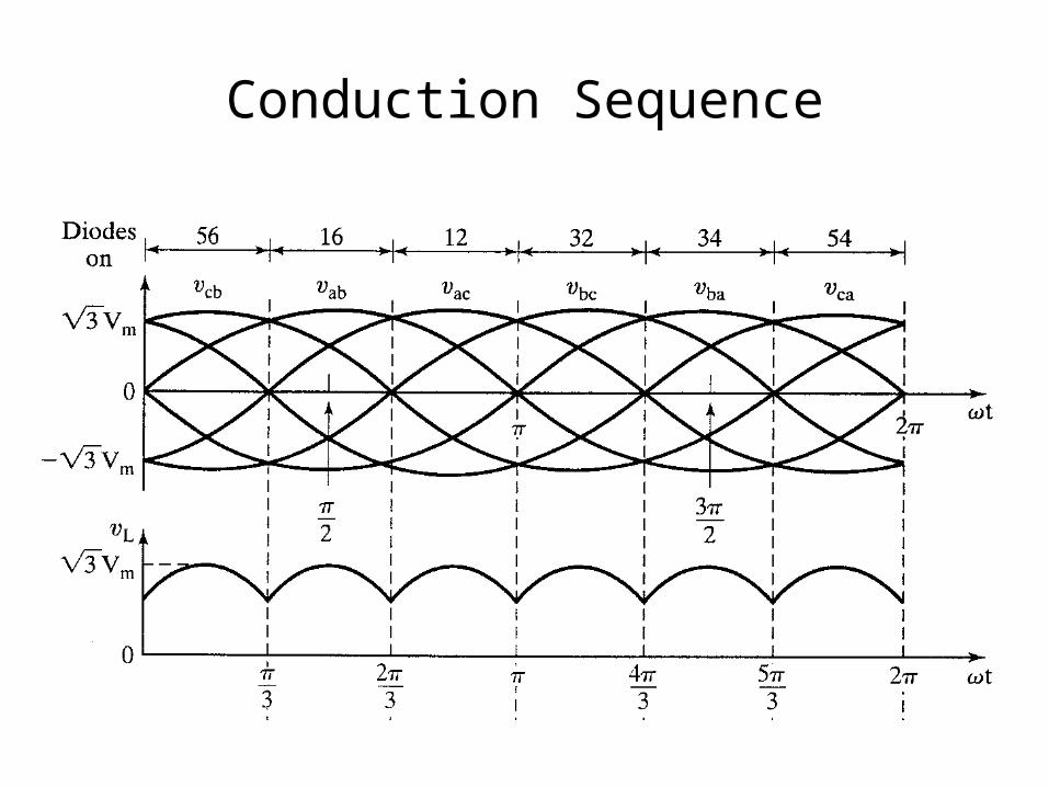
Conduction Sequence
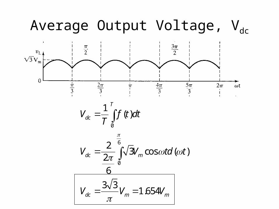
Average Output Voltage, Vdc
0
6
0
1( )
23 cos ( )
26
3 31.654
T
dc
dc m
dc m m
V f t dtT
V V td t
V V V

rms Output Voltage1
2
62 2
0
1
2
23 cos ( )
26
3 9 3
2 4
1.6554
rms m
rms m
rms m
V V td t
V V
V V
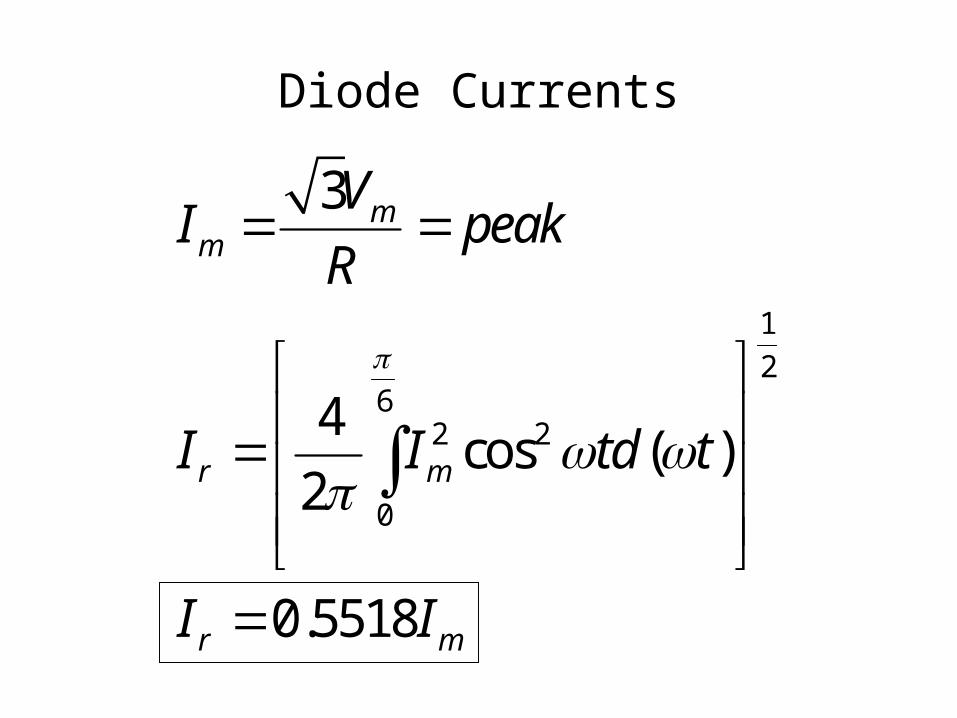
Diode Currents
1
26
2 2
0
3
4cos ( )
2
0.5518
mm
r m
r m
VI peak
R
I I td t
I I
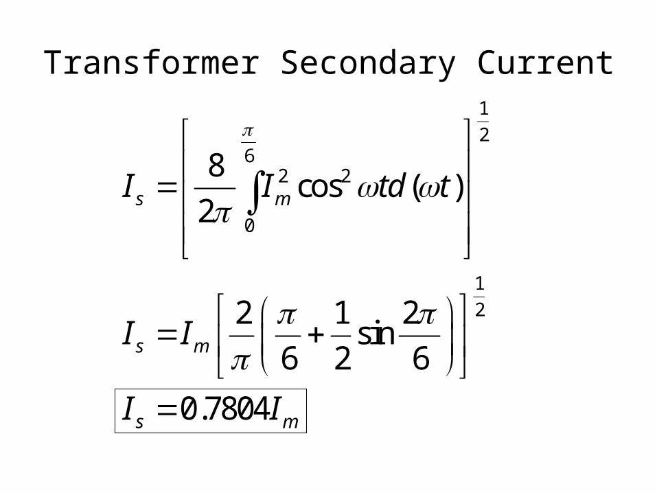
Transformer Secondary Current1
26
2 2
0
1
2
8cos ( )
2
2 1 2sin
6 2 6
0.7804
s m
s m
s m
I I td t
I I
I I
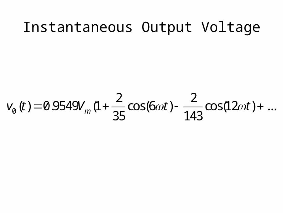
Instantaneous Output Voltage
0
2 2( ) 0.9549 (1 cos(6 ) cos(12 ) ...
35 143mv t V t t