Embed Size (px)
Citation preview
Lecture Notes Three-Phase Synchronous Machines Saad M. Alwash
٢٠١٥ ١الصفحة
Phase Synchronous Machines-Three The synchronous machine can be used to operate as:
1. Synchronous motors 2. Synchronous generators (Alternator) Synchronous generator is also referred to as alternator since it
generates alternating voltage. Synchronous machine is designed to be operating at
synchronous speed, nS.
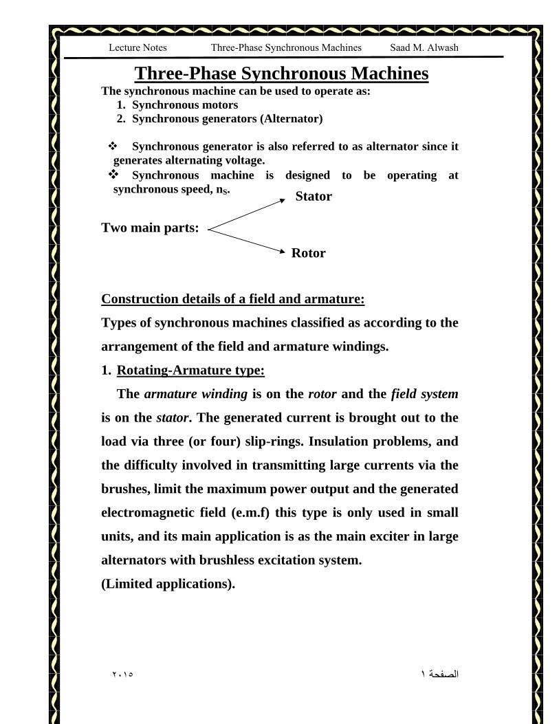
Two main parts:
Construction details of a field and armature:
Types of synchronous machines classified as according to the
arrangement of the field and armature windings.
1. Rotating-Armature type:
The armature winding is on the rotor and the field system
is on the stator. The generated current is brought out to the
load via three (or four) slip-rings. Insulation problems, and
the difficulty involved in transmitting large currents via the
brushes, limit the maximum power output and the generated
electromagnetic field (e.m.f) this type is only used in small
units, and its main application is as the main exciter in large
alternators with brushless excitation system.
(Limited applications).
Stator
Rotor
Lecture Notes Three-Phase Synchronous Machines Saad M. Alwash
٢٠١٥ ٢الصفحة
2. Rotating-field type
The armature winding is on the stator and the field system
is on the rotor. Field current is supplied from the exciter via
two slip-rings, while the armature current is directly
supplied to the load. This type is employed universally since
very high power can be delivered. (Used in commercial
application).
The part of the machine in which voltage is induced
is called armature.
Advantages of rotating field and stationary armature system
1. Ease of construction for large three-phase SYG. Since the armature winding is more complex than the field winding.
2. Number of slip-rings required only two slip-rings. 3. It is easier to insulate the armature coils from the core
if the windings are placed on the stator instead of on the rotor.
4. The weight of the field system placed on the rotor is comparatively much lower than the armature windings placed on stator.
5. Improved ventilation arrangement air-cooling or/and hydrogen cooling for large gen. can easily be made on a stationary armature
Construction of synchronous generators: The armature winding, usually on the stator and the
field windings usually on the rotor is d.c excited. 1- Stator (armature): Three-phase windings connected on
star or delta. 2- Rotor (field)
The types of synchronous machines classified as according to the shape of the field.
Lecture Notes Three-Phase Synchronous Machines Saad M. Alwash
٢٠١٥ ٣الصفحة
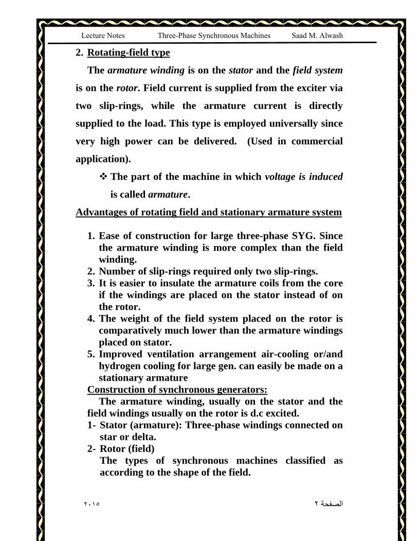
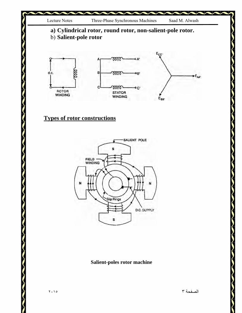
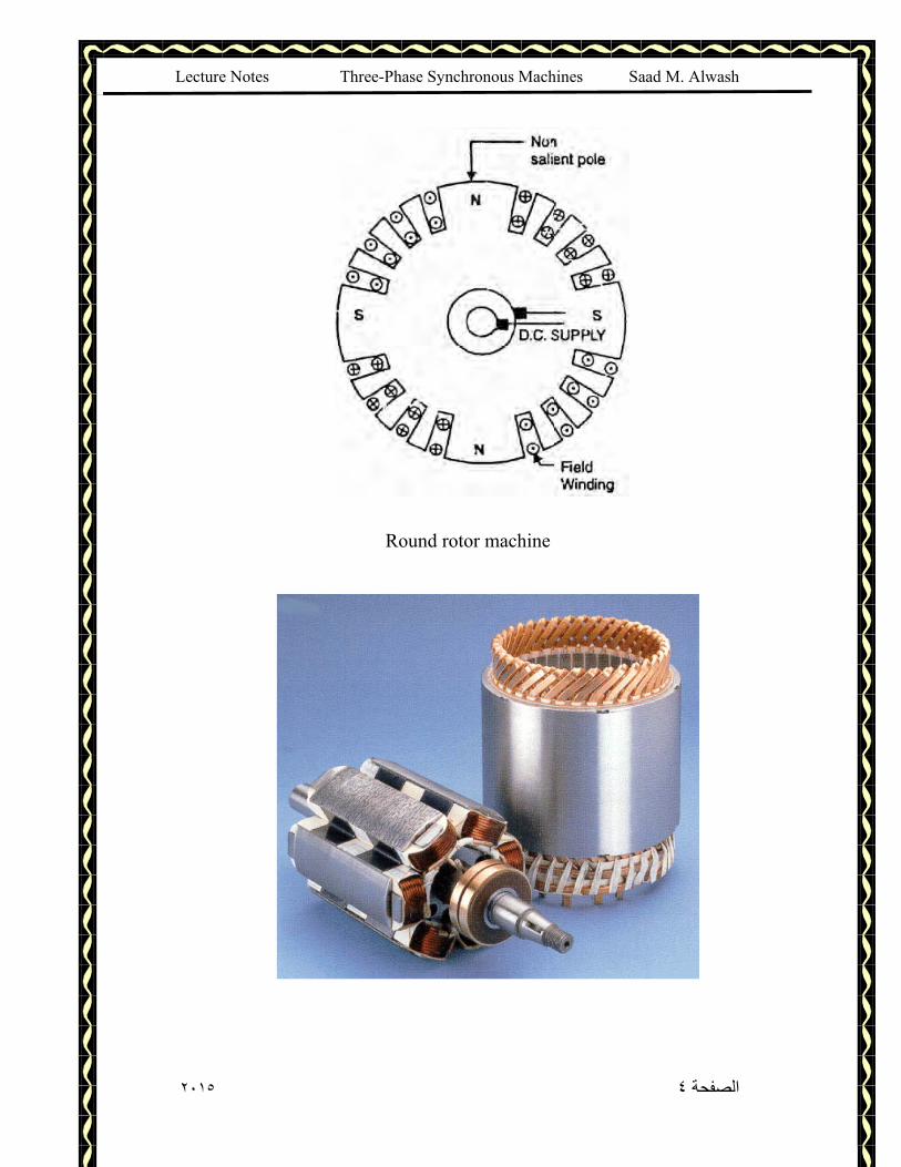
a) Cylindrical rotor, round rotor, non-salient-pole rotor. b) Salient-pole rotor
Types of rotor constructions
Salient-poles rotor machine
Lecture Notes Three-Phase Synchronous Machines Saad M. Alwash
٢٠١٥ ٤الصفحة
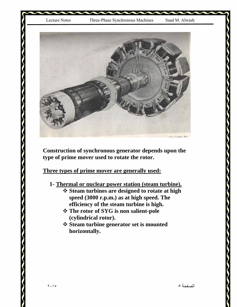
Round rotor machine
Lecture Notes Three-Phase Synchronous Machines Saad M. Alwash
٢٠١٥ ٥الصفحة
Construction of synchronous generator depends upon the type of prime mover used to rotate the rotor. Three types of prime mover are generally used:
1- Thermal or nuclear power station (steam turbine). Steam turbines are designed to rotate at high
speed (3000 r.p.m.) as at high speed. The efficiency of the steam turbine is high.
The rotor of SYG is non salient-pole (cylindrical rotor).
Steam turbine generator set is mounted horizontally.

Lecture Notes Three-Phase Synchronous Machines Saad M. Alwash
٢٠١٥ ٦الصفحة
Lecture Notes Three-Phase Synchronous Machines Saad M. Alwash
٢٠١٥ ٧الصفحة
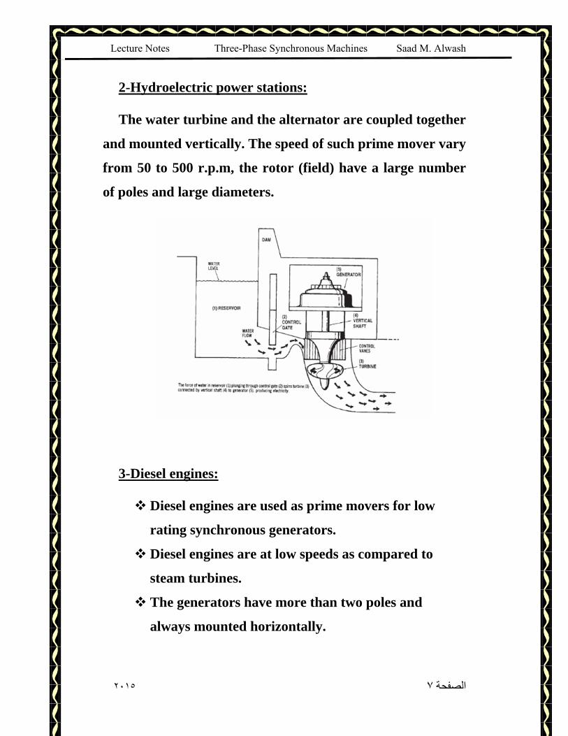
2-Hydroelectric power stations:
The water turbine and the alternator are coupled together
and mounted vertically. The speed of such prime mover vary
from 50 to 500 r.p.m, the rotor (field) have a large number
of poles and large diameters.
3-Diesel engines:
Diesel engines are used as prime movers for low
rating synchronous generators.
Diesel engines are at low speeds as compared to
steam turbines.
The generators have more than two poles and
always mounted horizontally.
Lecture Notes Three-Phase Synchronous Machines Saad M. Alwash
٢٠١٥ ٨الصفحة
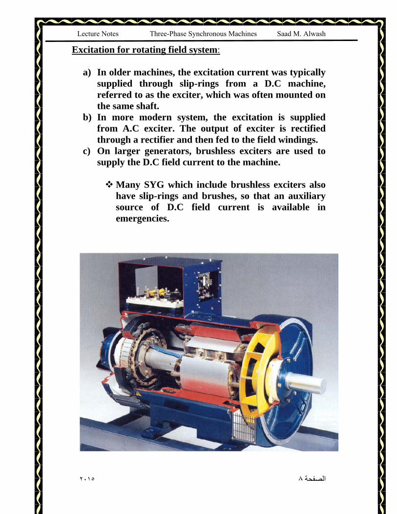
Excitation for rotating field system:
a) In older machines, the excitation current was typically supplied through slip-rings from a D.C machine, referred to as the exciter, which was often mounted on the same shaft.
b) In more modern system, the excitation is supplied from A.C exciter. The output of exciter is rectified through a rectifier and then fed to the field windings.
c) On larger generators, brushless exciters are used to supply the D.C field current to the machine.
Many SYG which include brushless exciters also
have slip-rings and brushes, so that an auxiliary source of D.C field current is available in emergencies.
Lecture Notes Three-Phase Synchronous Machines Saad M. Alwash
٢٠١٥ ٩الصفحة
According to the shape of the field, the synchronous machines may be classified as: 1. Non-salient pole (operate at high speeds usually two poles). Why non-salient pole machine usually has small diameter-to-length ratio? In order to avoid excessive a windage loss and excessive mechanical stress on the rotor due to the large centrifugal forces and also avoid noise. 2. Salient pole (operate at low speeds). Why salient pole machine usually has a large diameter-to-length ratio? Since a frequency of 50 Hz is required, we must use a large number of poles on rotor of slow-speed alternators. Magnitude of induced e.m.f in each phase: The magnitude of the voltage induced in each phase depends upon the rotor flux, the number and position of conductors in the phase and the speed of rotation the rotor.
nKEg ..
Where: K: Is a constant representing the construction of the machine. n: Mechanical speed (r.p.m). φ: Flux it depends on the current flowing in the rotor field circuit. Frequency: The frequency of induced e.m.f in the armature conductors depends upon speed and the number of poles.
60
. PS Pnf
Where: f: Frequency of e.m.f in Hz. ns: Rotor speed in (r.p.m), synchronous speed. PP: Number of rotor pair pole.
Lecture Notes Three-Phase Synchronous Machines Saad M. Alwash
٢٠١٥ ١٠الصفحة
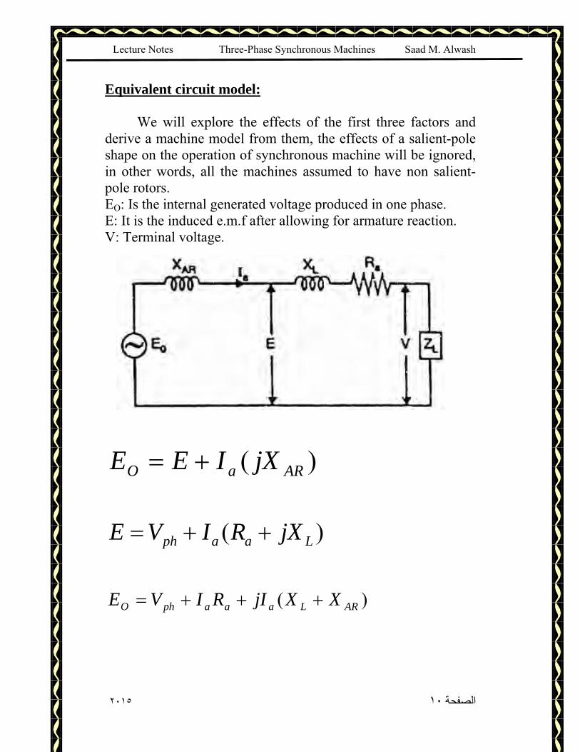
Equivalent circuit model:
We will explore the effects of the first three factors and derive a machine model from them, the effects of a salient-pole shape on the operation of synchronous machine will be ignored, in other words, all the machines assumed to have non salient- pole rotors. EO: Is the internal generated voltage produced in one phase. E: It is the induced e.m.f after allowing for armature reaction. V: Terminal voltage.
)( ARaO jXIEE
)( Laaph jXRIVE
)( ARLaaaphO XXjIRIVE
Lecture Notes Three-Phase Synchronous Machines Saad M. Alwash
٢٠١٥ ١١الصفحة
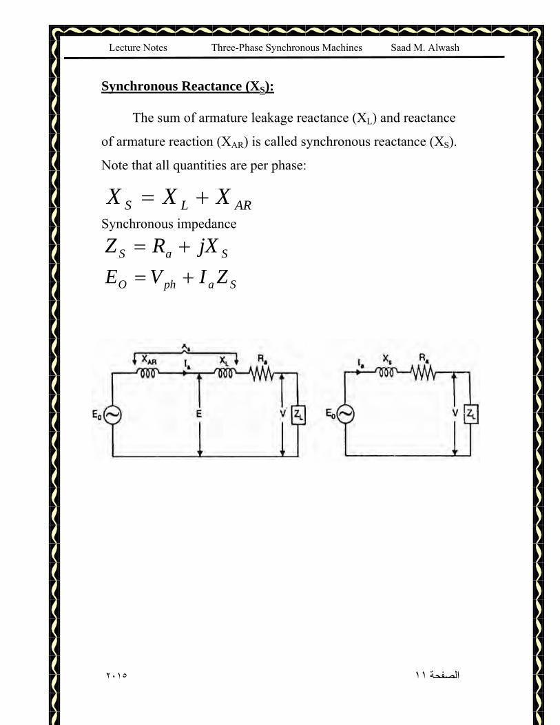
Synchronous Reactance (XS):
The sum of armature leakage reactance (XL) and reactance
of armature reaction (XAR) is called synchronous reactance (XS).
Note that all quantities are per phase:
ARLS XXX
Synchronous impedance
SaS jXRZ
SaphO ZIVE

Lecture Notes Three-Phase Synchronous Machines Saad M. Alwash
٢٠١٥ ١٢الصفحة
Phasor Diagram of a Synchronous Generator When the synchronous generator non-salient pole is supplying a load; at unity power factor (purely resistive load) Load at lagging P.F
EO
Ia
Ra
VF
Ia V IaRa
jXSIa
EO
Ia
IaRa
j XSIS
EO
Lecture Notes Three-Phase Synchronous Machines Saad M. Alwash
٢٠١٥ ١٣الصفحة
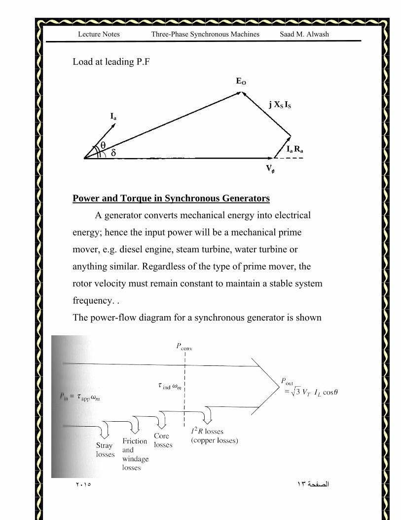
Load at leading P.F Power and Torque in Synchronous Generators
A generator converts mechanical energy into electrical
energy; hence the input power will be a mechanical prime
mover, e.g. diesel engine, steam turbine, water turbine or
anything similar. Regardless of the type of prime mover, the
rotor velocity must remain constant to maintain a stable system
frequency. .
The power-flow diagram for a synchronous generator is shown
Ia
EO
j XS IS
Ia Ra
Lecture Notes Three-Phase Synchronous Machines Saad M. Alwash
٢٠١٥ ١٤الصفحة
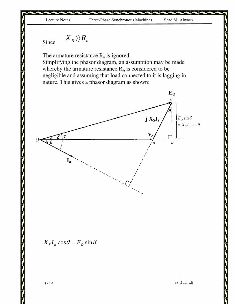
Since aS RX
The armature resistance Ra is ignored, Simplifying the phasor diagram, an assumption may be made whereby the armature resistance RA is considered to be negligible and assuming that load connected to it is lagging in nature. This gives a phasor diagram as shown:
sincos OaS EIX
EO
Ia
j XSIa
cos
sin
aS
O
IX
E
Lecture Notes Three-Phase Synchronous Machines Saad M. Alwash
٢٠١٥ ١٥الصفحة
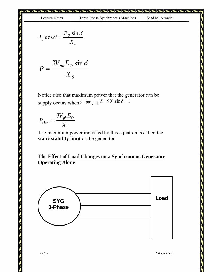
S
Oa X
EI
sincos
S
Oph
X
EVP
sin3
Notice also that maximum power that the generator can be
supply occurs when 90 , at 1sin,90
S
OphMax X
EVP
3.
The maximum power indicated by this equation is called the static stability limit of the generator. The Effect of Load Changes on a Synchronous Generator Operating Alone
SYG 3-Phase
Load
Lecture Notes Three-Phase Synchronous Machines Saad M. Alwash
٢٠١٥ ١٦الصفحة
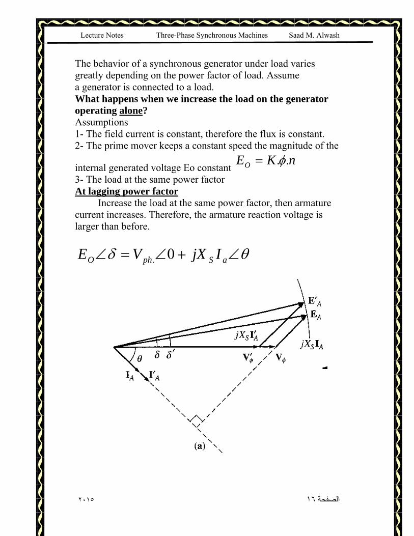
The behavior of a synchronous generator under load varies greatly depending on the power factor of load. Assume a generator is connected to a load. What happens when we increase the load on the generator operating alone? Assumptions 1- The field current is constant, therefore the flux is constant. 2- The prime mover keeps a constant speed the magnitude of the
internal generated voltage Eo constant nKEO ..
3- The load at the same power factor At lagging power factor
Increase the load at the same power factor, then armature current increases. Therefore, the armature reaction voltage is larger than before.
aSphO IjXVE 0.
Lecture Notes Three-Phase Synchronous Machines Saad M. Alwash
٢٠١٥ ١٧الصفحة
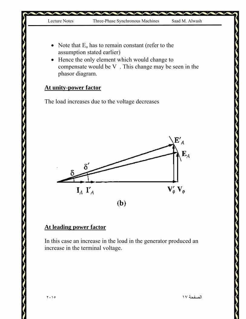
Note that Eo has to remain constant (refer to the assumption stated earlier)
Hence the only element which would change to compensate would be V�. This change may be seen in the phasor diagram.
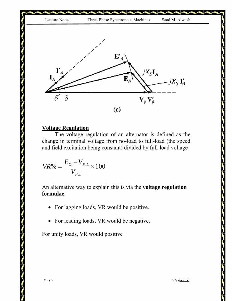
At unity-power factor The load increases due to the voltage decreases At leading power factor In this case an increase in the load in the generator produced an increase in the terminal voltage.
Lecture Notes Three-Phase Synchronous Machines Saad M. Alwash
٢٠١٥ ١٨الصفحة
Voltage Regulation
The voltage regulation of an alternator is defined as the change in terminal voltage from no-load to full-load (the speed and field excitation being constant) divided by full-load voltage
100%.
.
LF
LFO
V
VEVR
An alternative way to explain this is via the voltage regulation formulae.
For lagging loads, VR would be positive.
For leading loads, VR would be negative. For unity loads, VR would positive
Lecture Notes Three-Phase Synchronous Machines Saad M. Alwash
٢٠١٥ ١٩الصفحة
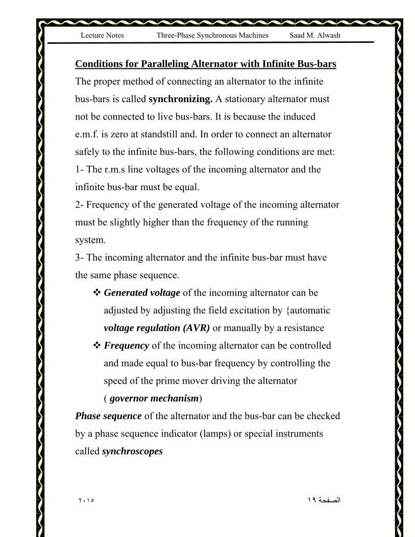
Conditions for Paralleling Alternator with Infinite Bus-bars
The proper method of connecting an alternator to the infinite
bus-bars is called synchronizing. A stationary alternator must
not be connected to live bus-bars. It is because the induced
e.m.f. is zero at standstill and. In order to connect an alternator
safely to the infinite bus-bars, the following conditions are met:
1- The r.m.s line voltages of the incoming alternator and the
infinite bus-bar must be equal.
2- Frequency of the generated voltage of the incoming alternator
must be slightly higher than the frequency of the running
system.
3- The incoming alternator and the infinite bus-bar must have
the same phase sequence.
Generated voltage of the incoming alternator can be
adjusted by adjusting the field excitation by {automatic
voltage regulation (AVR) or manually by a resistance
Frequency of the incoming alternator can be controlled
and made equal to bus-bar frequency by controlling the
speed of the prime mover driving the alternator
( governor mechanism)
Phase sequence of the alternator and the bus-bar can be checked
by a phase sequence indicator (lamps) or special instruments
called synchroscopes
Lecture Notes Three-Phase Synchronous Machines Saad M. Alwash
٢٠١٥ ٢٠الصفحة
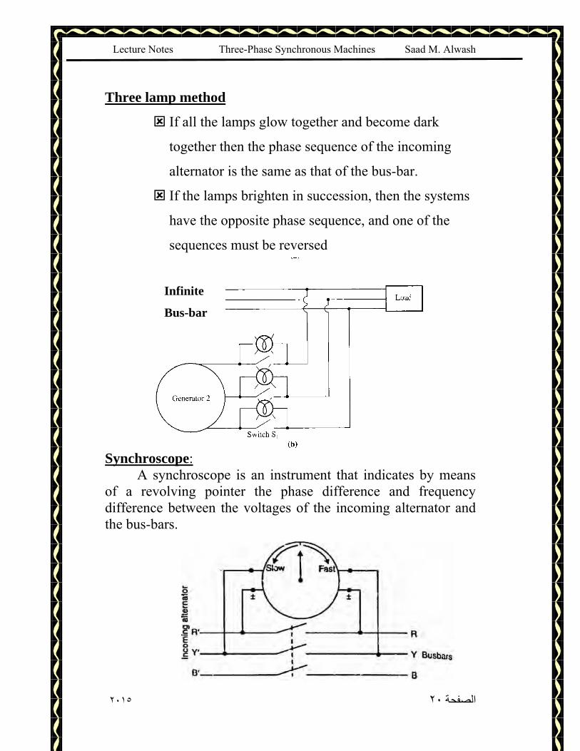
Three lamp method
If all the lamps glow together and become dark
together then the phase sequence of the incoming
alternator is the same as that of the bus-bar.
If the lamps brighten in succession, then the systems
have the opposite phase sequence, and one of the
sequences must be reversed
Synchroscope:
A synchroscope is an instrument that indicates by means of a revolving pointer the phase difference and frequency difference between the voltages of the incoming alternator and the bus-bars.
Infinite
Bus-bar
Lecture Notes Three-Phase Synchronous Machines Saad M. Alwash
٢٠١٥ ٢١الصفحة
In large generators belonging to power system, this whole
process of paralleling a new generator to the line is
automated, and a computer does this job.
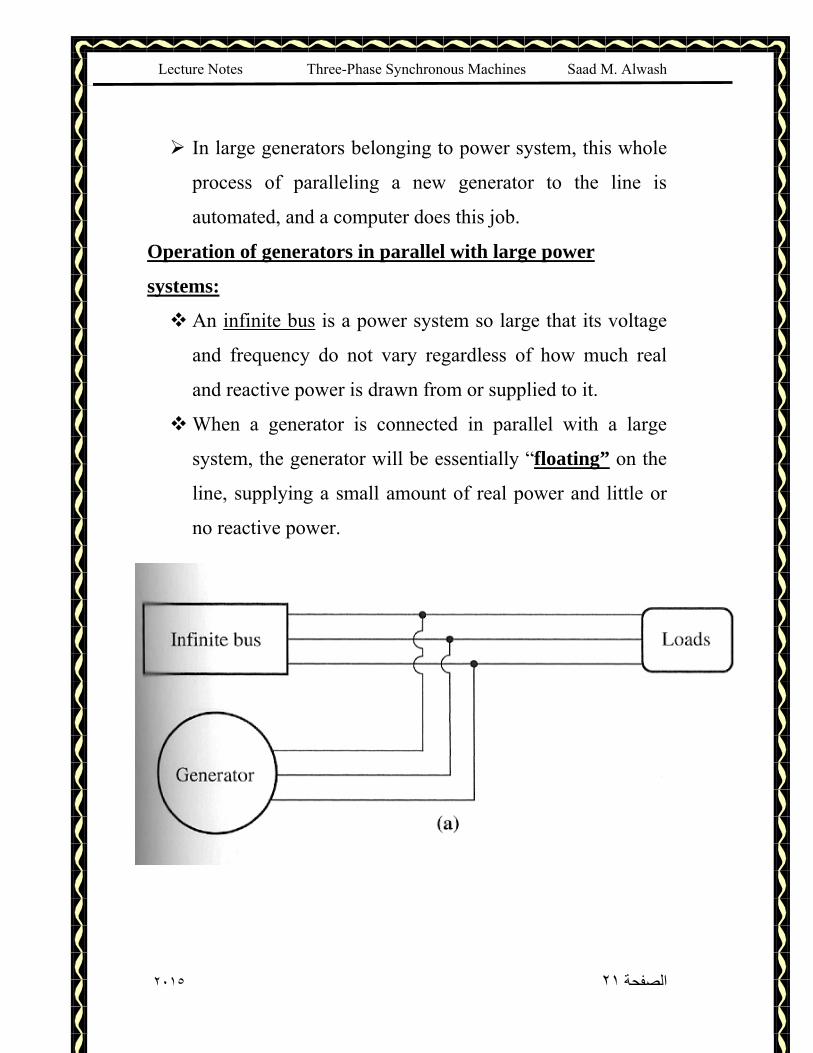
Operation of generators in parallel with large power
systems:
An infinite bus is a power system so large that its voltage
and frequency do not vary regardless of how much real
and reactive power is drawn from or supplied to it.
When a generator is connected in parallel with a large
system, the generator will be essentially “floating” on the
line, supplying a small amount of real power and little or
no reactive power.
Lecture Notes Three-Phase Synchronous Machines Saad M. Alwash
٢٠١٥ ٢٢الصفحة
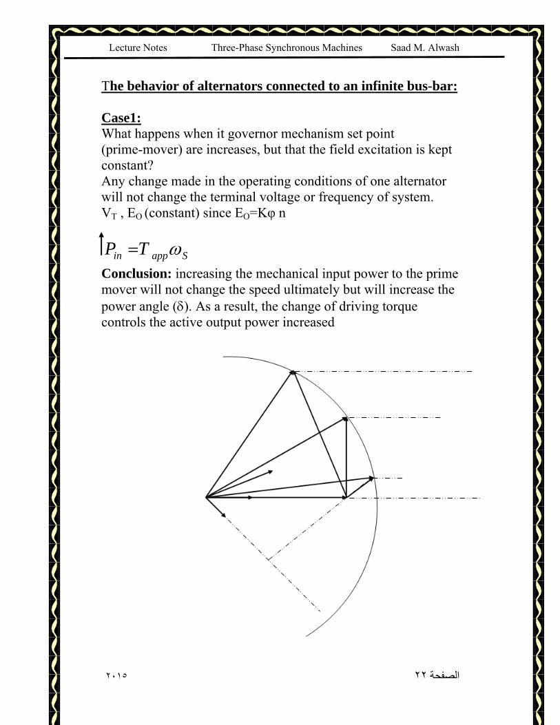
The behavior of alternators connected to an infinite bus-bar: Case1: What happens when it governor mechanism set point (prime-mover) are increases, but that the field excitation is kept constant? Any change made in the operating conditions of one alternator will not change the terminal voltage or frequency of system. VT , EO (constant) since EO=Kφ n
Sappin TP
Conclusion: increasing the mechanical input power to the prime mover will not change the speed ultimately but will increase the power angle (). As a result, the change of driving torque controls the active output power increased
Lecture Notes Three-Phase Synchronous Machines Saad M. Alwash
٢٠١٥ ٢٣الصفحة
After the real power of the generator has been adjusted to the
desired value, the phasor diagram of generator look like at this
time the generator is actually operating a slightly leading power
factor, supplying negative reactive power. How cans the
generator be adjusted so that it will supply some reactive power
to the system?
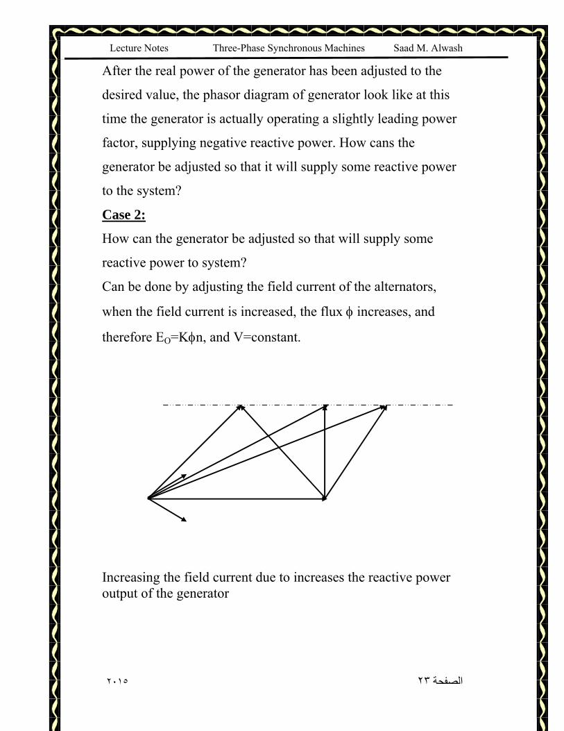
Case 2:
How can the generator be adjusted so that will supply some
reactive power to system?
Can be done by adjusting the field current of the alternators,
when the field current is increased, the flux increases, and
therefore EO=Kn, and V=constant.
Increasing the field current due to increases the reactive power output of the generator
Lecture Notes Three-Phase Synchronous Machines Saad M. Alwash
٢٠١٥ ٢٤الصفحة
Summary: When a generator is operating by itself supplying the system
loads (alone):
1. The real and reactive power supplied by the generator will be
the amount demanded by the attached load.
2. The governor set points of the generator will control the
operating frequency of the power system.
3. The field current set points control the terminal voltage of the
power system.
When a generator is operating in parallel with an infinite
bus-bar:
1. The frequency and terminal voltage of the generator are
controlled by the system to which it is connected.
2. The governor set points of the generator control the real
power supplied by the generator to system.
3. The field current in the generator controls the reactive power
supplied by the generator to the system.
Advantages of Parallel Operation of Alternators
The following are the advantages of operating alternators in
parallel:
1. Continuity of service. The continuity of service is one of
the important requirements of any electrical apparatus. If
one alternator fails, the continuity of supply can be
maintained.
Lecture Notes Three-Phase Synchronous Machines Saad M. Alwash
٢٠١٥ ٢٥الصفحة
through the other healthy units. This will ensure uninterrupted
supply to the consumers.
2. Increased Efficiency: The load on the power system varies
during the whole day; being minimum during die late night
hours. Since alternators operate most efficiently when delivering
full-load, units can be added or put off depending upon the load
requirement. This permits the efficient operation of the power
system.
3. Maintenance and repair can be done without power
disruption. It is often desirable to carry out routine maintenance
and repair of one or more units. For this purpose, the desired
Unit/units can be shut down and the continuity of supply is
maintained through the other units
4. Load growth. The load demand is increasing due to the
increasing use of electrical energy. The load growth can be met
by adding more units without disturbing the original installation.