Embed Size (px)
Citation preview
INV
ER
TE
RS
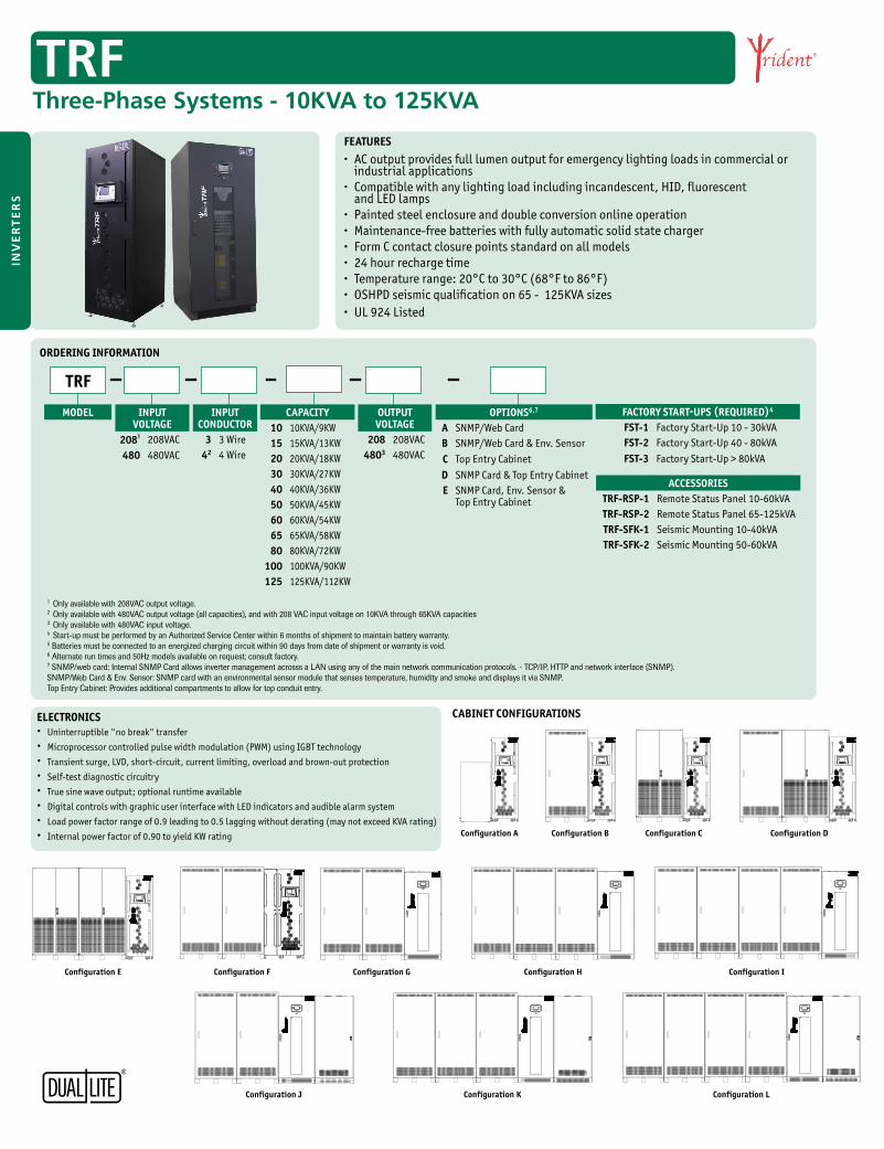
• AC output provides full lumen output for emergency lighting loads in commercial or industrial applications
• Compatible with any lighting load including incandescent, HID, fluorescent and LED lamps
• Painted steel enclosure and double conversion online operation• Maintenance-free batteries with fully automatic solid state charger• Form C contact closure points standard on all models• 24 hour recharge time• Temperature range: 20°C to 30°C (68°F to 86°F)• OSHPD seismic qualification on 65 - 125KVA sizes• UL 924 Listed
MODEL
TRF
OUTPUT VOLTAGE
208 208VAC4803 480VAC
INPUTVOLTAGE
208¹ 208VAC480 480VAC
INPUT CONDUCTOR
3 3 Wire42 4 Wire
CAPACITY10 10KVA/9KW15 15KVA/13KW20 20KVA/18KW30 30KVA/27KW40 40KVA/36KW50 50KVA/45KW60 60KVA/54KW65 65KVA/58KW80 80KVA/72KW
100 100KVA/90KW125 125KVA/112KW
OPTIONS6,7
A SNMP/Web CardB SNMP/Web Card & Env. SensorC Top Entry CabinetD SNMP Card & Top Entry CabinetE SNMP Card, Env. Sensor &
Top Entry Cabinet
FACTORY START-UPS (REQUIRED)4
FST-1 Factory Start-Up 10 - 30kVAFST-2 Factory Start-Up 40 - 80kVAFST-3 Factory Start-Up > 80kVA
ACCESSORIESTRF-RSP-1 Remote Status Panel 10-60kVATRF-RSP-2 Remote Status Panel 65-125kVATRF-SFK-1 Seismic Mounting 10-40kVATRF-SFK-2 Seismic Mounting 50-60kVA
1 Only available with 208VAC output voltage.2 Only available with 480VAC output voltage (all capacities), and with 208 VAC input voltage on 10KVA through 65KVA capacities3 Only available with 480VAC input voltage.4 Start-up must be performed by an Authorized Service Center within 6 months of shipment to maintain battery warranty.5 Batteries must be connected to an energized charging circuit within 90 days from date of shipment or warranty is void.6 Alternate run times and 50Hz models available on request; consult factory.7 SNMP/web card: Internal SNMP Card allows inverter management acrosss a LAN using any of the main network communication protocols. - TCP/IP, HTTP and network interface (SNMP). SNMP/Web Card & Env. Sensor: SNMP card with an environmental sensor module that senses temperature, humidity and smoke and displays it via SNMP. Top Entry Cabinet: Provides additional compartments to allow for top conduit entry.
FEATURES
TRFThree-Phase Systems - 10KVA to 125KVA
ELECTRONICS• Uninterruptible "no break" transfer• Microprocessor controlled pulse width modulation (PWM) using IGBT technology• Transient surge, LVD, short-circuit, current limiting, overload and brown-out protection• Self-test diagnostic circuitry• True sine wave output; optional runtime available• Digital controls with graphic user interface with LED indicators and audible alarm system• Load power factor range of 0.9 leading to 0.5 lagging without derating (may not exceed KVA rating)• Internal power factor of 0.90 to yield KW rating
ORDERING INFORMATION
CABINET CONFIGURATIONS
Cabinet Con�gurations
Con�guration A Con�guration B Con�guration C Con�guration D Con�guration E Con�guration F
Con�guration G Con�guration H Con�guration I
Con�guration J Con�guration K Con�guration L
Cabinet Con�gurations
Con�guration A Con�guration B Con�guration C Con�guration D Con�guration E Con�guration F
Con�guration G Con�guration H Con�guration I
Con�guration J Con�guration K Con�guration L
Cabinet Con�gurations
Con�guration A Con�guration B Con�guration C Con�guration D Con�guration E Con�guration F
Con�guration G Con�guration H Con�guration I
Con�guration J Con�guration K Con�guration L
Cabinet Con�gurations
Con�guration A Con�guration B Con�guration C Con�guration D Con�guration E Con�guration F
Con�guration G Con�guration H Con�guration I
Con�guration J Con�guration K Con�guration L
Cabinet Con�gurations
Con�guration A Con�guration B Con�guration C Con�guration D Con�guration E Con�guration F
Con�guration G Con�guration H Con�guration I
Con�guration J Con�guration K Con�guration L
Configuration A Configuration B Configuration C Configuration D
Configuration E Configuration F Configuration G Configuration H Configuration I
Configuration J Configuration K Configuration L
INV
ER
TE
RS
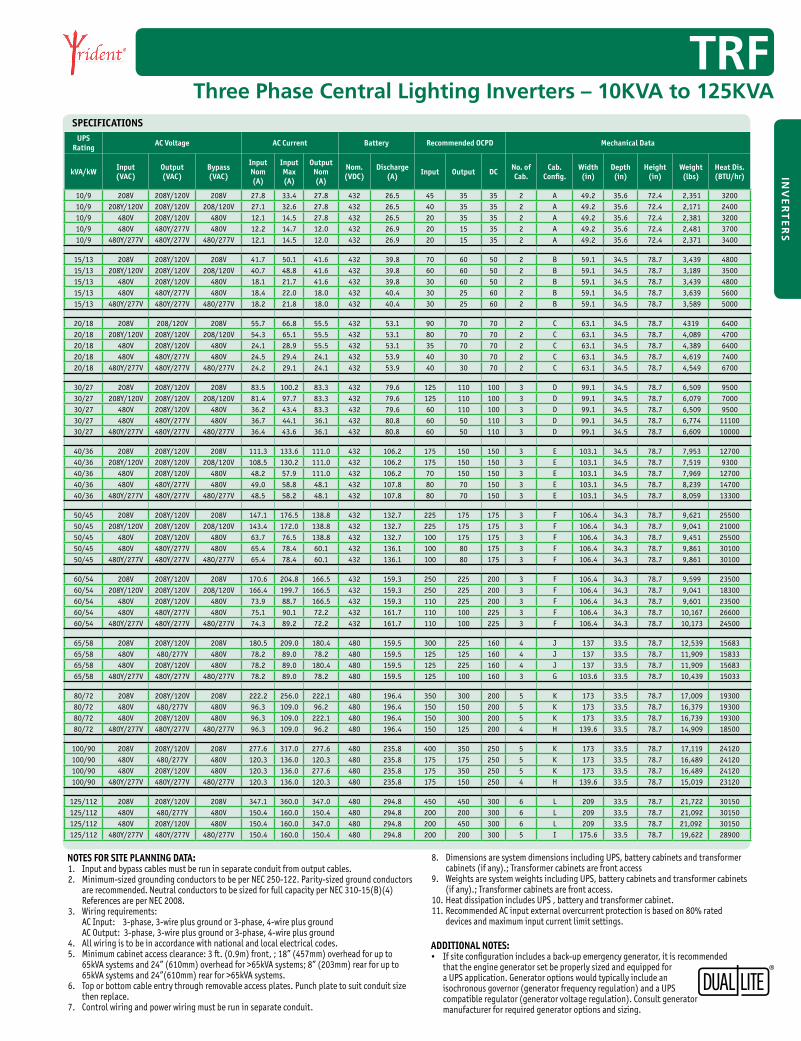
UPS Rating AC Voltage AC Current Battery Recommended OCPD Mechanical Data
kVA/kW Input (VAC)
Output (VAC)
Bypass(VAC)
Input Nom (A)
Input Max (A)
Output Nom (A)
Nom. (VDC)
Discharge(A) Input Output DC No. of
Cab.Cab.
Config.Width(in)
Depth(in)
Height(in)
Weight(lbs)
Heat Dis.(BTU/hr)
10/9 208V 208Y/120V 208V 27.8 33.4 27.8 432 26.5 45 35 35 2 A 49.2 35.6 72.4 2,351 320010/9 208Y/120V 208Y/120V 208/120V 27.1 32.6 27.8 432 26.5 40 35 35 2 A 49.2 35.6 72.4 2,171 240010/9 480V 208Y/120V 480V 12.1 14.5 27.8 432 26.5 20 35 35 2 A 49.2 35.6 72.4 2,381 320010/9 480V 480Y/277V 480V 12.2 14.7 12.0 432 26.9 20 15 35 2 A 49.2 35.6 72.4 2,481 370010/9 480Y/277V 480Y/277V 480/277V 12.1 14.5 12.0 432 26.9 20 15 35 2 A 49.2 35.6 72.4 2,371 3400
15/13 208V 208Y/120V 208V 41.7 50.1 41.6 432 39.8 70 60 50 2 B 59.1 34.5 78.7 3,439 480015/13 208Y/120V 208Y/120V 208/120V 40.7 48.8 41.6 432 39.8 60 60 50 2 B 59.1 34.5 78.7 3,189 350015/13 480V 208Y/120V 480V 18.1 21.7 41.6 432 39.8 30 60 50 2 B 59.1 34.5 78.7 3,439 480015/13 480V 480Y/277V 480V 18.4 22.0 18.0 432 40.4 30 25 60 2 B 59.1 34.5 78.7 3,639 560015/13 480Y/277V 480Y/277V 480/277V 18.2 21.8 18.0 432 40.4 30 25 60 2 B 59.1 34.5 78.7 3,589 5000
20/18 208V 208/120V 208V 55.7 66.8 55.5 432 53.1 90 70 70 2 C 63.1 34.5 78.7 4319 640020/18 208Y/120V 208Y/120V 208/120V 54.3 65.1 55.5 432 53.1 80 70 70 2 C 63.1 34.5 78.7 4,089 470020/18 480V 208Y/120V 480V 24.1 28.9 55.5 432 53.1 35 70 70 2 C 63.1 34.5 78.7 4,389 640020/18 480V 480Y/277V 480V 24.5 29.4 24.1 432 53.9 40 30 70 2 C 63.1 34.5 78.7 4,619 740020/18 480Y/277V 480Y/277V 480/277V 24.2 29.1 24.1 432 53.9 40 30 70 2 C 63.1 34.5 78.7 4,549 6700
30/27 208V 208Y/120V 208V 83.5 100.2 83.3 432 79.6 125 110 100 3 D 99.1 34.5 78.7 6,509 950030/27 208Y/120V 208Y/120V 208/120V 81.4 97.7 83.3 432 79.6 125 110 100 3 D 99.1 34.5 78.7 6,079 700030/27 480V 208Y/120V 480V 36.2 43.4 83.3 432 79.6 60 110 100 3 D 99.1 34.5 78.7 6,509 950030/27 480V 480Y/277V 480V 36.7 44.1 36.1 432 80.8 60 50 110 3 D 99.1 34.5 78.7 6,774 1110030/27 480Y/277V 480Y/277V 480/277V 36.4 43.6 36.1 432 80.8 60 50 110 3 D 99.1 34.5 78.7 6,609 10000
40/36 208V 208Y/120V 208V 111.3 133.6 111.0 432 106.2 175 150 150 3 E 103.1 34.5 78.7 7,953 1270040/36 208Y/120V 208Y/120V 208/120V 108.5 130.2 111.0 432 106.2 175 150 150 3 E 103.1 34.5 78.7 7,519 930040/36 480V 208Y/120V 480V 48.2 57.9 111.0 432 106.2 70 150 150 3 E 103.1 34.5 78.7 7,969 1270040/36 480V 480Y/277V 480V 49.0 58.8 48.1 432 107.8 80 70 150 3 E 103.1 34.5 78.7 8,239 1470040/36 480Y/277V 480Y/277V 480/277V 48.5 58.2 48.1 432 107.8 80 70 150 3 E 103.1 34.5 78.7 8,059 13300
50/45 208V 208Y/120V 208V 147.1 176.5 138.8 432 132.7 225 175 175 3 F 106.4 34.3 78.7 9,621 2550050/45 208Y/120V 208Y/120V 208/120V 143.4 172.0 138.8 432 132.7 225 175 175 3 F 106.4 34.3 78.7 9,041 2100050/45 480V 208Y/120V 480V 63.7 76.5 138.8 432 132.7 100 175 175 3 F 106.4 34.3 78.7 9,451 2550050/45 480V 480Y/277V 480V 65.4 78.4 60.1 432 136.1 100 80 175 3 F 106.4 34.3 78.7 9,861 3010050/45 480Y/277V 480Y/277V 480/277V 65.4 78.4 60.1 432 136.1 100 80 175 3 F 106.4 34.3 78.7 9,861 30100
60/54 208V 208Y/120V 208V 170.6 204.8 166.5 432 159.3 250 225 200 3 F 106.4 34.3 78.7 9,599 2350060/54 208Y/120V 208Y/120V 208/120V 166.4 199.7 166.5 432 159.3 250 225 200 3 F 106.4 34.3 78.7 9,041 1830060/54 480V 208Y/120V 480V 73.9 88.7 166.5 432 159.3 110 225 200 3 F 106.4 34.3 78.7 9,601 2350060/54 480V 480Y/277V 480V 75.1 90.1 72.2 432 161.7 110 100 225 3 F 106.4 34.3 78.7 10,167 2660060/54 480Y/277V 480Y/277V 480/277V 74.3 89.2 72.2 432 161.7 110 100 225 3 F 106.4 34.3 78.7 10,173 24500
65/58 208V 208Y/120V 208V 180.5 209.0 180.4 480 159.5 300 225 160 4 J 137 33.5 78.7 12,539 1568365/58 480V 480/277V 480V 78.2 89.0 78.2 480 159.5 125 125 160 4 J 137 33.5 78.7 11,909 1583365/58 480V 208Y/120V 480V 78.2 89.0 180.4 480 159.5 125 225 160 4 J 137 33.5 78.7 11,909 1568365/58 480Y/277V 480Y/277V 480/277V 78.2 89.0 78.2 480 159.5 125 100 160 3 G 103.6 33.5 78.7 10,439 15033
80/72 208V 208Y/120V 208V 222.2 256.0 222.1 480 196.4 350 300 200 5 K 173 33.5 78.7 17,009 1930080/72 480V 480/277V 480V 96.3 109.0 96.2 480 196.4 150 150 200 5 K 173 33.5 78.7 16,379 1930080/72 480V 208Y/120V 480V 96.3 109.0 222.1 480 196.4 150 300 200 5 K 173 33.5 78.7 16,739 1930080/72 480Y/277V 480Y/277V 480/277V 96.3 109.0 96.2 480 196.4 150 125 200 4 H 139.6 33.5 78.7 14,909 18500
100/90 208V 208Y/120V 208V 277.6 317.0 277.6 480 235.8 400 350 250 5 K 173 33.5 78.7 17,119 24120100/90 480V 480/277V 480V 120.3 136.0 120.3 480 235.8 175 175 250 5 K 173 33.5 78.7 16,489 24120100/90 480V 208Y/120V 480V 120.3 136.0 277.6 480 235.8 175 350 250 5 K 173 33.5 78.7 16,489 24120100/90 480Y/277V 480Y/277V 480/277V 120.3 136.0 120.3 480 235.8 175 150 250 4 H 139.6 33.5 78.7 15,019 23120
125/112 208V 208Y/120V 208V 347.1 360.0 347.0 480 294.8 450 450 300 6 L 209 33.5 78.7 21,722 30150125/112 480V 480/277V 480V 150.4 160.0 150.4 480 294.8 200 200 300 6 L 209 33.5 78.7 21,092 30150125/112 480V 208Y/120V 480V 150.4 160.0 347.0 480 294.8 200 450 300 6 L 209 33.5 78.7 21,092 30150125/112 480Y/277V 480Y/277V 480/277V 150.4 160.0 150.4 480 294.8 200 200 300 5 I 175.6 33.5 78.7 19,622 28900
NOTES FOR SITE PLANNING DATA:1. Input and bypass cables must be run in separate conduit from output cables.2. Minimum-sized grounding conductors to be per NEC 250-122. Parity-sized ground conductors are recommended. Neutral conductors to be sized for full capacity per NEC 310-15(B)(4) References are per NEC 2008.3. Wiring requirements: AC Input: 3-phase, 3-wire plus ground or 3-phase, 4-wire plus ground AC Output: 3-phase, 3-wire plus ground or 3-phase, 4-wire plus ground4. All wiring is to be in accordance with national and local electrical codes.5. Minimum cabinet access clearance: 3 ft. (0.9m) front, ; 18” (457mm) overhead for up to 65kVA systems and 24” (610mm) overhead for >65kVA systems; 8” (203mm) rear for up to 65kVA systems and 24”(610mm) rear for >65kVA systems.6. Top or bottom cable entry through removable access plates. Punch plate to suit conduit size then replace.7. Control wiring and power wiring must be run in separate conduit.
ADDITIONAL NOTES:• If site configuration includes a back-up emergency generator, it is recommended
that the engine generator set be properly sized and equipped for a UPS application. Generator options would typically include an isochronous governor (generator frequency regulation) and a UPS compatible regulator (generator voltage regulation). Consult generator manufacturer for required generator options and sizing.
8. Dimensions are system dimensions including UPS, battery cabinets and transformer cabinets (if any).; Transformer cabinets are front access 9. Weights are system weights including UPS, battery cabinets and transformer cabinets (if any).; Transformer cabinets are front access.10. Heat dissipation includes UPS , battery and transformer cabinet.11. Recommended AC input external overcurrent protection is based on 80% rated devices and maximum input current limit settings.
TRFThree Phase Central Lighting Inverters – 10KVA to 125KVA
SPECIFICATIONS