Embed Size (px)
Citation preview

Strategic Simulation & Analysis Ltd
Southill Barn, Southill Business Park, Cornbury Park, Charlbury, Oxfordshire, OX7 3EW
T. 01608 811777 F. 01608811770
Three point bending: general contact and contact pairs.
Strategic Simulation & Analysis Ltd
Southill Barn, Southill Business Park, Cornbury Park, Charlbury, Oxfordshire, OX7 3EW
T. 01608 811777 F. 01608811770 [email protected] W. www.ssanalysis.co.uk
Three point bending: general
contact and contact pairs.
Southill Barn, Southill Business Park, Cornbury Park, Charlbury, Oxfordshire, OX7 3EW
[email protected] W. www.ssanalysis.co.uk
Three point bending: general contact and contact pairs.

Strategic Simulation & Analysis Ltd
Southill Barn, Southill Business Park, Cornbury Park, Charlbury, Oxfordshire, OX7 3EW
T. 01608 811777 F. 01608811770 [email protected] W. www.ssanalysis.co.uk
1. Introduction The first exercise of this contact event will show you the two main approaches available in Abaqus to include interactions within your model: the contact and the contact pairMain difference among the two approaches is the way the contactFurthermore, there are other minorof the contact and some specific restrictions for each of the approaches. - General contact allows you to define contact in your entire model with only one-click and it is generally a very fast process - Contact pairs approach requires you to define a new interaction for each surface pair you want to include in the model. Thicomplicated and time-consuming if you have a large assembly. Howesometimes, it is the only option if you have for instance analytical surfaces in the model. In this example, a metallic beam undergo a three point bendingthree rigid tools. The model will be already preboundary conditions. Your onlytwo approaches provided by Abaqusdata.
2. Preliminaries - Double click on the file Cyou will already find a model called instance positioning in the assembly and the discretization of the parts. - The model (Figure 1) is actually to exploit the symmetry occurring in the Xof the analysis.
Figure 1. Assembly of the three point bending moment.
Strategic Simulation & Analysis Ltd
Southill Barn, Southill Business Park, Cornbury Park, Charlbury, Oxfordshire, OX7 3EW
[email protected] W. www.ssanalysis.co.uk
first exercise of this contact event will show you the two main approaches available in Abaqus to include interactions within your model: the general
contact pairs approaches. Main difference among the two approaches is the way the contact is defined.
other minor differences related to the numerical solution of the contact and some specific restrictions for each of the approaches.
allows you to define contact in your entire model with only and it is generally a very fast process.
approach requires you to define a new interaction for each pair you want to include in the model. This could become really
consuming if you have a large assembly. Howesometimes, it is the only option if you have for instance analytical surfaces in the
metallic beam modelled with plastic material properties will three point bending loading condition enforced through
he model will be already pre-defined in terms of geometry, meshing and only task will be to define the interactions
provided by Abaqus, run the analyses and post-process the
Contact1.cae, this will open an Abaqus database where a model called Model-GC including the geometric parts, the
instance positioning in the assembly and the discretization of the parts.
is actually a quarter of the model shown in the title page to exploit the symmetry occurring in the X-Y and Y-Z planes and reduce the cost
Figure 1. Assembly of the three point bending moment.
Southill Barn, Southill Business Park, Cornbury Park, Charlbury, Oxfordshire, OX7 3EW
[email protected] W. www.ssanalysis.co.uk 2
first exercise of this contact event will show you the two main approaches general
is defined. the numerical solution
of the contact and some specific restrictions for each of the approaches.
allows you to define contact in your entire model with only
approach requires you to define a new interaction for each s could become really
consuming if you have a large assembly. However, sometimes, it is the only option if you have for instance analytical surfaces in the
with plastic material properties will loading condition enforced through contact with
defined in terms of geometry, meshing and define the interactions with the
process the
, this will open an Abaqus database where metric parts, the
instance positioning in the assembly and the discretization of the parts.
shown in the title page and reduce the cost
Figure 1. Assembly of the three point bending moment.

Strategic Simulation & Analysis Ltd
Southill Barn, Southill Business Park, Cornbury Park, Charlbury, Oxfordshire, OX7 3EW
T. 01608 811777 F. 01608811770 [email protected] W. www.ssanalysis.co.uk
3. Material and section - Start to define the material propertiesIn the Edit material dialog box, Mechanical ����Elasticity ����Enter 210e3 MPa as Young’s modulus and 0.3 as Poisson coefficient. Select Mechanical ����Plasticity����picture to define the plastic behaviour of the material.
- Now create a new solid homogeneous sectionclicking on Sections in the model tree. Choose
Strategic Simulation & Analysis Ltd
Southill Barn, Southill Business Park, Cornbury Park, Charlbury, Oxfordshire, OX7 3EW
[email protected] W. www.ssanalysis.co.uk
and section properties
Start to define the material properties by clicking on Materials in the model tree.In the Edit material dialog box, type Steel as material name and select
���� Elastic as material behaviour in the material menu. 0e3 MPa as Young’s modulus and 0.3 as Poisson coefficient. Select
����Plastic and enter the values shown in the following picture to define the plastic behaviour of the material.
solid homogeneous section called Section_Steelclicking on Sections in the model tree. Choose Steel as material and click OK.
Southill Barn, Southill Business Park, Cornbury Park, Charlbury, Oxfordshire, OX7 3EW
[email protected] W. www.ssanalysis.co.uk 3
in the model tree. as material name and select
as material behaviour in the material menu. 0e3 MPa as Young’s modulus and 0.3 as Poisson coefficient. Select
and enter the values shown in the following
Section_Steel by as material and click OK.

Strategic Simulation & Analysis Ltd
Southill Barn, Southill Business Park, Cornbury Park, Charlbury, Oxfordshire, OX7 3EW
T. 01608 811777 F. 01608811770 [email protected] W. www.ssanalysis.co.uk
- Assign the section to the beam. In the model tree, explode the explode the part called Beam and doublethe whole geometry of the beam and select the Section called part should turn from grey to green. assigned.
- Double click Assembly in the model tree, and ccheck the assembly and its
Strategic Simulation & Analysis Ltd
Southill Barn, Southill Business Park, Cornbury Park, Charlbury, Oxfordshire, OX7 3EW
[email protected] W. www.ssanalysis.co.uk
beam. In the model tree, explode the Partexplode the part called Beam and double-click on Section Assignmentthe whole geometry of the beam and select the Section called Sectionpart should turn from grey to green. Rigid tools do not need to have any material
Double click Assembly in the model tree, and click on the View Mesh Icon and and its already predefined mesh.
Southill Barn, Southill Business Park, Cornbury Park, Charlbury, Oxfordshire, OX7 3EW
[email protected] W. www.ssanalysis.co.uk 4
arts container, Assignment. Select
Section-Steel. The Rigid tools do not need to have any material
lick on the View Mesh Icon and

Strategic Simulation & Analysis Ltd
Southill Barn, Southill Business Park, Cornbury Park, Charlbury, Oxfordshire, OX7 3EW
T. 01608 811777 F. 01608811770 [email protected] W. www.ssanalysis.co.uk
4. Define the analysis step - Double-click on Steps in the model tree and ccalled Load. Set Nlgeom parameter as on shown in the following picture.
- Move to the incrementation tabmaximum of 0.05.
- Create a second step called same parameters as the first step
Strategic Simulation & Analysis Ltd
Southill Barn, Southill Business Park, Cornbury Park, Charlbury, Oxfordshire, OX7 3EW
[email protected] W. www.ssanalysis.co.uk
Define the analysis steps
in the model tree and create a new Static, Gparameter as on and include automatic stabilisation
shown in the following picture.
incrementation tab and set an initial time increment of 0.01 and a
called Elastic Return using the same procedure and the as the first step.
Southill Barn, Southill Business Park, Cornbury Park, Charlbury, Oxfordshire, OX7 3EW
[email protected] W. www.ssanalysis.co.uk 5
General step automatic stabilisation as
et an initial time increment of 0.01 and a
using the same procedure and the

Strategic Simulation & Analysis Ltd
Southill Barn, Southill Business Park, Cornbury Park, Charlbury, Oxfordshire, OX7 3EW
T. 01608 811777 F. 01608811770 [email protected] W. www.ssanalysis.co.uk
5. Define boundary and loading conditions Four boundary conditions are applied to this model. - Define a Symmetric displacement Double click on BCs in the model tree, call the boundary condition as X, select Initial as step and Symmetry/Antisymmetry/Encastre as type. Select face highlighted in the following
- Repeat the same to create a face of the beam shown below.
Strategic Simulation & Analysis Ltd
Southill Barn, Southill Business Park, Cornbury Park, Charlbury, Oxfordshire, OX7 3EW
[email protected] W. www.ssanalysis.co.uk
Define boundary and loading conditions
Four boundary conditions are applied to this model.
Symmetric displacement condition to the beam in the x direction. in the model tree, call the boundary condition as
select Initial as step and Symmetry/Antisymmetry/Encastre as type. Select following Figure as region and then X-SYMM
Repeat the same to create a BC-SYMM-Z boundary condition (Z-SYMM)
face of the beam shown below.
Southill Barn, Southill Business Park, Cornbury Park, Charlbury, Oxfordshire, OX7 3EW
[email protected] W. www.ssanalysis.co.uk 6
the x direction. in the model tree, call the boundary condition as BC-SYMM-
select Initial as step and Symmetry/Antisymmetry/Encastre as type. Select the SYMM as type.
SYMM) in the

Strategic Simulation & Analysis Ltd
Southill Barn, Southill Business Park, Cornbury Park, Charlbury, Oxfordshire, OX7 3EW
T. 01608 811777 F. 01608811770 [email protected] W. www.ssanalysis.co.uk
- Create now a new Boundary condition called lower rigid tool. Select Initial as step and Symmetry/Antisymmetry/Encasttype. Select the reference point of the lower rigid body as region and ENCASTRE as type. All the nodes of this part will follow the movement of this node, thus the whole part will be fixed to its initial position.
- Lastly, create a Displacement/RotationSelect Load as step, Displacement/Rotationthe upper rigid body and enter the parameters as shown in the following picture.
Strategic Simulation & Analysis Ltd
Southill Barn, Southill Business Park, Cornbury Park, Charlbury, Oxfordshire, OX7 3EW
[email protected] W. www.ssanalysis.co.uk
Create now a new Boundary condition called BC-Encastre to encastre the lower rigid tool. Select Initial as step and Symmetry/Antisymmetry/Encast
the reference point of the lower rigid body as region and All the nodes of this part will follow the movement of this
node, thus the whole part will be fixed to its initial position.
Displacement/Rotation boundary condition called Displacement/Rotation as type, select the reference point of
enter the parameters as shown in the following picture.
Southill Barn, Southill Business Park, Cornbury Park, Charlbury, Oxfordshire, OX7 3EW
[email protected] W. www.ssanalysis.co.uk 7
to encastre the lower rigid tool. Select Initial as step and Symmetry/Antisymmetry/Encastre as
the reference point of the lower rigid body as region and then All the nodes of this part will follow the movement of this
boundary condition called BC-DISP. as type, select the reference point of
enter the parameters as shown in the following picture.

Strategic Simulation & Analysis Ltd
Southill Barn, Southill Business Park, Cornbury Park, Charlbury, Oxfordshire, OX7 3EW
T. 01608 811777 F. 01608811770 [email protected] W. www.ssanalysis.co.uk
- Enter now the Boundary Conditions manager (in the model tree, right click on BCs and select Manager). Select the cell belonging to the Elastic return step column and the BC-DISP row. Click on field. This will return the rigid tool to its original position.
- Save the model. File ���� Save
6. Define Interactions using General Contact approach
- Create new Interaction Property the model tree, call it IntPropfor Mechanical���� Normal BehaviourBehaviour, select Penalty as Friction formulation and enter 0.1 as friction coefficient.
Strategic Simulation & Analysis Ltd
Southill Barn, Southill Business Park, Cornbury Park, Charlbury, Oxfordshire, OX7 3EW
[email protected] W. www.ssanalysis.co.uk
Conditions manager (in the model tree, right click on Select the cell belonging to the Elastic return step
DISP row. Click on Edit and replace -35 with 0 This will return the rigid tool to its original position.
Save.
Define Interactions using General Contact approach
Create new Interaction Property by double-clicking Interaction PropertiestProp-1 and select Contact as Type. Select Hard contact
Normal Behaviour. Select Mechanical����Tangential , select Penalty as Friction formulation and enter 0.1 as friction
Southill Barn, Southill Business Park, Cornbury Park, Charlbury, Oxfordshire, OX7 3EW
[email protected] W. www.ssanalysis.co.uk 8
Conditions manager (in the model tree, right click on Select the cell belonging to the Elastic return step
in the U2
Define Interactions using General Contact approach
Interaction Properties in . Select Hard contact
Tangential , select Penalty as Friction formulation and enter 0.1 as friction

Strategic Simulation & Analysis Ltd
Southill Barn, Southill Business Park, Cornbury Park, Charlbury, Oxfordshire, OX7 3EW
T. 01608 811777 F. 01608811770 [email protected] W. www.ssanalysis.co.uk
- Create now a new General Contactselect Initial as Step, call the new interaction as Contact as type. Keep All with selfthe parts of your system in contact with everything. Seinteraction property.
Interactions defined with general contact are very fast to be implementedtwo clicks also for complex models)definition by including/excludingindividual interaction properties
7. Create and Submit a J
- Double-click Jobs in the model tree and create a new Job called Select the Model-GC and click and open the Job-Manager. Highlight the job and click on Submit to start your analysisadvancement of the analysis. OManager.
Strategic Simulation & Analysis Ltd
Southill Barn, Southill Business Park, Cornbury Park, Charlbury, Oxfordshire, OX7 3EW
[email protected] W. www.ssanalysis.co.uk
General Contact interaction. Double click on Interactionsselect Initial as Step, call the new interaction as INT-GC and choose
All with self as contact domain to say that you want all the parts of your system in contact with everything. Select IntProp-1
Interactions defined with general contact are very fast to be implementedtwo clicks also for complex models). It is still possible, if needed, to improve the
including/excluding specific surface pairs or by assigning individual interaction properties to particular surface pairs.
and Submit a Job
in the model tree and create a new Job called Contact1GC and click Continue and then ok. Now, right-click on Jobs Manager. Highlight the job Contact1-GC previously created
start your analysis and on Monitor to monitor advancement of the analysis. Once it is terminated click on Results
Southill Barn, Southill Business Park, Cornbury Park, Charlbury, Oxfordshire, OX7 3EW
[email protected] W. www.ssanalysis.co.uk 9
Interactions, choose General
as contact domain to say that you want all 1 as global
Interactions defined with general contact are very fast to be implemented (only possible, if needed, to improve the
specific surface pairs or by assigning
Contact1-GC. click on Jobs
previously created to monitor the
in the Job-

Strategic Simulation & Analysis Ltd
Southill Barn, Southill Business Park, Cornbury Park, Charlbury, Oxfordshire, OX7 3EW
T. 01608 811777 F. 01608811770 [email protected] W. www.ssanalysis.co.uk
8. View the Results - Visualize the complete model. Display options and enter the planes to mirror the model and exploit the symmetry of the system. Click
Strategic Simulation & Analysis Ltd
Southill Barn, Southill Business Park, Cornbury Park, Charlbury, Oxfordshire, OX7 3EW
[email protected] W. www.ssanalysis.co.uk
esults
Visualize the complete model. In the main menu bar, click on View Display options and enter the Mirror/Pattern tab. Tick the XY and YZ mirror planes to mirror the model and exploit the symmetry of the system. Click
Southill Barn, Southill Business Park, Cornbury Park, Charlbury, Oxfordshire, OX7 3EW
[email protected] W. www.ssanalysis.co.uk 10
In the main menu bar, click on View � Odb Tick the XY and YZ mirror
planes to mirror the model and exploit the symmetry of the system. Click OK.

Strategic Simulation & Analysis Ltd
Southill Barn, Southill Business Park, Cornbury Park, Charlbury, Oxfordshire, OX7 3EW
T. 01608 811777 F. 01608811770 [email protected] W. www.ssanalysis.co.uk
- Visualize the displacementusing the tools highlighted in the following picture. Then return on the model tree bu clicking on the Model tab on top on the left.
Strategic Simulation & Analysis Ltd
Southill Barn, Southill Business Park, Cornbury Park, Charlbury, Oxfordshire, OX7 3EW
[email protected] W. www.ssanalysis.co.uk
displacement and the stress contour plots. Animateusing the tools highlighted in the following picture. Then return on the model tree bu clicking on the Model tab on top on the left.
Southill Barn, Southill Business Park, Cornbury Park, Charlbury, Oxfordshire, OX7 3EW
[email protected] W. www.ssanalysis.co.uk 11
Animate the analysis using the tools highlighted in the following picture. Then return on the model tree

Strategic Simulation & Analysis Ltd
Southill Barn, Southill Business Park, Cornbury Park, Charlbury, Oxfordshire, OX7 3EW
T. 01608 811777 F. 01608811770 [email protected] W. www.ssanalysis.co.uk
9. Define Interactions using the Contact It is possible to define interactions in a different way. The approach is more time-consuming but it allows sometimes a wider range of interaction properties (rough friction), contactsurfaces, spheres, cylinders) and contact formulations (nodecontact is more limited. - Copy the Model-GC by rightselecting Copy Model. Rename the new mode - Explode the new model and collapse the Modelcontainer and delete Int-GC - Now define two new interactions between the beam and the two rigid tools. Double-click on Interactions, name the interaction Surface-to-Surface contactsurface, choose the colour (shell surface. Select Surface as slave region beam as shown in the following picture. - Once the Edit Interaction dialog box appears, choose property and click OK. - Repeat the same for the second
Strategic Simulation & Analysis Ltd
Southill Barn, Southill Business Park, Cornbury Park, Charlbury, Oxfordshire, OX7 3EW
[email protected] W. www.ssanalysis.co.uk
Define Interactions using the Contact-Pair approach
It is possible to define interactions in a different way. The Contact Pairsconsuming but it allows sometimes a wider range of
interaction properties (rough friction), contact domains (include analytical rigid surfaces, spheres, cylinders) and contact formulations (node-to-surface).
GC by right-clicking on Model-GC in the model tree and . Rename the new model as Model-CP.
Explode the new model and collapse the Model-GC. Go in the Interactions GC from Model-CP (Right-click and Delete)
Now define two new interactions between the beam and the two rigid tools. click on Interactions, name the interaction Int-Upper, select
contact as type. Select the upper rigid tool as master colour (brown or purple) that faces the beam
. Select Surface as slave region and select the upper face of the shown in the following picture.
Once the Edit Interaction dialog box appears, choose IntProp-1 as
second rigid tool and create the Int-Lower
Southill Barn, Southill Business Park, Cornbury Park, Charlbury, Oxfordshire, OX7 3EW
[email protected] W. www.ssanalysis.co.uk 12
Pair approach
Contact Pairs consuming but it allows sometimes a wider range of
domains (include analytical rigid surface). General
in the model tree and
GC. Go in the Interactions click and Delete).
Now define two new interactions between the beam and the two rigid tools. select Inital as step
as type. Select the upper rigid tool as master ) that faces the beam to define the
the upper face of the
as interaction
Lower contact pair.
Strategic Simulation & Analysis Ltd
Southill Barn, Southill Business Park, Cornbury Park, Charlbury, Oxfordshire, OX7 3EW
T. 01608 811777 F. 01608811770 [email protected] W. www.ssanalysis.co.uk
- Double-click Jobs in the model tree and create a new Job called Select the Model-CP and click Continue and then ok. click on Jobs and open the Jobpreviously created and click on monitor the advancement of the analysis. Once it is terminated click on Resultsand check them as done in the previous section
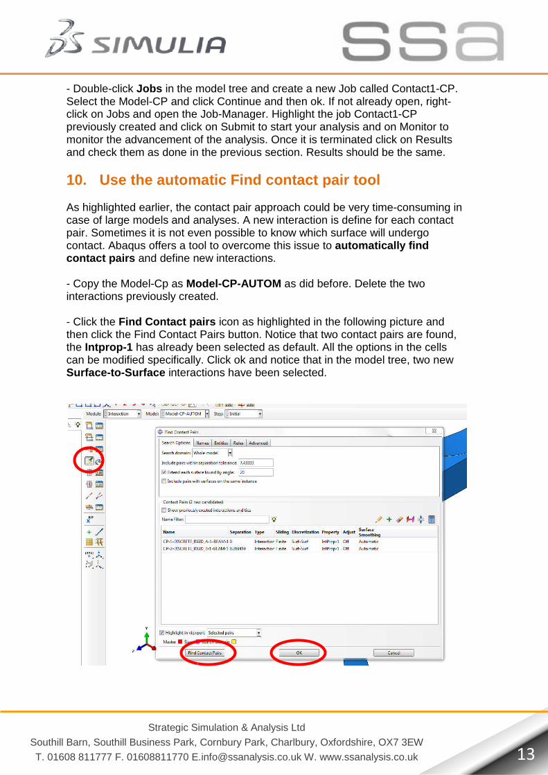
10. Use the automatic Find contact pair tool As highlighted earlier, the contact paircase of large models and analyses. pair. Sometimes it is not even possible to know which surface will undergo contact. Abaqus offers a tool to overcome this issue to contact pairs and define new interactions. - Copy the Model-Cp as Modelinteractions previously created. - Click the Find Contact pairsthen click the Find Contact Pairs button. Notice that two contact pairs are found, the Intprop-1 has already been selecan be modified specifically. Click ok and notice that in the model tree, two new Surface-to-Surface interactions have been selected.
Strategic Simulation & Analysis Ltd
Southill Barn, Southill Business Park, Cornbury Park, Charlbury, Oxfordshire, OX7 3EW
[email protected] W. www.ssanalysis.co.uk
in the model tree and create a new Job called Contact1CP and click Continue and then ok. If not already open
click on Jobs and open the Job-Manager. Highlight the job Contact1previously created and click on Submit to start your analysis and on monitor the advancement of the analysis. Once it is terminated click on Results
done in the previous section. Results should be the same.
Use the automatic Find contact pair tool
As highlighted earlier, the contact pair approach could be very time-case of large models and analyses. A new interaction is define for each contact pair. Sometimes it is not even possible to know which surface will undergo
Abaqus offers a tool to overcome this issue to automatically find and define new interactions.
Model-CP-AUTOM as did before. Delete the two created.
Find Contact pairs icon as highlighted in the following picture and Find Contact Pairs button. Notice that two contact pairs are found, has already been selected as default. All the options in the cells
can be modified specifically. Click ok and notice that in the model tree, two new interactions have been selected.
Southill Barn, Southill Business Park, Cornbury Park, Charlbury, Oxfordshire, OX7 3EW
[email protected] W. www.ssanalysis.co.uk 13
Contact1-CP. ready open, right-
Contact1-CP to start your analysis and on Monitor to
monitor the advancement of the analysis. Once it is terminated click on Results Results should be the same.
-consuming in for each contact
pair. Sometimes it is not even possible to know which surface will undergo automatically find
before. Delete the two
picture and Find Contact Pairs button. Notice that two contact pairs are found,
cted as default. All the options in the cells can be modified specifically. Click ok and notice that in the model tree, two new

Strategic Simulation & Analysis Ltd
Southill Barn, Southill Business Park, Cornbury Park, Charlbury, Oxfordshire, OX7 3EW
T. 01608 811777 F. 01608811770 [email protected] W. www.ssanalysis.co.uk
- Double-click Jobs in the model tree and create a new Job called AUTOM. Select the Model-opening the Job Manager, you can also rightand select Submit to start your analysis and of the analysis. Results can be accessed with this method as well.
Strategic Simulation & Analysis Ltd
Southill Barn, Southill Business Park, Cornbury Park, Charlbury, Oxfordshire, OX7 3EW
[email protected] W. www.ssanalysis.co.uk
in the model tree and create a new Job called Contact1-CP-AUTOM and click Continue and then ok.
opening the Job Manager, you can also right-click the Job Contact1to start your analysis and Monitor to monitor the advancement
Results can be accessed with this method as well.
Southill Barn, Southill Business Park, Cornbury Park, Charlbury, Oxfordshire, OX7 3EW
[email protected] W. www.ssanalysis.co.uk 14
Contact1-CP-AUTOM and click Continue and then ok. Without
-CP_AUTOM to monitor the advancement