Embed Size (px)
Citation preview

Pivonka and Pugh -1-
Three-Stage Coil Gun
Final Project Report December 8, 2006
E155
Dan Pivonka and Michael Pugh
Abstract: A coil gun is an electronic gun that fires a projectile by means of the magnetic field generated when a large pulse of current is run through a coil. In this project, a projectile was propelled by three separate coils that were precisely fired to maximize acceleration. Sets of two DC capacitors in series drove the large pulses of current through coils constructed from magnetic wire. Before both the second and the third coils, a pair of laser diodes and photo sensors measured the velocity of the projectile, which was used to compute the optimum firing time for the next coil. Two final sets of lasers and photo sensors gauged the exit velocity, and this was shown on a seven-segment display. During testing and demonstration, the gun successfully fired all three coils; however, due to weak laser diodes, the system occasionally would incorrectly measure exit velocity and not completely reset, preventing immediate, repeat firing.

Pivonka and Pugh -2-
Introduction
The idea of electromagnetic guns has been around since roughly the 1900s, but
they have not been developed into many practical applications. They have been proposed
for applications such as delivering payloads into space; however this technology has not
yet been developed. There are two main types of electromagnetic guns: coil guns and rail
guns. Both have been shown to reach supersonic speeds, however this coil gun was not
designed to exceed velocities of a few meters per second due to safety concerns.
In this project, the team created control and velocity measurement circuitry for a
coil gun powered by DC capacitors and coils. The coil gun accelerates the projectile by
running a strong impulse of current through a coil of wire with many turns, creating a
powerful magnetic field that accelerates a metal projectile. To provide the impulse of
current, a large DC capacitor discharges very quickly through the coil of wire. In order to
optimize the acceleration of the object, the pulse of current should fire as the projectile
approaches the coil, but should last no longer than the time it takes for the object to reach
the center of the coil. To increase exit velocity, the team created three separate coils
along the barrel of the gun; however, each of these needs to be precisely activated. The
specific firing time is determined by a velocity measurement between two photo sensors.
A final velocity measurement is performed after the last coil fires, and the velocity is
displayed on a seven-segment display. The entire system has been set up to reset after
each shot and recharge the capacitors so that the time between shots is only constrained
by the capacitors’ charging time. A basic outline of the system is shown in the block
diagram in Figure 1.

Pivonka and Pugh -3-
Figure 1: Block Diagram of Firing Circuitry for Coil Gun
The digital part of the project focuses on the control and firing circuitry for the
overall system. It starts by measuring the charge on the firing capacitors through a
voltage division circuit and the A/D converter on the PIC. Based on this measurement,
the PIC continuously provides a signal to the FPGA indicating whether the system is
ready. The FPGA then waits for the trigger signal from the user to fire the first coil. The
projectile fires through the barrel and sequentially blocks the first pair of laser diodes and
photo sensors. The FPGA receives the outputs from the photo sensors digitally and sends
an interrupt signal to the PIC as each photo sensor is blocked. The PIC starts a timer
when it receives the first interrupt from the FPGA and measures the timer on the second
interrupt, and it can then calculate the velocity of the projectile. From this velocity, the
PIC determines the exact time it needs to fire the next coil and generates an interrupt
when this time is reached. This interrupt sends a signal to the FPGA, and the FGPA then
fires the next coil in line. The fire signals from the PIC are amplified with operational
amplifiers to 15V, which is then applied to the gate of a power MOSFET to open the
channel and fire the coil.

Pivonka and Pugh -4-
Schematics
Figure 2: Overall System Schematic

Pivonka and Pugh -5-
17 V -17 V
17 V -17 V
17 V -17 V
Figu
re 3
: C
harg
ing
and
Firi
ng C
ircu
itry
Sche
mat
ic

Pivonka and Pugh -6-
3.3V
800 ohm
Digital Output
Photosensitive Transistor
Figure 4: Single Photo Sensor Schematic (6used)
Figure 5: Seven Segment Display Schematic
Microcontroller Design
The PIC microcontroller has two primary functions in this design. The first is to
measure the charge of the capacitor banks and allow firing of the coils only when they are
completely charged. This is accomplished using the PIC’s built in A/D converter. As

Pivonka and Pugh -7-
shown in Figure 6, two resistors in series were connected from the power supply line to
ground, creating a voltage divider that would divide a 50 V drop across both resistors into
an approximately 2.6 V drop across the second resistor. The PIC’s A/D converter was
connected between the resistors and programmed to use the internal 3.3 V and ground as
the reference high and low voltages. After initializing these settings, the PIC waits in a
while loop and samples the A/D input as quickly as possible. When it finally reads a
value greater than the number corresponding to 2.5 V, the PIC knows the capacitor banks
are charged. It sends a signal telling the FPGA that the system is ready to fire and moves
into the next module of code.
The second function of the PIC is to calculate velocity values using the inputs
from the photo sensors and to predict the best time to fire the secondary coils. The FPGA
helps simplify these tasks by combining all the photo sensor outputs into a single
interrupt sent to the PIC and by firing the correct coil from only a single fire output from
the PIC. This allows the same procedure to be used regardless of which photo sensor pair
was triggered. The second module of code begins by setting up an interrupt to trigger on
the rising edge of an input to port INT0 and initializing a counter at a value of six. The
main code then continually loops until the counter reaches zero.
When port INT0, which is connected to the interrupt output of the FPGA, goes
high, the PIC jumps to an interrupt section. Here, the PIC uses the value of the counter to
determine whether the interrupt came from the first or second sensor in a pair. If it is the
first sensor, i.e. the counter is even, an internal timer is set to zero and initiated. However,
if it is the second sensor, the time is recorded from the sensor and two calculations are
performed. The velocity of the projectile is determined by dividing the distance between
sensors by the recorded time and is sent to the FPGA via the serial port. The optimum
time to fire is then calculated by dividing the distance to the center of the coil by the
projectile’s velocity and subtracting the coil’s firing time. This calculation makes the
assumption that the deceleration due to friction is small enough and the period of
acceleration when the coil fires is short enough so that the velocity of the projectile can
be treated as constant. The result is loaded into a compare register, and compare
interrupts are enabled. Regardless of which photo sensor was fired, the counter is
decremented by one.
Pivonka and Pugh -8-
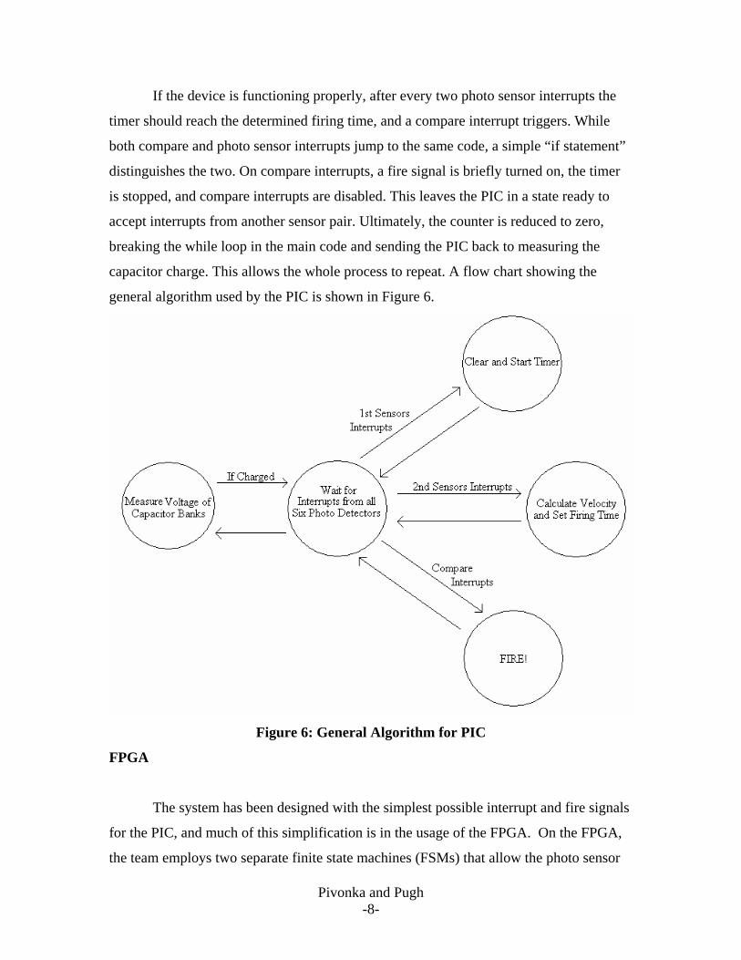
If the device is functioning properly, after every two photo sensor interrupts the
timer should reach the determined firing time, and a compare interrupt triggers. While
both compare and photo sensor interrupts jump to the same code, a simple “if statement”
distinguishes the two. On compare interrupts, a fire signal is briefly turned on, the timer
is stopped, and compare interrupts are disabled. This leaves the PIC in a state ready to
accept interrupts from another sensor pair. Ultimately, the counter is reduced to zero,
breaking the while loop in the main code and sending the PIC back to measuring the
capacitor charge. This allows the whole process to repeat. A flow chart showing the
general algorithm used by the PIC is shown in Figure 6.
Figure 6: General Algorithm for PIC
FPGA
The system has been designed with the simplest possible interrupt and fire signals
for the PIC, and much of this simplification is in the usage of the FPGA. On the FPGA,
the team employs two separate finite state machines (FSMs) that allow the photo sensor

Pivonka and Pugh -9-
interrupts and the fire signal for each stage to be consolidated to a single PIC pin each.
The firing FSM, shown in Figure 7, will send signals to each of the three capacitor sets,
discharging them at the correct time. The FSM waits in the first state until both the
charge ready signal from the PIC and the trigger signal from the user go high. When this
occurs, the discharge signal for only the first coil, Coil[0], will turn on. The rest of the
firing sequence is controlled by the Fire input from the PIC. As explained in the
Microcontroller Design section, this signal briefly goes high at the instant the PIC
calculates to be the optimum firing time for the secondary coils. The third state is reached
when Fire rises for the first time and turns on the discharge signal for the second coil,
Coil[1]. An intermediate state, which is only reached when the fire signal goes low again,
prevents the third coil from immediately firing. The same procedure is used for the final
two states, allowing the next rise and fall of the Fire signal to discharge the last coil via
Coil[2]. Finally, a third Fire signal, calculated by the PIC as the best time to discharge a
non-existent fourth coil, indicates that the projectile has completely passed through the
third coil, and the FSM returns to the initial state, shutting off all three of the Coil
outputs.

Pivonka and Pugh -10-
Figure 7: State Transition Diagram for the Coil Firing
The second FSM generates an interrupt signal for the PIC based on the inputs
from the photo sensors. The photo sensor inputs are represented by the bits photo[5:0].
The FSM remains in its initial state until both the first coil has fired and the first photo
sensor had been blocked. When both of these conditions are met, it moves into its next
state, which sends a digital interrupt to the PIC. The system then immediately moves into
its third state, in which the interrupt signal is set low. It remains in the third state until
the second photo sensor is blocked, and it then moves into a state in which the digital
interrupt is again set high. This process is repeated until the system has sent a digital
interrupt for each photo sensor. After all of the interrupts have occurred, the FSM returns
to its initial state and waits for both a trigger input from the user and for the first photo
sensor to again be blocked by the projectile. A state diagram is shown in Figure 8.

Pivonka and Pugh -11-
Figure 8: State Transition Diagram for Photo Sensor Interrupts
Finally, the FPGA receives the calculated exit velocities from the serial port on
the PIC and shows the result in hexadecimal on a dual seven-segment display. These
modules are attached in appendix B.
Pivonka and Pugh -12-
Results
The coil gun successfully fired and there was significant improvement with each
successive stage. It was able to measure the charge on the capacitors, to take the trigger
input from the user, and to measure the velocity and precisely fire the second and third
stages. The projectile reached speeds of approximately 4m/s, which was near the
expectation. Despite many successful demonstrations, the system did experience a lack
of robustness due to the fairly dim laser diodes and problems with alignment in the photo
sensors. To remedy these problems, the team ran the laser diodes well above their rated
voltage, and with this change every part of the system did function properly most of the
time. However, the laser diodes could not be left on because of the danger of burning
them out, and turning the lasers on and off made continuous firing without reset difficult.

Pivonka and Pugh -13-
References IN5408 Data Sheet http://www.datasheetcatalog.com/datasheets_pdf/I/N/5/4/IN5408.shtml Laser Diode Catalog sheet http://dkc3.digikey.com/PDF/T063/1933.pdf Coil Gun Information http://www.oz.net/~coilgun/home.htm Special thanks to Ted Jiang for his work on the analog circuitry. Parts List: Item Description Source Cost 17mF DC Capacitors Stock Room $0.00 Power Supplies Stock Room $0.00 IN5408 Diodes Stock Room $0.00 5mW Laser Diodes (6) Digi-Key $32.00 Photo Transistors (6) Digi-Key $2.50 MOSFET Transistors Digi-Key $30.00 15 Gauge Magnetic Wire RVac $25.00

Pivonka and Pugh -14-
Appendix A: Micro Chip Code // Dan Pivonka and Michael Pugh // ALong with FPGA controls the firing of three stage coil gun // Load files for PIC #include <p18f452.h> #include <timers.h> /* Global Variables*/ // (5 cm)Distance between set of sensors in meters/(1.6 e-5) unsigned int sDist = 0xC35; // (15 cm)Distance from 1st sensors to coil in meters/(1.6 e-5) unsigned int cDist = 0x249F; // (.01s)Time of pulse in 2nd coil in seconds/(1.6 e-6) unsigned int pTime = 0x186A; // Temp variable unsigned int time; // Counter for photo sensor interrupts char counter = 6; // Min value A/D converter will read when caps charged unsigned int voltage = 0xBE00, a = 0x00; /* Function Prototypes */ void main(void); void isr(void); // Interrupts jump to isr method #pragma code low_vector = 0x18 void low_interrupt(void) { _asm GOTO isr _endasm } #pragma code void main(void) { TRISE = 0x00; TRISA = 0xff; TRISC = 0x00; TRISD = 0x00; PORTD = 0x00; ADCON1 = 0x00; ADCON0 = 0x8d; SSPCON1 = 0x20; //enables serial port SSPSTAT = 0xC0; //Data on rising edge while(1) { // PORT E tells FPGA when capacitors are charging // (1 = charging, 0 = system ready to fire) PORTE = 0x01; while (a < voltage) {

Pivonka and Pugh -15-
while ((ADCON0 > 0x89)) { } a = (ADRESH*0x100)+ADRESL; ADCON0 = 0x8d; } // Once charge is reached we reset the analog measurement // and turn off PORT E a = 0x0000; PORTE = 0x00; TRISB = 1; // Read interrupt signal from port B0(int0) // Set up compare register CCP1CON = 0x0A; CCPR1L = 0x00; CCPR1H = 0x00; // Interrupt when timer1 compares to CCP1 or INT0 rises INTCON = 0xD0; // enable global, peripheral, // and INT0 external intrpts INTCON2 = 0x40; // sets external intrpt to rising edge PIR1 = 0x00; // Clears peripheral flags // Set timer1 to 16-bit read/write and 1:8 prescale T1CON = 0xB0; counter = 0x06; // Loop until counter reaches zero, // indicating 6 photo sensor intrpts while(counter > 0x00) { } } } #pragma interruptlow isr void isr(void) { if (INTCONbits.INT0IF) { // If next sensor was triggered if ((counter & 0x01)) { // If second of sensor pair time = TMR1L; // Take time from timer time = time + (TMR1H * 0x100); // Calculate velocity in m/s, send to FPGA SSPBUF = (sDist*0xA)/(time); // Calculate firing time time = (cDist/sDist)*time-pTime; // Load firing time into compare register CCPR1L = time; CCPR1H = time/0x100; PIE1 = 0x04; // enable compare interrupt } else { //if first of sensor pair TMR1H = 0x00; // Clear timer TMR1L = 0x00; T1CONbits.TMR1ON = 1; // Turn it on

Pivonka and Pugh -16-
PORTE = 0x01; // Disable ready signal } INTCONbits.INT0IF = 0; // Resets flag for external intrpt counter--; // Decrement counter } else { PORTD = 0x01; // Send fire signal T1CONbits.TMR1ON = 0; // Turn off timer PIR1bits.CCP1IF = 0; // Resets flag for compare intrpt PORTD = 0x00; // Turn off fire signal PIE1 = 0x00; // disable compare interrupt } return; }

Pivonka and Pugh -17-
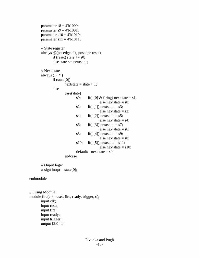
Appendix B: Verilog Code // Top Level Module module Main(clk, reset, SCK, data, photo, trigger, ready, interrupt, fire, coil, seg, d1, d2); input clk; input reset; input SCK; input data; input ready; input fire; input [5:0] photo; input trigger; output interrupt; output [2:0] coil; output [6:0] seg; output d1; output d2; wire [7:0] num; serialdata serialdata1(SCK, data, reset, num); sevensegout sevensegout1(clk, reset, num, seg, d1, d2); photo photo1(clk, reset, photo, coil[0], interrupt); fire fire1(clk, reset, fire, ready, trigger, coil); endmodule // Photo Sensor Interrupts Module module photo(clk, reset, p, firing, intrpt);
input clk; input reset; input [5:0] p; input firing; output intrpt; reg[3:0] state, nextstate; parameter s0 = 4'b1100; parameter s1 = 4'b0001; parameter s2 = 4'b0010; parameter s3 = 4'b0011; parameter s4 = 4'b0100; parameter s5 = 4'b0101; parameter s6 = 4'b0110; parameter s7 = 4'b0111;
Pivonka and Pugh -18-
parameter s8 = 4'b1000; parameter s9 = 4'b1001; parameter s10 = 4'b1010; parameter s11 = 4'b1011; // State register always @(posedge clk, posedge reset) if (reset) state <= s0; else state <= nextstate; // Next state always @( * ) if (state[0]) nextstate = state + 1; else case(state) s0: if(p[0] & firing) nextstate = s1; else nextstate = s0; s2: if(p[1]) nextstate = s3; else nextstate = s2; s4: if(p[2]) nextstate = s5; else nextstate = s4; s6: if(p[3]) nextstate = s7; else nextstate = s6; s8: if(p[4]) nextstate = s9; else nextstate = s8; s10: if(p[5]) nextstate = s11; else nextstate = s10; default: nextstate = s0; endcase // Ouput logic assign intrpt = state[0]; endmodule // Firing Module module fire(clk, reset, fire, ready, trigger, c); input clk; input reset; input fire; input ready; input trigger; output [2:0] c;

Pivonka and Pugh -19-
reg[3:0] state, nextstate; parameter s0 = 4'b0000; parameter s1 = 4'b0001; parameter s2 = 4'b0011; parameter s3 = 4'b1011; parameter s4 = 4'b0111; parameter s5 = 4'b1111; // State register always @(posedge clk, posedge reset) if (reset) state <= s0; else state <= nextstate; // Next state always @( * ) case(state) s0: if(~ready & trigger) nextstate = s1; else nextstate = s0; s1: if(fire) nextstate = s2; else nextstate = s1; s2: if(fire) nextstate = s2; else nextstate = s3; s3: if(fire) nextstate = s4; else nextstate = s3; s4: if(fire) nextstate = s4; else nextstate = s5; s5: if(fire) nextstate = s0; else nextstate = s5; default: nextstate = s0; endcase // Output logic assign c = state[2:0]; endmodule // Serial Data Module module serialdata(SCK,data,reset,shift); input SCK; input data; input reset; output reg [7:0] shift; always@(posedge SCK, posedge reset)

Pivonka and Pugh -20-
begin if (reset) shift <= 8'b00000000; else begin shift[0]<= data; shift[1]<= shift[0]; shift[2]<= shift[1]; shift[3]<= shift[2]; shift[4]<= shift[3]; shift[5]<= shift[4]; shift[6]<= shift[5]; shift[7]<= shift[6]; end end endmodule // Seven Segment Module module sevensegout(clk, reset, num, seg, d1, d2); input clk; input reset; input [7:0] num; output reg [6:0] seg; output reg d1; output reg d2; reg [16:0] m; reg [3:0] display; //10 bit counter to slow the clock always@(posedge clk, posedge reset) begin if (reset) m = 0; else m = (m+1); d1 = m[16]; d2 = ~m[16]; end //multiplexor selects output always@( * ) begin if (reset) display = 4'b0000; else if (m[16]) display = num[3:0];

Pivonka and Pugh -21-
else if (~m[16]) display = num[7:4]; // case statement for the seg output case(display) 0: seg = 7'b000_0001; 1: seg = 7'b100_1111; 2: seg = 7'b001_0010; 3: seg = 7'b000_0110; 4: seg = 7'b100_1100; 5: seg = 7'b010_0100; 6: seg = 7'b010_0000; 7: seg = 7'b000_1111; 8: seg = 7'b000_0000; 9: seg = 7'b000_0100; 10: seg = 7'b000_1000; 11: seg = 7'b110_0000; 12: seg = 7'b111_0010; 13: seg = 7'b100_0010; 14: seg = 7'b011_0000; 15: seg = 7'b011_1000; default: seg = 7'b111_1111; endcase end endmodule