Embed Size (px)
Citation preview


The Threshold CAS 1 is the first high fidelity power amplifier to operate all signal carrying transistors in the cascode mode. As a result the CAS 1 achieves its superior performance through realizing those benefits that accrue from cascode operation not only at the "front end" gain stages, but within the power output stages as well, where the audible advantages of cascoding are especially significant.
The basis for this unique capability of the CAS 1 is the Threshold cascode circuit (patent pending) that enables cascode operation throughout the amplifier's entire signal path. To understand the advantages to cascode operation, it is first necessary to note that all distortion to which a transistor is subject during operation is due to only two varieties of gain nonlinearities: those related to current fluctuations through the transistor and those related to voltage fluctuations across the transistor. As the transistor wanders through these regions in reproducing the audio signal its gain characteristics alter, causing both harmonic and inter-modulation distortion effects.
The Threshold cascode circuit actively clamps the voltage across the signal carrying transistors to a constant value, thereby suppressing voltage fluctuations to near zero levels. In this way the source of one entire class of nonlinearities to which transistors are subject during operation is essentially eliminated. Because "compressive" intermodulation is the characteristic of distortion arising from voltage fluctuation effects, the CAS 1 exhibits a perceived dynamic capability in the processing of transient material considerably in excess of what its rated power would suggest.
Besides eliminating voltage induced nonlinearities, cascode operation yields an additional benefit in increased bandwidth over conventional circuits. Because the collector-base voltage is held constant, there is minimal charging of the collector-base junction capacitance in the transistor. Eliminating the effects of this internal lag capacitance allows an extremely wide frequency bandwidth to be achieved.
Even within its conservative cost and power range the CAS 1 employs those creative circuit innovations that have set Threshold designs apart and it exhibits edge of the art signal resolution, with a sense of effortlessness, regardless of the "difficulty" of the loudspeaker load. Unlike conventional designs, the CAS 1 does not require the application of lag compensation in the signal path and it exhibits the sonic purity, with freedom from transient intermodulation distortion, of a simple system employing few active devices in the
signal path and low open loop gain. Its current limiting, used to insure that the output devices can not enter potentially damaging regions of operation, is held independent of the load's reactance characteristics to assure absolute freedom from false triggering in response to these varying characteristics. Finally, isolating the signal from even the most minute interference, the CAS 1 employs dual power supplies and active current sourcing throughout to fully suppress interchannel power supply effects. Built to the most demanding standards of construction and reliability, the Threshold CAS 1 marks a significant and audible advance in audio amplifier design upon which a full product line draws its inspiration. The CAS 1 stands as a benchmark in the performance that can be anticipated from components designed to conservative power standards.
The internal construction of the CAS 1, as in all Threshold products, is unparalleled. An extremely heavy gauge chassis supports the large twin power supplies and thick aluminum "T " beam extrusions upon which the amplifying channels are mounted. All active electronic components are individually selected and tested to insure absolute channel-to-channel and unit-to-unit consistency. Only low noise metal film resistors and tantalum capacitors are used in the signal path.
Threshold model CAS 1 cascode power amplifier
Threshold model 400A class A power amplifier
Threshold now commands a reputation for visionary design precepts realized in the most practical and rugged embodiments. The model 400A class A power amplifier is the cornerstone for this reputation and is the product of a resolve to apply every technical resource toward making the high power class A solid-state amplifier an audio reality.
Class A amplification has long been recognized as an ideal in state of the art amplifier design as it yields the smoothest transfer functions, widest bandwidths and significantly reduces the amount of feedback required. However, until now, its realization in solid-state technology has been unable to achieve the power levels and stability margins for the full dynamic potential expected of today's equipment and required by tomorrow's program sources.
The Threshold 400A is a completely new class A design that meets these power criteria and provides virtually perfect signal processing insofar as aural perception is concerned. This is achieved through the use of an ingeniously simple signal path, "front end" cascoding and the operation of all gain transistors throughout the amplifier, front end and power output stages, in the class A mode.
To realize these conditions without the cost and efficiency penalties that have inhibited previous class A designs the Threshold 400A employs a unique, original and patented dynamic biasing circuit. This circuit senses the internal bias needs continuously and instantaneously tracks the bias voltage to the levels required for maintaining constant class A operation of all output transistors at all times and under all signal conditions to rated swing. This circuit allows the Threshold 400A to idle at one-fourth the power of an equivalently rated conventional class A design yet maintain full class A operation, with its acknowledged superiority, over an enormous range of output power.
As a result the Threshold 400A power amplifier marks a turning point in the development of class A amplification as it breaks free of the power, cost and efficiency barriers that have frustrated conventional class A designs. With its new circuit configuration the 400A achieves the purity of class A operation at output and reserve power levels previously considered impractical to attempt in a class A solid-state amplifier for the home.
Through its class A operating mode the 400A eliminates those distortion products resulting from transistor turn-on, turn-off delays, restricting the residual components to low-
order harmonics and simple modulations. These are not only least offensive to the human ear, but sharply reduce the amount of negative feed back required at high frequencies so that transient intermodulation effects are no longer a problem and high voltage and current slewing can be achieved with absolute stability.
The pacesetting concepts of the Threshold 400A have made possible the unchallenged excellence of class A operation at power, size, reliability and cost levels competitive with conventional high fidelity power amplifiers.
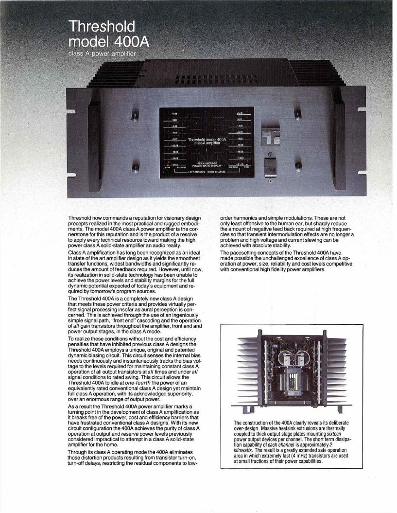
The construction of the 400A clearly reveals its deliberate over-design. Massive heatsink extrusions are thermally coupled to thick output stage plates mounting sixteen power output devices per channel. The short term dissipation capability of each channel is approximately 2 kilowatts. The result is a greatly extended safe operation area in which extremely fast (4 mHz) transistors are used at small fractions of their power capabilities.

Threshold model 4000 cascode/class A power-amplifier
With the model 4000 power amplifier Threshold has extended the limits of electronic design and performance by bringing to synergism cascode and class A operation in a single, extraordinary amplifying system. Engineered for those applications demanding immense output reserves, with signal accuracy encompassing the furthest reaches of power amplifier technology, the Threshold 4000 serves as a basis upon which to realize an uncompromised audio system.
Building upon those superior capabilities afforded, individually, by the operating modes of the CAS 1 and 400A amplifiers,the Threshold 4000 combines both designs into a unique circuit configuration that performs to new levels of accuracy. All amplifying devices within the signal path of all gain stages of the 4000, both front-end and power output, are operated in class A a n d cascode for maximum suppression of anomalies in transistor action. The Threshold cascode circuits and patented dynamic class A bias employed in the 4000 are incorporated into channel output stages whose extremely fast (4mHz) output devices carry a combined dissipation reserve approaching six kilowatts. The extraordinarily wide performance margins afforded by its high speed circuitry and huge power potential simply obviate considerations of load "suitability" where the 4000 is concerned.
As in all Threshold products the design of the 4000 follows the basic Threshold precept that superior results are obtained when the gain path is kept simple and requires minimal correction. To achieve these conditions signal bearing transistors are individually selected and integrated with complex peripheral circuits. These circuits are employed to assure that all signal carrying devices in the 4000 are held in their most linear operating regions at all times, through the widest signal extremes and under the most demanding power requirements. Power for the 4000 is supplied by a one kilowatt transformer feeding independent supplies for each channel through high capacity bridges and Threshold specified power capacitors. Any residual traces of interchannel power supply fluctuation effects are fully suppressed through gain circuitry employing active current sourcing at every stage to achieve the highest rejection levels.
For applications in which the stereo power rating of the 4000 is insufficient rear panel capability is provided, without tools, to "bridge" the amplifier and achieve monophonic op
eration of substantially increased output power. When converted to "bridged" mode this operating configuration is then displayed on the front panel of the 4000 by a glowing LED indicator. The cascode/class A operating conditions of the circuits, speed, frequency response and capability of the amplifier to work into reactive loads is unaffected. The Threshold 4000 demands serious consideration when the highest levels of power and performance are required. The cascode/class A operation, individually selected components, painstaking assembly and thorough testing culminate in a product that must be acknowledged a position at the leading edge of the art.
The interior of the 4000 quickly reveals the Threshold characteristic of extraordinarily robust construction. Forty-eight high power output devices are secured in intimate thermal contact to the industry's largest heat sink extrusions. Twin, high capacity supplies provide thoroughly regulated power from a massive transformer. Extra heavy gauge sheet metal and "overkill" fastenings result in a rigid, flex-free housing for the most advanced audio circuitry.
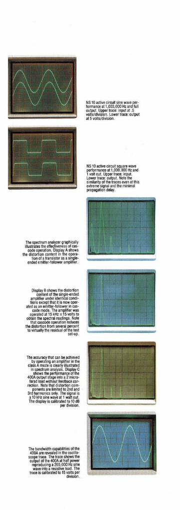
NS10 active circuit sine wave performance at 1,000,000 Hz and full output. Upper trace: input at .5 volts/division. Lower trace: output at 5 volts/division.
NS 10 active circuit square wave performance at 1,000,000 Hz and 1 volt out. Upper trace: input. Lower trace: output. Note the similarity of the traces even at this extreme signal and the minimal propagation delay.
The spectrum analyzer graphically illustrates the effectiveness of cas-
code operation. Display A shows the distortion content in the opera
tion of a transistor as a single-ended emitter-follower amplifier.
Display B shows the distortion content of the single-ended
amplifier under identical conditions except that it is now oper
ated as an emitter-follower in cas-code mode. The amplifier was
operated at 15 kHz ± 15 volts to obtain the spectral readings. Note
that cascode operation reduces the distortion from several percent to virtually the residual of the test
set-up.
The accuracy that can be achieved by operating an amplifier in the
class A mode is clearly illustrated in spectrum analysis. Display C
shows the performance of the 400A output stage Into a 2 microfarad load without feedback cor
rection. Note that distortion components are limited to 2nd and
3rd harmonics only. The signal is a 10 kHz sine wave at 1 watt out. The display is calibrated to 10 dB
per division.
The bandwidth capabilities of the 400A are revealed in the oscillo
scope trace. The trace shows the output of the 400A at half power reproducing a 200,000 Hz sine wave into a resistive load. The
trace is calibrated to 15 volts per division.
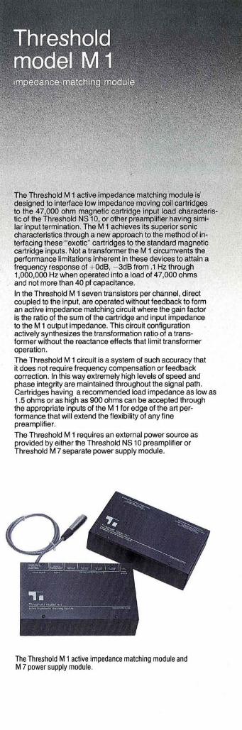
Threshold model M1
The Threshold M 1 active impedance matching module is designed to interface low impedance moving coil cartridges to the 47,000 ohm magnetic cartridge input load characteristic of the Threshold NS 10, or other preamplifier having similar input termination. The M1 achieves its superior sonic characteristics through a new approach to the method of interfacing these "exotic" cartridges to the standard magnetic cartridge inputs. Not a transformer the M1 circumvents the performance limitations inherent in these devices to attain a frequency response of +0dB, - 3 d B from .1 Hz through 1,000,000 Hz when operated into a load of 47,000 ohms and not more than 40 pf capacitance.
In the Threshold M1 seven transistors per channel, direct coupled to the input, are operated without feedback to form an active impedance matching circuit where the gain factor is the ratio of the sum of the cartridge and input impedance to the M1 output impedance. This circuit configuration actively synthesizes the transformation ratio of a transformer without the reactance effects that limit transformer operation. The Threshold M1 circuit is a system of such accuracy that it does not require frequency compensation or feedback correction. In this way extremely high levels of speed and phase integrity are maintained throughout the signal path. Cartridges having a recommended load impedance as low as 1.5 ohms or as high as 900 ohms can be accepted through the appropriate inputs of the M1 for edge of the art performance that will extend the flexibility of any fine preamplifier.
The Threshold M 1 requires an external power source as provided by either the Threshold NS 10 preamplifier or Threshold M 7 separate power supply module.
The Threshold M1 active impedance matching module and M 7 power supply module.
impedance matching module
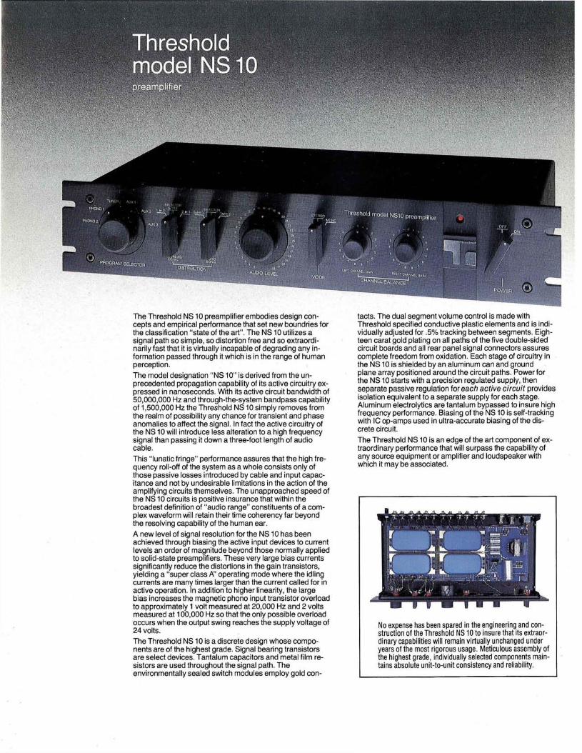
The Threshold NS 10 preamplifier embodies design concepts and empirical performance that set new boundries for the classification "state of the art". The NS 10 utilizes a signal path so simple, so distortion free and so extraordinarily fast that it is virtually incapable of degrading any information passed through it which is in the range of human perception.
The model designation "NS 10" is derived from the unprecedented propagation capability of its active circuitry expressed in nanoseconds. With its active circuit bandwidth of 50,000,000 Hz and through-the-system bandpass capability of 1,500,000 Hz the Threshold NS 10 simply removes from the realm of possibility any chance for transient and phase anomalies to affect the signal. In fact the active circuitry of the NS 10 will introduce less alteration to a high frequency signal than passing it down a three-foot length of audio cable.
This "lunatic fringe" performance assures that the high frequency roll-off of the system as a whole consists only of those passive losses introduced by cable and input capacitance and not by undesirable limitations in the action of the amplifying circuits themselves. The unapproached speed of the NS 10 circuits is positive insurance that within the broadest definition of "audio range" constituents of a complex waveform will retain their time coherency far beyond the resolving capability of the human ear.
A new level of signal resolution for the NS 10 has been achieved through biasing the active input devices to current levels an order of magnitude beyond those normally applied to solid-state preamplifiers. These very large bias currents significantly reduce the distortions in the gain transistors, yielding a "super class A" operating mode where the idling currents are many times larger than the current called for in active operation. In addition to higher linearity, the large bias increases the magnetic phono input transistor overload to approximately 1 volt measured at 20,000 Hz and 2 volts measured at 100,000 Hz so that the only possible overload occurs when the output swing reaches the supply voltage of 24 volts.
The Threshold NS 10 is a discrete design whose components are of the highest grade. Signal bearing transistors are select devices. Tantalum capacitors and metal film resistors are used throughout the signal path. The environmentally sealed switch modules employ gold con
tacts. The dual segment volume control is made with Threshold specified conductive plastic elements and is individually adjusted for .5% tracking between segments. Eighteen carat gold plating on all paths of the five double-sided circuit boards and all rear panel signal connectors assures complete freedom from oxidation. Each stage of circuitry in the NS 10 is shielded by an aluminum can and ground plane array positioned around the circuit paths. Power for the NS 10 starts with a precision regulated supply, then separate passive regulation for each active circuit provides isolation equivalent to a separate supply for each stage. Aluminum electrolytics are tantalum bypassed to insure high frequency performance. Biasing of the NS 10 is self-tracking with IC op-amps used in ultra-accurate biasing of the discrete circuit.
The Threshold NS 10 is an edge of the art component of extraordinary performance that will surpass the capability of any source equipment or amplifier and loudspeaker with which it may be associated.
No expense has been spared in the engineering and construction of the Threshold NS 10 to insure that its extraordinary capabilities will remain virtually unchanged under years of the most rigorous usage. Meticulous assembly of the highest grade, individually selected components maintains absolute unit-to-unit consistency and reliability.
Threshold model NS10 preamplifier
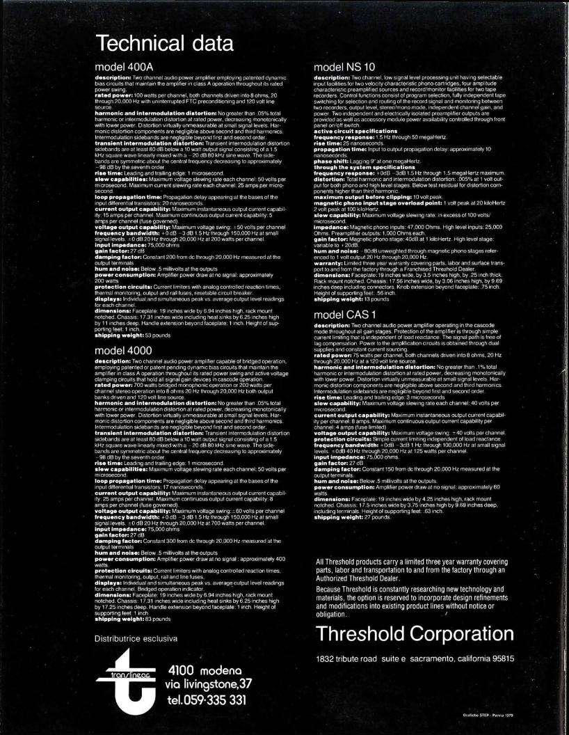
Technical data model 400A model NS10 d e s c r i p t i o n : Two channel audio power amplifier employing patented dynamic bias circuits that maintain the amplifier in class A operation throughout its rated power swjng. r a t e d p o w e r : 100 watts per channel, both channels driven into 8 ohms, 20 through 20,000 Hz with uninterrupted FTC preconditioning and 120 volt line source. h a r m o n i c and in te rmodu la t ion d is tor t ion: No greater than .05% total harmonic or intermodulation distortion at rated power, decreasing monotonically with lower power. Distortion virtually unmeasurable at small signal levels. Harmonic distortion components are negligible above second and third harmonics. Intermodulation sidebands are negligible beyond first and second order, t rans ien t in te rmodu la t ion d is tor t ion: Transient intermodulation distortion sidebands are at least 80 dB below a 10 watt output signal consisting of a 1.5 kHz square wave linearly mixed with a - 20 dB 80 kHz sine wave. The sidebands are symmetric about the central frequency decreasing to approximately -98 dB by the seventh order. r ise t ime: Leading and trailing edge: 1 microsecond. s l e w c a p a b i l i t i e s : Maximum voltage slewing rate each channel: 50 volts per microsecond. Maximum current slewing rate each channel: 25 amps per microsecond. loop p r o p a g a t i o n t ime: Propagation delay appearing at the bases of the input differential transistors: 20 nanoseconds. cur ren t output capab i l i t y : Maximum instantaneous output current capability: 15 amps per channel. Maximum continuous output current capability: 5 amps per channel (fuse governed). vo l tage output capab i l i ty : Maximum voltage swing: ±50 volts per channel f r e q u e n c y b a n d w i d t h : + 0 dB - 3 dB 1.5 Hz through 150,000 Hz at small signal levels. ±0 dB 20 Hz through 20,000 Hz at 200 watts per channel, input i m p e d a n c e : 75,000 ohms g a i n fac tor : 27 dB d a m p i n g fac tor : Constant 200 from dc through 20,000 Hz measured at the output terminals h u m a n d n o i s e : Below .5 millivolts at the outputs p o w e r c o n s u m p t i o n : Amplifier power draw at no signal: approximately 200 watts p r o t e c t i o n c i r c u i t s : Current limiters with analog controlled reaction times, thermal monitoring, output and rail fuses, resetable circuit breaker, d i s p l a y s : Individual.and simultaneous peak vs. average output level readings for each channel. d i m e n s i o n s : Faceplate: 19 inches wide by 6.94 inches high, rack mount notched. Chassis: 17.31 inches wide including heat sinks by 6.25 inches high by 11 inches deep. Handle extension beyond faceplate: 1 inch. Height of supporting feet: 1 inch, s h i p p i n g weight : 53 pounds
model 4000 d e s c r i p t i o n : Two channel audio power amplifier capable of bridged operation, employing patented or patent pending dynamic bias circuits that maintain the amplifier in class A operation throughout its rated power swing and active voltage clamping circuits that hold all signal gain devices in cascode operation, ra ted p o w e r : 700 watts bridged monophonic operation or 200 watts per channel stereo operation into 8 ohms 20 Hz through 20,000 Hz both output banks driven and 120 volt line source. h a r m o n i c a n d in te rmodu la t ion d is tor t ion: No greater than .05% total harmonic or intermodulation distortion at rated power, decreasing monotonically with lower power. Distortion virtually unmeasurable at small signal levels. Harmonic distortion components are negligible above second and third harmonics. Intermodulation sidebands are negligible beyond first and second order, t rans ien t in te rmodu la t ion d is to r t ion : Transient intermodulation distortion sidebands are at least 80 dB below a 10 watt output signal consisting of a 1.5 kHz square wave linearly mixed with a - 20 dB 80 kHz sine wave. The sidebands are symmetric about the central frequency decreasing to approximately - 98 dB by the seventh order. r ise t ime: Leading and trailing edge: 1 microsecond. s l e w c a p a b i l i t i e s : Maximum voltage slewing rate each channel: 50 volts per microsecond. l o o p p r o p a g a t i o n t ime: Propagation delay appearing at the bases of the input differential transistors: 17 nanoseconds. c u r r e n t output capab i l i t y : Maximum instantaneous output current capability: 25 amps per channel. Maximum continuous output current capability: 8 amps per channel (fuse governed). v o l t a g e output capab i l i t y : Maximum voltage swing: ±60 volts per channel f r e q u e n c y b a n d w i d t h : +0 dB - 3 dB 1.5 Hz through 150,000 Hz at small signal levels. ±0 dB 20 Hz through 20,000 Hz at 700 watts per channel, input i m p e d a n c e : 75,000 ohms g a i n f a c t o r : 27 dB d a m p i n g fac tor : Constant 300 from dc through 20,000 Hz measured at the output terminals h u m a n d n o i s e : Below .5 millivolts at the outputs p o w e r c o n s u m p t i o n : Amplifier power draw at no signal: approximately 400 watts. p r o t e c t i o n c i r c u i t s : Current limiters with analog controlled reaction times, thermal monitoring, output, rail and line fuses. d i s p l a y s : Individual and simultaneous peak vs. average output level readings for each channel. Bridged operation indicator. d i m e n s i o n s : Faceplate: 19 inches wide by 6.94 inches high, rack mount notched. Chassis: 17.31 inches wide including heat sinks by 6.25 inches high by 17.25 inches deep. Handle extension beyond faceplate: 1 inch. Height of supporting feet: 1 inch, s h i p p i n g weight : 83 pounds
Dis t r ibu t r i ce esc lus iva
d e s c r i p t i o n : Two channel, low signal level processing unit having selectable input facilities for two velocity characteristic phono cartridges, four amplitude characteristic preamplified sources and record/monitor facilities tor two tape recorders. Control functions consist of program selection, fully independent tape switching for selection and routing of the record signal and monitoring between two recorders, output level, stereo/mono mode, independent channel gain, and power. Two independent and electrically isolated preamplifier outputs are provided as well as accessory module power availability controlled through front panel on/off switch, a c t i v e c i r c u i t s p e c i f i c a t i o n s f r e q u e n c y r e s p o n s e : 1.5 Hz through 50 megaHertz. r ise t ime: 25 nanoseconds. p r o p a g a t i o n t ime: Input to output propagation delay: approximately 10 nanoseconds. p h a s e shift: Lagging 9U at one megaHertz. th rough the s y s t e m s p e c i f i c a t i o n s f r e q u e n c y r e s p o n s e : -i-OdB -3dB1.5Hz through 1.5 megaHertz maximum, d is tor t ion : Total harmonic and intermodulation distortion: .005% at 1 volt output for both phono and high level stages. Below test residual for distortion components higher than third harmonic, m a x i m u m output be fore c l i p p i n g : 10 volt peak. m a g n e t i c p h o n o input s t a g e o v e r l o a d point : 1 volt peak at 20 kiloHertz 2 volt peak at 100 kiloHertz. s l e w capab i l i t y : Maximum voltage slewing rate: in excess of 100 volts/ microsecond. i m p e d a n c e : Magnetic phono inputs: 47,000 Ohms. High level inputs: 25,000 Ohms. Preamplifier outputs: 1,000 Ohms each. ga in fac tor : Magnetic phono stage: 40dB at 1 kiloHertz. High level stage: variable to i-20dB. h u m a n d n o i s e : - 80dB unweighted through magnetic phono stages referenced to 1 volt output 20 Hz through 20,000 Hz. warranty : Limited three year warranty covering parts, labor and surface transport to and from the factory through a Franchised Threshold Dealer, d i m e n s i o n s : Faceplate: 19 inches wide, by 3.5 inches high, by .25 inch thick. Rack mount notched. Chassis: 17.56 inches wide, by 3.06 inches high, by 9.69 inches deep including connectors. Knob extension beyond faceplate: .75 inch. Height of supporting feet: .56 inch, s h i p p i n g weight : 13 pounds
model CAS 1 d e s c r i p t i o n : Two channel audio power amplifier operating in the cascode mode throughout all gain stages. Protection of the amplifier is through simple current limiting that is independent of load reactance. The signal path is free of lag compensation. Power to the amplification circuits is obtained through dual supplies and constant current sourcing. ra ted p o w e r : 75 watts per channel, both channels driven into 8 ohms, 20 Hz through 20,000 Hz at a 120 volt line source. h a r m o n i c a n d in te rmodu la t ion d is tor t ion: No greater than . 1 % total harmonic or intermodulation distortion at rated power, decreasing monotonically with lower power. Distortion virtually unmeasurable at small signal levels. Harmonic distortion components are negligible above second and third harmonics. Intermodulation sidebands are negligible beyond first and second-order, r ise t ime: Leading and trailing edge: 3 microseconds s l e w capab i l i ty : Maximum voltage slewing rate each channel: 40 volts per microsecond. cur ren t output c a p a b i l i t y : Maximum instantaneous output current capability per channel: 8 amps. Maximum continuous output current capability per channel: 4 amps (fuse limited) v o l t a g e output capab i l i t y : Maximum voltage swing: ±40 volts per channel, p r o t e c t i o n c i r c u i t s : Simple current limiting independent of load reactance, f r e q u e n c y b a n d w i d t h : f OdB -3dB 1 Hz through 100,000 Hz at small signal levels. ±0dB 40 Hz through 20,000 Hz at 125 watts per channel, input i m p e d a n c e : 75,000 ohms, ga in fac tor : 27 dB d a m p i n g factor : Constant 150 from dc through 20,000 Hz measured at the output terminals. h u m a n d n o i s e : Below .5 millivolts at the outputs. p o w e r c o n s u m p t i o n : Amplifier power draw at no signal: approximately 60 watts. d i m e n s i o n s : Faceplate: 19 inches wide by 4.25 inches high, rack mount notched. Chassis: 17.5 inches wide by 3.75 inches high by 9.69 inches deep, including terminals. Height of supporting feet: .63 inch, s h i p p i n g weight : 27 pounds.
All Threshold products carry a limited three year warranty covering parts, labor and transportation to and trom the factory through an Authorized Threshold Dealer.
Because Threshold is constantly researching new technology and materials, the option is reserved to incorporate design refinements and modifications into existing product lines without notice or obligation. '
Threshold Corporation
4100 modena via livingstone,37 tel.059-335 331
1832 tr ibute road sui te e sac ramen to , California 95815
Qratlche STEP • Parma 1979