Embed Size (px)
Citation preview
Retractable Thrusters35 kgf / 55 kgf - ø 150 mm60 kgf / 75 kgf / 95 kgf - ø 185 mm
125 kgf / 160 kgf - ø 250 mm
NEDERLANDS 7
ENGLISH 25
DEUTSCH 43
FRANÇAIS 61
ESPAÑOL 79
ITALIANO 97
DANSK 115
SVENSKA 133
NORSK 151
SUOMEKSI 169
Copyright © 2017 Vetus b.v. Schiedam Holland
020584.01
Installatie instructies
Einbauanleitung
Instructions d’installation
Instrucciones de instalación
Istruzioni per l’installazione
Installations instruktioner
Monteringsinstruktioner
Installasjonsinstrukser
Asennusohje
THRUSTER
RETRACTABLE
Installation manual

2 020584.01 vetus® Installation instructions Retractable Thrusters
Inhoud Content
1 Veiligheid . . . . . . . . . . . . . . . . . . . . . . . . . . . . . . . . . . . . . . . . . . . 7
2 Inleiding . . . . . . . . . . . . . . . . . . . . . . . . . . . . . . . . . . . . . . . . . . . . 7
3 Opstelling van de boegschroef . . . . . . . . . . . . . . . . . . . . . . 8
4 Het plaatsen van de behuizing . . . . . . . . . . . . . . . . . . . . . . . 84.1 Opening maken van binnenuit . . . . . . . . . . . . . . . . . . 94.2 Opening maken van buitenaf . . . . . . . . . . . . . . . . . . . 104.3 Afwerken opening . . . . . . . . . . . . . . . . . . . . . . . . . . . . . 124.4 Installatie behuizing . . . . . . . . . . . . . . . . . . . . . . . . . . . 124.5 Het plaatsen van het luik . . . . . . . . . . . . . . . . . . . . . . . 164.6 Inlamineren van de behuizing . . . . . . . . . . . . . . . . . . 17
5 Eindmontage . . . . . . . . . . . . . . . . . . . . . . . . . . . . . . . . . . . . . . 18
6 Elektrische installatie . . . . . . . . . . . . . . . . . . . . . . . . . . . . . . . 196.1 De keuze van de accu . . . . . . . . . . . . . . . . . . . . . . . . . . 196.2 Hoofdstroomkabels (accukabels) . . . . . . . . . . . . . . . 206.3 Hoofdschakelaar . . . . . . . . . . . . . . . . . . . . . . . . . . . . . . . 206.4 Zekering . . . . . . . . . . . . . . . . . . . . . . . . . . . . . . . . . . . . . . 206.5 Aansluiten hoofdstroomkabels . . . . . . . . . . . . . . . . . 216.6 Aansluiten stuurstroomkabels . . . . . . . . . . . . . . . . . . 21
7 Configureren van de installatie . . . . . . . . . . . . . . . . . . . . . 227.1 Configureren van de boeg- en/of hekschroef . . . . 227.2 Instelling voor de grootte van de boegschroef . . . 237.3 Instelling 12 Volt of 24 Volt . . . . . . . . . . . . . . . . . . . . . 237.4 Configureren van de panelen . . . . . . . . . . . . . . . . . . . 23
8 Proefdraaien . . . . . . . . . . . . . . . . . . . . . . . . . . . . . . . . . . . . . . . 24
1 Safety . . . . . . . . . . . . . . . . . . . . . . . . . . . . . . . . . . . . . . . . . . . . . 25
2 Introduction . . . . . . . . . . . . . . . . . . . . . . . . . . . . . . . . . . . . . . . 25
3 Positioning the bow thruster . . . . . . . . . . . . . . . . . . . . . . . 26
4 Fitting the housing . . . . . . . . . . . . . . . . . . . . . . . . . . . . . . . . . 264.1 Making the opening from the inside . . . . . . . . . . . . 274.2 Making the opening from the inside . . . . . . . . . . . . 284.3 Finishing of the opening . . . . . . . . . . . . . . . . . . . . . . . 304.4 Installation of housing . . . . . . . . . . . . . . . . . . . . . . . . . 304.5 Fitting the hatch . . . . . . . . . . . . . . . . . . . . . . . . . . . . . . . 344.6 Laminating the housing . . . . . . . . . . . . . . . . . . . . . . . . 35
5 Final assembly . . . . . . . . . . . . . . . . . . . . . . . . . . . . . . . . . . . . . 36
6 Electrical installation . . . . . . . . . . . . . . . . . . . . . . . . . . . . . . . 376.1 Choice of battery . . . . . . . . . . . . . . . . . . . . . . . . . . . . . . 376.2 Main power cables (battery cables) . . . . . . . . . . . . . 386.3 Main Switch . . . . . . . . . . . . . . . . . . . . . . . . . . . . . . . . . . . 386.4 Fuse . . . . . . . . . . . . . . . . . . . . . . . . . . . . . . . . . . . . . . . . . . 386.5 Connecting main power cables . . . . . . . . . . . . . . . . . 396.6 Connecting control voltage cables . . . . . . . . . . . . . . 39
7 Configuration of the installation . . . . . . . . . . . . . . . . . . . . 407.1 Configuring the bow and / or stern thruster . . . . . 407.2 Setting for the size of the thruster . . . . . . . . . . . . . . . 417.3 Setting 12 or 24 Volt . . . . . . . . . . . . . . . . . . . . . . . . . . . 417.4 Configuring the panels . . . . . . . . . . . . . . . . . . . . . . . . . 41
8 Test run . . . . . . . . . . . . . . . . . . . . . . . . . . . . . . . . . . . . . . . . . . . . 42
Raadpleeg de eigenaarshandleiding voor Bediening, Onderhoud, Storingen en Technische gegevens .’
Consult the owner’s manual for Operation, Maintenance, Trouble shooting and Technical data .
9 Hoofdafmetingen . . . . . . . . . . . . . . . . . . . . . . . . . . . . . . . . . 187
10 Aansluitschema’s . . . . . . . . . . . . . . . . . . . . . . . . . . . . . . . . . . 192
11 Accucapaciteit . . . . . . . . . . . . . . . . . . . . . . . . . . . . . . . . . . . . 198
12 Accukabels . . . . . . . . . . . . . . . . . . . . . . . . . . . . . . . . . . . . . . . 199
9 Principal dimensions . . . . . . . . . . . . . . . . . . . . . . . . . . . . . . 187
10 Wiring diagrams . . . . . . . . . . . . . . . . . . . . . . . . . . . . . . . . . . 192
11 Battery capacity . . . . . . . . . . . . . . . . . . . . . . . . . . . . . . . . . . . 198
12 Battery cables . . . . . . . . . . . . . . . . . . . . . . . . . . . . . . . . . . . . . 199
020584.01 25vetus® Installation instructions Retractable Thrusters
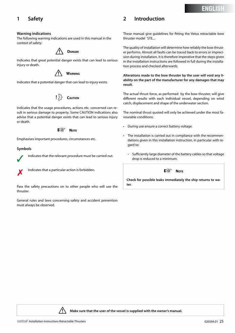
1 Safety
Warning indications The following warning indications are used in this manual in the context of safety:
Danger
Indicates that great potential danger exists that can lead to serious injury or death.
Warning
Indicates that a potential danger that can lead to injury exists.
Caution
Indicates that the usage procedures, actions etc. concerned can re-sult in serious damage to property. Some CAUTION indications also advise that a potential danger exists that can lead to serious injury or death.
note
Emphasises important procedures, circumstances etc.
Symbols
Indicates that the relevant procedure must be carried out.
Indicates that a particular action is forbidden.
Pass the safety precautions on to other people who will use the thruster.
General rules and laws concerning safety and accident prevention must always be observed.
2 Introduction
These manual give guidelines for fitting the Vetus retractable bow thruster model ‘STE....
The quality of installation will determine how reliably the bow thrust-er performs. Almost all faults can be traced back to errors or impreci-sion during installation. It is therefore imperative that the steps given in the installation instructions are followed in full during the installa-tion process and checked afterwards.
Alterations made to the bow thruster by the user will void any li-ability on the part of the manufacturer for any damages that may result .
The actual thrust force, as performed by the bow thruster, will give different results with each individual vessel, depending on wind catch, displacement and shape of the underwater section.
The nominal thrust quoted will only be achieved under the most fa-vourable conditions:
• During use ensure a correct battery voltage.
• The installation is carried out in compliance with the recommen-dations given in this installation instruction, in particular with re-gard to:
- Sufficiently large diameter of the battery cables so that voltage drop is reduced to a minimum.
note
Check for possible leaks immediately the ship returns to wa-ter .
Make sure that the user of the vessel is supplied with the owner’s manual .
ENGLISH
26 020584.01 vetus® Installation instructions Retractable Thrusters
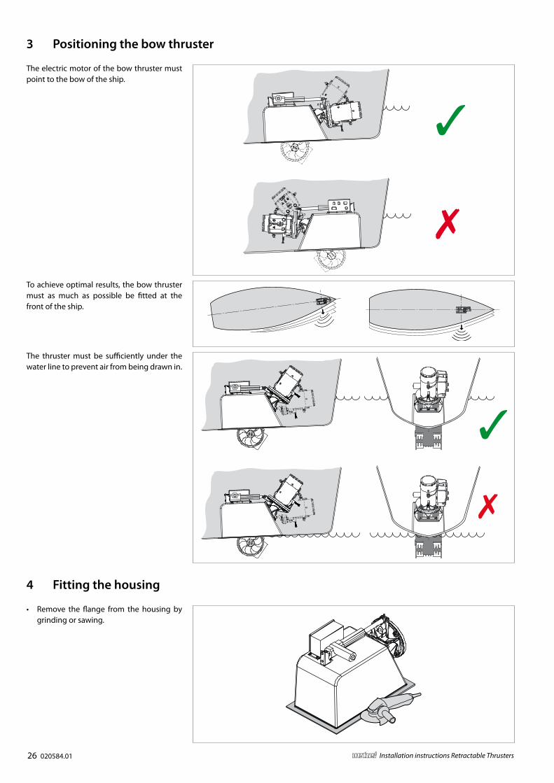
3 Positioning the bow thruster
The thruster must be sufficiently under the water line to prevent air from being drawn in.
The electric motor of the bow thruster must point to the bow of the ship.
To achieve optimal results, the bow thruster must as much as possible be fitted at the front of the ship.
4 Fitting the housing
• Remove the flange from the housing by grinding or sawing.
020584.01 27vetus® Installation instructions Retractable Thrusters
A
BOW
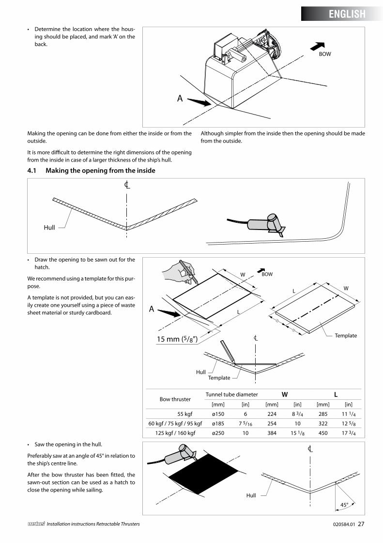
• Determine the location where the hous-ing should be placed, and mark ‘A’ on the back.
Making the opening can be done from either the inside or from the outside.
It is more difficult to determine the right dimensions of the opening from the inside in case of a larger thickness of the ship’s hull.
Although simpler from the inside then the opening should be made from the outside.
Hull
4 .1 Making the opening from the inside
L
W
L W
A
BOW
HullTemplate
Template15 mm (5/8”)
Bow thrusterTunnel tube diameter W L
[mm] [in] [mm] [in] [mm] [in]
35 kgf / 55 kgf ø150 6 224 8 3/4 285 11 1/4
60 kgf / 75 kgf / 95 kgf ø185 7 5/16 254 10 322 12 5/8
125 kgf / 160 kgf ø250 10 384 15 1/8 450 17 3/4
• Draw the opening to be sawn out for the hatch.
We recommend using a template for this pur-pose.
A template is not provided, but you can eas-ily create one yourself using a piece of waste sheet material or sturdy cardboard.
45°
Hull
• Saw the opening in the hull.
Preferably saw at an angle of 45° in relation to the ship’s centre line.
After the bow thruster has been fitted, the sawn-out section can be used as a hatch to close the opening while sailing.
ENGLISH
28 020584.01 vetus® Installation instructions Retractable Thrusters
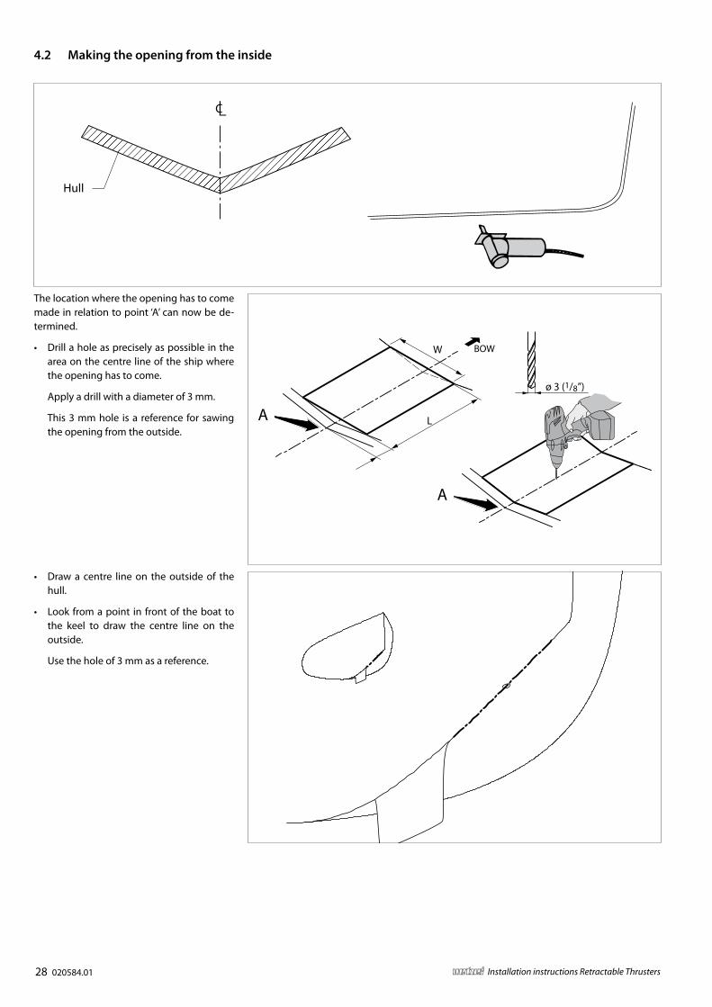
The location where the opening has to come made in relation to point ‘A’ can now be de-termined.
• Drill a hole as precisely as possible in the area on the centre line of the ship where the opening has to come.
Apply a drill with a diameter of 3 mm.
This 3 mm hole is a reference for sawing the opening from the outside.
Hull
4 .2 Making the opening from the inside
L
W
A
A
BOW
ø 3 (1/8”)
• Draw a centre line on the outside of the hull.
• Look from a point in front of the boat to the keel to draw the centre line on the outside.
Use the hole of 3 mm as a reference.
020584.01 29vetus® Installation instructions Retractable Thrusters
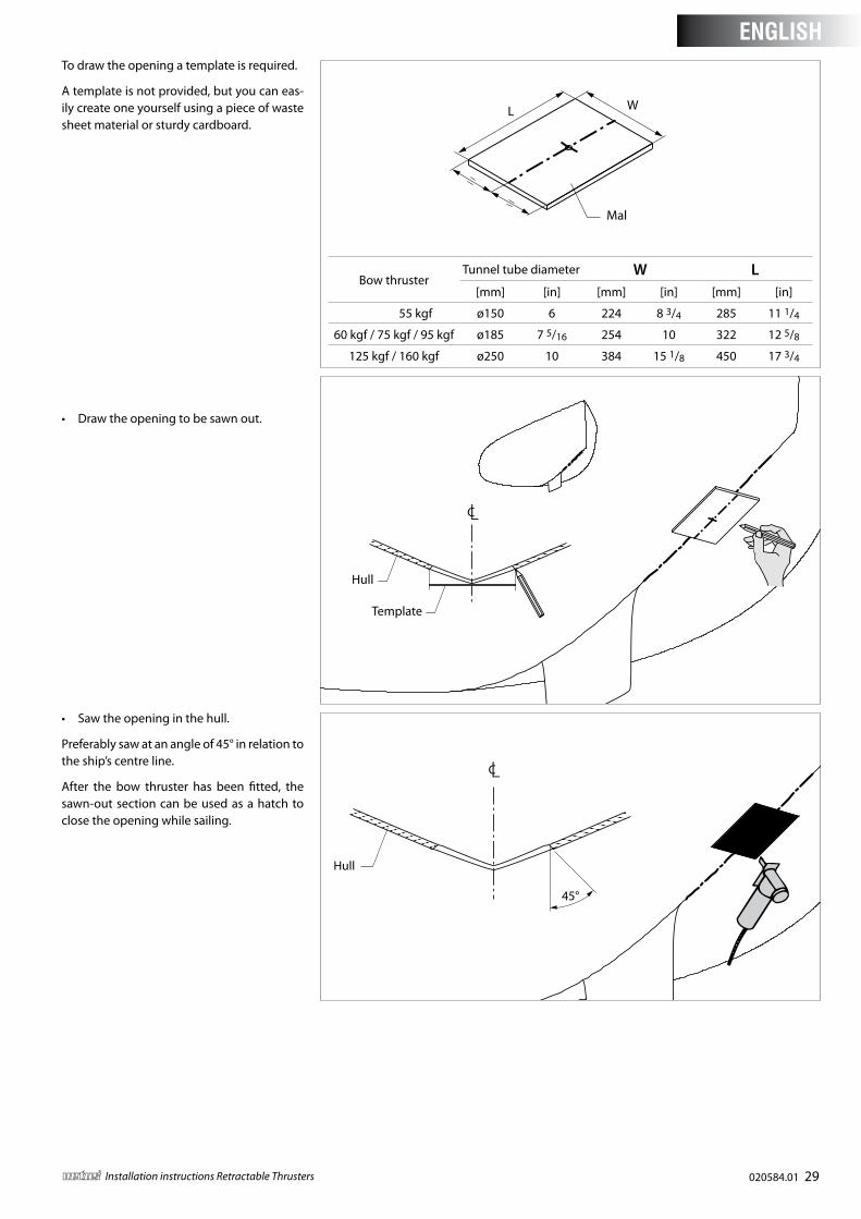
To draw the opening a template is required.
A template is not provided, but you can eas-ily create one yourself using a piece of waste sheet material or sturdy cardboard.
• Draw the opening to be sawn out.
• Saw the opening in the hull.
Preferably saw at an angle of 45° in relation to the ship’s centre line.
After the bow thruster has been fitted, the sawn-out section can be used as a hatch to close the opening while sailing.
L W
Mal
Hull
Template
45°
Hull
Bow thrusterTunnel tube diameter W L
[mm] [in] [mm] [in] [mm] [in]
35 kgf / 55 kgf ø150 6 224 8 3/4 285 11 1/4
60 kgf / 75 kgf / 95 kgf ø185 7 5/16 254 10 322 12 5/8
125 kgf / 160 kgf ø250 10 384 15 1/8 450 17 3/4
ENGLISH
30 020584.01 vetus® Installation instructions Retractable Thrusters
H
BOW
BOW
Max. 15 mm (5/8”)
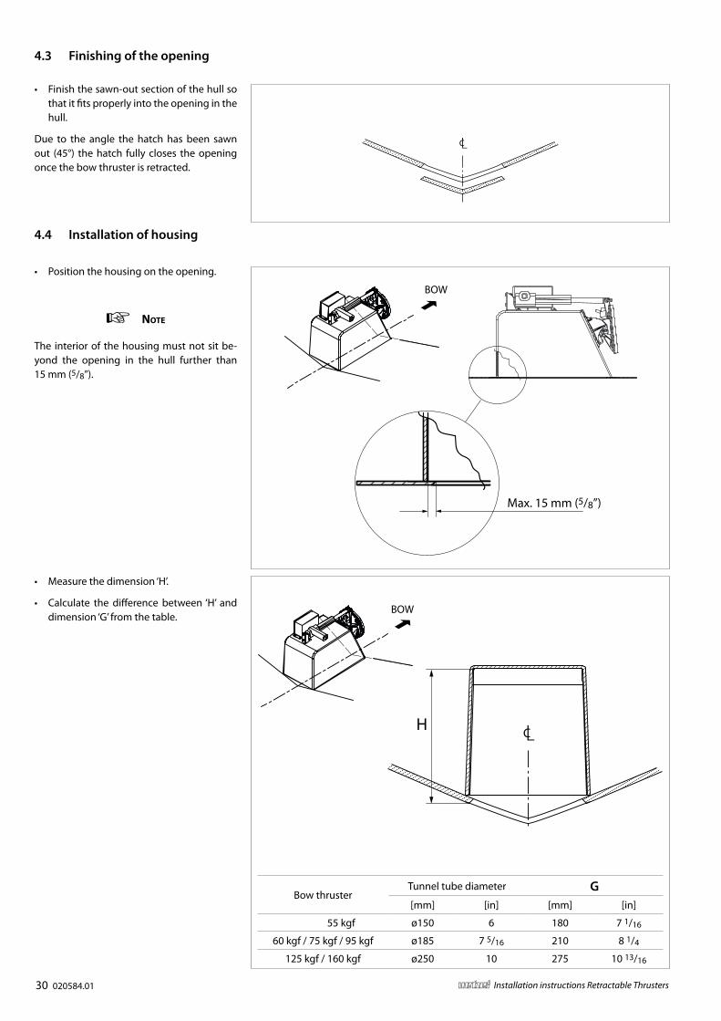
• Position the housing on the opening.
note
The interior of the housing must not sit be-yond the opening in the hull further than 15 mm (5/8”).
• Finish the sawn-out section of the hull so that it fits properly into the opening in the hull.
Due to the angle the hatch has been sawn out (45°) the hatch fully closes the opening once the bow thruster is retracted.
• Measure the dimension ‘H’.
• Calculate the difference between ‘H’ and dimension ‘G’ from the table.
Bow thrusterTunnel tube diameter G[mm] [in] [mm] [in]
35 kgf / 55 kgf ø150 6 180 7 1/16
60 kgf / 75 kgf / 95 kgf ø185 7 5/16 210 8 1/4
125 kgf / 160 kgf ø250 10 275 10 13/16
4 .3 Finishing of the opening
4 .4 Installation of housing
020584.01 31vetus® Installation instructions Retractable Thrusters
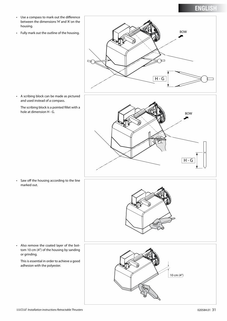
• Use a compass to mark out the difference between the dimensions ‘H’ and ‘A’ on the housing.
• Fully mark out the outline of the housing.
H - G
BOW
• Saw off the housing according to the line marked out.
• Also remove the coated layer of the bot-tom 10 cm (4”) of the housing by sanding or grinding.
This is essential in order to achieve a good adhesion with the polyester.
10 cm (4”)
• A scribing block can be made as pictured and used instead of a compass.
The scribing block is a pointed fillet with a hole at dimension H - G.
H - G
BOW
ENGLISH
32 020584.01 vetus® Installation instructions Retractable Thrusters
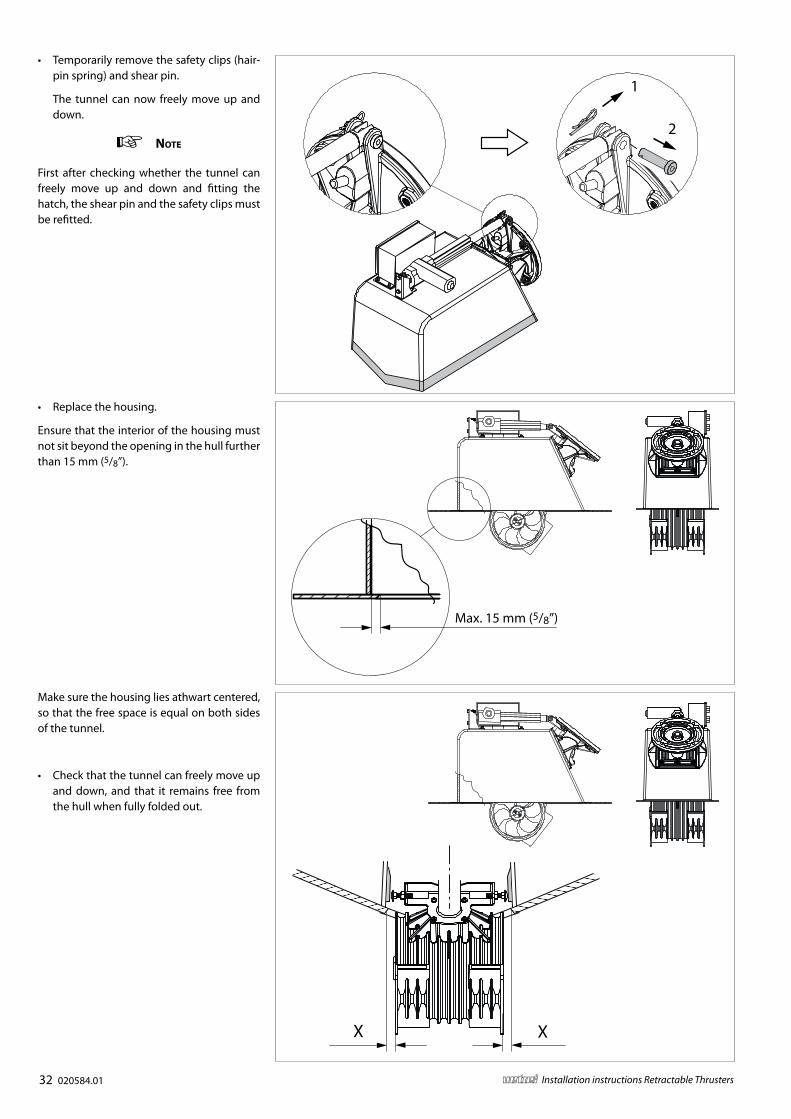
• Replace the housing.
Ensure that the interior of the housing must not sit beyond the opening in the hull further than 15 mm (5/8”).
Max. 15 mm (5/8”)
XX
Make sure the housing lies athwart centered, so that the free space is equal on both sides of the tunnel.
• Check that the tunnel can freely move up and down, and that it remains free from the hull when fully folded out.
• Temporarily remove the safety clips (hair-pin spring) and shear pin.
The tunnel can now freely move up and down.
note
First after checking whether the tunnel can freely move up and down and fitting the hatch, the shear pin and the safety clips must be refitted.
1
2
020584.01 33vetus® Installation instructions Retractable Thrusters
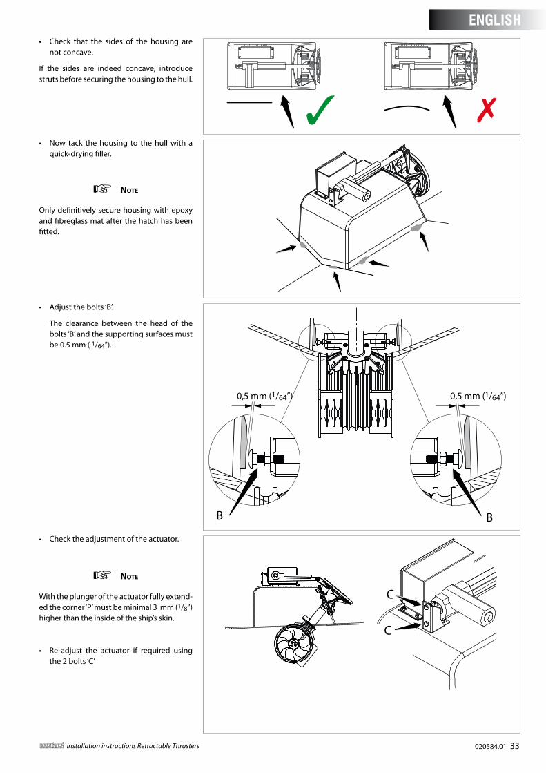
• Check that the sides of the housing are not concave.
If the sides are indeed concave, introduce struts before securing the housing to the hull.
• Now tack the housing to the hull with a quick-drying filler.
note
Only definitively secure housing with epoxy and fibreglass mat after the hatch has been fitted.
• Adjust the bolts ‘B’.
The clearance between the head of the bolts ‘B’ and the supporting surfaces must be 0.5 mm ( 1/64”).
BB
0,5 mm (1/64”)0,5 mm (1/64”)
• Check the adjustment of the actuator.
note
With the plunger of the actuator fully extend-ed the corner ‘P’ must be minimal 3 mm (1/8”) higher than the inside of the ship’s skin.
• Re-adjust the actuator if required using the 2 bolts ‘C’
C
C
ENGLISH
34 020584.01 vetus® Installation instructions Retractable Thrusters
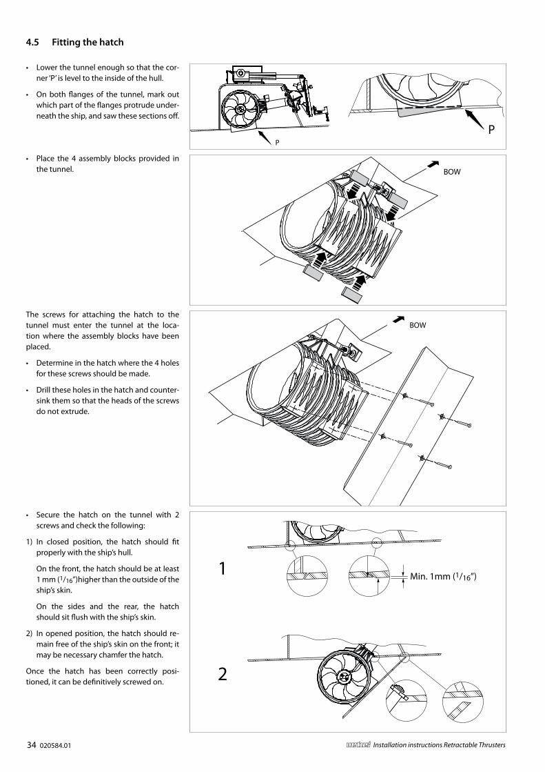
• Lower the tunnel enough so that the cor-ner ‘P’ is level to the inside of the hull.
• On both flanges of the tunnel, mark out which part of the flanges protrude under-neath the ship, and saw these sections off.
• Place the 4 assembly blocks provided in the tunnel.
PP
BOW
BOWThe screws for attaching the hatch to the tunnel must enter the tunnel at the loca-tion where the assembly blocks have been placed.
• Determine in the hatch where the 4 holes for these screws should be made.
• Drill these holes in the hatch and counter-sink them so that the heads of the screws do not extrude.
• Secure the hatch on the tunnel with 2 screws and check the following:
1) In closed position, the hatch should fit properly with the ship’s hull.
On the front, the hatch should be at least 1 mm (1/16”)higher than the outside of the ship’s skin.
On the sides and the rear, the hatch should sit flush with the ship’s skin.
2) In opened position, the hatch should re-main free of the ship’s skin on the front; it may be necessary chamfer the hatch.
Once the hatch has been correctly posi-tioned, it can be definitively screwed on.
Min. 1mm (1/16”)1
2
4 .5 Fitting the hatch
020584.01 35vetus® Installation instructions Retractable Thrusters
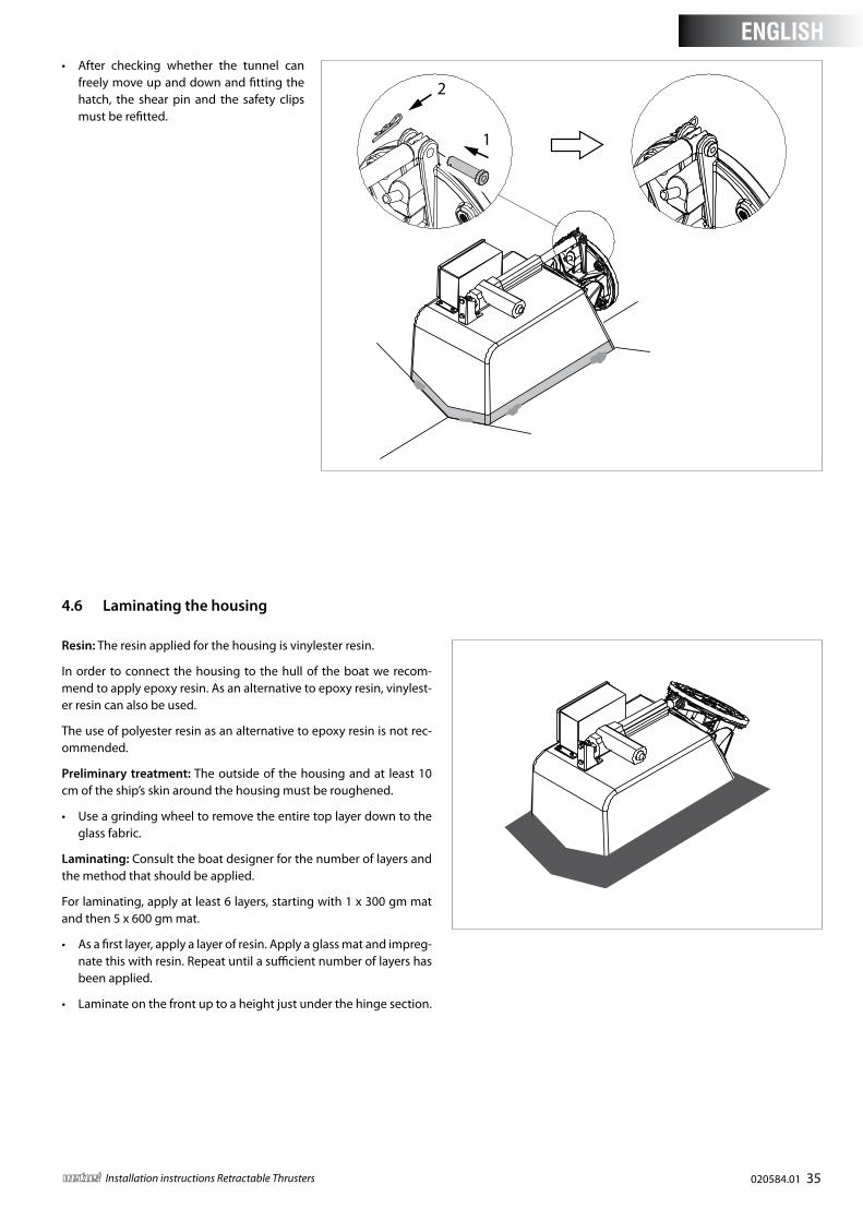
1
2• After checking whether the tunnel can
freely move up and down and fitting the hatch, the shear pin and the safety clips must be refitted.
4 .6 Laminating the housing
Resin: The resin applied for the housing is vinylester resin.
In order to connect the housing to the hull of the boat we recom-mend to apply epoxy resin. As an alternative to epoxy resin, vinylest-er resin can also be used.
The use of polyester resin as an alternative to epoxy resin is not rec-ommended.
Preliminary treatment: The outside of the housing and at least 10 cm of the ship’s skin around the housing must be roughened.
• Use a grinding wheel to remove the entire top layer down to the glass fabric.
Laminating: Consult the boat designer for the number of layers and the method that should be applied.
For laminating, apply at least 6 layers, starting with 1 x 300 gm mat and then 5 x 600 gm mat.
• As a first layer, apply a layer of resin. Apply a glass mat and impreg-nate this with resin. Repeat until a sufficient number of layers has been applied.
• Laminate on the front up to a height just under the hinge section.
ENGLISH
36 020584.01 vetus® Installation instructions Retractable Thrusters
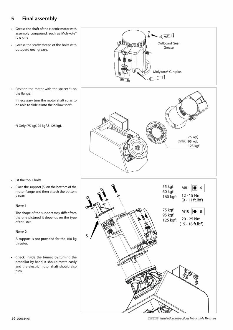
5 Final assembly
• Position the motor with the spacer *) on the flange.
If necessary turn the motor shaft so as to be able to slide it into the hollow shaft.
*) Only: 75 kgf, 95 kgf & 125 kgf.
• Fit the top 2 bolts.
• Place the support (S) on the bottom of the motor flange and then attach the bottom 2 bolts.
Note 1
The shape of the support may differ from the one pictured it depends on the type of thruster.
Note 2
A support is not provided for the 160 kg thruster.
• Check, inside the tunnel, by turning the propellor by hand; it should rotate easily and the electric motor shaft should also turn.
• Grease the shaft of the electric motor with assembly compound, such as Molykote® G-n plus.
• Grease the screw thread of the bolts with outboard gear grease.
Outboard GearGrease
Molykote® G-n plus
M8
12 - 15 Nm
6
M10
20 - 25 Nm
8
55 kgf:60 kgf:160 kgf:
75 kgf:95 kgf:125 kgf:
S
(9 - 11 ft.lbf )
(15 - 18 ft.lbf )
75 kgf,95 kgf,125 kgf
Only:
020584.01 37vetus® Installation instructions Retractable Thrusters
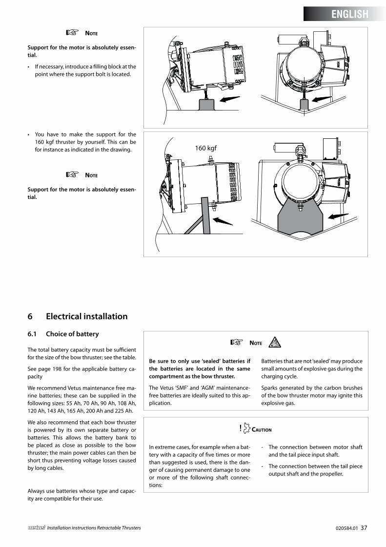
note
Support for the motor is absolutely essen-tial .
• If necessary, introduce a filling block at the point where the support bolt is located.
• You have to make the support for the 160 kgf thruster by yourself. This can be for instance as indicated in the drawing.
note
Support for the motor is absolutely essen-tial .
160 kgf
6 .1 Choice of battery
The total battery capacity must be sufficient for the size of the bow thruster; see the table.
See page 198 for the applicable battery ca-pacity
We recommend Vetus maintenance free ma-rine batteries; these can be supplied in the following sizes: 55 Ah, 70 Ah, 90 Ah, 108 Ah, 120 Ah, 143 Ah, 165 Ah, 200 Ah and 225 Ah.
We also recommend that each bow thruster is powered by its own separate battery or batteries. This allows the battery bank to be placed as close as possible to the bow thruster; the main power cables can then be short thus preventing voltage losses caused by long cables.
Always use batteries whose type and capac-ity are compatible for their use.
6 Electrical installation
note
Be sure to only use ‘sealed’ batteries if the batteries are located in the same compartment as the bow thruster .
The Vetus ‘SMF’ and ‘AGM’ maintenance-free batteries are ideally suited to this ap-plication.
Batteries that are not ‘sealed’ may produce small amounts of explosive gas during the charging cycle.
Sparks generated by the carbon brushes of the bow thruster motor may ignite this explosive gas.
Caution
In extreme cases, for example when a bat-tery with a capacity of five times or more than suggested is used, there is the dan-ger of causing permanent damage to one or more of the following shaft connec-tions:
- The connection between motor shaft and the tail piece input shaft.
- The connection between the tail piece output shaft and the propeller.
ENGLISH
38 020584.01 vetus® Installation instructions Retractable Thrusters
6 .2 Main power cables (battery cables)
The minimum diameter must be sufficient for the bow thruster in use and the voltage drop must not be more than 10% of the voltage supplied, consult the table on page 199.
note
The maximum operating time and the thrust, as specified by the technical de-tails in your bow thruster installation and operating manual, are based on the recommended storage battery capaci-ties and storage battery connection ca-bles .
If considerably larger batteries in combi-nation with very short connection cables with considerably larger diameter than recommended are used then the thrust will increase . In such cases the maximum operating time must be reduced in order to prevent damage to the motor .
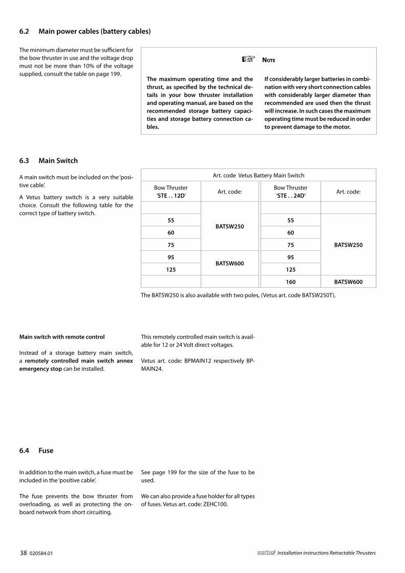
6 .3 Main Switch
A main switch must be included on the ‘posi-tive cable’.
A Vetus battery switch is a very suitable choice. Consult the following table for the correct type of battery switch.
Art. code Vetus Battery Main Switch
Bow Thruster‘STE . . 12D’
Art. code:Bow Thruster‘STE . . 24D’
Art. code:
35
BATSW25055 55
BATSW250
60 60
75 75
95BATSW600
95
125 125
160 BATSW600
The BATSW250 is also available with two poles, (Vetus art. code BATSW250T).
6 .4 Fuse
In addition to the main switch, a fuse must be included in the ‘positive cable’.
The fuse prevents the bow thruster from overloading, as well as protecting the on-board network from short circuiting.
See page 199 for the size of the fuse to be used.
We can also provide a fuse holder for all types of fuses. Vetus art. code: ZEHC100.
Main switch with remote control
Instead of a storage battery main switch, a remotely controlled main switch annex emergency stop can be installed.
This remotely controlled main switch is avail-able for 12 or 24 Volt direct voltages.
Vetus art. code: BPMAIN12 respectively BP-MAIN24.
020584.01 39vetus® Installation instructions Retractable Thrusters
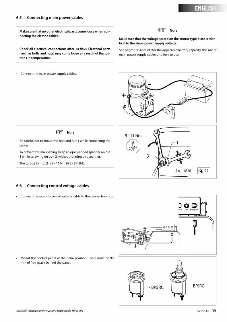
6 .5 Connecting main power cables
note
Be careful not to rotate the bolt and nut 1 while connecting the cables.
To prevent this happening, keep an open-ended spanner on nut 1 while screwing on bolt 2, without rotating this spanner.
The torque for nut 2 is 9 - 11 Nm (6.5 - 8 ft.lbf ).
• Mount the control panel at the helm position. There must be 90 mm of free space behind the panel.
• Connect the main power supply cables.
- BPSRC - BPJRC
9 - 11 Nm
17
1
2
2 x M10
Make sure that no other electrical parts come loose when con-necting the electric cables .
Check all electrical connections after 14 days . Electrical parts (such as bolts and nuts) may come loose as a result of fluctua-tions in temperature .
note
Make sure that the voltage stated on the motor type plate is iden-tical to the ship’s power supply voltage .
See pages 198 and 199 for the applicable battery capacity, the size of main power supply cables and fuse to use.
6 .6 Connecting control voltage cables
• Connect the motor’s control voltage cable to the connection box.
AUX OUT AUX IN CAN MOTOR
AUX IN CAN MOTOR
ENGLISH
40 020584.01 vetus® Installation instructions Retractable Thrusters
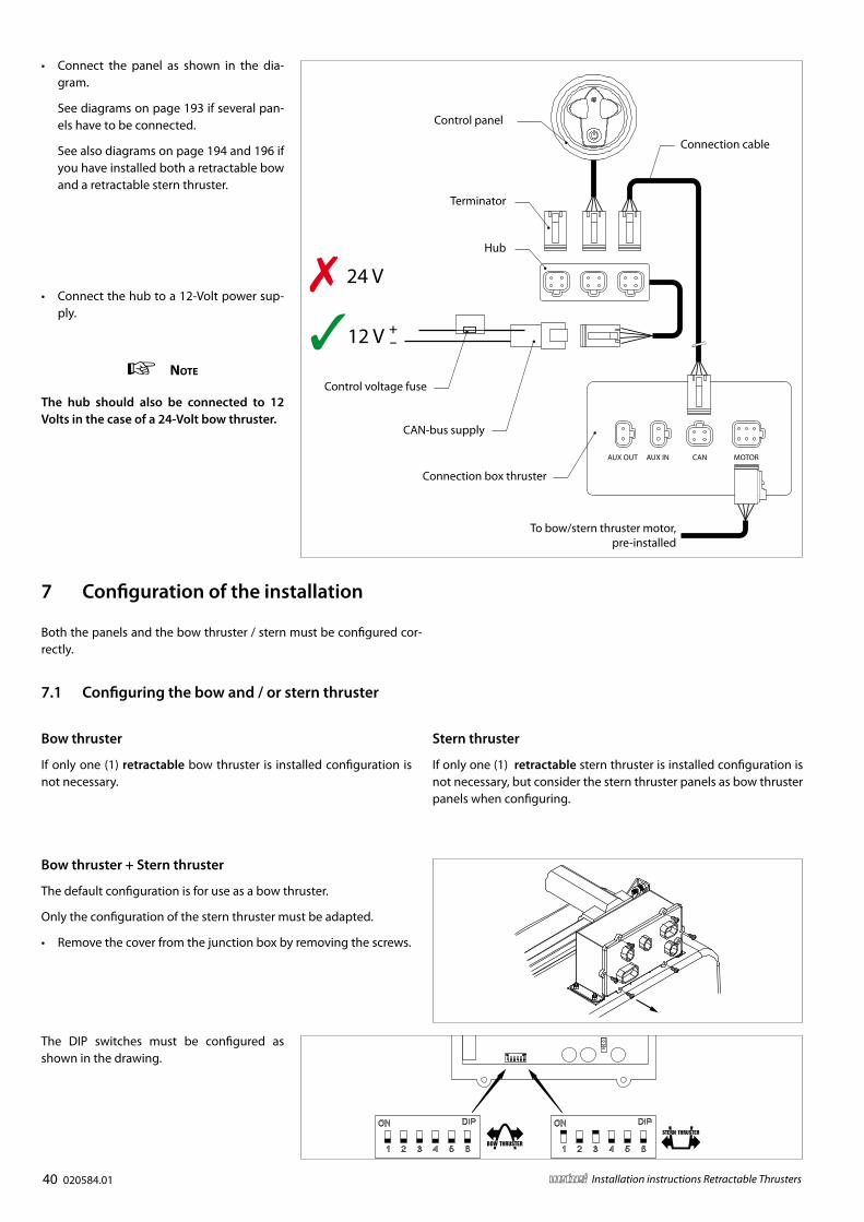
• Connect the panel as shown in the dia-gram.
See diagrams on page 193 if several pan-els have to be connected.
See also diagrams on page 194 and 196 if you have installed both a retractable bow and a retractable stern thruster.
AUX OUT AUX IN CAN MOTOR
+–12 V
24 V
Control panel
Connection cable
Control voltage fuse
CAN-bus supply
Terminator
Hub
Connection box thruster
To bow/stern thruster motor,pre-installed
• Connect the hub to a 12-Volt power sup-ply.
note
The hub should also be connected to 12 Volts in the case of a 24-Volt bow thruster .
7 Configuration of the installation
Both the panels and the bow thruster / stern must be configured cor-rectly.
7 .1 Configuring the bow and / or stern thruster
The DIP switches must be configured as shown in the drawing.
Bow thruster
If only one (1) retractable bow thruster is installed configuration is not necessary.
Stern thruster
If only one (1) retractable stern thruster is installed configuration is not necessary, but consider the stern thruster panels as bow thruster panels when configuring.
Bow thruster + Stern thruster
The default configuration is for use as a bow thruster.
Only the configuration of the stern thruster must be adapted.
• Remove the cover from the junction box by removing the screws.
020584.01 41vetus® Installation instructions Retractable Thrusters
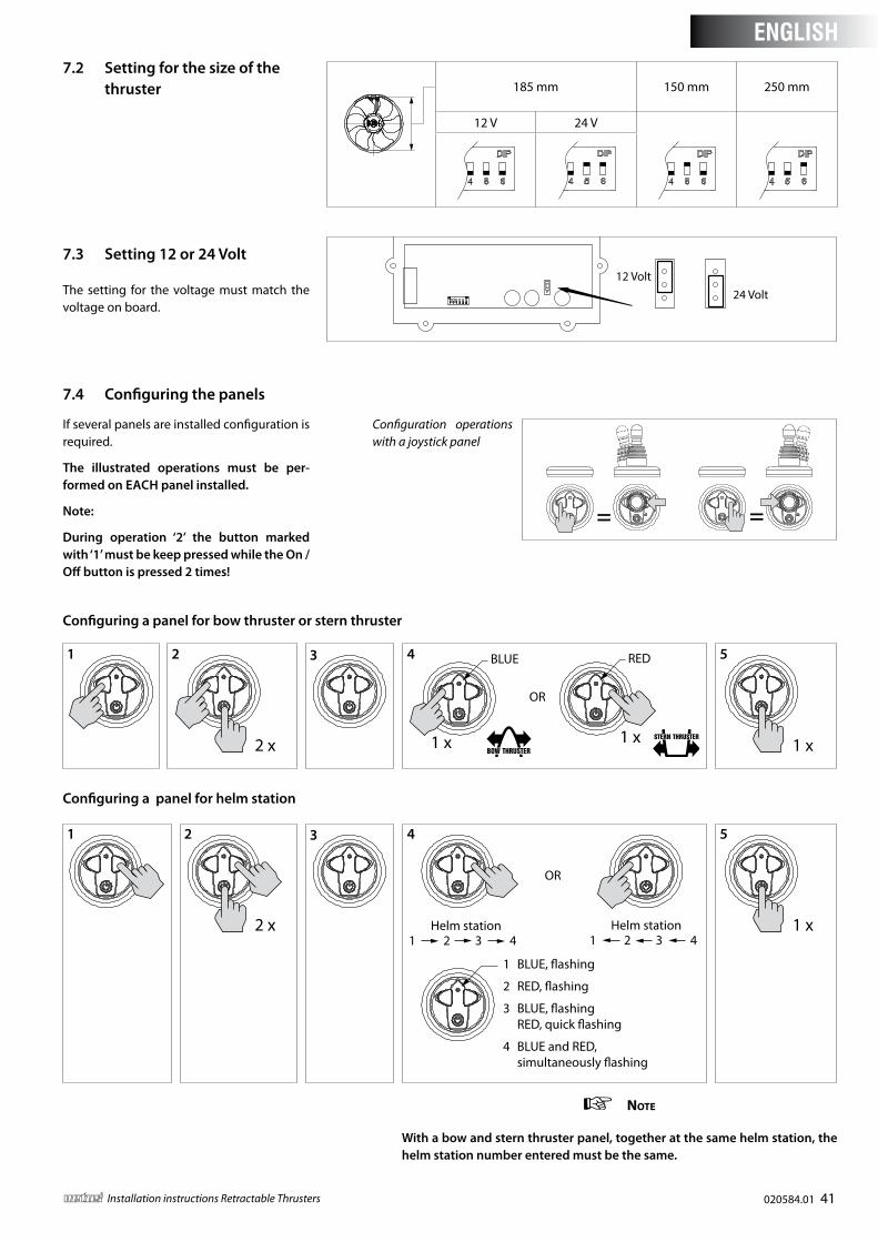
7 .4 Configuring the panels
7 .3 Setting 12 or 24 Volt
The setting for the voltage must match the voltage on board.
12 Volt24 Volt
If several panels are installed configuration is required.
The illustrated operations must be per-formed on EACH panel installed .
Note:
During operation ‘2’ the button marked with ‘1’ must be keep pressed while the On / Off button is pressed 2 times!
= =
2 x 1 x 1 x
BLUE RED
OR
1 x
Configuration operations with a joystick panel
Configuring a panel for bow thruster or stern thruster
Configuring a panel for helm station
1 2 3 4 5
2 x
OR
Helm station1 2 3 4
Helm station1 2 3 4
1 BLUE, �ashing
2 RED, �ashing
3 BLUE, �ashing RED, quick �ashing
4 BLUE and RED, simultaneously �ashing
1 x
1 2 3 4 5
note
With a bow and stern thruster panel, together at the same helm station, the helm station number entered must be the same .
7 .2 Setting for the size of the thruster 185 mm 150 mm 250 mm
12 V 24 V
ENGLISH
42 020584.01 vetus® Installation instructions Retractable Thrusters
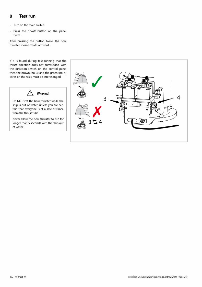
3 4
3 4
• Turn on the main switch.
• Press the on/off button on the panel twice.
After pressing the button twice, the bow thruster should rotate outward.
8 Test run
If it is found during test running that the thrust direction does not correspond with the direction switch on the control panel then the brown (no. 3) and the green (no. 4) wires on the relay must be interchanged.
Warning!
Do NOT test the bow thruster while the ship is out of water, unless you are cer-tain that everyone is at a safe distance from the thrust tube.
Never allow the bow thruster to run for longer than 5 seconds with the ship out of water.
020584.01 187vetus® Installation instructions Retractable Thrusters
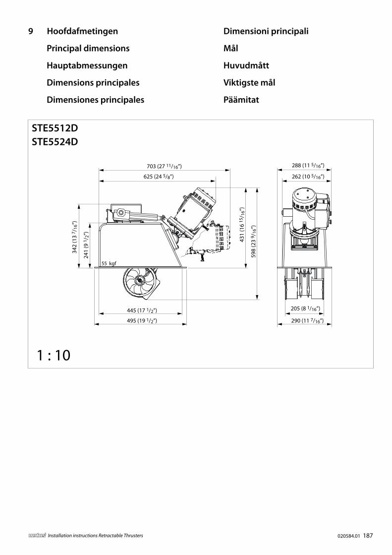
625 (24 5/8”)
703 (27 11/16”)
445 (17 1/2”)
495 (19 1/2”)
342
(13
7 /16
”)
241
(9 1
/ 2”)
290 (11 7/16”)
262 (10 5/16”)
431
(16
15/ 1
6”)
598
(23
9 /16
”)
205 (8 1/16”)
288 (11 5/16”)
55 kgf
STE5512DSTE5524D
1 : 10
Principal dimensions
Hauptabmessungen
Dimensions principales
Dimensiones principales
Dimensioni principali
Mål
Huvudmått
Viktigste mål
Päämitat
9 Hoofdafmetingen
188 020584.01 vetus® Installation instructions Retractable Thrusters
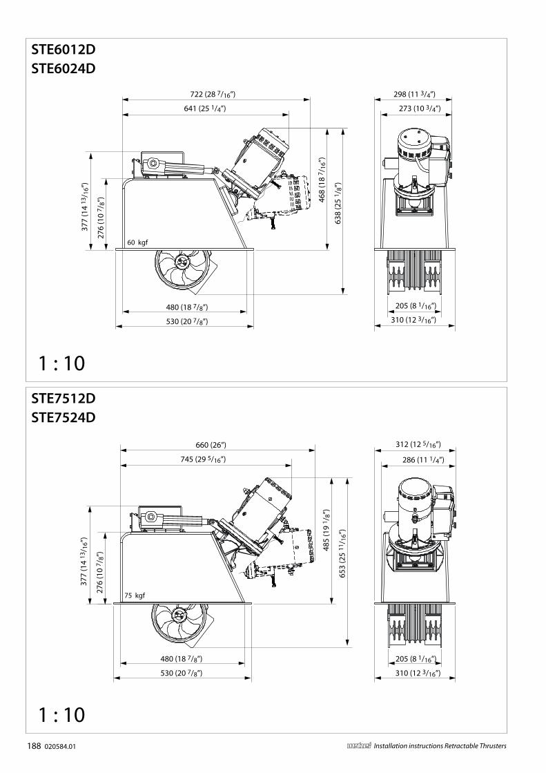
75 kgf
205 (8 1/16”)480 (18 7/8”)
530 (20 7/8”)
377
(14
13/ 1
6”)
276
(10
7 /8”
)
745 (29 5/16”)
660 (26”)
485
(19
1 /8”
)
653
(25
11/ 1
6”)
310 (12 3/16”)
286 (11 1/4”)
312 (12 5/16”)
STE7512DSTE7524D
377
(14
13/ 1
6”)
276
(10
7 /8”
)
480 (18 7/8”)
530 (20 7/8”)
298 (11 3/4”)
205 (8 1/16”)
641 (25 1/4”)
722 (28 7/16”)
468
(18
7 /16
”)
638
(25
1 /8”
)
273 (10 3/4”)
310 (12 3/16”)
60 kgf
1 : 10
1 : 10
STE6012DSTE6024D
020584.01 189vetus® Installation instructions Retractable Thrusters
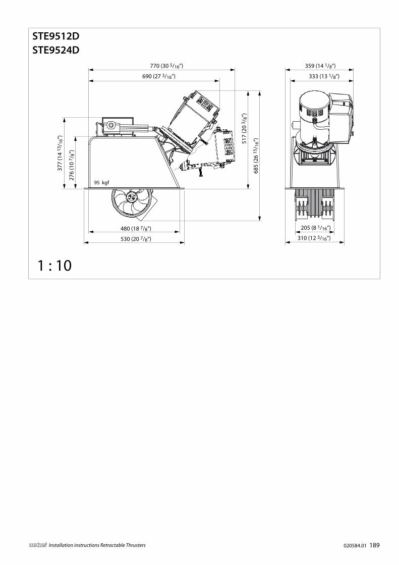
95 kgf
359 (14 1/8”)
205 (8 1/16”)
333 (13 1/8”)
310 (12 3/16”)
377
(14
13/ 1
6”)
276
(10
7 /8”
)
480 (18 7/8”)
530 (20 7/8”)51
7 (2
0 3 /
8”)
685
(26
15/ 1
6”)
690 (27 3/16”)
770 (30 5/16”)
1 : 10
STE9512DSTE9524D
190 020584.01 vetus® Installation instructions Retractable Thrusters
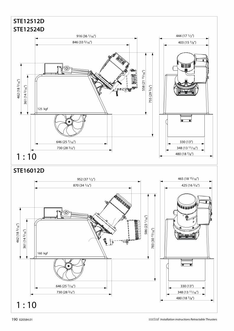
125 kgf
330 (13”)646 (25 7/16”)
730 (28 3/4”) 348 (13 11/16”)55
8 (2
1 15
/ 16”
)
755
(29
3 /4”
)
462
(18
3 /16
”)
361
(14
3 /16
”)
846 (33 5/16”)
916 (36 1/16”)
403 (15 7/8”)
444 (17 1/2”)
480 (18 7/8”)
STE12512DSTE12524D
1 : 10
160 kgf
330 (13”)646 (25 7/16”)
730 (28 3/4”) 348 (13 11/16”)
480 (18 7/8”)
462
(18
3 /16
”)
361
(14
3 /16
”)
586
(23
1 /16
”)
783
(30
13/ 1
6”)
870 (34 1/4”)
952 (37 1/2”)
425 (16 3/4”)
465 (18 15/16”)
1 : 10
STE16012D
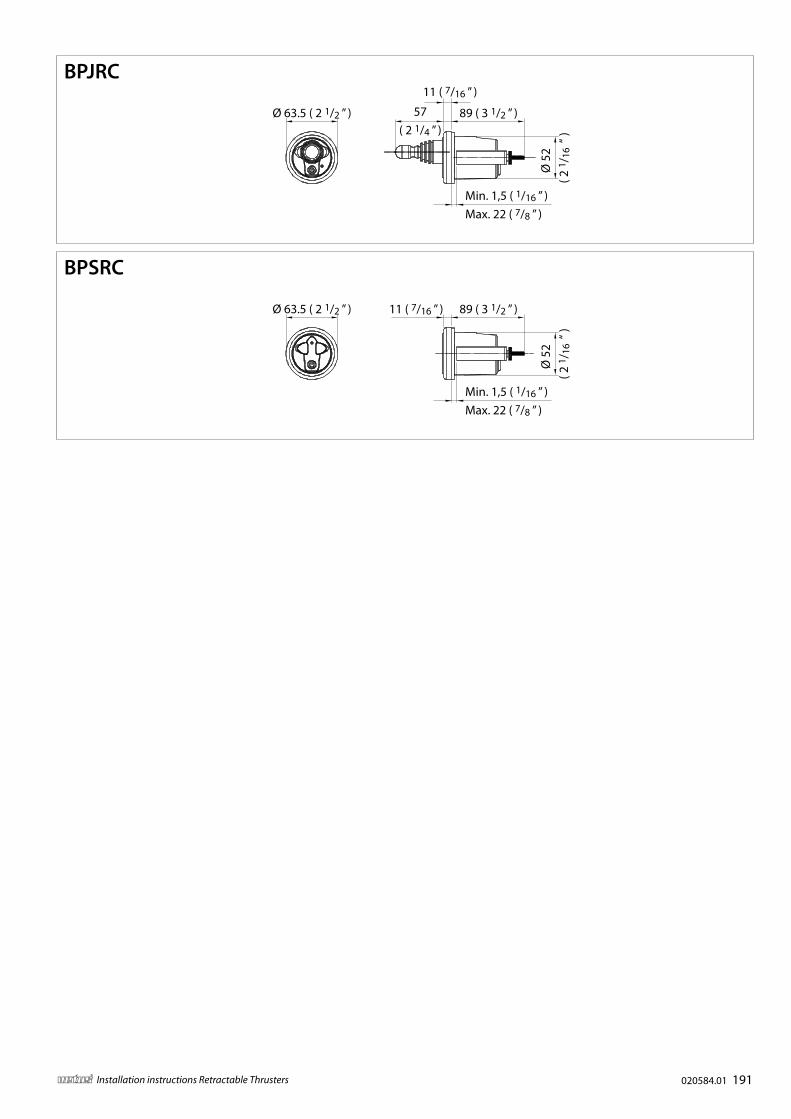
020584.01 191vetus® Installation instructions Retractable Thrusters
Min. 1,5 ( 1/16 ” )Max. 22 ( 7/8 ” )
Ø 5
2
( 2 1
/ 16
“ )
89 ( 3 1/2 ” )11 ( 7/16 ” )Ø 63.5 ( 2 1/2 ” )
57( 2 1/4 ” )
Min. 1,5 ( 1/16 ” )Max. 22 ( 7/8 ” )
Ø 5
2
( 2 1
/ 16
“ )
89 ( 3 1/2 ” )
11 ( 7/16 ” )
Ø 63.5 ( 2 1/2 ” )
BPJRC
BPSRC
192 020584.01 vetus® Installation instructions Retractable Thrusters
AUX OUT AUX IN CAN MOTOR
+–12 V
5 6
4
3
71
2
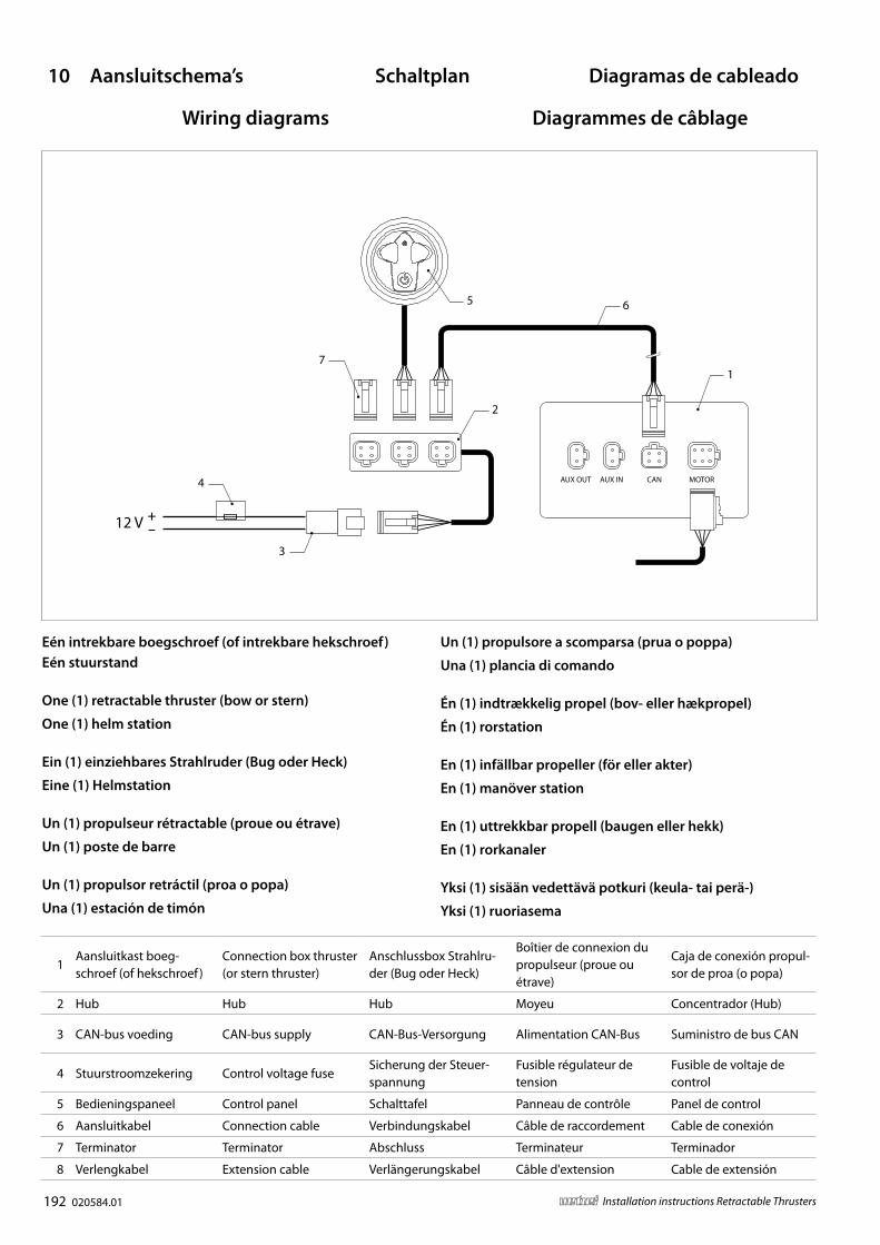
Eén intrekbare boegschroef (of intrekbare hekschroef) Eén stuurstand
One (1) retractable thruster (bow or stern)
One (1) helm station
Ein (1) einziehbares Strahlruder (Bug oder Heck)
Eine (1) Helmstation
Un (1) propulseur rétractable (proue ou étrave)
Un (1) poste de barre
Un (1) propulsor retráctil (proa o popa)
Una (1) estación de timón
Un (1) propulsore a scomparsa (prua o poppa)
Una (1) plancia di comando
Én (1) indtrækkelig propel (bov- eller hækpropel)
Én (1) rorstation
En (1) infällbar propeller (för eller akter)
En (1) manöver station
En (1) uttrekkbar propell (baugen eller hekk)
En (1) rorkanaler
Yksi (1) sisään vedettävä potkuri (keula- tai perä-)
Yksi (1) ruoriasema
1Aansluitkast boeg-schroef (of hekschroef )
Connection box thruster (or stern thruster)
Anschlussbox Strahlru-der (Bug oder Heck)
Boîtier de connexion du propulseur (proue ou étrave)
Caja de conexión propul-sor de proa (o popa)
1Scatola di connessione del propulsore (o pro-pulsore di poppa)
Propellens klemkasse (eller hækpropel)
Anslutningsbox propel-ler (eller akterpropeller)
Tilkoblingsboks for pro-pell (eller hekkthruster)
Potkurin (tai peräpotku-rin) liitäntärasia
2 Hub Hub Hub Moyeu Concentrador (Hub) 2 Mozzo Nav Hubb Hub Keskitin
3 CAN-bus voeding CAN-bus supply CAN-Bus-Versorgung Alimentation CAN-Bus Suministro de bus CAN 3CAN-bus di alimenta-zione
CAN-busforsyning CAN-bus tillförsel CAN-bus tilførsel CAN-väylän syöttö
4 Stuurstroomzekering Control voltage fuseSicherung der Steuer-spannung
Fusible régulateur de tension
Fusible de voltaje de control
4Fusibile della tensione di comando
StyrespændingssikringKontroll spänning säkring
Sikringskontroll for spenning
Ohjausjännitteen sulake
5 Bedieningspaneel Control panel Schalttafel Panneau de contrôle Panel de control 5 Pannello di controllo Betjeningspanel Kontrollpanel Kontrollpanel Ohjauspaneeli
6 Aansluitkabel Connection cable Verbindungskabel Câble de raccordement Cable de conexión 6 Cavo di connessione Tilslutningskabel Anslutningskabel Tilkoblingskabel Kytkentäkaapeli
7 Terminator Terminator Abschluss Terminateur Terminador 7 Terminatore Impedansmodstand Terminator Terminator Terminaattori
8 Verlengkabel Extension cable Verlängerungskabel Câble d'extension Cable de extensión 8 Cavo di prolunga Forlængerkabel Förlängningssladd Skjøteledning Jatkojohto
10 Aansluitschema’s Schaltplan Diagramas de cableado Schemi Elettrici Kopplingsscheman Kytkentäkaaviot
Wiring diagrams Diagrammes de câblage Strømskemaer Koblingsskjemaer

020584.01 193vetus® Installation instructions Retractable Thrusters
AUX OUT AUX IN CAN MOTOR
+–12 V
56
4
3
71
22
58
Eén intrekbare boegschroef (of intrekbare hekschroef)
Twee stuurstanden
One (1) retractable thruster (bow or stern)
Two (2) helm stations
Ein (1) einziehbares Strahlruder (Bug oder Heck)
Zwei (2) Helmstationen
Un (1) propulseur rétractable (proue ou étrave)
Deux (2) postes de barre
Un (1) propulsor retráctil (proa o popa)
Dos (2) estaciones de timón
Un (1) propulsore a scomparsa (prua o poppa)
Due (2) plance di comando
Én (1) indtrækkelig propel (bov- eller hækpropel)
To (2) rorstationer
En (1) infällbar propeller (bog eller akter)
Två (2) manöverstationer
En (1) uttrekkbar propell (baugen eller hekk)
To (2) rorkanaler
Yksi (1) sisään vedettävä potkuri (keula- tai perä-)
Kaksi (2) ruoriasemaa
1Aansluitkast boeg-schroef (of hekschroef )
Connection box thruster (or stern thruster)
Anschlussbox Strahlru-der (Bug oder Heck)
Boîtier de connexion du propulseur (proue ou étrave)
Caja de conexión propul-sor de proa (o popa)
1Scatola di connessione del propulsore (o pro-pulsore di poppa)
Propellens klemkasse (eller hækpropel)
Anslutningsbox propel-ler (eller akterpropeller)
Tilkoblingsboks for pro-pell (eller hekkthruster)
Potkurin (tai peräpotku-rin) liitäntärasia
2 Hub Hub Hub Moyeu Concentrador (Hub) 2 Mozzo Nav Hubb Hub Keskitin
3 CAN-bus voeding CAN-bus supply CAN-Bus-Versorgung Alimentation CAN-Bus Suministro de bus CAN 3CAN-bus di alimenta-zione
CAN-busforsyning CAN-bus tillförsel CAN-bus tilførsel CAN-väylän syöttö
4 Stuurstroomzekering Control voltage fuseSicherung der Steuer-spannung
Fusible régulateur de tension
Fusible de voltaje de control
4Fusibile della tensione di comando
StyrespændingssikringKontroll spänning säkring
Sikringskontroll for spenning
Ohjausjännitteen sulake
5 Bedieningspaneel Control panel Schalttafel Panneau de contrôle Panel de control 5 Pannello di controllo Betjeningspanel Kontrollpanel Kontrollpanel Ohjauspaneeli
6 Aansluitkabel Connection cable Verbindungskabel Câble de raccordement Cable de conexión 6 Cavo di connessione Tilslutningskabel Anslutningskabel Tilkoblingskabel Kytkentäkaapeli
7 Terminator Terminator Abschluss Terminateur Terminador 7 Terminatore Impedansmodstand Terminator Terminator Terminaattori
8 Verlengkabel Extension cable Verlängerungskabel Câble d'extension Cable de extensión 8 Cavo di prolunga Forlængerkabel Förlängningssladd Skjøteledning Jatkojohto
10 Aansluitschema’s Schaltplan Diagramas de cableado Schemi Elettrici Kopplingsscheman Kytkentäkaaviot
Wiring diagrams Diagrammes de câblage Strømskemaer Koblingsskjemaer
194 020584.01 vetus® Installation instructions Retractable Thrusters
AUX OUT AUX IN CAN MOTOR
AUX OUT AUX IN CAN MOTOR
+–12 V
5
6
4
3
79
22
10
6
1
1Aansluitkast boeg-schroef
Connection box bow thruster
Verbindungsbox von Bugstrahlruder
Boîtier de connexion du propulseur à étrave
Caja de conexión propul-sor de proa
1Scatola di connessione del propulsore di prua
Bovpropellens klem-kasse
Kopplingsbox bogpro-peller
Koblingsboks for baug-propell
Keulapotkurin liitäntärasia
2 Hub Hub Hub Moyeu Concentrador (Hub) 2 Scafo Nav Hubb Hub Keskitin
3 CAN-bus voeding CAN-bus supply CAN-Bus-Versorgung Alimentation CAN-busAlimentación del CAN-bus
3 Alimentazione CAN-bus CAN-busforsyning CAN-bus tillförsel CAN-bus tilførsel CAN-väylän syöttö
4 Stuurstroomzekering Control voltage fuse Steuerstrom SicherungFusible régulateur de tension
Fusible de tensión de control
4Fusibile della tensione di comando
StyrespændingssikringKontroll spänning säkring
Sikringskontroll for spenning
Ohjausjännitteen sulake
5Bedieningspaneel boegschroef
Control panel bow thruster
Bedienfeld von Bug-strahlruder
Panneau de commandes du propulseur d'étrave
Panel de control propul-sor de proa
5Pannello di controllo del propulsore di prua
Betjeningspanel til bovpropel
Kontrollpanel bogpro-peller
Kontrollpanel for baug-propell
Keulapotkurin ohjauspa-neeli
6 Aansluitkabel Connection cable Verbindungskabel Câble de raccordement Cable de conexión 6 Cavo di collegamento Tilslutningskabel Anslutningskabel Tilkoblingskabel Kytkentäkaapeli
7 Terminator Terminator Abschluss Terminateur Terminador 7 Terminatore Impedansmodstand Terminator Terminator Terminaattori
8 Verlengkabel Extension cable Verlängerungskabel Câble d'extension Cable de extensión 8 Cavo di prolunga Forlængerkabel Förlängningssladd Skjøteledning Jatkojohto
9 Aansluitkast hekschroefConnection box stern thruster
Verbindungsbox Heck-strahlruder
Boîtier de connexion du propulseur de proue
Caja de conexión propul-sor de popa
9Scatola di connessione del propulsore di poppa
Hækpropellens klem-kasse
Kopplingsbox akterpro-peller
Koblingsboks for hekkthruster
Peräpotkurin liitäntärasia
10Bedieningspaneel hekschroef
Control panel stern thruster
Bedienfeld von Heck-strahlruder
Panneau de commandes du propulseur de proue
Panel de control propul-sor de popa
10Pannello di controllo del propulsore di poppa
Betjeningspanel til hækpropel
Kontrollpanel akterpro-peller
Kontrollpanel for hekkthruster
Peräpotkurin ohjauspa-neeli
020584.01 195vetus® Installation instructions Retractable Thrusters
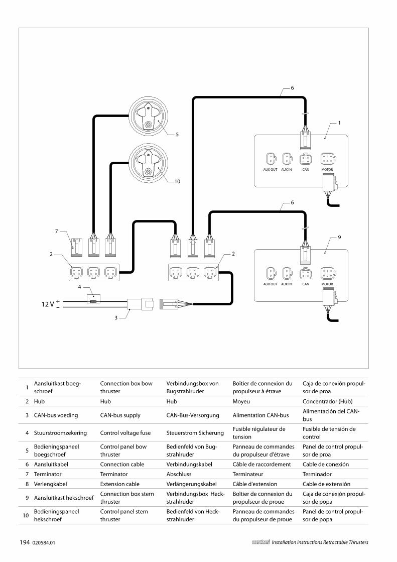
Intrekbare boegschroef EN intrekbare hekschroef
Eén stuurstand
Retractable thrusters (bow AND stern)
One (1) helm station
Einziehbare Strahlruder (Bug UND Heck)
Eine (1) Helmstation
Propulseurs rétractables (proue OU étrave)
Un (1) poste de barre
Propulsores retráctiles (proa Y popa)
Una (1) estación de timón
Propulsori a scomparsa (prua E poppa)
Una (1) plancia di comando
Indtrækkelige propeller (bov- OG hækpropel)
Én (1) rorstation
Infällbar propeller (bog OCH akter)
En (1) manöverstation
Uttrekkbar propeller (baug OG hekk)
En (1) rorkanaler
Sisään vedettävät potkurit (keula- JA perä-)
Yksi (1) ruoriasema
1Aansluitkast boeg-schroef
Connection box bow thruster
Verbindungsbox von Bugstrahlruder
Boîtier de connexion du propulseur à étrave
Caja de conexión propul-sor de proa
1Scatola di connessione del propulsore di prua
Bovpropellens klem-kasse
Kopplingsbox bogpro-peller
Koblingsboks for baug-propell
Keulapotkurin liitäntärasia
2 Hub Hub Hub Moyeu Concentrador (Hub) 2 Scafo Nav Hubb Hub Keskitin
3 CAN-bus voeding CAN-bus supply CAN-Bus-Versorgung Alimentation CAN-busAlimentación del CAN-bus
3 Alimentazione CAN-bus CAN-busforsyning CAN-bus tillförsel CAN-bus tilførsel CAN-väylän syöttö
4 Stuurstroomzekering Control voltage fuse Steuerstrom SicherungFusible régulateur de tension
Fusible de tensión de control
4Fusibile della tensione di comando
StyrespændingssikringKontroll spänning säkring
Sikringskontroll for spenning
Ohjausjännitteen sulake
5Bedieningspaneel boegschroef
Control panel bow thruster
Bedienfeld von Bug-strahlruder
Panneau de commandes du propulseur d'étrave
Panel de control propul-sor de proa
5Pannello di controllo del propulsore di prua
Betjeningspanel til bovpropel
Kontrollpanel bogpro-peller
Kontrollpanel for baug-propell
Keulapotkurin ohjauspa-neeli
6 Aansluitkabel Connection cable Verbindungskabel Câble de raccordement Cable de conexión 6 Cavo di collegamento Tilslutningskabel Anslutningskabel Tilkoblingskabel Kytkentäkaapeli
7 Terminator Terminator Abschluss Terminateur Terminador 7 Terminatore Impedansmodstand Terminator Terminator Terminaattori
8 Verlengkabel Extension cable Verlängerungskabel Câble d'extension Cable de extensión 8 Cavo di prolunga Forlængerkabel Förlängningssladd Skjøteledning Jatkojohto
9 Aansluitkast hekschroefConnection box stern thruster
Verbindungsbox Heck-strahlruder
Boîtier de connexion du propulseur de proue
Caja de conexión propul-sor de popa
9Scatola di connessione del propulsore di poppa
Hækpropellens klem-kasse
Kopplingsbox akterpro-peller
Koblingsboks for hekkthruster
Peräpotkurin liitäntärasia
10Bedieningspaneel hekschroef
Control panel stern thruster
Bedienfeld von Heck-strahlruder
Panneau de commandes du propulseur de proue
Panel de control propul-sor de popa
10Pannello di controllo del propulsore di poppa
Betjeningspanel til hækpropel
Kontrollpanel akterpro-peller
Kontrollpanel for hekkthruster
Peräpotkurin ohjauspa-neeli
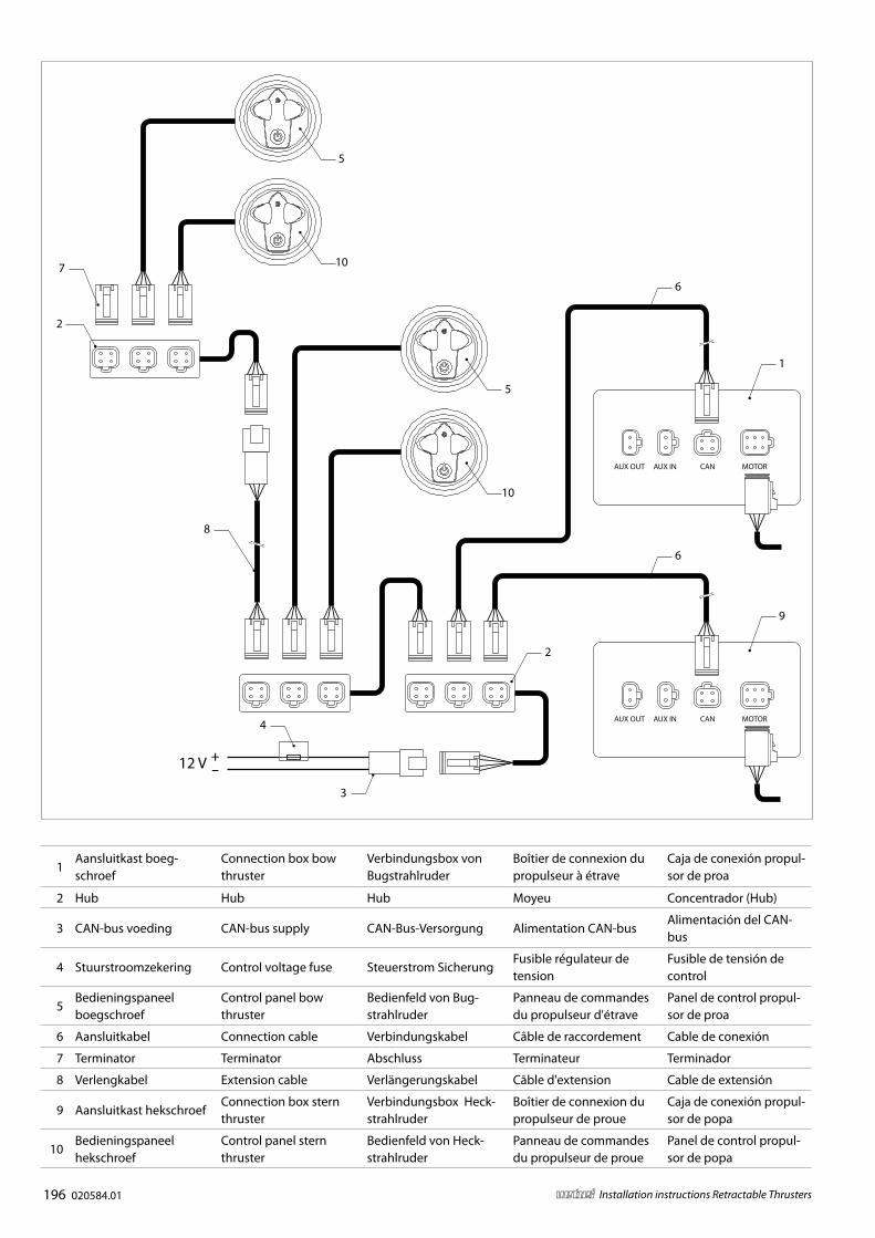
196 020584.01 vetus® Installation instructions Retractable Thrusters
AUX OUT AUX IN CAN MOTOR
AUX OUT AUX IN CAN MOTOR
+–12 V
5
6
4
3
9
2
10
6
1
7
2
5
10
8
1Aansluitkast boeg-schroef
Connection box bow thruster
Verbindungsbox von Bugstrahlruder
Boîtier de connexion du propulseur à étrave
Caja de conexión propul-sor de proa
1Scatola di connessione del propulsore di prua
Bovpropellens klem-kasse
Kopplingsbox bogpro-peller
Koblingsboks for baug-propell
Keulapotkurin liitäntärasia
2 Hub Hub Hub Moyeu Concentrador (Hub) 2 Scafo Nav Hubb Hub Keskitin
3 CAN-bus voeding CAN-bus supply CAN-Bus-Versorgung Alimentation CAN-busAlimentación del CAN-bus
3 Alimentazione CAN-bus CAN-busforsyning CAN-bus tillförsel CAN-bus tilførsel CAN-väylän syöttö
4 Stuurstroomzekering Control voltage fuse Steuerstrom SicherungFusible régulateur de tension
Fusible de tensión de control
4Fusibile della tensione di comando
StyrespændingssikringKontroll spänning säkring
Sikringskontroll for spenning
Ohjausjännitteen sulake
5Bedieningspaneel boegschroef
Control panel bow thruster
Bedienfeld von Bug-strahlruder
Panneau de commandes du propulseur d'étrave
Panel de control propul-sor de proa
5Pannello di controllo del propulsore di prua
Betjeningspanel til bovpropel
Kontrollpanel bogpro-peller
Kontrollpanel for baug-propell
Keulapotkurin ohjauspa-neeli
6 Aansluitkabel Connection cable Verbindungskabel Câble de raccordement Cable de conexión 6 Cavo di collegamento Tilslutningskabel Anslutningskabel Tilkoblingskabel Kytkentäkaapeli
7 Terminator Terminator Abschluss Terminateur Terminador 7 Terminatore Impedansmodstand Terminator Terminator Terminaattori
8 Verlengkabel Extension cable Verlängerungskabel Câble d'extension Cable de extensión 8 Cavo di prolunga Forlængerkabel Förlängningssladd Skjøteledning Jatkojohto
9 Aansluitkast hekschroefConnection box stern thruster
Verbindungsbox Heck-strahlruder
Boîtier de connexion du propulseur de proue
Caja de conexión propul-sor de popa
9Scatola di connessione del propulsore di poppa
Hækpropellens klem-kasse
Kopplingsbox akterpro-peller
Koblingsboks for hekkthruster
Peräpotkurin liitäntärasia
10Bedieningspaneel hekschroef
Control panel stern thruster
Bedienfeld von Heck-strahlruder
Panneau de commandes du propulseur de proue
Panel de control propul-sor de popa
10Pannello di controllo del propulsore di poppa
Betjeningspanel til hækpropel
Kontrollpanel akterpro-peller
Kontrollpanel for hekkthruster
Peräpotkurin ohjauspa-neeli

020584.01 197vetus® Installation instructions Retractable Thrusters
Intrekbare boegschroef EN intrekbare hekschroef Twee stuurstanden
Het schema kan worden uitgebreid tot maximaal vier (4) stuurstanden .
Retractable thrusters (bow AND stern) Two (2) helm stations
The diagram can be extended to up to four (4) helm stations .
Einziehbares Strahlruder (Bug UND Heck) . Zwei (2) Helmstationen
Das Diagramm kann auf bis zu vier (4) Helmstationen erweitert werden .
Propulseurs rétractables (étrave ET proue) . Deux (2) postes de barre
Le diagramme ci-dessus peut être étendu à quatre (4) postes de barre .
Propulsores retráctiles (proa Y popa) . Dos (2) estaciones de timón
El diagrama anterior puede ampliarse hasta cuatro (4) estaciones de de timón .
Propulsori a scomparsa (prua E poppa) . Due (2) plance di comando
Lo schema di cui sopra può essere esteso a un massimo di quattro (4) plance di comando .
Indtrækkelige propeller (bov- OG hækpropel) . To (2) rorstationer
Diagrammet ovenfor kan udvides til maks . fire (4) rorstationer .
Infällbar propeller (bog OCH akter) . Två (2) manöverstationer
Diagrammet ovan kan utökas med upp till fyra (4) manöverplatser .
Uttrekkbar propeller (baug OG hekk) . To (2) rorkanaler
Skjemaet ovenfor kan utvides til opptil fire (4) rorkanaler .
Sisään vedettävät potkurit (keula- JA perä-) Kaksi (2) ruoriasemaa
Yllä oleva kaavio voidaan laajentaa enintään neljään (4) ruoriasemaan .
1Aansluitkast boeg-schroef
Connection box bow thruster
Verbindungsbox von Bugstrahlruder
Boîtier de connexion du propulseur à étrave
Caja de conexión propul-sor de proa
1Scatola di connessione del propulsore di prua
Bovpropellens klem-kasse
Kopplingsbox bogpro-peller
Koblingsboks for baug-propell
Keulapotkurin liitäntärasia
2 Hub Hub Hub Moyeu Concentrador (Hub) 2 Scafo Nav Hubb Hub Keskitin
3 CAN-bus voeding CAN-bus supply CAN-Bus-Versorgung Alimentation CAN-busAlimentación del CAN-bus
3 Alimentazione CAN-bus CAN-busforsyning CAN-bus tillförsel CAN-bus tilførsel CAN-väylän syöttö
4 Stuurstroomzekering Control voltage fuse Steuerstrom SicherungFusible régulateur de tension
Fusible de tensión de control
4Fusibile della tensione di comando
StyrespændingssikringKontroll spänning säkring
Sikringskontroll for spenning
Ohjausjännitteen sulake
5Bedieningspaneel boegschroef
Control panel bow thruster
Bedienfeld von Bug-strahlruder
Panneau de commandes du propulseur d'étrave
Panel de control propul-sor de proa
5Pannello di controllo del propulsore di prua
Betjeningspanel til bovpropel
Kontrollpanel bogpro-peller
Kontrollpanel for baug-propell
Keulapotkurin ohjauspa-neeli
6 Aansluitkabel Connection cable Verbindungskabel Câble de raccordement Cable de conexión 6 Cavo di collegamento Tilslutningskabel Anslutningskabel Tilkoblingskabel Kytkentäkaapeli
7 Terminator Terminator Abschluss Terminateur Terminador 7 Terminatore Impedansmodstand Terminator Terminator Terminaattori
8 Verlengkabel Extension cable Verlängerungskabel Câble d'extension Cable de extensión 8 Cavo di prolunga Forlængerkabel Förlängningssladd Skjøteledning Jatkojohto
9 Aansluitkast hekschroefConnection box stern thruster
Verbindungsbox Heck-strahlruder
Boîtier de connexion du propulseur de proue
Caja de conexión propul-sor de popa
9Scatola di connessione del propulsore di poppa
Hækpropellens klem-kasse
Kopplingsbox akterpro-peller
Koblingsboks for hekkthruster
Peräpotkurin liitäntärasia
10Bedieningspaneel hekschroef
Control panel stern thruster
Bedienfeld von Heck-strahlruder
Panneau de commandes du propulseur de proue
Panel de control propul-sor de popa
10Pannello di controllo del propulsore di poppa
Betjeningspanel til hækpropel
Kontrollpanel akterpro-peller
Kontrollpanel for hekkthruster
Peräpotkurin ohjauspa-neeli
198 020584.01 vetus® Installation instructions Retractable Thrusters
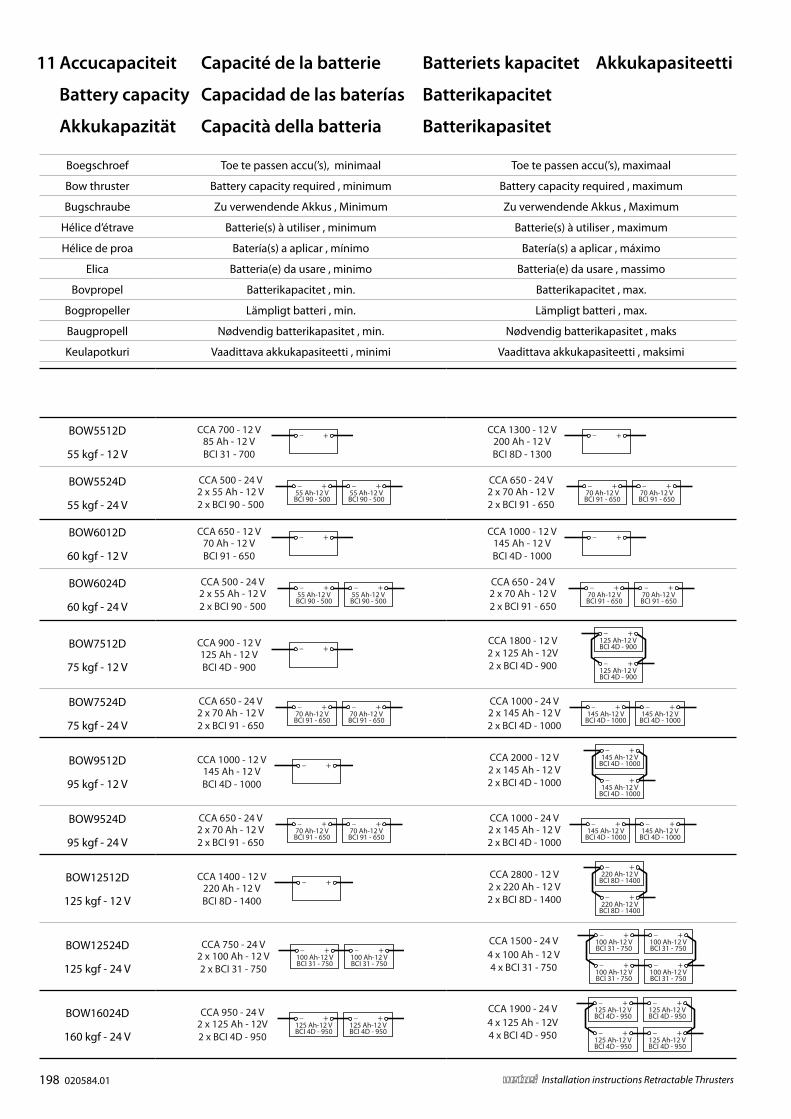
11 Accucapaciteit
Battery capacity
Akkukapazität
Boegschroef Toe te passen accu(’s), minimaal Toe te passen accu(’s), maximaal
Bow thruster Battery capacity required , minimum Battery capacity required , maximum
Bugschraube Zu verwendende Akkus , Minimum Zu verwendende Akkus , Maximum
Hélice d’étrave Batterie(s) à utiliser , minimum Batterie(s) à utiliser , maximum
Hélice de proa Batería(s) a aplicar , mínimo Batería(s) a aplicar , máximo
Elica Batteria(e) da usare , minimo Batteria(e) da usare , massimo
Bovpropel Batterikapacitet , min. Batterikapacitet , max.
Bogpropeller Lämpligt batteri , min. Lämpligt batteri , max.
Baugpropell Nødvendig batterikapasitet , min. Nødvendig batterikapasitet , maks
Keulapotkuri Vaadittava akkukapasiteetti , minimi Vaadittava akkukapasiteetti , maksimi
BOW3512D
35 kgf - 12 V
55 Ah - 12 VBCI 90 - 500
CCA 500 - 12 V100 Ah - 12 VBCI 31 - 750
CCA 750 - 12 VBOW5512D
55 kgf - 12 V85 Ah - 12 VBCI 31 - 700
CCA 700 - 12 V200 Ah - 12 VBCI 8D - 1300
CCA 1300 - 12 V
BOW5524D
55 kgf - 24 V2 x 55 Ah - 12 V2 x BCI 90 - 500
55 Ah-12 VBCI 90 - 500
55 Ah-12 VBCI 90 - 500
CCA 500 - 24 V2 x 70 Ah - 12 V2 x BCI 91 - 650
70 Ah-12 VBCI 91 - 650
70 Ah-12 VBCI 91 - 650
CCA 650 - 24 V
BOW6012D
60 kgf - 12 V70 Ah - 12 VBCI 91 - 650
CCA 650 - 12 V145 Ah - 12 VBCI 4D - 1000
CCA 1000 - 12 V
BOW6024D
60 kgf - 24 V2 x 55 Ah - 12 V2 x BCI 90 - 500
55 Ah-12 VBCI 90 - 500
55 Ah-12 VBCI 90 - 500
CCA 500 - 24 V2 x 70 Ah - 12 V2 x BCI 91 - 650
70 Ah-12 VBCI 91 - 650
70 Ah-12 VBCI 91 - 650
CCA 650 - 24 V
BOW7512D
75 kgf - 12 V125 Ah - 12 VBCI 4D - 900
CCA 900 - 12 V2 x 125 Ah - 12V2 x BCI 4D - 900
125 Ah-12 VBCI 4D - 900
125 Ah-12 VBCI 4D - 900
CCA 1800 - 12 V
BOW7524D
75 kgf - 24 V2 x 70 Ah - 12 V2 x BCI 91 - 650
70 Ah-12 VBCI 91 - 650
70 Ah-12 VBCI 91 - 650
CCA 650 - 24 V2 x 145 Ah - 12 V2 x BCI 4D - 1000
145 Ah-12 VBCI 4D - 1000
145 Ah-12 VBCI 4D - 1000
CCA 1000 - 24 V
BOW9512D
95 kgf - 12 V145 Ah - 12 VBCI 4D - 1000
CCA 1000 - 12 V2 x 145 Ah - 12 V2 x BCI 4D - 1000
145 Ah-12 VBCI 4D - 1000
145 Ah-12 VBCI 4D - 1000
CCA 2000 - 12 V
BOW9524D
95 kgf - 24 V2 x 70 Ah - 12 V2 x BCI 91 - 650
70 Ah-12 VBCI 91 - 650
70 Ah-12 VBCI 91 - 650
CCA 650 - 24 V2 x 145 Ah - 12 V2 x BCI 4D - 1000
145 Ah-12 VBCI 4D - 1000
145 Ah-12 VBCI 4D - 1000
CCA 1000 - 24 V
BOW12512D
125 kgf - 12 V220 Ah - 12 VBCI 8D - 1400
CCA 1400 - 12 V2 x 220 Ah - 12 V2 x BCI 8D - 1400
220 Ah-12 VBCI 8D - 1400
220 Ah-12 VBCI 8D - 1400
CCA 2800 - 12 V
BOW12524D
125 kgf - 24 V2 x 100 Ah - 12 V2 x BCI 31 - 750
100 Ah-12 VBCI 31 - 750
100 Ah-12 VBCI 31 - 750
CCA 750 - 24 V4 x 100 Ah - 12 V4 x BCI 31 - 750
100 Ah-12 VBCI 31 - 750
100 Ah-12 VBCI 31 - 750
CCA 1500 - 24 V 100 Ah-12 VBCI 31 - 750
100 Ah-12 VBCI 31 - 750
BOW16024D
160 kgf - 24 V2 x 125 Ah - 12V2 x BCI 4D - 950
125 Ah-12 VBCI 4D - 950
125 Ah-12 VBCI 4D - 950
CCA 950 - 24 V4 x 125 Ah - 12V4 x BCI 4D - 950
125 Ah-12 VBCI 4D - 950
125 Ah-12 VBCI 4D - 950
CCA 1900 - 24 V 125 Ah-12 VBCI 4D - 950
125 Ah-12 VBCI 4D - 950
Capacité de la batterie
Capacidad de las baterías
Capacità della batteria
Batteriets kapacitet
Batterikapacitet
Batterikapasitet
Akkukapasiteetti
020584.01 199vetus® Installation instructions Retractable Thrusters
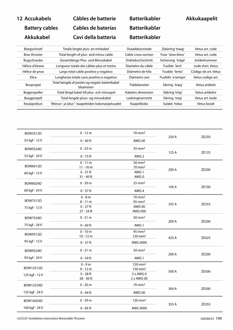
12 Accukabels
Battery cables
Akkukabel
Câbles de batterie
Cables de baterías
Cavi della batteria
Batterikabler
Batterikablar
Batterikabler
Akkukaapelit
Boegschroef Totale lengte plus- en minkabel Draaddoorsnede Zekering ‘traag’ Vetus art. code
Bow thruster Total length of plus- and minus cable Cable cross-section Fuse ‘slow blow’ Vetus art. code
Bugschraube Gesamtlänge Plus- und Minuskabel Drahtdurchschnitt Sicherung ‘träge’ Artikelnummer
Hélice d'étrave Longueur totale des câbles plus et moins Diamètre du câble Fusible ‘lent’ code d'art. Vetus
Hélice de proa Largo total cable positivo y negativo Diámetro de hilo Fusible ‘lento’ Código de art. Vetus
Elica Lunghezza totale cavo positivo e negativo Diametro cavi Fusibile ‘a tempo’ Vetus codigo art.
BovpropelTotal længde af positiv og negativ batterikabel
tilsammenTråd diameter Sikring ‘træg’ Vetus artikeln
Bogpropeller Total längd kabel till plus- och minuspol Kabelns dimension Säkring ‘trög’ Vetus artikelnr
Baugpropell Total lengde pluss- og minuskabel Ledningtverrsnitt Sikring ‘treg’ Vetus art. kode
Keulapotkuri ‘Miinus’- ja ‘plus”- kaapeleiden kokonaispituudet Kaapelikoko Sulake hidas Vetus koodi
BOW3512D
35 kgf - 12 V
0 - 11 m 35 mm2
160 A ZE1600 - 34 ft
34 - 43 ft
AWG 2
AWG 1
BOW5512D
55 kgf - 12 V
0 - 12 m 70 mm2
250 A ZE2500 - 40 ft AWG 00
BOW5524D
55 kgf - 24 V
0 - 23 m 35 mm2
125 A ZE1250 - 73 ft AWG 2
BOW6012D
60 kgf - 12 V
0 - 11 m11 - 16 m
50 mm2
70 mm2200 A ZE200
0 - 31 ft31 - 40 ft
AWG 1AWG 0
BOW6024D
60 kgf - 24 V
0 - 20 m 25 mm2
100 A ZE1000 - 57 ft AWG 4
BOW7512D
75 kgf - 12 V
0 - 8 m8 - 11 m
70 mm2
95 mm2355 A ZE355
0 - 27 ft27 - 34 ft
AWG 00AWG 000
BOW7524D
75 kgf - 24 V
0 - 21 m 50 mm2
200 A ZE2000 - 60 ft AWG 1
BOW9512D
95 kgf - 12 V
0 - 10 m10 - 12 m
95 mm2
120 mm2425 A ZE425
0 - 37 ft AWG 0000
BOW9524D
95 kgf - 24 V
0 - 21 m 50 mm2
200 A ZE2000 - 59 ft AWG 1
BOW12512D
125 kgf - 12 V
0 - 9 m9 - 12 m
120 mm2
150 mm2500 A ZE500
0 - 28 ft28 - 36 ft
2 x AWG 02 x AWG 00
BOW12524D
125 kgf - 24 V
0 - 20 m 70 mm2
300 A ZE3000 - 64 ft AWG 00
BOW16024D
160 kgf - 24 V
0 - 29 m 120 mm2
355 A ZE3550 - 85 ft AWG 0000

vetus b.v.FOKKERSTRAAT 571 - 3125 BD SCHIEDAM - HOLLANDTEL.: +31 0(0)88 4884700 - [email protected] - www.vetus.com
Printed in the Netherlands020584.01 2017-03