Embed Size (px)
Citation preview

THS710A, THS720A,THS730A & THS720PTekScopeUser Manual
070-9731-05
This document applies to serial number B010100and above and firmware version 1.13 and above.
First printing: February 1998

Copyright � Tektronix, Inc. All rights reserved.
Tektronix products are covered by U.S. and foreign patents, issued andpending. Information in this publication supercedes that in all previouslypublished material. Specifications and price change privileges reserved.
Printed in the U.S.A.
Tektronix, Inc., P.O. Box 1000, Wilsonville, OR 97070–1000
TEKTRONIX and TEK are registered trademarks of Tektronix, Inc.
Tek Secure is a registered trademark of Tektronix, Inc.
TekTools, TekScope, and IsolatedChannel are trademarks of Tektronix, Inc.

WARRANTY
Tektronix warrants that the products that it manufactures and sells will be free from defectsin materials and workmanship for a period of three (3) years from the date of purchasefrom an authorized Tektronix distributor. If any such product proves defective during thiswarranty period, Tektronix, at its option, either will repair the defective product withoutcharge for parts and labor, or will provide a replacement in exchange for the defectiveproduct. Batteries are excluded from this warranty.
In order to obtain service under this warranty, Customer must notify Tektronix of thedefect before the expiration of the warranty period and make suitable arrangements for theperformance of service. Customer shall be responsible for packaging and shipping thedefective product to the service center designated by Tektronix, shipping charges prepaid,and with a copy of customer proof of purchase. Tektronix shall pay for the return of theproduct to Customer if the shipment is to a location within the country in which theTektronix service center is located. Customer shall be responsible for paying all shippingcharges, duties, taxes, and any other charges for products returned to any other locations.
This warranty shall not apply to any defect, failure or damage caused by improper use orimproper or inadequate maintenance and care. Tektronix shall not be obligated to furnishservice under this warranty a) to repair damage resulting from attempts by personnel otherthan Tektronix representatives to install, repair or service the product; b) to repair damageresulting from improper use or connection to incompatible equipment; c) to repair anydamage or malfunction caused by the use of non–Tektronix supplies; or d) to service aproduct that has been modified or integrated with other products when the effect of suchmodification or integration increases the time or difficulty of servicing the product.
THIS WARRANTY IS GIVEN BY TEKTRONIX WITH RESPECT TO THELISTED PRODUCTS IN LIEU OF ANY OTHER WARRANTIES, EXPRESS ORIMPLIED. TEKTRONIX AND ITS VENDORS DISCLAIM ANY IMPLIEDWARRANTIES OF MERCHANTABILITY OR FITNESS FOR A PARTICULARPURPOSE. TEKTRONIX’ RESPONSIBILITY TO REPAIR OR REPLACEDEFECTIVE PRODUCTS IS THE SOLE AND EXCLUSIVE REMEDYPROVIDED TO THE CUSTOMER FOR BREACH OF THIS WARRANTY.TEKTRONIX AND ITS VENDORS WILL NOT BE LIABLE FOR ANYINDIRECT, SPECIAL, INCIDENTAL, OR CONSEQUENTIAL DAMAGESIRRESPECTIVE OF WHETHER TEKTRONIX OR THE VENDOR HASADVANCE NOTICE OF THE POSSIBILITY OF SUCH DAMAGES.
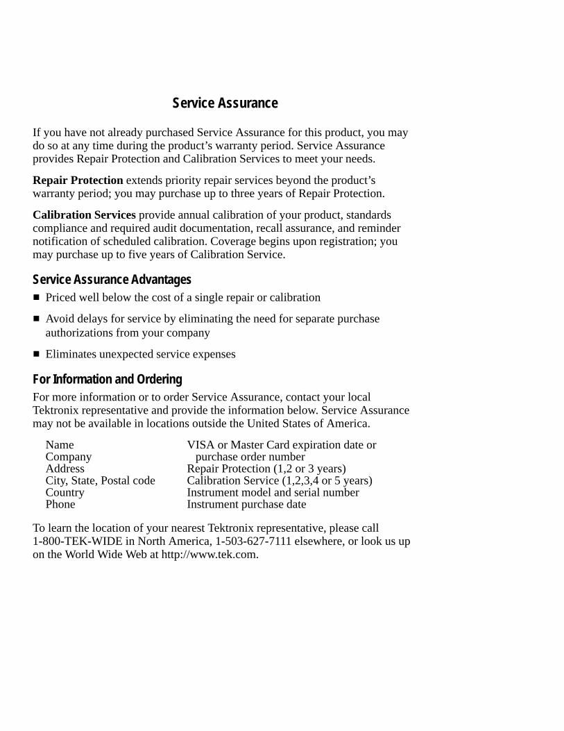
Service Assurance
If you have not already purchased Service Assurance for this product, you maydo so at any time during the product’s warranty period. Service Assuranceprovides Repair Protection and Calibration Services to meet your needs.
Repair Protection extends priority repair services beyond the product’swarranty period; you may purchase up to three years of Repair Protection.
Calibration Services provide annual calibration of your product, standardscompliance and required audit documentation, recall assurance, and remindernotification of scheduled calibration. Coverage begins upon registration; youmay purchase up to five years of Calibration Service.
Service Assurance Advantages� Priced well below the cost of a single repair or calibration
� Avoid delays for service by eliminating the need for separate purchaseauthorizations from your company
� Eliminates unexpected service expenses
For Information and OrderingFor more information or to order Service Assurance, contact your localTektronix representative and provide the information below. Service Assurancemay not be available in locations outside the United States of America.
Name VISA or Master Card expiration date orCompany purchase order numberAddress Repair Protection (1,2 or 3 years)City, State, Postal code Calibration Service (1,2,3,4 or 5 years)Country Instrument model and serial numberPhone Instrument purchase date
To learn the location of your nearest Tektronix representative, please call1-800-TEK-WIDE in North America, 1-503-627-7111 elsewhere, or look us upon the World Wide Web at http://www.tek.com.
THS710A, THS720A, THS730A & THS720P User Manual i
Table of Contents
General Safety Summary iii. . . . . . . . . . . . . . . . . . . . . . . . . . . .
Preface v. . . . . . . . . . . . . . . . . . . . . . . . . . . . . . . . . . . . . . . . . . . . In This Manual v. . . . . . . . . . . . . . . . . . . . . . . . . . . . . . . . . . . . . . Conventions vi. . . . . . . . . . . . . . . . . . . . . . . . . . . . . . . . . . . . . . . .
Getting StartedProduct Description 1–1. . . . . . . . . . . . . . . . . . . . . . . . . . . . . . . . . . Replacing the Battery Pack 1–5. . . . . . . . . . . . . . . . . . . . . . . . . . . . Using External Power 1–7. . . . . . . . . . . . . . . . . . . . . . . . . . . . . . . . Using the Tilt Stand 1–8. . . . . . . . . . . . . . . . . . . . . . . . . . . . . . . . . . Functional Check 1–9. . . . . . . . . . . . . . . . . . . . . . . . . . . . . . . . . . . .
Operating BasicsFunctional Overview 2–1. . . . . . . . . . . . . . . . . . . . . . . . . . . . . . . . Understanding the Front Panel 2–1. . . . . . . . . . . . . . . . . . . . . . . . . Using Scope Mode 2–8. . . . . . . . . . . . . . . . . . . . . . . . . . . . . . . . . . . Using Meter Mode 2–9. . . . . . . . . . . . . . . . . . . . . . . . . . . . . . . . . . . Compensating the Oscilloscope Probes 2–10. . . . . . . . . . . . . . . . . . . Compensating the Oscilloscope Signal Path 2–11. . . . . . . . . . . . . . . Taking Floating Measurements 2–12. . . . . . . . . . . . . . . . . . . . . . . . .
General-Purpose Application Examples 2–15. . . . . . . . . . . . . . . . Displaying an Unknown Signal 2–16. . . . . . . . . . . . . . . . . . . . . . . . . Measuring Resistance 2–18. . . . . . . . . . . . . . . . . . . . . . . . . . . . . . . . Measuring the Frequency of a Clock Signal 2–20. . . . . . . . . . . . . . . Measuring Propagation Delay 2–22. . . . . . . . . . . . . . . . . . . . . . . . . . Triggering on a Missing Data Pulse 2–24. . . . . . . . . . . . . . . . . . . . . Detecting Narrow Glitches 2–26. . . . . . . . . . . . . . . . . . . . . . . . . . . . Triggering on a Third Signal 2–28. . . . . . . . . . . . . . . . . . . . . . . . . . . Analyzing a Serial Data Communication Link 2–30. . . . . . . . . . . . . Triggering on a Video Signal 2–32. . . . . . . . . . . . . . . . . . . . . . . . . . .
Power-Measurement Application Examples 2–35. . . . . . . . . . . . . Testing a Switching Transistor Drive Circuit 2–36. . . . . . . . . . . . . . Measuring Instantaneous Power Dissipation
in a Switching Transistor 2–38. . . . . . . . . . . . . . . . . . . . . . . . . . .

Table of Contents
ii THS710A, THS720A, THS730A & THS720P User Manual
Monitoring for Power Surges and Dropouts 2–40. . . . . . . . . . . . . . . Detecting a Missing Power Cycle 2–42. . . . . . . . . . . . . . . . . . . . . . . Measuring Harmonic Current (THS720P) 2–44. . . . . . . . . . . . . . . . . Taking Power Measurements (THS720P) 2–46. . . . . . . . . . . . . . . . . Measuring Motor Start-Up Current 2–48. . . . . . . . . . . . . . . . . . . . . . Triggering at a Specific Motor RPM 2–50. . . . . . . . . . . . . . . . . . . . . Triggering on a Motor Drive Waveform (THS720P) 2–52. . . . . . . .
ReferenceIntroduction to Reference 3–1. . . . . . . . . . . . . . . . . . . . . . . . . . . . ACQUIRE 3–3. . . . . . . . . . . . . . . . . . . . . . . . . . . . . . . . . . . . . . . . . AUTORANGE 3–8. . . . . . . . . . . . . . . . . . . . . . . . . . . . . . . . . . . . . . CURSOR 3–11. . . . . . . . . . . . . . . . . . . . . . . . . . . . . . . . . . . . . . . . . . DISPLAY/HARMONICS 3–13. . . . . . . . . . . . . . . . . . . . . . . . . . . . . HARD COPY 3–22. . . . . . . . . . . . . . . . . . . . . . . . . . . . . . . . . . . . . . HOLD 3–26. . . . . . . . . . . . . . . . . . . . . . . . . . . . . . . . . . . . . . . . . . . . HORIZONTAL Controls 3–27. . . . . . . . . . . . . . . . . . . . . . . . . . . . . . MEAS 3–31. . . . . . . . . . . . . . . . . . . . . . . . . . . . . . . . . . . . . . . . . . . . METER Mode 3–39. . . . . . . . . . . . . . . . . . . . . . . . . . . . . . . . . . . . . . SAVE/RECALL 3–45. . . . . . . . . . . . . . . . . . . . . . . . . . . . . . . . . . . . . SCOPE Mode 3–48. . . . . . . . . . . . . . . . . . . . . . . . . . . . . . . . . . . . . . . TRIGGER Controls 3–54. . . . . . . . . . . . . . . . . . . . . . . . . . . . . . . . . . UTILITY 3–62. . . . . . . . . . . . . . . . . . . . . . . . . . . . . . . . . . . . . . . . . . VERTICAL Controls 3–68. . . . . . . . . . . . . . . . . . . . . . . . . . . . . . . . .
AppendicesAppendix A: Specifications A–1. . . . . . . . . . . . . . . . . . . . . . . . . . .
Appendix B: Factory Setup B–1. . . . . . . . . . . . . . . . . . . . . . . . . .
Appendix C: Accessories C–1. . . . . . . . . . . . . . . . . . . . . . . . . . . . .
Appendix D: Performance Verification D–1. . . . . . . . . . . . . . . . . Test Record D–2. . . . . . . . . . . . . . . . . . . . . . . . . . . . . . . . . . . . . . . . Performance Verification Procedures D–4. . . . . . . . . . . . . . . . . . . .
Appendix E: General Care and Cleaning E–1. . . . . . . . . . . . . . . General Care E–1. . . . . . . . . . . . . . . . . . . . . . . . . . . . . . . . . . . . . . . Cleaning E–1. . . . . . . . . . . . . . . . . . . . . . . . . . . . . . . . . . . . . . . . . . .
Glossary and Index

THS710A, THS720A, THS730A & THS720P User Manual iii
General Safety Summary
Review the following safety precautions to avoid injury and preventdamage to this product or any products connected to it. To avoidpotential hazards, use this product only as specified.
Only qualified personnel should perform service procedures.
To Avoid Fire or Personal InjuryConnect and Disconnect Properly. Do not connect or disconnect probesor test leads while they are connected to a voltage source.
Observe All Terminal Ratings. To avoid fire or shock hazard, observe allratings and markings on the product. Consult the product manual forfurther ratings information before making connections to the product.
Do not apply a potential to any terminal, including the commonterminal, that exceeds the maximum rating of that terminal.
Replace Batteries Properly. Replace batteries only with the proper typeand rating specified.
Recharge Batteries Properly. Recharge batteries for the recommendedcharge cycle only.
Use Proper AC Adapter. Use only the AC adapter specified for thisproduct.
Do Not Operate Without Covers. Do not operate this product withcovers or panels removed.
Avoid Exposed Circuitry. Do not touch exposed connections andcomponents when power is present.
Do Not Operate With Suspected Failures. If you suspect there is damageto this product, have it inspected by qualified service personnel.
Do Not Operate in an Explosive Atmosphere.
Do Not Operate in Wet/Damp Conditions.

General Safety Summary
iv THS710A, THS720A, THS730A & THS720P User Manual
Safety Terms and SymbolsTerms in This Manual. These terms may appear in this manual:
WARNING. Warning statements identify conditions or practices thatcould result in injury or loss of life.
CAUTION. Caution statements identify conditions or practices thatcould result in damage to this product or other property.
Terms on the Product. These terms may appear on the product:
DANGER indicates an injury hazard immediately accessible as youread the marking.
WARNING indicates an injury hazard not immediately accessible asyou read the marking.
CAUTION indicates a hazard to property including the product.
Symbols on the Product. These symbols may appear on the product:
CAUTIONRefer to Manual
WARNINGHigh Voltage
DoubleInsulated
Protective Ground(Earth) Terminal
Battery RecyclingThis product contains a Nickel Cadmium (NiCd) battery, which mustbe recycled or disposed of properly. For the location of a localbattery recycler in the U.S. or Canada, please contact:
RBRC (800) BATTERYRechargeable Battery Recycling Corp. (800) 227-7379P.O. Box 141870 www.rbrc.comGainesville, Florida 32614
THS710A, THS720A, THS730A & THS720P User Manual v
Preface
This User Manual describes the capabilities, operation, andapplications of the THS710A, THS720A, THS730A, and THS720PTekScope instruments.
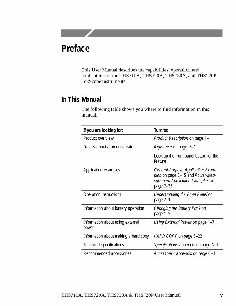
In This ManualThe following table shows you where to find information in thismanual.
If you are looking for: Turn to:
Product overview Product Description on page 1–1
Details about a product feature Reference on page 3–1
Look up the front-panel button for thefeature
Application examples General-Purpose Application Exam-ples on page 2–15 and Power-Mea-surement Application Examples onpage 2–35
Operation instructions Understanding the Front Panel onpage 2–1
Information about battery operation Changing the Battery Pack onpage 1–5
Information about using externalpower
Using External Power on page 1–7
Information about making a hard copy HARD COPY on page 3–22
Technical specifications Specifications appendix on page A–1
Recommended accessories Accessories appendix on page C–1

Preface
vi THS710A, THS720A, THS730A & THS720P User Manual
ConventionsTekScope instrument setups are shown in tables. The OperaingBasics and Performance Verification sections use tables to showspecific setups. The Reference section uses similar tables to show thecomplete contents of the menu system.
The header of each table contains icons that represent the controlsand menu items used to set up the instrument. To make a specificsetup, read the table from left to right and then from top to bottom asshown below. The table contains the symbol “—” if no action isrequired.
1. Choosescope modeor metermode.
2. Press thisbutton on thefront panel.
3. Press thisbezel button.
4. Press thebezel buttonagain untilthis selectionis highlighted.
5. Use the+/– rocker toset the valuefor a parame-ter.
6. 7. —
8. 9. 10.

Getting Started

THS710A, THS720A, THS730A & THS720P User Manual 1–1
Getting Started
In addition to a brief product description, this chapter covers thefollowing topics:
� How to change the battery pack
� How to use external power
� How to use the tilt stand
� How to perform a quick functional check
Product DescriptionThe THS710A, THS720A, THS730A, and THS720P TekScopeinstruments combine a two-channel oscilloscope and a digitalmultimeter (DMM) in a rugged, handheld package.
General Features
� Battery power or external power
� High-resolution, high-contrast display with temperaturecompensation for clear visibility over a wide temperature range
� Onboard waveform, data, and setup storage
� RS-232 communication port to load setups, download wave-forms, and make hard copies
� Fully programmable through the RS-232 communication port

Getting Started
1–2 THS710A, THS720A, THS730A & THS720P User Manual
Oscilloscope FeaturesThe TekScope instrument is a powerful, two-channel oscilloscopewith the following features:
� Autoranging for quick setup and hands-free operation
� 200 MHz (THS730A), 100 MHz (THS720A and THS720P) or60 MHz (THS710A) bandwidth with selectable 20 MHzbandwidth limit
� 1 GS/s (THS730A), 500 MS/s (THS720A and THS720P), or250 MS/s (THS710A) sample rate and 2,500 point record length
� Separate digitizers for each channel (both channels alwaysacquire simultaneously)
� Waveform averaging and enveloping with hardware peakdetection
� Digital Real Time digitizing (up to five-times oversampling),sin(x)/x interpolation, and peak-detect acquisition to limit thepossibility of aliasing
� Independently isolated channels to allow improved safety formeasurements to 1000 VRMS while floating up to 600 VRMSusing P5102 probes
� Cursors and 21 continuously updated, automatic measurements
� Simultaneous oscilloscope and meter operation on the same oron separate signals
� Advanced pulse, video, external, and motor trigger (THS720P)capabilities
� Harmonic analysis and power measurements (THS720P)
Getting Started
THS710A, THS720A, THS730A & THS720P User Manual 1–3
Meter FeaturesThe TekScope instrument is also a full-featured DMM with thefollowing features:
� True RMS VAC, VDC, �, continuity, and diode-check functions
� Autoranging or manual ranging
� Data logger plot of meter measurements over a period of time
� Max, min, delta max-min, relative-delta, and average statistics inthe readout
� Bar graph for an “analog meter” feel
� Independently isolated meter inputs allow floating measurementsto 600 VRMS
� Overvoltage indicator warns when an overvoltage is applied tothe input

Getting Started
1–4 THS710A, THS720A, THS730A & THS720P User Manual
Input and Output Connectors
All input and output connectors are located on the top and sidepanels as shown below. See the back of the instrument for maximumvoltage ratings.
WARNING. To avoid shock hazard, the DC input and I/O port holeplugs must remain closed in wet or damp conditions.
Top panel
Side panel

Getting Started
THS710A, THS720A, THS730A & THS720P User Manual 1–5
Replacing the Battery PackFor portable operation, use the rechargeable battery pack.
You can replace the battery pack without losing any savedinformation. The current setup, saved setups, saved waveforms, andsaved data are all stored in nonvolatile memory that does not dependon battery power. To prevent loss of saved information, set theON/STBY switch to STBY before removing the battery back.
WARNING. To avoid shock hazard, the battery door must remainclosed in wet or damp conditions.
Battery pack
Getting Started
1–6 THS710A, THS720A, THS730A & THS720P User Manual
Battery Life
From a full charge, you can operate the TekScope instrumentcontinuously for approximately two hours. You can extend thebattery life by using automatic Power Off Time-out or BacklightTime-out. Refer to page 3–65 for a description of these features.
The TekScope instrument turns off automatically when the batteryruns low. A low-battery message appears in the display about tenminutes before the automatic shutdown.
Nickel-cadmium batteries can lose capacity permanently if notallowed to discharge completely. Whenever possible, allow thebattery to discharge completely before you recharge it to minimizethis capacity loss.
Charging the Battery Pack
You can use external power to charge the battery pack while it is inthe TekScope instrument. Or you can charge the battery pack withthe optional external battery charger.
NOTE. Before using the battery for the first time, it must be charged.
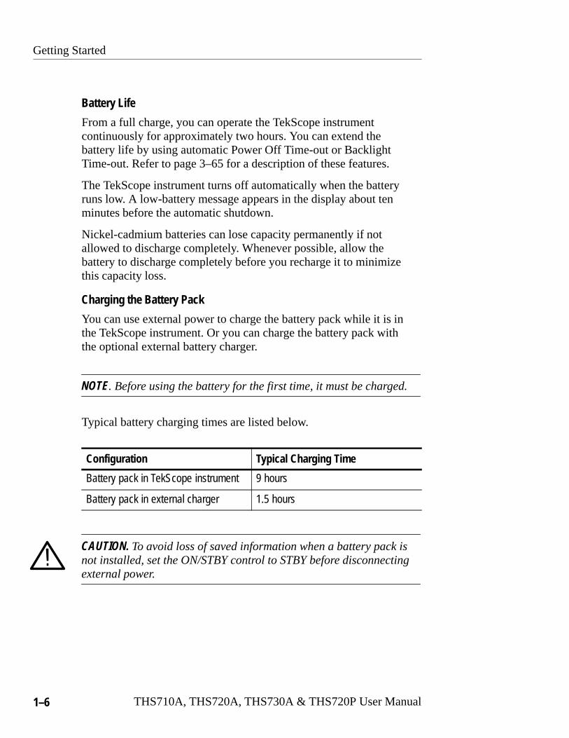
Typical battery charging times are listed below.
Configuration Typical Charging Time
Battery pack in TekScope instrument 9 hours
Battery pack in external charger 1.5 hours
CAUTION. To avoid loss of saved information when a battery pack isnot installed, set the ON/STBY control to STBY before disconnectingexternal power.

Getting Started
THS710A, THS720A, THS730A & THS720P User Manual 1–7
Using External PowerUsing external power from the AC adapter or cigarette lighteradapter has the following advantages:
� Saves internal battery power for portable operation later
� Charges internal battery pack
� Allows extended operation; the Standby Time-out and BacklightTime-out features are automatically disabled when externalpower is used
� Maintains floating measurement capability of the oscilloscopechannels and DMM
Attach the external power source as shown below.
The DC INPUT disconnects itself if an overvoltage is applied. If thisoccurs, disconnect and then reconnect the AC adapter or cigarettelighter adapter to resume operation from external power.
External power toDC INPUT
CAUTION. To avoid overheating, do not connect external power whilethe instrument is in a confined space, such as in the soft case.

Getting Started
1–8 THS710A, THS720A, THS730A & THS720P User Manual
Using the Tilt StandA built-in tilt stand folds out and snaps back into place when not inuse. For benchtop use, lock the tilt stand in place with the hingedflap. To hang the TekScope instrument over a nail, rotate the tiltstand 180°. You can also extend the hinged flap as shown to hang theinstrument from a ladder rung or over the top of a door.
Getting Started
THS710A, THS720A, THS730A & THS720P User Manual 1–9
Functional CheckAfter you install batteries or connect external power, you canperform this quick functional check to verify that your TekScopeinstrument is operating correctly.
1. Press the ON/STBY button to turn on the TekScope instrument.
2. After a few seconds, you should see a window with the messagePower-On self check PASSED. Press the CLEAR MENU button.
3. Press the SCOPE button.
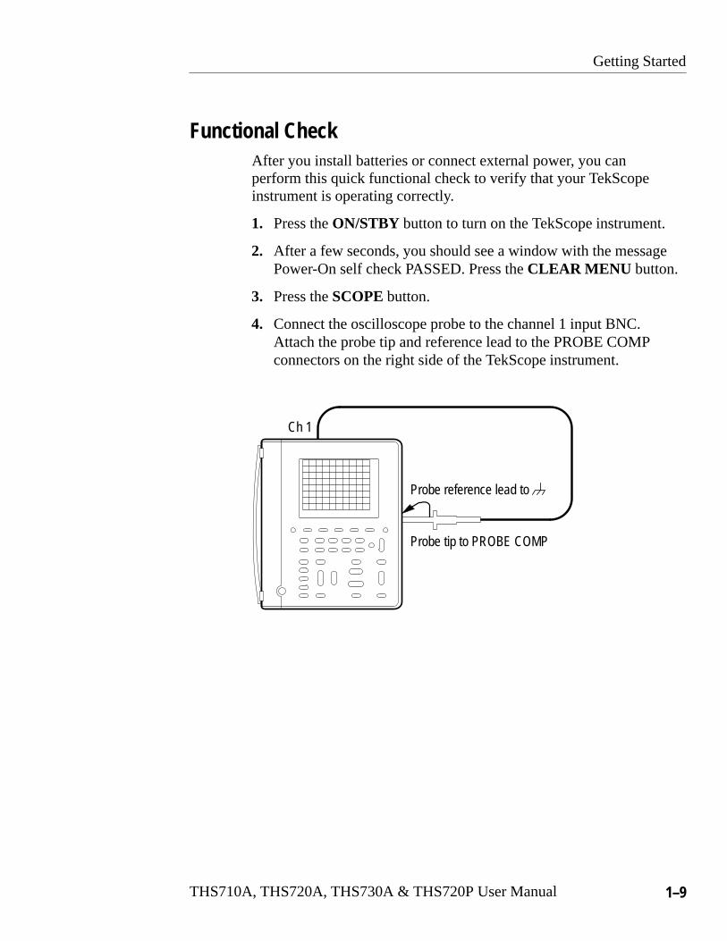
4. Connect the oscilloscope probe to the channel 1 input BNC.Attach the probe tip and reference lead to the PROBE COMPconnectors on the right side of the TekScope instrument.
Probe tip to PROBE COMP
Probe reference lead to
Ch 1
Getting Started
1–10 THS710A, THS720A, THS730A & THS720P User Manual
5. Press the AUTORANGE button. Within a few seconds, youshould see a square wave in the display (approximately 1.2 kHz).
If you want, repeat steps 4 and 5 for channel 2 of the oscillo-scope.
6. Press the METER button.
7. Press the VDC bezel button
8. Press the AUTORANGE button.
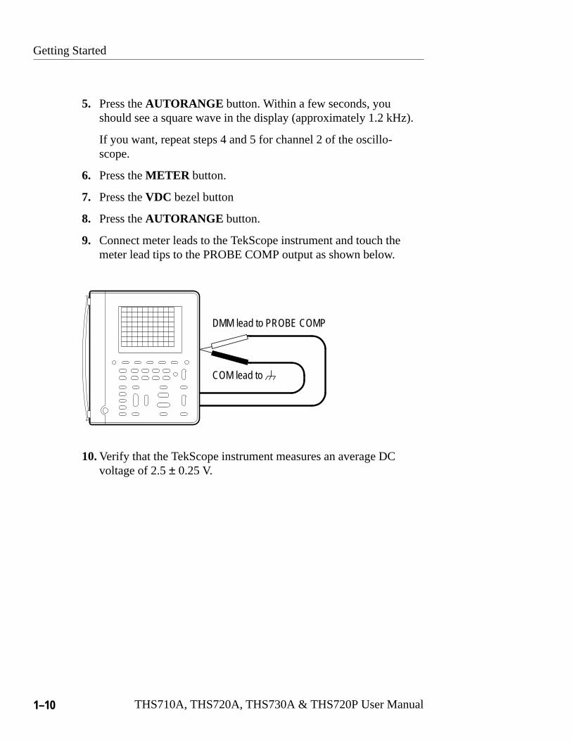
9. Connect meter leads to the TekScope instrument and touch themeter lead tips to the PROBE COMP output as shown below.
DMM lead to PROBE COMP
COM lead to
10.Verify that the TekScope instrument measures an average DCvoltage of 2.5 ± 0.25 V.

Operating Basics


THS710A, THS720A, THS730A & THS720P User Manual 2–1
Functional Overview
This section covers the following topics:
� Understanding the front panel
� Using scope mode
� Using meter mode
� Connecting and using the probes
� Taking floating measurements
You can find specific information about each of the controls in theReference chapter of this manual.
Understanding the Front PanelThe front panel has buttons for the functions you use most often andmenus to access more specialized functions. With the autorangefeature, you can setup the TekScope instrument automatically in bothscope and meter modes.
Using the Menu System
To use the menu system, follow the steps shown on the nexttwo pages.

Functional Overview
2–2 THS710A, THS720A, THS730A & THS720P User Manual
1. Press a front-panel button to display the menu you want to use.
2. Press a bezel button to choose a menu item. If a pop-up menuappears, continue to press the bezel button to choose an item inthe pop-up menu. You may need to press the Select Page bezelbutton to access additional menu items.
Functional Overview
THS710A, THS720A, THS730A & THS720P User Manual 2–3
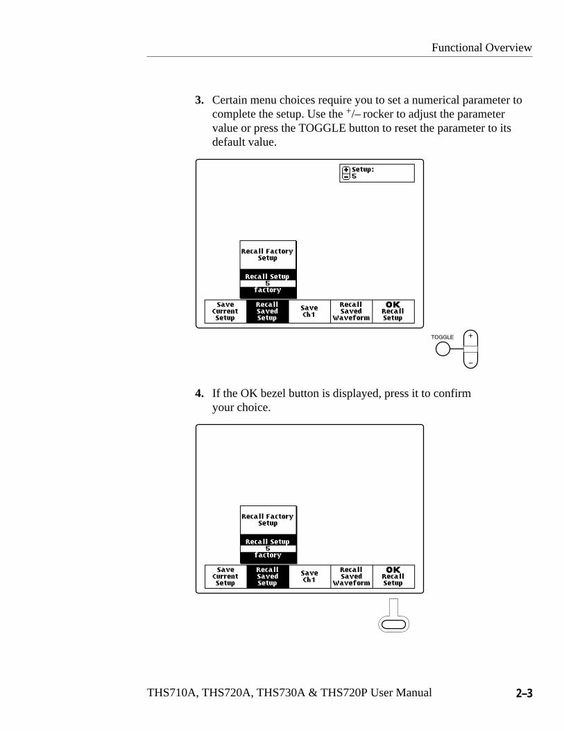
3. Certain menu choices require you to set a numerical parameter tocomplete the setup. Use the +/– rocker to adjust the parametervalue or press the TOGGLE button to reset the parameter to itsdefault value.
4. If the OK bezel button is displayed, press it to confirmyour choice.

Functional Overview
2–4 THS710A, THS720A, THS730A & THS720P User Manual
Using the Menu Buttons
You can use the menu buttons below to perform many functions ofthe TekScope instrument. Many of these buttons operate differentlyin scope or meter mode.
1 2 3 4 5 6
9 8 7
1. ACQUIRE.
Sets acquisition modes.
Sets calculation mode of data logger.
2. SAVE/RECALL. Saves and recalls setups, waveforms, or DMMdata.

Functional Overview
THS710A, THS720A, THS730A & THS720P User Manual 2–5
3. MEASURE. Performs automated measurements of waveforms ordata logger display.
4. DISPLAY.
Changes appearance of waveform and display. Activatesharmonics (THS720P only).
Changes appearance of data logger display.
5. CURSOR. Activates scope or data logger cursors.
6. UTILITY. Activates system utility functions.
7. TRIGGER.
Activates trigger functions.
8. HORIZONTAL.
Changes horizontal characteristics of waveforms.
Adjusts scroll rate of data logger display.
9. VERTICAL.
Adjusts scale and position of waveform. Sets input parame-ters.
Adjusts position of data logger display. Zooms data loggerdisplay. Sets volts scale. Changes meter range. Changes verticalscale.
Functional Overview
2–6 THS710A, THS720A, THS730A & THS720P User Manual
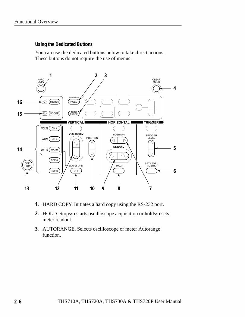
Using the Dedicated Buttons
You can use the dedicated buttons below to take direct actions.These buttons do not require the use of menus.
4
2
5
6
8 7910111213
16
15
14
31
1. HARD COPY. Initiates a hard copy using the RS-232 port.
2. HOLD. Stops/restarts oscilloscope acquisition or holds/resetsmeter readout.
3. AUTORANGE. Selects oscilloscope or meter Autorangefunction.

Functional Overview
THS710A, THS720A, THS730A & THS720P User Manual 2–7
4. CLEAR MENU. Clears menu from display.
5. TRIGGER LEVEL. Adjusts trigger level.
6. SET LEVEL TO 50%. Sets trigger level to midpoint ofoscilloscope waveform.
7. HORIZONTAL POSITION. Adjusts oscilloscope waveformhorizontal position.
8. MAG. Turns 10X horizontal magnification on and off.
9. SEC/DIV. Adjusts horizontal scale factor for oscilloscope or datalogger.
10. VERTICAL POSITION. Adjusts vertical position of oscilloscopewaveform and DMM data logger display.
11. WAVEFORM OFF. Removes selected oscilloscope waveformfrom display.
12. VOLTS/DIV. Adjusts oscilloscope vertical scale factor or meterrange.
13. ON/STBY. Selects on or standby. Does not disconnect powerfrom the instrument.
14. CH 1, CH 2, MATH, REF A, REF B. Displays waveform andchooses selected waveform. In harmonics mode (THS720P),CH 1 and CH 2 also display harmonics of voltage and currentwaveforms; MATH displays power measurements.
15. SCOPE. Selects scope mode.
16. METER. Selects meter mode.

Functional Overview
2–8 THS710A, THS720A, THS730A & THS720P User Manual
Using Scope ModePress the front-panel SCOPE button to enter scope mode. Then,press AUTORANGE to set the vertical, horizontal, and triggerautomatically for a usable display.
The scope-mode display, shown below, is divided into four sections.Refer to SCOPE Mode on page 3–48 for a description of eachsection.
Status line
Waveform readout lines
Measurementreadout area
Graticulearea
Functional Overview
THS710A, THS720A, THS730A & THS720P User Manual 2–9
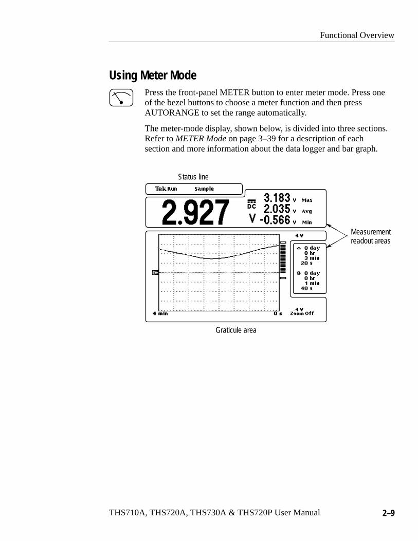
Using Meter ModePress the front-panel METER button to enter meter mode. Press oneof the bezel buttons to choose a meter function and then pressAUTORANGE to set the range automatically.
The meter-mode display, shown below, is divided into three sections.Refer to METER Mode on page 3–39 for a description of eachsection and more information about the data logger and bar graph.
Graticule area
Measurementreadout areas
Status line

Functional Overview
2–10 THS710A, THS720A, THS730A & THS720P User Manual
Compensating the Oscilloscope ProbesTo maintain signal fidelity, you must compensate each voltage probefor the channel input it is connected to.
1. Connect the oscilloscope probe and then press AUTORANGE .
Probe tip to PROBE COMP
Probe reference lead to
Ch 1
AUTORANGE
2. Check the shape of the displayed waveform.
Compensated correctly
Overcompensated
Undercompensated
Functional Overview
THS710A, THS720A, THS730A & THS720P User Manual 2–11
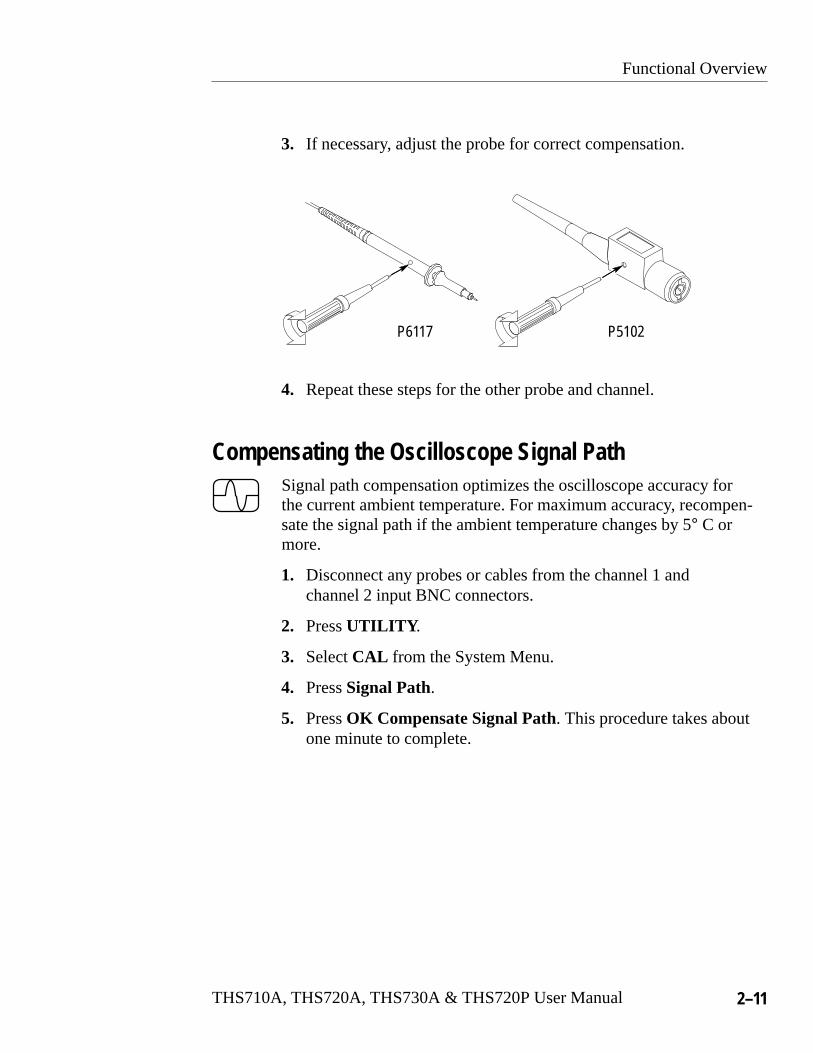
3. If necessary, adjust the probe for correct compensation.
P6117 P5102
4. Repeat these steps for the other probe and channel.
Compensating the Oscilloscope Signal PathSignal path compensation optimizes the oscilloscope accuracy forthe current ambient temperature. For maximum accuracy, recompen-sate the signal path if the ambient temperature changes by 5° C ormore.
1. Disconnect any probes or cables from the channel 1 andchannel 2 input BNC connectors.
2. Press UTILITY .
3. Select CAL from the System Menu.
4. Press Signal Path.
5. Press OK Compensate Signal Path. This procedure takes aboutone minute to complete.

Functional Overview
2–12 THS710A, THS720A, THS730A & THS720P User Manual
Taking Floating MeasurementsThis section covers important issues to consider when taking floatingmeasurements.
Architecture is Important
For taking floating measurements, the TekScope instrument hasan architectural difference from most other oscilloscopes. Thechannel 1, channel 2, and DMM inputs are isolated from the mainchassis and from each other. This architecture allows independentfloating measurements with channel 1, channel 2, and the DMM.
Electrically insulated case
Oscilloscope channels and DMMfloat independently.
DC and/orAC voltage
TekScope instrument architecture
Functional Overview
THS710A, THS720A, THS730A & THS720P User Manual 2–13
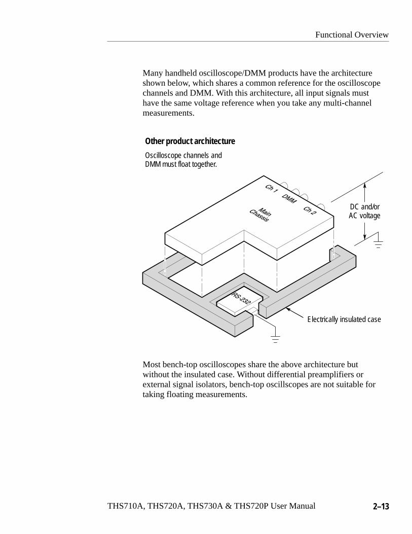
Many handheld oscilloscope/DMM products have the architectureshown below, which shares a common reference for the oscilloscopechannels and DMM. With this architecture, all input signals musthave the same voltage reference when you take any multi-channelmeasurements.
Electrically insulated case
Oscilloscope channels andDMM must float together.
DC and/orAC voltage
Other product architecture
Most bench-top oscilloscopes share the above architecture butwithout the insulated case. Without differential preamplifiers orexternal signal isolators, bench-top oscillscopes are not suitable fortaking floating measurements.

Functional Overview
2–14 THS710A, THS720A, THS730A & THS720P User Manual
Attach the Reference Leads Correctly
If you are using both of the oscilloscope channels, you must attachthe probe reference lead for each channel directly to your circuit.These attachments are required because the oscilloscope channelsare electrically isolated; they do not share a common chassisconnection. Use the shortest possible reference lead with each probeto maintain good signal fidelity. If you are also using the DMM, youmust also attach the DMM common lead to your circuit for the samereason as above.
The probe reference lead presents a higher capacitive load to thecircuit-under-test than the probe tip. When taking a floatingmeasurement between two nodes of a circuit, attach the probereference lead to the lowest impedance or least dynamic of the twonodes.
Beware of High Voltages
Understand the voltage ratings for the probes you are using and donot exceed those ratings. Two ratings are important to know andunderstand:
� The maximum measurement voltage from the probe tip to theprobe reference lead
� The maximum floating voltage from the probe reference lead toearth ground
These two voltage ratings depend on the probe and your application.Refer to Specifications beginning on page A–1 for more information.
WARNING. To prevent electrical shock, do not exceed the measure-ment or floating voltage ratings for the oscilloscope input BNCconnector, probe tip, probe reference lead, DMM input connector, orDMM lead.

THS710A, THS720A, THS730A & THS720P User Manual 2–15
General-Purpose Application Examples
This section presents a series of general-purpose applicationexamples. These simplified examples highlight the features of theTekScope instrument and give you ideas about using it to solve yourown test problems.
The first two examples demonstrate basic scope and meter operation.The remaining examples provide an overview of applications thatcover the following areas:
� Digital circuit testing
� Analog circuit testing
� Video signal testing
General-Purpose Application Examples
2–16 THS710A, THS720A, THS730A & THS720P User Manual
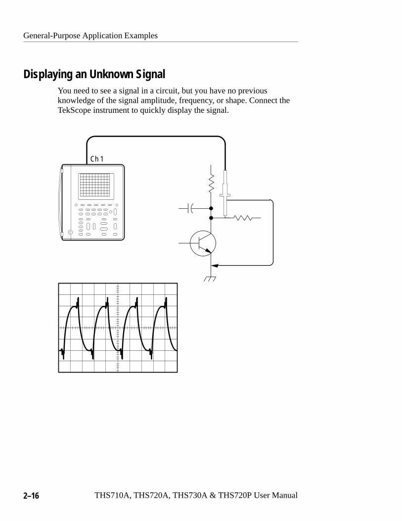
Displaying an Unknown SignalYou need to see a signal in a circuit, but you have no previousknowledge of the signal amplitude, frequency, or shape. Connect theTekScope instrument to quickly display the signal.
Ch 1
General-Purpose Application Examples
THS710A, THS720A, THS730A & THS720P User Manual 2–17
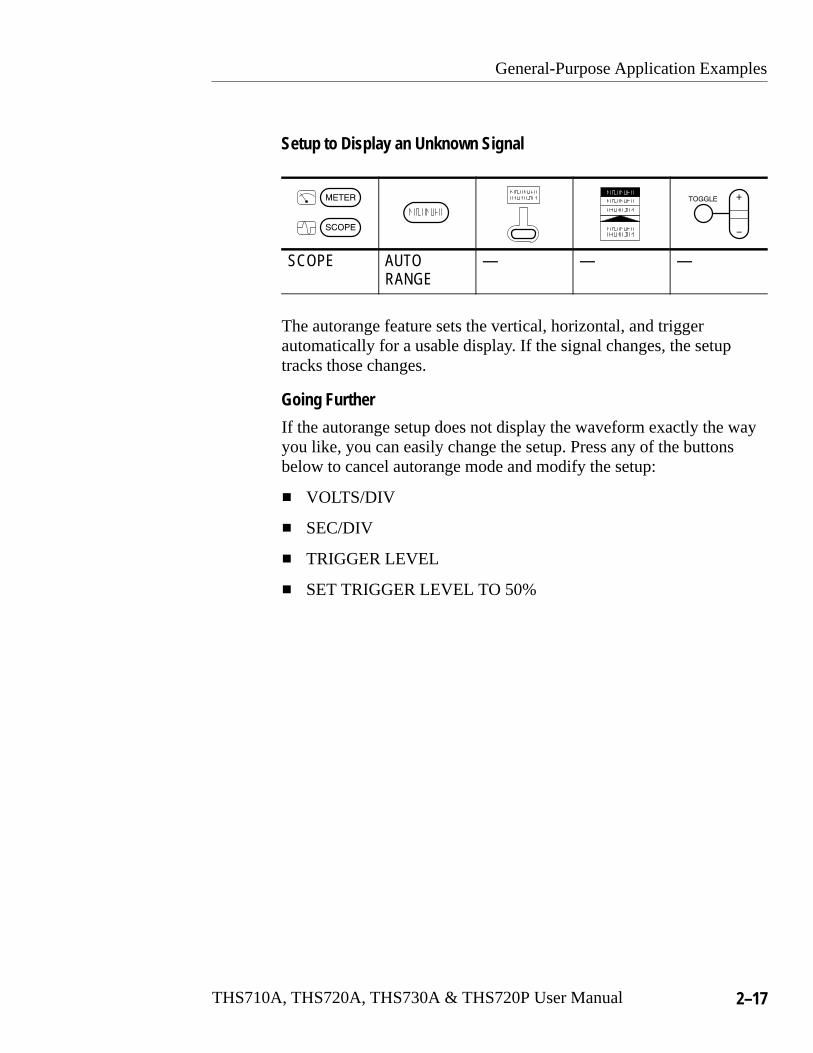
Setup to Display an Unknown Signal
SCOPE AUTORANGE
— — —
The autorange feature sets the vertical, horizontal, and triggerautomatically for a usable display. If the signal changes, the setuptracks those changes.
Going Further
If the autorange setup does not display the waveform exactly the wayyou like, you can easily change the setup. Press any of the buttonsbelow to cancel autorange mode and modify the setup:
� VOLTS/DIV
� SEC/DIV
� TRIGGER LEVEL
� SET TRIGGER LEVEL TO 50%
General-Purpose Application Examples
2–18 THS710A, THS720A, THS730A & THS720P User Manual
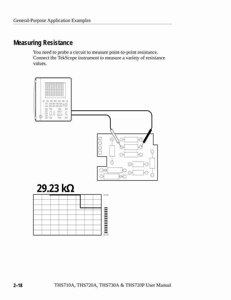
Measuring ResistanceYou need to probe a circuit to measure point-to-point resistance.Connect the TekScope instrument to measure a variety of resistancevalues.
29.23 k�
General-Purpose Application Examples
THS710A, THS720A, THS730A & THS720P User Manual 2–19
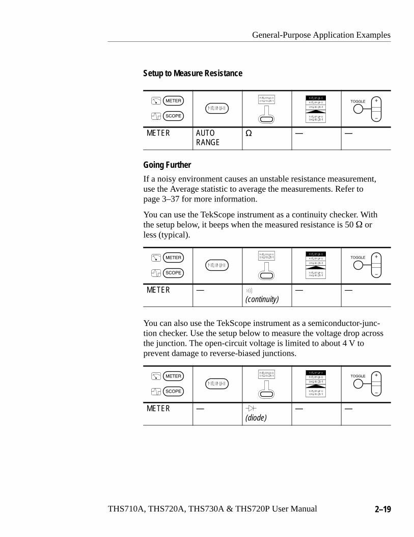
Setup to Measure Resistance
METER AUTORANGE
� — —
Going Further
If a noisy environment causes an unstable resistance measurement,use the Average statistic to average the measurements. Refer topage 3–37 for more information.
You can use the TekScope instrument as a continuity checker. Withthe setup below, it beeps when the measured resistance is 50 � orless (typical).
METER —(continuity)
— —
You can also use the TekScope instrument as a semiconductor-junc-tion checker. Use the setup below to measure the voltage drop acrossthe junction. The open-circuit voltage is limited to about 4 V toprevent damage to reverse-biased junctions.
METER —(diode)
— —

General-Purpose Application Examples
2–20 THS710A, THS720A, THS730A & THS720P User Manual
Measuring the Frequency of a Clock SignalYou suspect that the frequency of a TTL clock signal is out oftolerance. Connect the TekScope instrument to the signal to displayit and measure its frequency.
Ch 1Freq
30.62 MHz
Ch 1
General-Purpose Application Examples
THS710A, THS720A, THS730A & THS720P User Manual 2–21
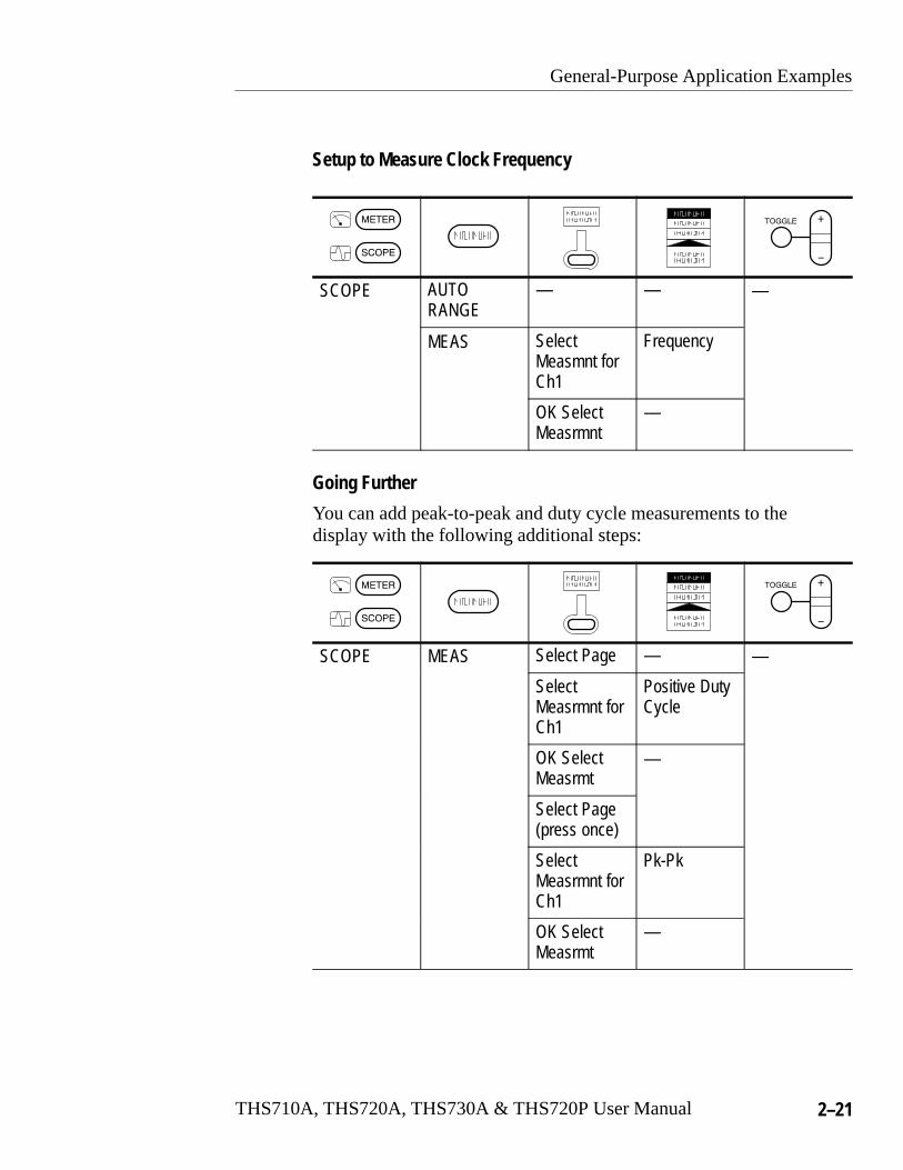
Setup to Measure Clock Frequency
SCOPE AUTORANGE
— — —
MEAS SelectMeasmnt forCh1
Frequency
OK SelectMeasrmnt
—
Going Further
You can add peak-to-peak and duty cycle measurements to thedisplay with the following additional steps:
SCOPE MEAS Select Page — —
SelectMeasrmnt forCh1
Positive DutyCycle
OK SelectMeasrmt
—
Select Page(press once)
SelectMeasrmnt forCh1
Pk-Pk
OK SelectMeasrmt
—
General-Purpose Application Examples
2–22 THS710A, THS720A, THS730A & THS720P User Manual
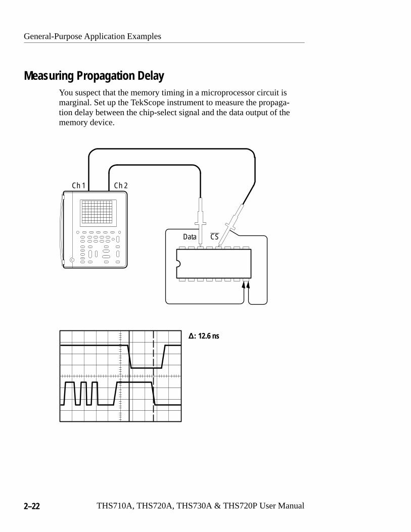
Measuring Propagation DelayYou suspect that the memory timing in a microprocessor circuit ismarginal. Set up the TekScope instrument to measure the propaga-tion delay between the chip-select signal and the data output of thememory device.
�� 12.6 ns
Ch 1 Ch 2
Data CS
General-Purpose Application Examples
THS710A, THS720A, THS730A & THS720P User Manual 2–23
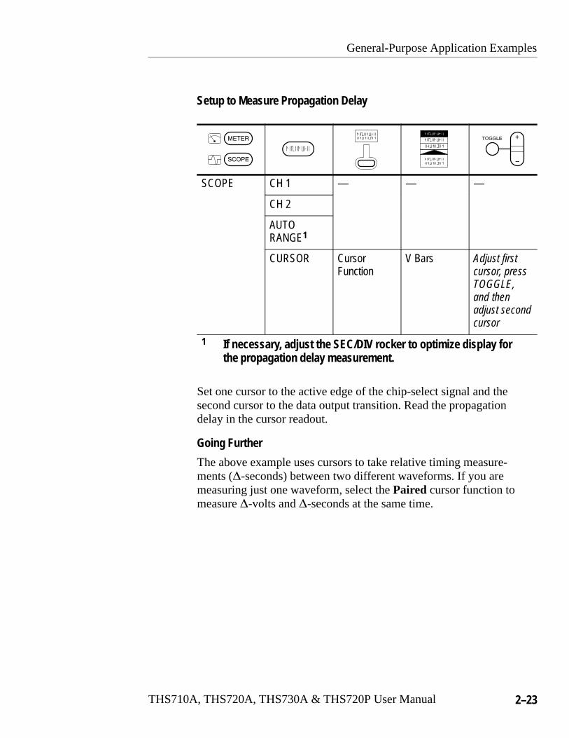
Setup to Measure Propagation Delay
SCOPE CH 1 — — —
CH 2
AUTORANGE1
CURSOR CursorFunction
V Bars Adjust firstcursor, pressTOGGLE,and thenadjust secondcursor
1 If necessary, adjust the SEC/DIV rocker to optimize display forthe propagation delay measurement.
Set one cursor to the active edge of the chip-select signal and thesecond cursor to the data output transition. Read the propagationdelay in the cursor readout.
Going Further
The above example uses cursors to take relative timing measure-ments (�-seconds) between two different waveforms. If you aremeasuring just one waveform, select the Paired cursor function tomeasure �-volts and �-seconds at the same time.

General-Purpose Application Examples
2–24 THS710A, THS720A, THS730A & THS720P User Manual
Triggering on a Missing Data PulseA positive-going TTL data pulse, 20 �s wide, should occur at leastonce every millisecond. The circuit is not working correctly and yoususpect an occasional missing pulse. Set up the TekScope instrumentto find the missing pulse.
Ch 1
General-Purpose Application Examples
THS710A, THS720A, THS730A & THS720P User Manual 2–25
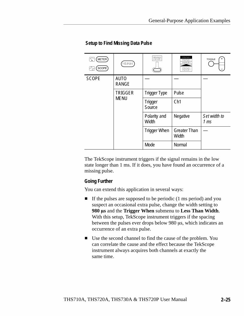
Setup to Find Missing Data Pulse
SCOPE AUTORANGE
— — —
TRIGGERNU
Trigger Type PulseMENU
TriggerSource
Ch1
Polarity andWidth
Negative Set width to1 ms
Trigger When Greater ThanWidth
—
Mode Normal
The TekScope instrument triggers if the signal remains in the lowstate longer than 1 ms. If it does, you have found an occurrence of amissing pulse.
Going Further
You can extend this application in several ways:
� If the pulses are supposed to be periodic (1 ms period) and yoususpect an occasional extra pulse, change the width setting to980 �s and the Trigger When submenu to Less Than Width.With this setup, TekScope instrument triggers if the spacingbetween the pulses ever drops below 980 �s, which indicates anoccurrence of an extra pulse.
� Use the second channel to find the cause of the problem. Youcan correlate the cause and the effect because the TekScopeinstrument always acquires both channels at exactly thesame time.

General-Purpose Application Examples
2–26 THS710A, THS720A, THS730A & THS720P User Manual
Detecting Narrow GlitchesAn elapsed-time counter circuit operates from a precision, 1 kHzsquare wave, clock signal supplied by another source. Occasionally,the counter counts too fast. You suspect glitches in the clock signalare causing the problem. Set up the TekScope instrument to look forglitches in the clock signal.
Ch 1
General-Purpose Application Examples
THS710A, THS720A, THS730A & THS720P User Manual 2–27
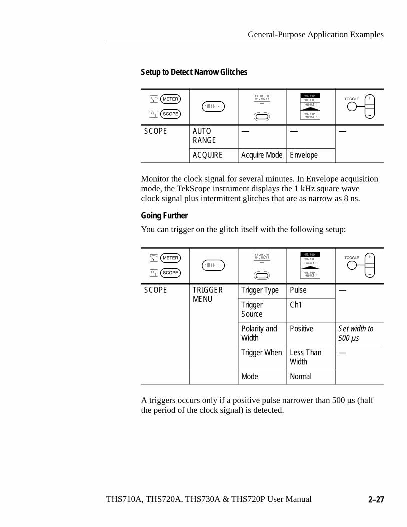
Setup to Detect Narrow Glitches
SCOPE AUTORANGE
— — —
ACQUIRE Acquire Mode Envelope
Monitor the clock signal for several minutes. In Envelope acquisitionmode, the TekScope instrument displays the 1 kHz square waveclock signal plus intermittent glitches that are as narrow as 8 ns.
Going Further
You can trigger on the glitch itself with the following setup:
SCOPE TRIGGERNU
Trigger Type Pulse —MENU
TriggerSource
Ch1
Polarity andWidth
Positive Set width to500 �s
Trigger When Less ThanWidth
—
Mode Normal
A triggers occurs only if a positive pulse narrower than 500 �s (halfthe period of the clock signal) is detected.

General-Purpose Application Examples
2–28 THS710A, THS720A, THS730A & THS720P User Manual
Triggering on a Third SignalA metal forming machine produces an index pulse for eachrevolution of its main shaft. Connect the external trigger input of theTekScope instrument to the index pulse so you can monitor theoutput of two transducers while you vary the operating speed of themachine.
Ch 1 Ch 2
Transducer #1 (Ch 1)
Transducer #2 (Ch 2)
Externaltrigger signal
COM
DMM

General-Purpose Application Examples
THS710A, THS720A, THS730A & THS720P User Manual 2–29
Setup to Use External Trigger
SCOPE TRIGGERNU
Trigger Type Edge —MENU
TriggerSource
External
Connect the index pulse to the meter inputs, which now function asthe external trigger input. Adjust the TRIGGER LEVEL rocker forstable triggering on the index pulse signal.
Going Further
You can use the external trigger input to trigger on a 50 Hz or 60 HzAC power line. This leaves the two channel inputs free to probeother circuits that are synchronized to the AC power line. Set theexternal trigger level to 0.2 V to trigger as close as possible to a zerocrossing.

General-Purpose Application Examples
2–30 THS710A, THS720A, THS730A & THS720P User Manual
Analyzing a Serial Data Communication LinkYou are having intermittent problems with a serial data communica-tion link and you suspect poor signal quality. Set up the TekScopeinstrument to show you a snapshot of the serial data stream so youcan verify the signal levels and transition times.
Ch 1
General-Purpose Application Examples
THS710A, THS720A, THS730A & THS720P User Manual 2–31
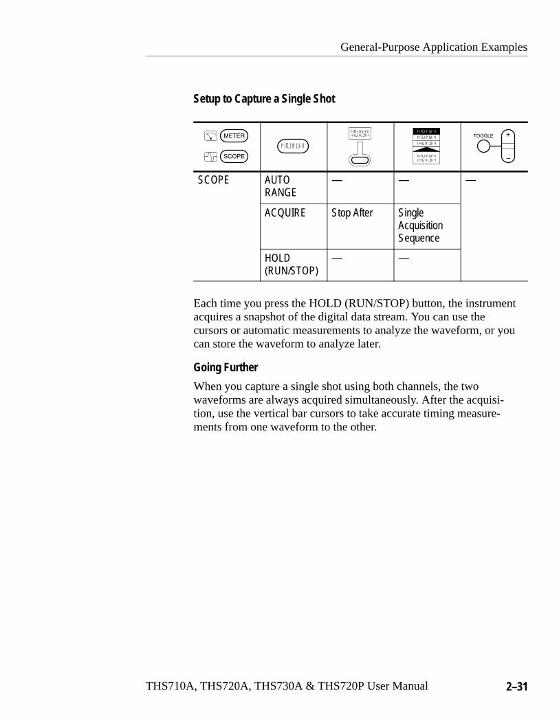
Setup to Capture a Single Shot
SCOPE AUTORANGE
— — —
ACQUIRE Stop After SingleAcquisitionSequence
HOLD(RUN/STOP)
— —
Each time you press the HOLD (RUN/STOP) button, the instrumentacquires a snapshot of the digital data stream. You can use thecursors or automatic measurements to analyze the waveform, or youcan store the waveform to analyze later.
Going Further
When you capture a single shot using both channels, the twowaveforms are always acquired simultaneously. After the acquisi-tion, use the vertical bar cursors to take accurate timing measure-ments from one waveform to the other.

General-Purpose Application Examples
2–32 THS710A, THS720A, THS730A & THS720P User Manual
Triggering on a Video SignalThe image quality is poor on a video monitor in a closed-circuitsecurity system that uses the NTSC broadcast standard. Set up theTekScope instrument to display and trigger on the odd field of thevideo waveform coming into the monitor.
Ch 1
Incoming video signal
75 � terminator
General-Purpose Application Examples
THS710A, THS720A, THS730A & THS720P User Manual 2–33
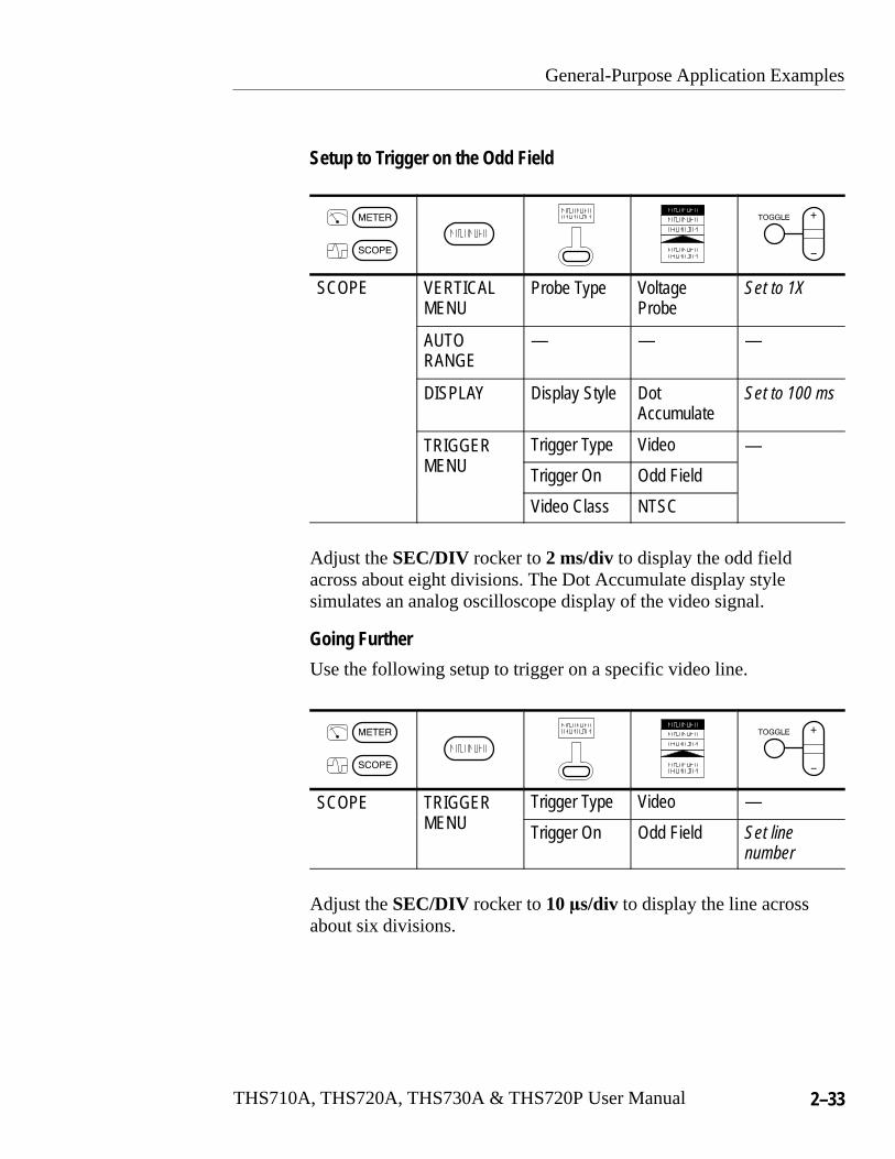
Setup to Trigger on the Odd Field
SCOPE VERTICALMENU
Probe Type VoltageProbe
Set to 1X
AUTORANGE
— — —
DISPLAY Display Style Dot Accumulate
Set to 100 ms
TRIGGERNU
Trigger Type Video —MENU Trigger On Odd Field
Video Class NTSC
Adjust the SEC/DIV rocker to 2 ms/div to display the odd fieldacross about eight divisions. The Dot Accumulate display stylesimulates an analog oscilloscope display of the video signal.
Going Further
Use the following setup to trigger on a specific video line.
SCOPE TRIGGERNU
Trigger Type Video —MENU Trigger On Odd Field Set line
number
Adjust the SEC/DIV rocker to 10 �s/div to display the line acrossabout six divisions.

General-Purpose Application Examples
2–34 THS710A, THS720A, THS730A & THS720P User Manual
THS710A, THS720A, THS730A & THS720P User Manual 2–35
Power-Measurement Application Examples
This section presents a series of power-measurement applicationexamples. These simplified examples highlight the features of theTekScope instrument and give you ideas about using it to solve yourown test problems.
These examples provide an overview of applications that cover thefollowing areas:
� Power electronics testing
� Power quality testing
� Motor testing
NOTE. Some of these application examples require optional probes.Others highlight features only available in the THS720P.

Power-Measurement Application Examples
2–36 THS710A, THS720A, THS730A & THS720P User Manual
Testing a Switching Transistor Drive CircuitYou need to evaluate the gate-drive circuit for a power FET(field-effect transistor) in a switching power supply. The gate-drivetiming circuit is referenced to chassis ground. But the gate-drivesignal is transformer-coupled to the FET, which is connected to a–300 VDC bus. Set up the TekScope instrument to compare thegate-drive signal at the output of the timing circuit to the signal atthe gate of the FET.
Timingcircuit
Ch 1 Ch 2
–300 VDC bus
P5102Probe

Power-Measurement Application Examples
THS710A, THS720A, THS730A & THS720P User Manual 2–37
Setup to Test the Transistor Drive Circuit
SCOPE CH 1 — — —
CH 2
AUTORANGE
You do not have to do anything special to take this difficultmeasurement. Because of the isolated channels, you can referencethe channel 1 probe to chassis ground and the channel 2 probedirectly to the –300 VDC bus. Channel 1 displays the gate-drivesignal directly from the driver and channel 2 displays the signal as itis received by the power FET.
Going Further
The isolated channels allow you to reference a channel to AC as wellas DC voltages.
� You can connect the P5102 probe reference lead to 50 Hz, 60 Hz,or 400 Hz AC power lines (up to the maximum voltage rating).
� You can connect the P6117 or P5102 probe reference lead tomany other dynamic signals (up to the maximum voltage rating).
Because you can connect to references other than ground, you cantake many measurements that would otherwise require an oscillo-scope with a differential input.
Power-Measurement Application Examples
2–38 THS710A, THS720A, THS730A & THS720P User Manual
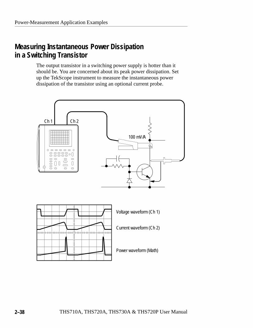
Measuring Instantaneous Power Dissipationin a Switching Transistor
The output transistor in a switching power supply is hotter than itshould be. You are concerned about its peak power dissipation. Setup the TekScope instrument to measure the instantaneous powerdissipation of the transistor using an optional current probe.
Ch 1 Ch 2
Voltage waveform (Ch 1)
Current waveform (Ch 2)
Power waveform (Math)
100 mV/A

Power-Measurement Application Examples
THS710A, THS720A, THS730A & THS720P User Manual 2–39
Setup to Measure Instantaneous Power Dissipation
SCOPE CH 1 — — —
CH 2 Probe Type CurrentProbe
Set to100 mV/A
AUTORANGE
— — —
MATH MathOperation
Ch1 × Ch2
CURSOR CursorFunction
Paired Set cursor
Move the cursor along the power (MATH) waveform and read theinstantaneous power in the cursor readout (for example, @5.63 W).
Going Further
Measure the average power dissipation in the transistor (mean valueof the power waveform) with the following setup:
SCOPE MEAS SelectMeasrmnt forMATH
Mean —
OK SelectMeasrmnt
—
You can also display the I-V characteristic of the transistor forcomparison to its safe operating area using the XY display format.Refer to page 3–14 for information on XY display format.

Power-Measurement Application Examples
2–40 THS710A, THS720A, THS730A & THS720P User Manual
Monitoring for Power Surges and DropoutsYou are having intermittent problems with some electronicequipment that operates unattended at a remote site. You need todetermine if the problem might be caused by momentary powerquality problems in the electrical service to the equipment. Set upthe TekScope instrument to monitor the line voltage for a week andcapture any surges or dropouts that may occur.
8 days
Remote site
Power-Measurement Application Examples
THS710A, THS720A, THS730A & THS720P User Manual 2–41
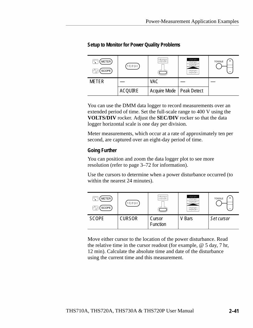
Setup to Monitor for Power Quality Problems
METER — VAC — —
ACQUIRE Acquire Mode Peak Detect
You can use the DMM data logger to record measurements over anextended period of time. Set the full-scale range to 400 V using theVOLTS/DIV rocker. Adjust the SEC/DIV rocker so that the datalogger horizontal scale is one day per division.
Meter measurements, which occur at a rate of approximately ten persecond, are captured over an eight-day period of time.
Going Further
You can position and zoom the data logger plot to see moreresolution (refer to page 3–72 for information).
Use the cursors to determine when a power disturbance occurred (towithin the nearest 24 minutes).
SCOPE CURSOR CursorFunction
V Bars Set cursor
Move either cursor to the location of the power disturbance. Readthe relative time in the cursor readout (for example, @ 5 day, 7 hr,12 min). Calculate the absolute time and date of the disturbanceusing the current time and this measurement.
Power-Measurement Application Examples
2–42 THS710A, THS720A, THS730A & THS720P User Manual
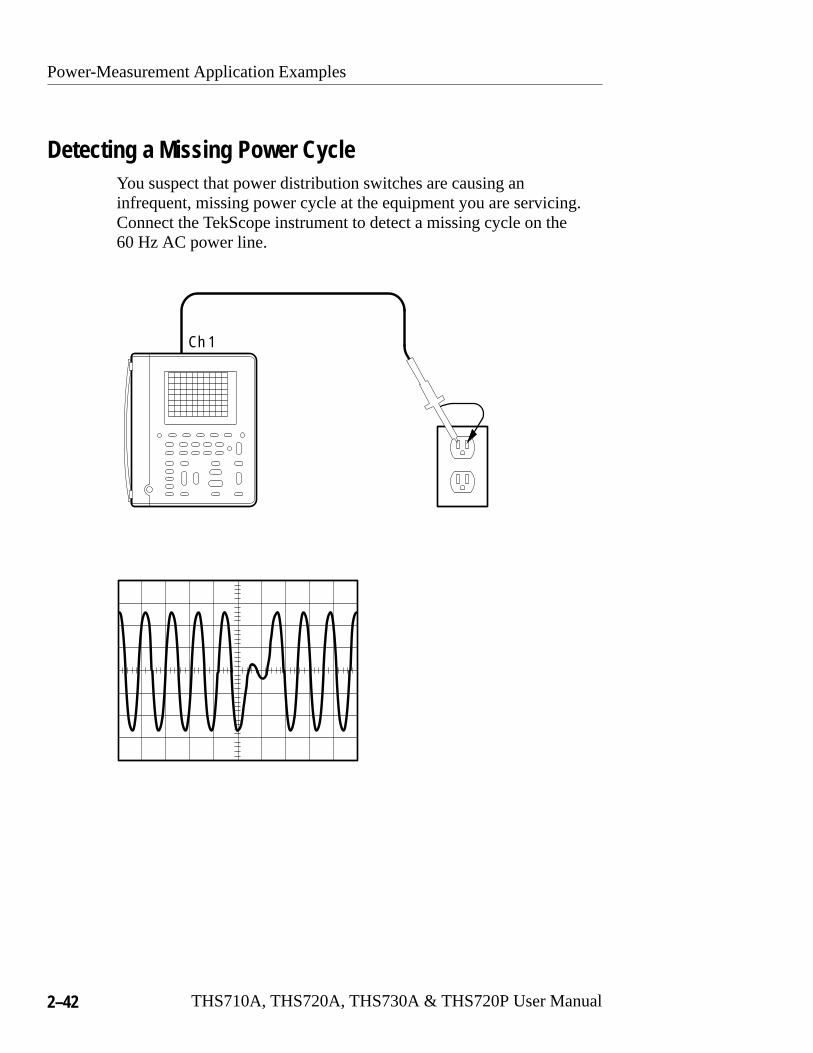
Detecting a Missing Power CycleYou suspect that power distribution switches are causing aninfrequent, missing power cycle at the equipment you are servicing.Connect the TekScope instrument to detect a missing cycle on the60 Hz AC power line.
Ch 1

Power-Measurement Application Examples
THS710A, THS720A, THS730A & THS720P User Manual 2–43
Setup to Detect a Missing Cycle
SCOPE AUTORANGE
— — —
TRIGGERNU
Trigger Type PulseMENU
TriggerSource
Ch1
Polarity andWidth
Negative Set width to20 ms
Trigger When Greater ThanWidth
—
Mode Normal
Set the trigger level to +50 V. The TekScope instrument triggers ifone or more power cycles drop below a 50 Vpk threshold. You canset the voltage threshold to any other level that constitutes a powerdropout.
Going Further
Use the other channel to analyze the effect that the missing cycle hason your equipment:
� Momentary sags in internal power-supply voltages
� Malfunctions in digital circuitry
� Variations in clock frequencies
Channel 1 and channel 2 are always acquired simultaneously so youcan correlate a cause displayed on one channel to the effectdisplayed on the other.
Power-Measurement Application Examples
2–44 THS710A, THS720A, THS730A & THS720P User Manual
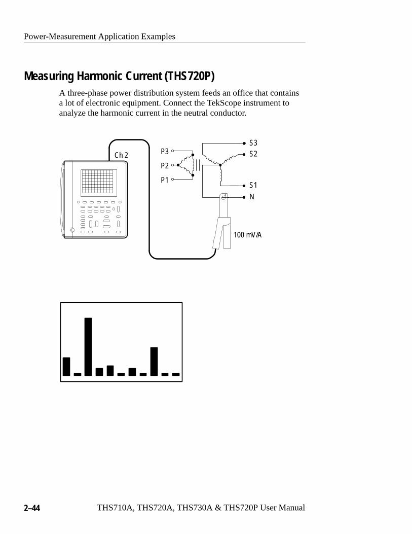
Measuring Harmonic Current (THS720P)A three-phase power distribution system feeds an office that containsa lot of electronic equipment. Connect the TekScope instrument toanalyze the harmonic current in the neutral conductor.
P1
P2
P3
S1
S2S3
N
Ch 2
100 mV/A
Power-Measurement Application Examples
THS710A, THS720A, THS730A & THS720P User Manual 2–45
Setup to Measure Harmonic Current
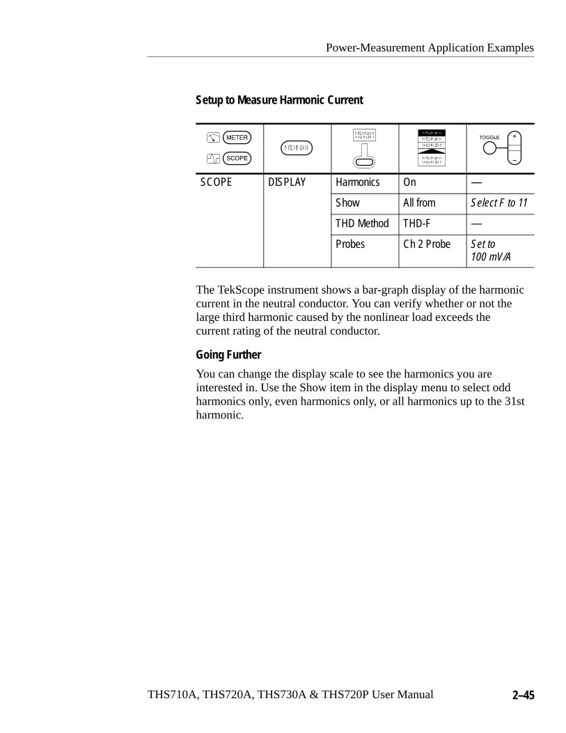
SCOPE DISPLAY Harmonics On —
Show All from Select F to 11
THD Method THD-F —
Probes Ch 2 Probe Set to100 mV/A
The TekScope instrument shows a bar-graph display of the harmoniccurrent in the neutral conductor. You can verify whether or not thelarge third harmonic caused by the nonlinear load exceeds thecurrent rating of the neutral conductor.
Going Further
You can change the display scale to see the harmonics you areinterested in. Use the Show item in the display menu to select oddharmonics only, even harmonics only, or all harmonics up to the 31stharmonic.
Power-Measurement Application Examples
2–46 THS710A, THS720A, THS730A & THS720P User Manual
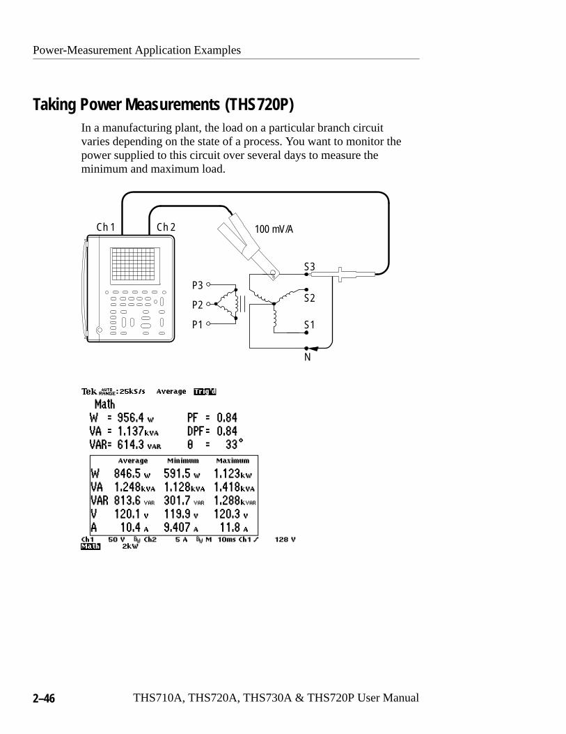
Taking Power Measurements (THS720P)In a manufacturing plant, the load on a particular branch circuitvaries depending on the state of a process. You want to monitor thepower supplied to this circuit over several days to measure theminimum and maximum load.
Ch 2Ch 1
P1
P2
P3
S1
S2
S3
N
100 mV/A

Power-Measurement Application Examples
THS710A, THS720A, THS730A & THS720P User Manual 2–47
Setup to Monitor Power
SCOPE DISPLAY Harmonics On —
Probes CurrentProbe CH 2
Set to100 mV/A
MATH — — —
The TekScope instrument continuously measures voltage andcurrent, and then calculates the power statistics shown in the box.Use the average, minimum, and maximum statistics to characterizethe load on this branch circuit.
Going Further
The numbers displayed above the box are instantaneous powermeasurements. You can use them to measure short-term variations.
The power statistics accumulate from the beginning of an acquisi-tion. To reset the statistics, press HOLD twice to stop and restart theacquisition.
Power-Measurement Application Examples
2–48 THS710A, THS720A, THS730A & THS720P User Manual
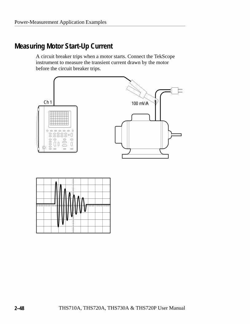
Measuring Motor Start-Up CurrentA circuit breaker trips when a motor starts. Connect the TekScopeinstrument to measure the transient current drawn by the motorbefore the circuit breaker trips.
Ch 1 100 mV/A

Power-Measurement Application Examples
THS710A, THS720A, THS730A & THS720P User Manual 2–49
Setup to Measure Transient Current
SCOPE CH 1 Probe Type CurrentProbe
Set to100 mV/A
ACQUIRE Stop After SingleAcquisitionSequence
—
HOLD(RUN/STOP)
— —
When you start the motor, the instrument captures the transientcurrent and freezes the waveform in the display.
Going Further
You can measure the true RMS current of the transient current usingthe following technique:
1. Turn on automated measurements for channel 1 and select theBrstW (burst width) and RMS measurements. Refer to page 3–31for infomation about automatic measurements.
2. Record the BrstW and RMS measurements.
3. Record the SEC/DIV setting.
4. Calculate the true RMS value of the transient current usingrecorded values in the one of the equations below:
True RMS� RMS� 10�SEC�DIV
BrstW�
True RMS� RMS� 100�SEC�DIV
BrstW�
(if MAG is off)
(if MAG is on)
Power-Measurement Application Examples
2–50 THS710A, THS720A, THS730A & THS720P User Manual
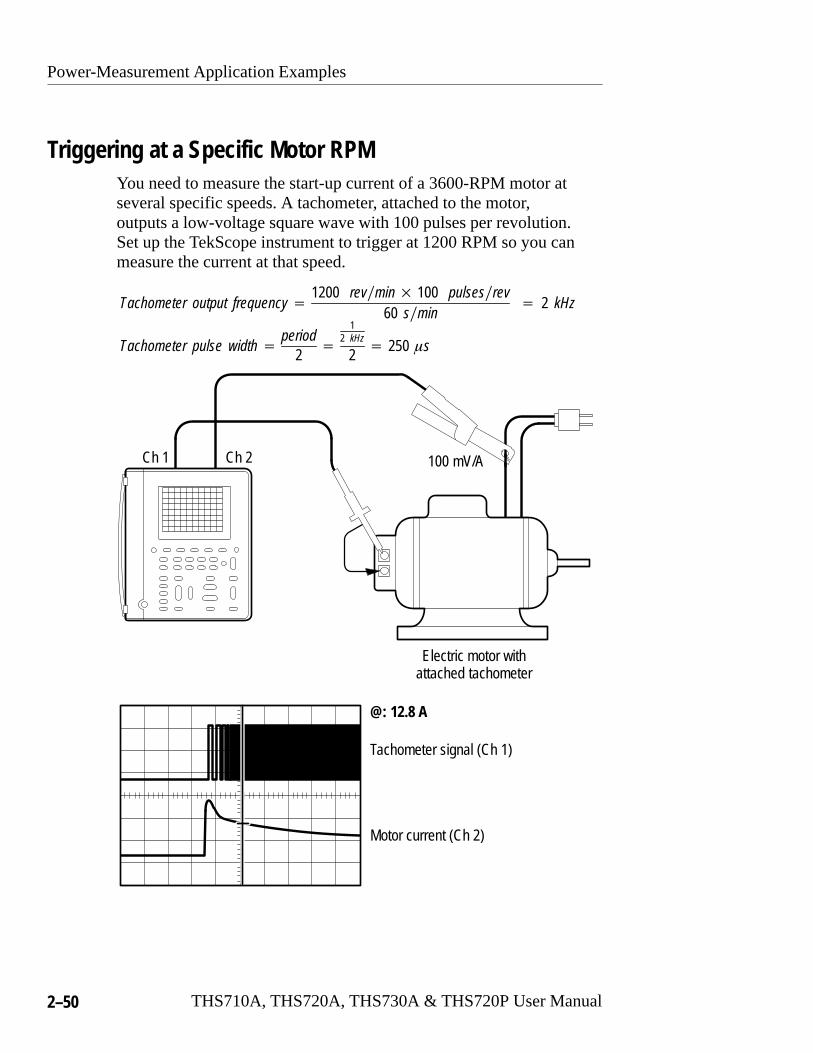
Triggering at a Specific Motor RPMYou need to measure the start-up current of a 3600-RPM motor atseveral specific speeds. A tachometer, attached to the motor,outputs a low-voltage square wave with 100 pulses per revolution.Set up the TekScope instrument to trigger at 1200 RPM so you canmeasure the current at that speed.
Ch 1 Ch 2
Tachometer output frequency�1200 rev�min� 100 pulses�rev
60 s�min� 2 kHz
Tachometer pulse width �period
2�
12 kHz
2� 250 �s
Electric motor withattached tachometer
Tachometer signal (Ch 1)
Motor current (Ch 2)
@: 12.8 A
100 mV/A
Power-Measurement Application Examples
THS710A, THS720A, THS730A & THS720P User Manual 2–51
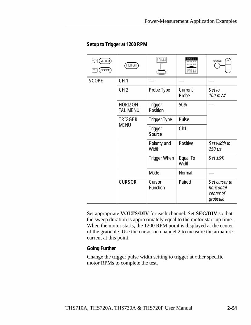
Setup to Trigger at 1200 RPM
SCOPE CH 1 — — —
CH 2 Probe Type CurrentProbe
Set to100 mV/A
HORIZON-TAL MENU
Trigger Position
50% —
TRIGGERNU
Trigger Type PulseMENU
TriggerSource
Ch1
Polarity andWidth
Positive Set width to250 �s
Trigger When Equal ToWidth
Set ±5%
Mode Normal —
CURSOR CursorFunction
Paired Set cursor tohorizontalcenter of graticule
Set appropriate VOLTS/DIV for each channel. Set SEC/DIV so thatthe sweep duration is approximately equal to the motor start-up time.When the motor starts, the 1200 RPM point is displayed at the centerof the graticule. Use the cursor on channel 2 to measure the armaturecurrent at this point.
Going Further
Change the trigger pulse width setting to trigger at other specificmotor RPMs to complete the test.

Power-Measurement Application Examples
2–52 THS710A, THS720A, THS730A & THS720P User Manual
Triggering on a Motor Drive Waveform (THS720P)You need to analyze the output waveform of a variable-speed ACmotor drive. Connect the TekScope instrument to trigger on theoutput waveform of the motor drive.
Ch 1
Motordrive
Power-Measurement Application Examples
THS710A, THS720A, THS730A & THS720P User Manual 2–53
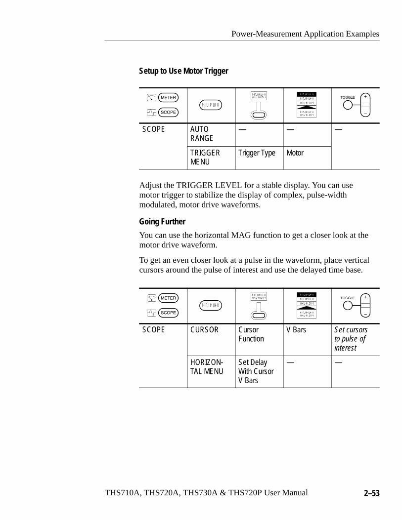
Setup to Use Motor Trigger
SCOPE AUTORANGE
— — —
TRIGGERMENU
Trigger Type Motor
Adjust the TRIGGER LEVEL for a stable display. You can usemotor trigger to stabilize the display of complex, pulse-widthmodulated, motor drive waveforms.
Going Further
You can use the horizontal MAG function to get a closer look at themotor drive waveform.
To get an even closer look at a pulse in the waveform, place verticalcursors around the pulse of interest and use the delayed time base.
SCOPE CURSOR Cursor Function
V Bars Set cursorsto pulse ofinterest
HORIZON-TAL MENU
Set DelayWith CursorV Bars
— —

Power-Measurement Application Examples
2–54 THS710A, THS720A, THS730A & THS720P User Manual

Reference

THS710A, THS720A, THS730A & THS720P User Manual 3–1
Introduction to Reference
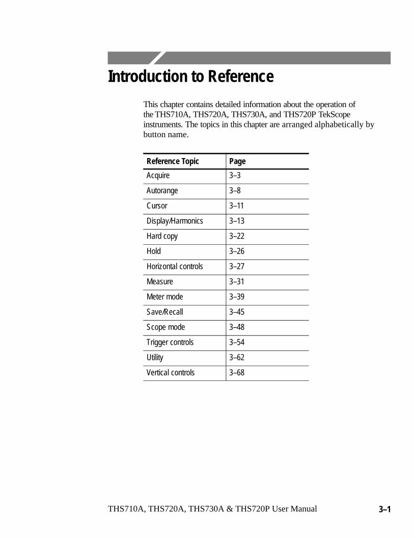
This chapter contains detailed information about the operation ofthe THS710A, THS720A, THS730A, and THS720P TekScopeinstruments. The topics in this chapter are arranged alphabetically bybutton name.
Reference Topic Page
Acquire 3–3
Autorange 3–8
Cursor 3–11
Display/Harmonics 3–13
Hard copy 3–22
Hold 3–26
Horizontal controls 3–27
Measure 3–31
Meter mode 3–39
Save/Recall 3–45
Scope mode 3–48
Trigger controls 3–54
Utility 3–62
Vertical controls 3–68

Introduction to Reference
3–2 THS710A, THS720A, THS730A & THS720P User Manual
ACQUIRE
THS710A, THS720A, THS730A & THS720P User Manual 3–3
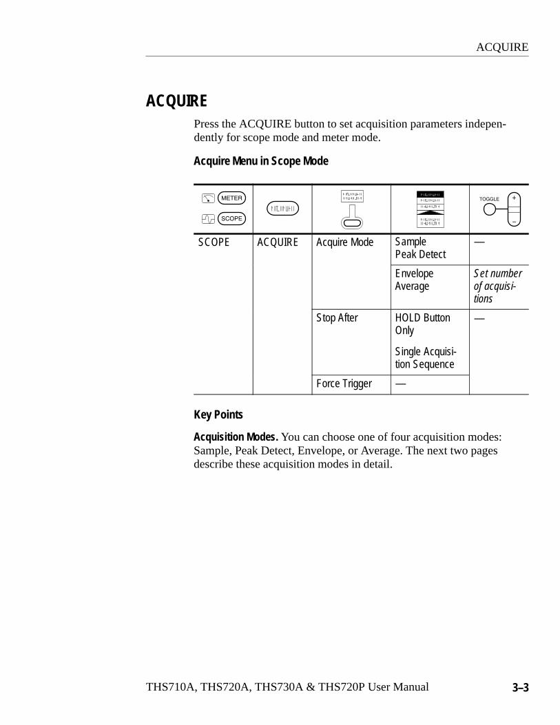
ACQUIREPress the ACQUIRE button to set acquisition parameters indepen-dently for scope mode and meter mode.
Acquire Menu in Scope Mode
SCOPE ACQUIRE Acquire Mode SamplePeak Detect
—
EnvelopeAverage
Set numberof acquisi-tions
Stop After HOLD ButtonOnly
Single Acquisi-tion Sequence
—
Force Trigger —
Key Points
Acquisition Modes. You can choose one of four acquisition modes:Sample, Peak Detect, Envelope, or Average. The next two pagesdescribe these acquisition modes in detail.
ACQUIRE
3–4 THS710A, THS720A, THS730A & THS720P User Manual
Samples acquired in fouracquisition intervals
Displayed recordpoints
Acquisitionmode
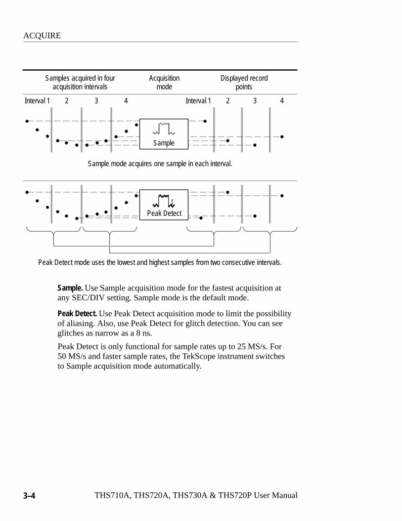
Sample mode acquires one sample in each interval.
Peak Detect
Interval 1 2 3 4 Interval 1 2 3 4
Peak Detect mode uses the lowest and highest samples from two consecutive intervals.
Sample
Sample. Use Sample acquisition mode for the fastest acquisition atany SEC/DIV setting. Sample mode is the default mode.
Peak Detect. Use Peak Detect acquisition mode to limit the possibilityof aliasing. Also, use Peak Detect for glitch detection. You can seeglitches as narrow as a 8 ns.
Peak Detect is only functional for sample rates up to 25 MS/s. For50 MS/s and faster sample rates, the TekScope instrument switchesto Sample acquisition mode automatically.

ACQUIRE
THS710A, THS720A, THS730A & THS720P User Manual 3–5
Calculates average valuefor each record point over
many acquisitions
Envelope
Average
Acquisition 1 2 3
Three acquisitions from one source Acquisition mode
Envelope uses Peak Detect modefor each individual acquisition.
Average uses Sample mode foreach individual acquisition.
Finds highest and lowest record points over
many acquisitions
Envelope and Average. Use Envelope acquisition mode to capturevariations of a signal over a longer period of time. Use Averageacquisition mode to reduce random or uncorrelated noise in thesignal you want to display.
The +/– rocker sets a specific number of acquisitions (N) to includein the enveloped or averaged waveform.
� The enveloped waveform clears and then starts over afterN acquisitions.
� The averaged waveform is a running average over N acquisitions.
� If you select Stop After Single Acquisition Sequence, anenvelope or average acquisition stops after N acquisitions.
ACQUIRE
3–6 THS710A, THS720A, THS730A & THS720P User Manual
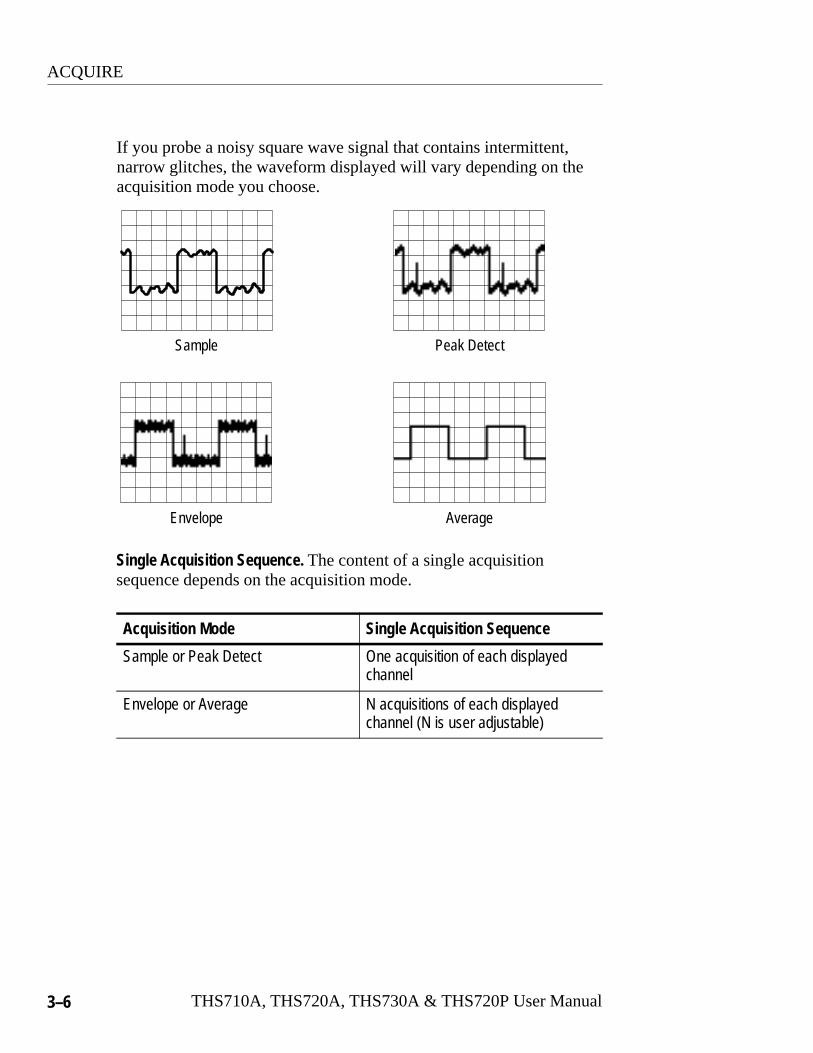
If you probe a noisy square wave signal that contains intermittent,narrow glitches, the waveform displayed will vary depending on theacquisition mode you choose.
Sample Peak Detect
Envelope Average
Single Acquisition Sequence. The content of a single acquisitionsequence depends on the acquisition mode.
Acquisition Mode Single Acquisition Sequence
Sample or Peak Detect One acquisition of each displayedchannel
Envelope or Average N acquisitions of each displayedchannel (N is user adjustable)
ACQUIRE
THS710A, THS720A, THS730A & THS720P User Manual 3–7
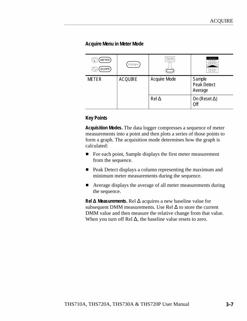
Acquire Menu in Meter Mode
METER ACQUIRE Acquire Mode SamplePeak DetectAverage
Rel � On (Reset �)Off
Key Points
Acquisition Modes. The data logger compresses a sequence of metermeasurements into a point and then plots a series of those points toform a graph. The acquisition mode determines how the graph iscalculated:
� For each point, Sample displays the first meter measurementfrom the sequence.
� Peak Detect displays a column representing the maximum andminimum meter measurements during the sequence.
� Average displays the average of all meter measurements duringthe sequence.
Rel � Measurements. Rel � acquires a new baseline value forsubsequent DMM measurements. Use Rel � to store the currentDMM value and then measure the relative change from that value.When you turn off Rel �� the baseline value resets to zero.

AUTORANGE
3–8 THS710A, THS720A, THS730A & THS720P User Manual
AUTORANGEAutorange automatically adjusts setup values to track a signal. If thesignal changes, the setup continues to change to track the signal.Autorange works independently in scope and meter modes. Refer topage 3–16 for additional autorange information for the THS720P.
The following controls are preset when you first select the autorangefunction.
Scope Mode Meter Mode
Acquire mode: Sample none
Stop acquire after: HOLD button only
Vertical coupling: DC (if GND wasselected)
Bandwidth: Full
Invert: Off
Horizontal position: Centered
Horizontal magnification: Off
Trigger type: Edge
Trigger source: Lowest numberedchannel displayed
Trigger coupling: DC
Trigger slope: Positive
Trigger holdoff: Minimum
Display style: Vectors
Display format: YT
AUTORANGE
THS710A, THS720A, THS730A & THS720P User Manual 3–9
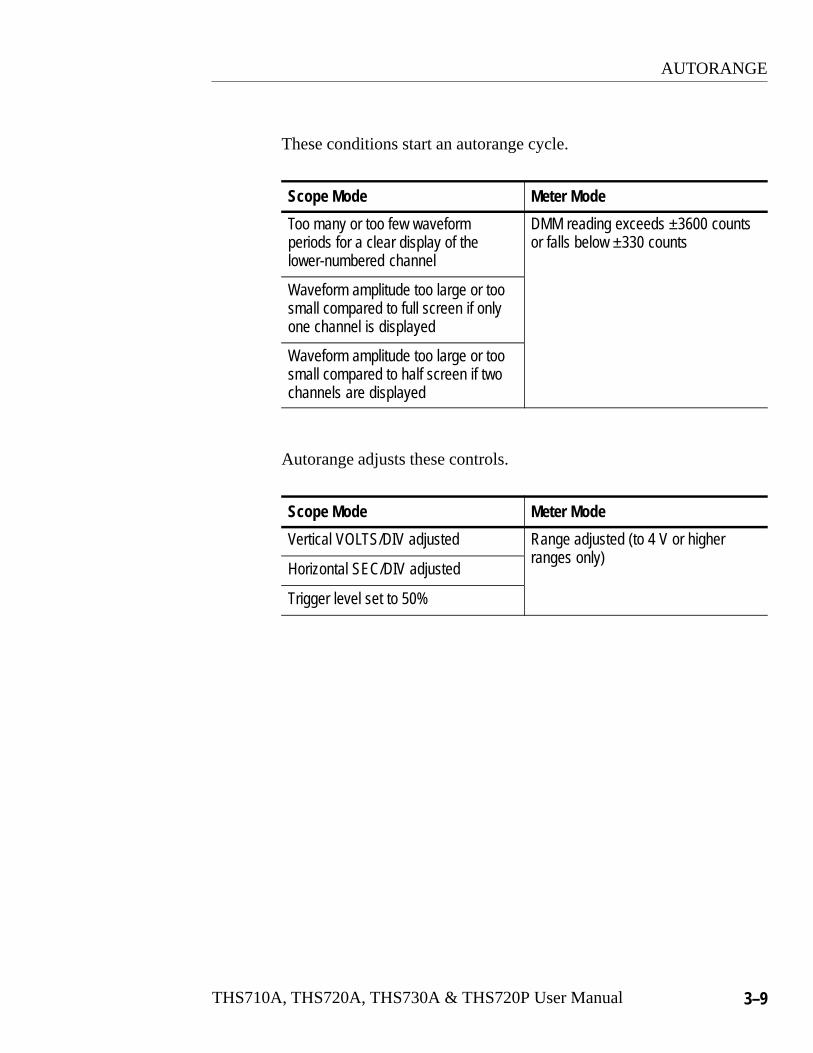
These conditions start an autorange cycle.
Scope Mode Meter Mode
Too many or too few waveformperiods for a clear display of thelower-numbered channel
DMM reading exceeds ±3600 countsor falls below ±330 counts
Waveform amplitude too large or toosmall compared to full screen if onlyone channel is displayed
Waveform amplitude too large or toosmall compared to half screen if twochannels are displayed
Autorange adjusts these controls.
Scope Mode Meter Mode
Vertical VOLTS/DIV adjusted Range adjusted (to 4 V or higherr es
Horizontal SEC/DIV adjustedranges only)
Trigger level set to 50%

AUTORANGE
3–10 THS710A, THS720A, THS730A & THS720P User Manual
These control changes turn off autorange.
Scope Mode Meter Mode
Change to Stop After Single Acquisi-tion Sequence
Change range (VOLTS/DIV)
Change VOLTS/DIV
Change SEC/DIV
Change trigger type
Change trigger level
Change trigger coupling
Change trigger holdoff
Change display format to XY
Change display style

CURSOR
THS710A, THS720A, THS730A & THS720P User Manual 3–11
CURSORPress the CURSOR button to display the cursor menu. In scopemode, cursors operate on the 2500-point record of the selectedwaveform. In meter mode, they operate on the 250-point datalogger plot.
SCOPE CURSOR Cursor Function OffH BarsV BarsPaired
Time Units Seconds1/seconds (Hz)Degrees
Set 0� and 360�with V Bars
—
METER CURSOR Cursor Function OffH BarsV BarsPaired
Key Points
Cursor Movement. Use the +/– rocker to move the active cursor. Pressthe TOGGLE button to change which cursor is active.
Fine Cursor Movement. If you first press MAG, you can set a cursor toany point in the 2500-point oscilloscope waveform.
Cursor Functions. H Bars measure voltage. V Bars measure time,frequency, or degrees. Paired measures both voltage and time,voltage and frequency, or voltage and degrees.

CURSOR
3–12 THS710A, THS720A, THS730A & THS720P User Manual
Measuring Phase. Move the V Bar cursors to the 0° and 360° pointsand then press the Set 0° and 360° with V Bars button. Next, moveeither cursor to the point you want to measure.
Horizontal Bar cursors
Vertical Bar cursors
Paired cursors
� 4.16 V@ –1.78 V
� 6.12 �s@ 1.06 �s
� 6.32 V� 5.86 �s@ 3.16 V
@ Readout. For V Bar cursors, the readout after the @ symbolindicates the location of the active cursor relative to the trigger point.For degrees measurements, the readout is relative to the 0� and 360�points that you set. For H Bars or Paired cursors, it indicates thelocation relative to zero volts.
DISPLAY/HARMONICS
THS710A, THS720A, THS730A & THS720P User Manual 3–13
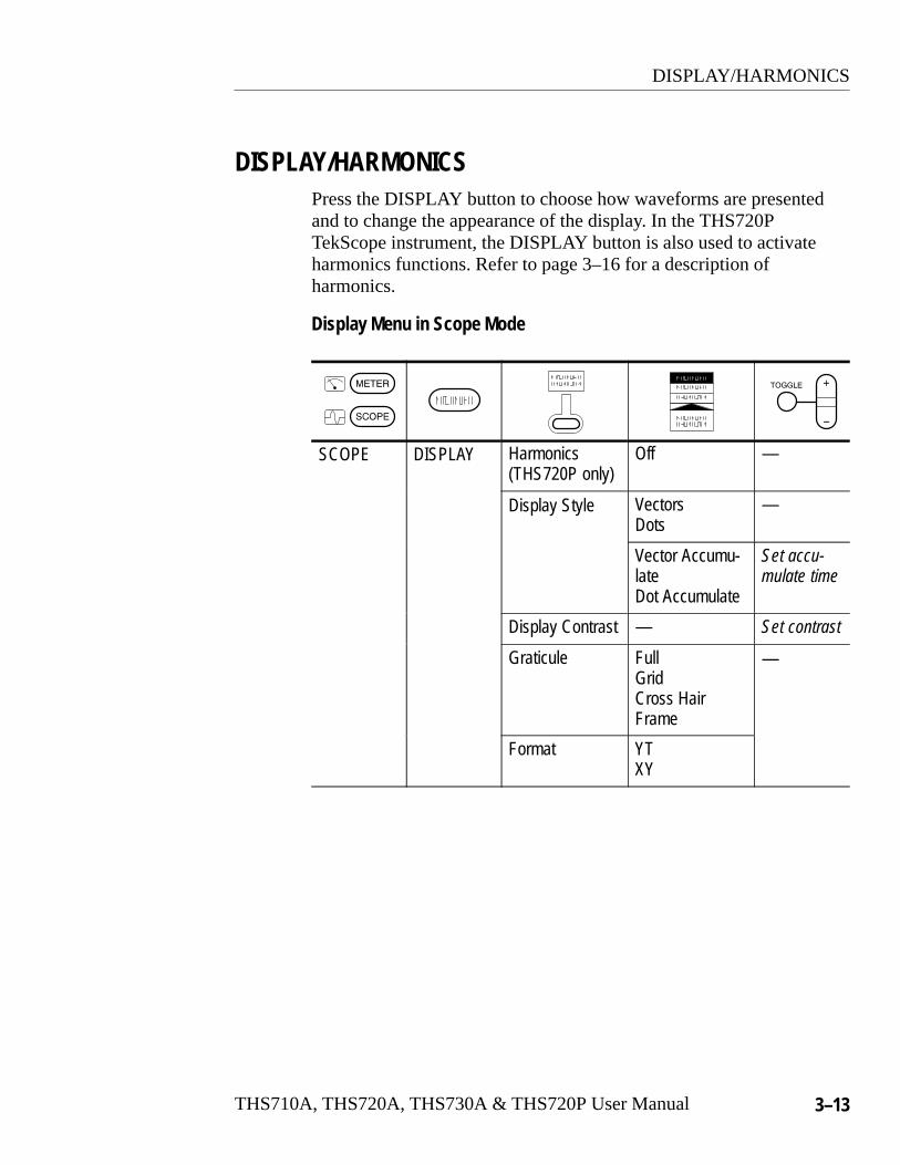
DISPLAY/HARMONICSPress the DISPLAY button to choose how waveforms are presentedand to change the appearance of the display. In the THS720PTekScope instrument, the DISPLAY button is also used to activateharmonics functions. Refer to page 3–16 for a description ofharmonics.
Display Menu in Scope Mode
SCOPE DISPLAY Harmonics(THS720P only)
Off —
Display Style Vectors Dots
—
Vector Accumu-lateDot Accumulate
Set accu-mulate time
Display Contrast — Set contrast
Graticule FullGridCross HairFrame
—
Format YTXY

DISPLAY/HARMONICS
3–14 THS710A, THS720A, THS730A & THS720P User Manual
Key Points
Display Style. Choose one of the following waveform display styles:
� Vectors fills the space between adjacent sample points inthe display. Widely spaced points are filled using (sin x)/xinterpolation.
� Dots displays only the individual sample points.
� Vector Accumulate adds persistence to the vector display. Usethe +/– rocker to set the accumulate time.
� Dot Accumulate adds persistence to the dot display. Use the+/– rocker to set the accumulate time.
NOTE. Vector Accumulate and Dot Accumulate are display functionsonly. When you change most control settings, the accumulated datais cleared. Accumulated waveforms cannot be saved.
XY Format. Choose XY display format when you want to displaychannel 1 in the horizontal axis and channel 2 in the vertical axis.The controls operate as follows:
� The channel 1 VOLTS/DIV and vertical POSITION controls nowset the horizontal scale and position.
� The channel 2 VOLTS/DIV and vertical POSITION controlscontinue to set vertical scale and position.
� The SEC/DIV and horizontal POSITION controls affect the timebase and the portion of the waveform that is displayed.

DISPLAY/HARMONICS
THS710A, THS720A, THS730A & THS720P User Manual 3–15
NOTE. The above XY-display example shows the I-V characteristic ofa switching power MOSFET. The current waveform, displayed in thevertical axis, is measured using a Tektronix A6302 current probe andAM503B current-probe amplifier.
The following functions do not work in XY display format:
� Ref or Math waveforms
� Cursors
� Horizontal MAG
� Autorange (resets display format to YT)
DISPLAY/HARMONICS
3–16 THS710A, THS720A, THS730A & THS720P User Manual
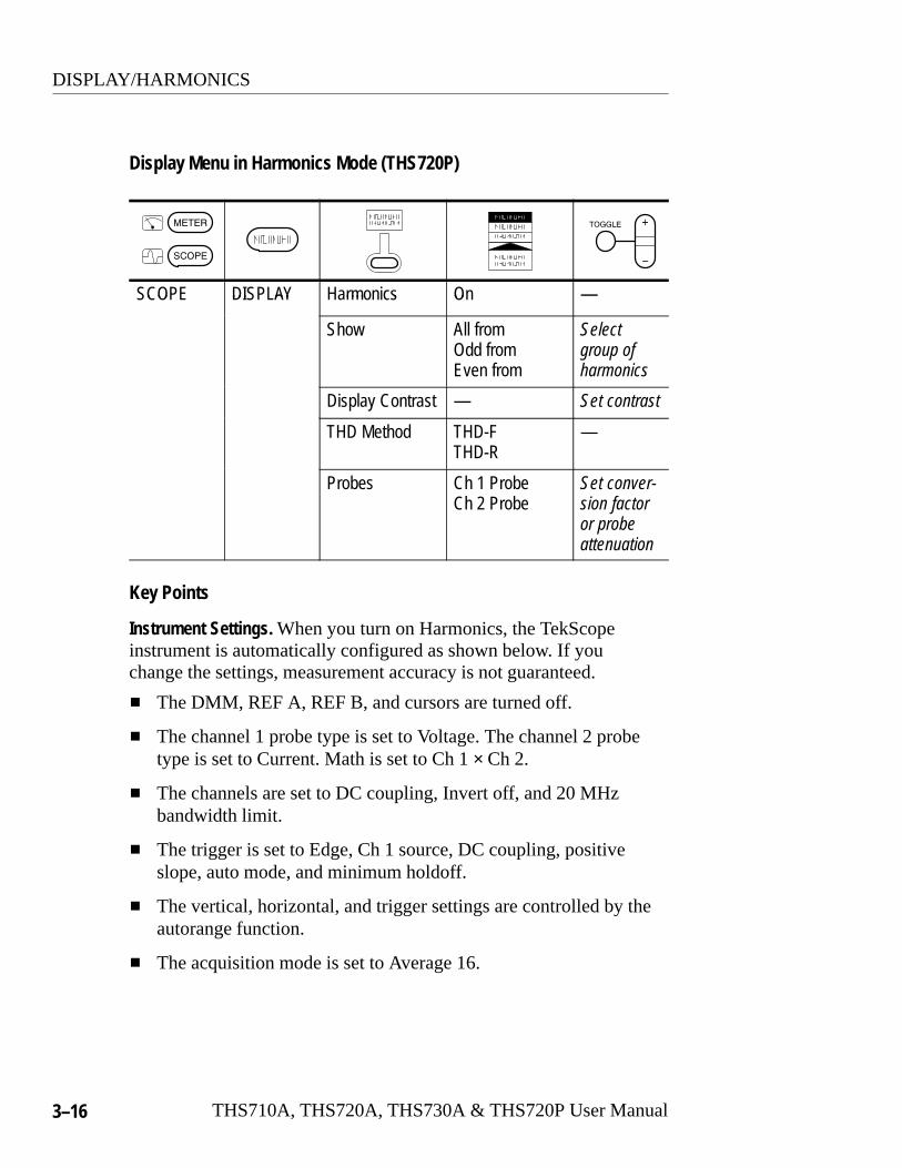
Display Menu in Harmonics Mode (THS720P)
CO DI AY rm s O —SCOPE DISPLAY Harmonics On —
Show All fromOdd fromEven from
Selectgroup ofharmonics
Display Contrast — Set contrast
THD Method THD-FTHD-R
—
Probes Ch 1 ProbeCh 2 Probe
Set conver-sion factoror probe attenuation
Key Points
Instrument Settings. When you turn on Harmonics, the TekScopeinstrument is automatically configured as shown below. If youchange the settings, measurement accuracy is not guaranteed.
� The DMM, REF A, REF B, and cursors are turned off.
� The channel 1 probe type is set to Voltage. The channel 2 probetype is set to Current. Math is set to Ch 1 × Ch 2.
� The channels are set to DC coupling, Invert off, and 20 MHzbandwidth limit.
� The trigger is set to Edge, Ch 1 source, DC coupling, positiveslope, auto mode, and minimum holdoff.
� The vertical, horizontal, and trigger settings are controlled by theautorange function.
� The acquisition mode is set to Average 16.

DISPLAY/HARMONICS
THS710A, THS720A, THS730A & THS720P User Manual 3–17
THD Calculation. Choose THD Method to specify whether TotalHarmonic Distortion is calculated relative to the fundamental or tothe RMS of the input signal.
Harmonics Display (THS720P)
Press CH 1 to display the voltage harmonics or press CH 2 to displaythe current harmonics. The harmonics display, shown below, isdivided into five sections. The next three pages identify the contentof each section in detail.
Waveform readout lines
Measurementreadout area
Status line
Graticulearea
Harmonicmeasurements
Press MATH to display the power measurements. Refer to PowerMeasurements on page 3–20 for more information.

DISPLAY/HARMONICS
3–18 THS710A, THS720A, THS730A & THS720P User Manual
Status Line. The status line across the top of the display containsacquisition and trigger information similar to scope mode display.Refer to page 3–49 for more information. The harmonics indicatorshows the currently selected harmonic. Press the +/– rocker todisplay power measurements for the next/previous harmonic.
Harmonic Measurements. The readout lines above the graticule containharmonic measurements for the waveform and the selectedharmonic.
HarmonicMeasurements Explanation
THD–F or THD–R Total harmonic distortion of the waveform as apercentage of the fundamental (THD–F) or of theRMS of the input signal (THD–R)
RMS RMS value of the input signal over one cycle
%Fund Amplitude of the selected harmonic as a percent ofthe fundamental
hRMS RMS value of the selected harmonic in volts oramperes
Freq Freqency of the selected harmonic
Phase Phase of the selected harmonic relative to the phaseof the fundamental
Message Line. A message, such as “Low Amplitude,” is displayed inthe message line when the input signals do not meet the conditionsnecessary to take accurate measurements. Correct the conditionbefore proceeding.

DISPLAY/HARMONICS
THS710A, THS720A, THS730A & THS720P User Manual 3–19
Measurement Readouts. The area to the right of the graticule containsmeasurement readouts similar to scope mode display. Refer topage 3–53 for more information.
Waveform Readout Lines. The readout lines below the graticule containspecific information about the waveform similar to scope modedisplay. Refer to page 3–51 for more information.
Graticule Area. The graticule area contains a bargraph of theharmonics. To display the harmonic content of the voltagewaveform, press CH 1. To display current harmonics, press CH 2.
Fundamental Harmonics
DISPLAY/HARMONICS
3–20 THS710A, THS720A, THS730A & THS720P User Manual
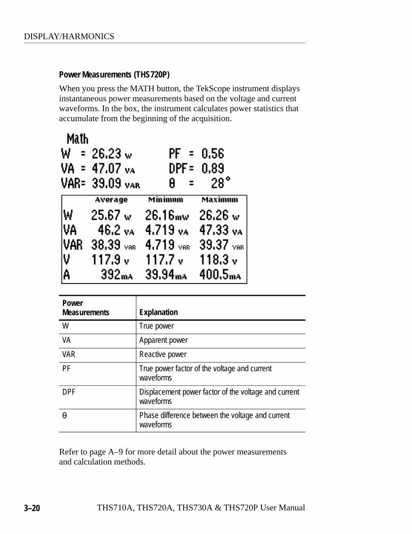
Power Measurements (THS720P)
When you press the MATH button, the TekScope instrument displaysinstantaneous power measurements based on the voltage and currentwaveforms. In the box, the instrument calculates power statistics thataccumulate from the beginning of the acquisition.
PowerMeasurements Explanation
W True power
VA Apparent power
VAR Reactive power
PF True power factor of the voltage and currentwaveforms
DPF Displacement power factor of the voltage and currentwaveforms
� Phase difference between the voltage and currentwaveforms
Refer to page A–9 for more detail about the power measurementsand calculation methods.

DISPLAY/HARMONICS
THS710A, THS720A, THS730A & THS720P User Manual 3–21
Display Menu in Meter Mode
METER DISPLAY Line Style ThinThick
—
Display Contrast — Set contrast
Graticule FullGridCross HairFrame
—
Key Points
Data Logger Line Style. For better visibility, choose Thick for athree-pixel-high data logger plot. The default (Thin) is one pixelhigh.
HARD COPY
3–22 THS710A, THS720A, THS730A & THS720P User Manual
HARD COPYYou can print a hard copy of the display if a printer is connected andproperly configured. Press the HARD COPY button to start printing.If you do not want menus to show, press CLEAR MENU before youpress HARD COPY. You cannot change instrument settings while thehard copy is printing.
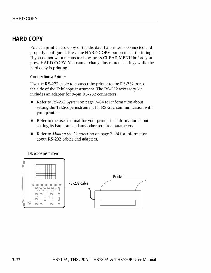
Connecting a Printer
Use the RS-232 cable to connect the printer to the RS-232 port onthe side of the TekScope instrument. The RS-232 accessory kitincludes an adapter for 9-pin RS-232 connectors.
� Refer to RS-232 System on page 3–64 for information aboutsetting the TekScope instrument for RS-232 communication withyour printer.
� Refer to the user manual for your printer for information aboutsetting its baud rate and any other required parameters.
� Refer to Making the Connection on page 3–24 for informationabout RS-232 cables and adapters.
Printer
TekScope instrument
RS-232 cable
HARD COPY
THS710A, THS720A, THS730A & THS720P User Manual 3–23
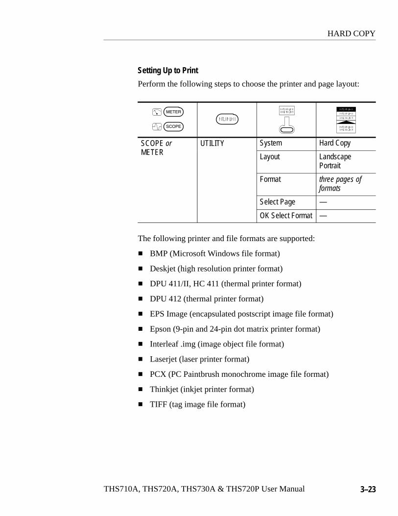
Setting Up to Print
Perform the following steps to choose the printer and page layout:
SCOPE orT R
UTILITY System Hard CopyMETER Layout Landscape
Portrait
Format three pages offormats
Select Page —
OK Select Format —
The following printer and file formats are supported:
� BMP (Microsoft Windows file format)
� Deskjet (high resolution printer format)
� DPU 411/II, HC 411 (thermal printer format)
� DPU 412 (thermal printer format)
� EPS Image (encapsulated postscript image file format)
� Epson (9-pin and 24-pin dot matrix printer format)
� Interleaf .img (image object file format)
� Laserjet (laser printer format)
� PCX (PC Paintbrush monochrome image file format)
� Thinkjet (inkjet printer format)
� TIFF (tag image file format)
HARD COPY
3–24 THS710A, THS720A, THS730A & THS720P User Manual
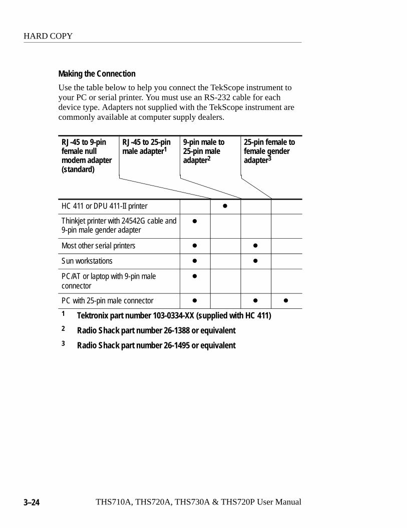
Making the Connection
Use the table below to help you connect the TekScope instrument toyour PC or serial printer. You must use an RS-232 cable for eachdevice type. Adapters not supplied with the TekScope instrument arecommonly available at computer supply dealers.
RJ-45 to 9-pinfemale nullmodem adapter(standard)
RJ-45 to 25-pinmale adapter1
9-pin male to25-pin maleadapter2
25-pin female tofemale genderadapter3
HC 411 or DPU 411-II printer �
Thinkjet printer with 24542G cable and9-pin male gender adapter
�
Most other serial printers � �
Sun workstations � �
PC/AT or laptop with 9-pin maleconnector
�
PC with 25-pin male connector � � �
1 Tektronix part number 103-0334-XX (supplied with HC 411)2 Radio Shack part number 26-1388 or equivalent3 Radio Shack part number 26-1495 or equivalent

HARD COPY
THS710A, THS720A, THS730A & THS720P User Manual 3–25
Troubleshooting RS-232 Problems
If the TekScope instrument and the personal computer or printerhave trouble communicating, use the following steps to correct theproblem:
� Verify that you are using the correct RS-232 cable and adapters.Determine whether your configuration requires a null-modemconnection (where transmit/receive and control lines areswitched) or a straight-through RS-232 connection.
� Verify that the RS-232 cable and adapters are firmly connected toboth the TekScope instrument and the correct port on yourpersonal computer or printer. Verify that your printer or theprogram on the personal computer is using the correct port. Tryyour program or printer again.
� Verify that the TekScope instrument settings match the settingsused by your printer or the program on your personal computer.Start by choosing Set RS-232 Parameters to Defaults (in theRS-232 System of the Utility menu). Then, change only thosemenu items that you know need to be changed, such as the baudrate. Try your printer or computer program again.
HOLD
3–26 THS710A, THS720A, THS730A & THS720P User Manual
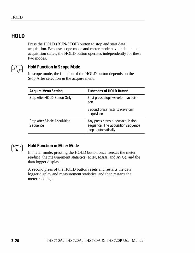
HOLDPress the HOLD (RUN/STOP) button to stop and start dataacquisition. Because scope mode and meter mode have independentacquisition states, the HOLD button operates independently for thesetwo modes.
Hold Function in Scope ModeIn scope mode, the function of the HOLD button depends on theStop After selection in the acquire menu.
Acquire Menu Setting Functions of HOLD Button
Stop After HOLD Button Only First press stops waveform acquisi-tion.
Second press restarts waveformacquisition.
Stop After Single AcquisitionSequence
Any press starts a new acquisitionsequence. The acquisition sequencestops automatically.
Hold Function in Meter ModeIn meter mode, pressing the HOLD button once freezes the meterreading, the measurement statistics (MIN, MAX, and AVG), and thedata logger display.
A second press of the HOLD button resets and restarts the datalogger display and measurement statistics, and then restarts themeter readings.

HORIZONTAL Controls
THS710A, THS720A, THS730A & THS720P User Manual 3–27
HORIZONTAL ControlsYou can use the horizontal controls to change the time base,horizontal position, and horizontal magnification of waveforms.
Horizontal Operations in Scope Mode
SCOPE HORIZON-TA NU
Time Base Main —TAL MENU Delayed Runs
After MainSet delay time
Trigger Position Set to 10%Set to 50%Set to 90%
—
% Pretrigger Set %
Display �T� atTrig Pt
OnOff
—
Set Delay WithCursor V Bars
—
HORIZONTAL Controls
3–28 THS710A, THS720A, THS730A & THS720P User Manual
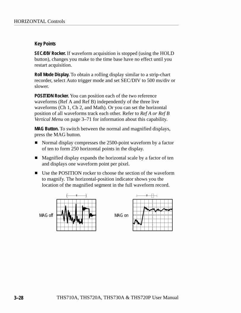
Key Points
SEC/DIV Rocker. If waveform acquisition is stopped (using the HOLDbutton), changes you make to the time base have no effect until yourestart acquisition.
Roll Mode Display. To obtain a rolling display similar to a strip-chartrecorder, select Auto trigger mode and set SEC/DIV to 500 ms/div orslower.
POSITION Rocker. You can position each of the two referencewaveforms (Ref A and Ref B) independently of the three livewaveforms (Ch 1, Ch 2, and Math). Or you can set the horizontalposition of all waveforms track each other. Refer to Ref A or Ref BVertical Menu on page 3–71 for information about this capability.
MAG Button. To switch between the normal and magnified displays,press the MAG button.
� Normal display compresses the 2500-point waveform by a factorof ten to form 250 horizontal points in the display.
� Magnified display expands the horizontal scale by a factor of tenand displays one waveform point per pixel.
� Use the POSITION rocker to choose the section of the waveformto magnify. The horizontal-position indicator shows you thelocation of the magnified segment in the full waveform record.
MAG off MAG on
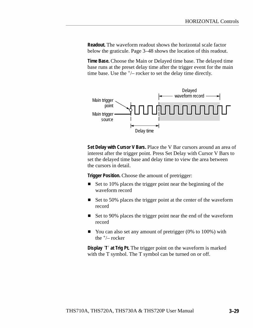
HORIZONTAL Controls
THS710A, THS720A, THS730A & THS720P User Manual 3–29
Readout. The waveform readout shows the horizontal scale factorbelow the graticule. Page 3–48 shows the location of this readout.
Time Base. Choose the Main or Delayed time base. The delayed timebase runs at the preset delay time after the trigger event for the maintime base. Use the +/– rocker to set the delay time directly.
Delay time
Main triggerpoint
Main triggersource
Delayedwaveform record
Set Delay with Cursor V Bars. Place the V Bar cursors around an area ofinterest after the trigger point. Press Set Delay with Cursor V Bars toset the delayed time base and delay time to view the area betweenthe cursors in detail.
Trigger Position. Choose the amount of pretrigger:
� Set to 10% places the trigger point near the beginning of thewaveform record
� Set to 50% places the trigger point at the center of the waveformrecord
� Set to 90% places the trigger point near the end of the waveformrecord
� You can also set any amount of pretrigger (0% to 100%) withthe +/– rocker
Display �T� at Trig Pt. The trigger point on the waveform is markedwith the T symbol. The T symbol can be turned on or off.
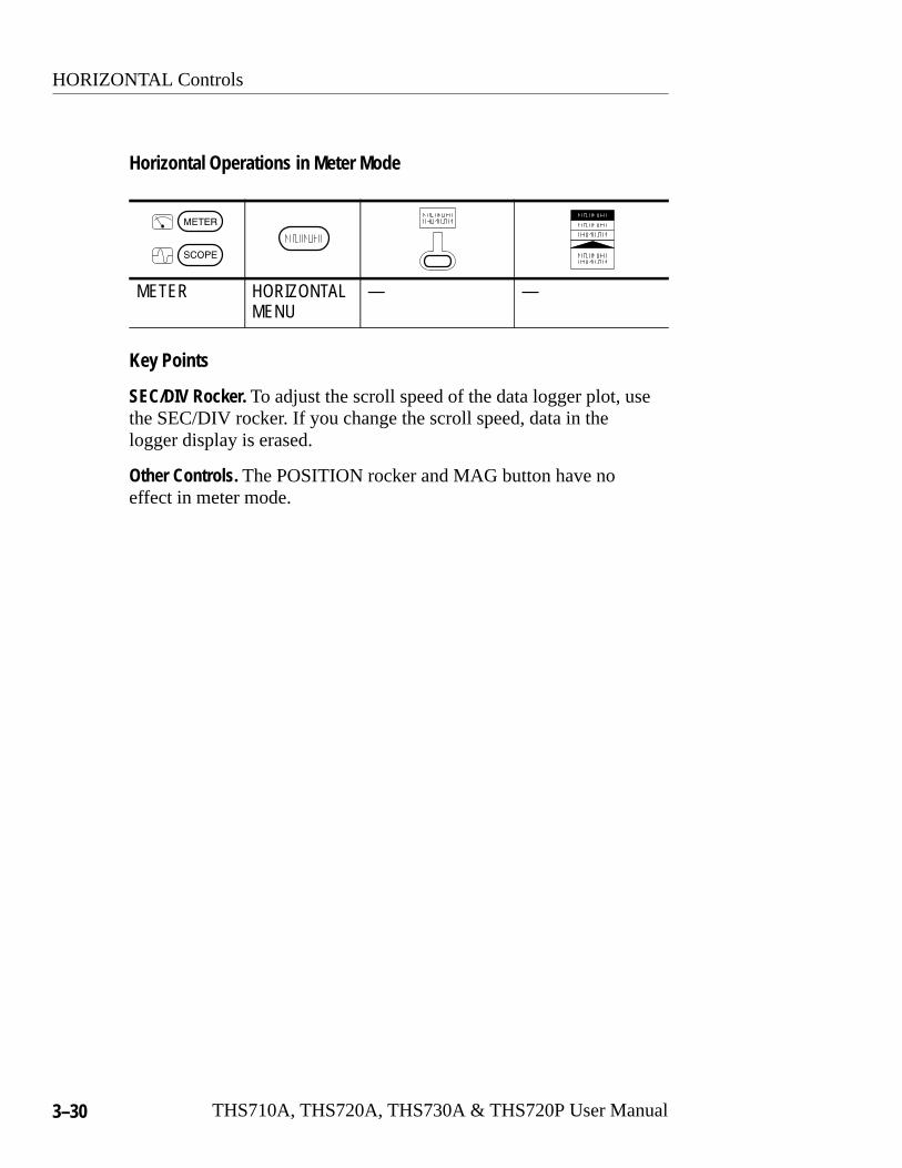
HORIZONTAL Controls
3–30 THS710A, THS720A, THS730A & THS720P User Manual
Horizontal Operations in Meter Mode
METER HORIZONTALMENU
— —
Key Points
SEC/DIV Rocker. To adjust the scroll speed of the data logger plot, usethe SEC/DIV rocker. If you change the scroll speed, data in thelogger display is erased.
Other Controls. The POSITION rocker and MAG button have noeffect in meter mode.

MEAS
THS710A, THS720A, THS730A & THS720P User Manual 3–31
MEASYou can use the MEAS button to access the automatic measurementcapability of the TekScope instrument. In scope mode, theinstrument measures the 2500-point, selected waveform. In metermode, the measurements take the form of statistics, which arecalculated from successive meter readings.
Measurements in Scope Mode
SCOPE MEAS SelectMeastmnt
six pages ofmeasurements
—
Select Page —
RemoveMeasrmnt
Measrmnt Choose measurement
All Measrmnts —
Gating & High-Low Setup
MeasurementGating
OffOn
High-LowMethod
HistogramMin/Max
OK SelectMeasrmnt
OK RemoveMeasrmnt
— —

MEAS
3–32 THS710A, THS720A, THS730A & THS720P User Manual
Key Points
Choosing Measurements. You can perform up to four automaticmeasurements on the selected waveform and display them alongthe right side of the graticule. The table beginning on page 3–35describes the scope-mode measurements in detail.
Power Measurements (THS720P). Refer to page 3–20 for informationabout power measurements.
MEAS
THS710A, THS720A, THS730A & THS720P User Manual 3–33
High-Low Setup. The TekScope instrument determines the 10%, 50%,or 90% levels of the selected waveform and then uses them tocalculate the measurements. You can choose the method used todetermine these levels:
� Histogram sets the values statistically; it finds the most commonvalue either above or below the midpoint (depending on whetherit is defining the high or low reference level). Since thisstatistical approach ignores short-term aberrations (overshoot,ringing, noise), histogram is the best method for measuringdigital waveforms and pulses.
� Min-max uses the highest and lowest values of the waveformrecord. This method is best for measuring waveforms that haveno large, flat portions at a common value, such as sine waves andtriangle waves.

MEAS
3–34 THS710A, THS720A, THS730A & THS720P User Manual
Measurement Gating. You can use the gating feature to limitmeasurements to the portion of the waveform that is between thecursors. When you turn gating on, the instrument displays verticalbar cursors. Use the +/– rocker and TOGGLE button to move thecursors to the area of interest.
In the example below, the cursors surround the second positive-goingpulse so the instrument can measure its width.
When gating is off, the instrument takes measurements over theentire waveform record.
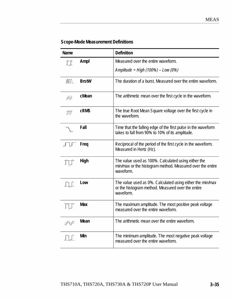
MEAS
THS710A, THS720A, THS730A & THS720P User Manual 3–35
Scope-Mode Measurement Definitions
Name Definition
Ampl Measured over the entire waveform.
Amplitude = High (100%) – Low (0%)
BrstW The duration of a burst. Measured over the entire waveform.
cMean The arithmetic mean over the first cycle in the waveform.
cRMS The true Root Mean Square voltage over the first cycle inthe waveform.
Fall Time that the falling edge of the first pulse in the waveformtakes to fall from 90% to 10% of its amplitude.
Freq Reciprocal of the period of the first cycle in the waveform.Measured in Hertz (Hz).
High The value used as 100%. Calculated using either themin/max or the histogram method. Measured over the entirewaveform.
Low The value used as 0%. Calculated using either the min/maxor the histogram method. Measured over the entirewaveform.
Max The maximum amplitude. The most positive peak voltagemeasured over the entire waveform.
Mean The arithmetic mean over the entire waveform.
Min The minimum amplitude. The most negative peak voltagemeasured over the entire waveform.

MEAS
3–36 THS710A, THS720A, THS730A & THS720P User Manual
Scope-Mode Measurement Definitions (Cont.)
Name Definition
–Duty Measurement of the first cycle in the waveform.
Negative Duty Cycle�Negative Width
Period� 100%
–Over Measured over the entire waveform.
Negative Overshoot� Low–MinAmplitude
� 100%
–Width Measurement of the first negative pulse in the waveform.The time between the 50% amplitude points.
Pk–Pk Measured over the entire waveform.
Amplitude = Max – Min
Period Time it takes for the first complete signal cycle to completein the waveform. Measured in seconds.
+Duty Measurement of the first cycle in the waveform.
Positive Duty Cycle� Positive WidthPeriod
� 100%
+Over Measured over the entire waveform.
Positive Overshoot�Max–HighAmplitude
� 100%
+Width Measurement of the first positive pulse in the waveform.The time between the 50% amplitude points.
Rise Time that the leading edge of the first pulse in the waveformtakes to rise from 10% to 90% of its amplitude.
RMS The true Root Mean Square voltage over the entirewaveform.

MEAS
THS710A, THS720A, THS730A & THS720P User Manual 3–37
Measurements in Meter Mode
METER MEAS Select Statisticfor DMM
MaxAvgMinRel �Max – Min
—
Select Page —
Removes
Statistic Choose statisticStatistic All Statistics —
Beep NewMax-Min
OnOff
OK SelectStatistic
OK RemoveStatistic
—
Key Points
Data Included in Statistics. The statistics are calculated over all meterreadings since the last reset. The statistics can represent data that isno longer displayed in the data logger plot.
Readout. The statistic readouts appear in the upper-right corner of thedisplay. See page 3–39 for the location.
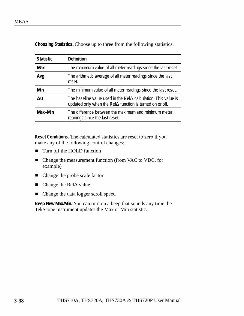
MEAS
3–38 THS710A, THS720A, THS730A & THS720P User Manual
Choosing Statistics. Choose up to three from the following statistics.
Statistic Definition
Max The maximum value of all meter readings since the last reset.
Avg The arithmetic average of all meter readings since the lastreset.
Min The minimum value of all meter readings since the last reset.
�� The baseline value used in the Rel� calculation. This value isupdated only when the Rel� function is turned on or off.
Max–Min The difference between the maximum and minimum meterreadings since the last reset.
Reset Conditions. The calculated statistics are reset to zero if youmake any of the following control changes:
� Turn off the HOLD function
� Change the measurement function (from VAC to VDC, forexample)
� Change the probe scale factor
� Change the Rel� value
� Change the data logger scroll speed
Beep New Max/Min. You can turn on a beep that sounds any time theTekScope instrument updates the Max or Min statistic.
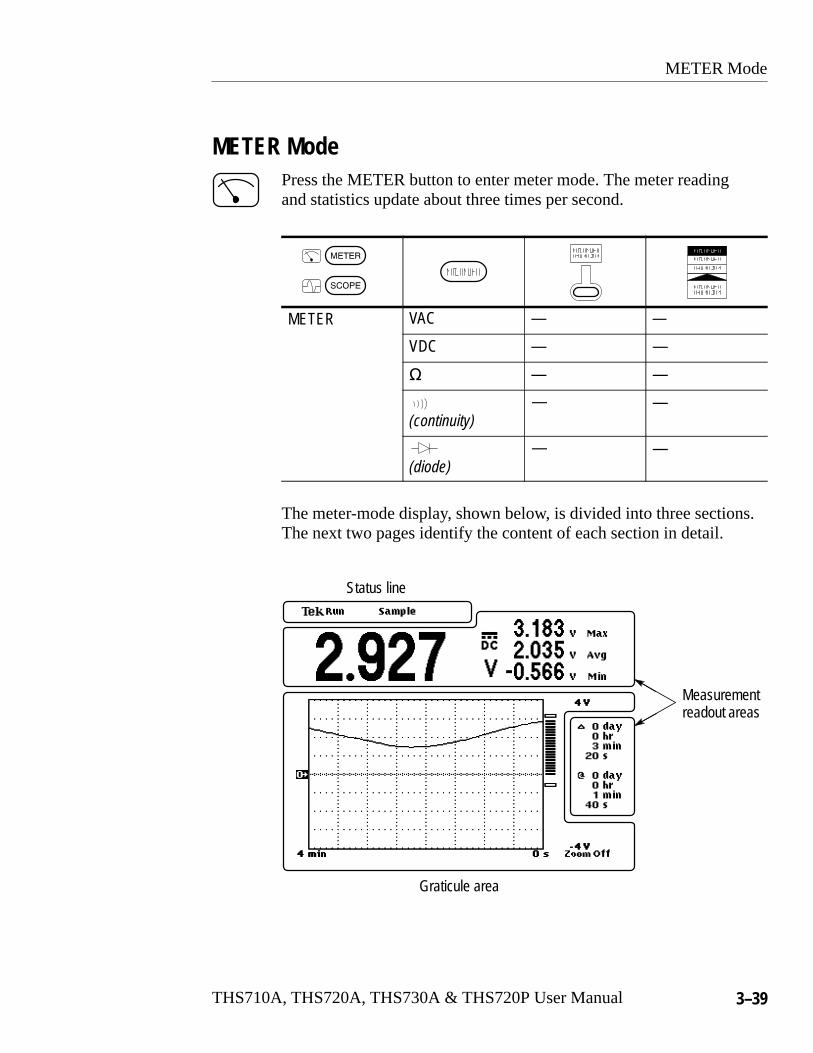
METER Mode
THS710A, THS720A, THS730A & THS720P User Manual 3–39
METER ModePress the METER button to enter meter mode. The meter readingand statistics update about three times per second.
METER VAC — —
VDC — —
� — —
(continuity)— —
(diode)— —
The meter-mode display, shown below, is divided into three sections.The next two pages identify the content of each section in detail.
Graticule area
Measurementreadout areas
Status line

METER Mode
3–40 THS710A, THS720A, THS730A & THS720P User Manual
Status Line
The status line across the top of the display contains acquisitioninformation. The overrange indicator warns when an overvoltage isapplied to the input.
Acquisition readout Overrange indicator
The table below shows examples of the acquisition readout.
Acquisition Readout Explanation
Acquisition running with autorange function on (AUTORANG r ff R r q s s s ed dRANGE) or off (Run), or acquisition is stopped (Hold)
Saved data is recalled for display (from location 7)while acquisition runs in the background
Acquisition mode for data logger

METER Mode
THS710A, THS720A, THS730A & THS720P User Manual 3–41
Graticule Area
The graticule area contains the data logger plot, the bar graph, theirscale markers, and the zoom factor readout.
Referencelevel
Data logger plotUpper verticalrange marker
Bar graph
Horizontal scale markers
Lower verticalrange marker
Zoom factor
Measurement Readout Area
The area above and to the right of the graticule contains the currentmeter reading, statistic readouts, and cursor readouts.
Statisticreadouts
Cursorreadouts
Current meter reading
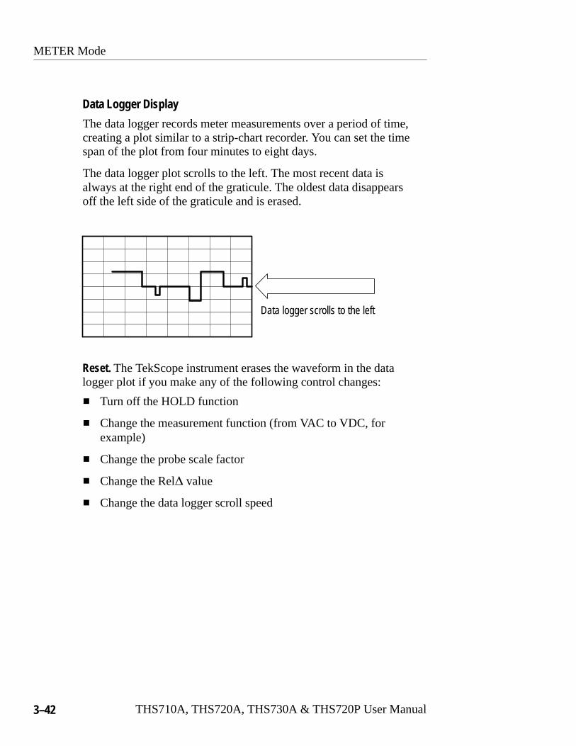
METER Mode
3–42 THS710A, THS720A, THS730A & THS720P User Manual
Data Logger Display
The data logger records meter measurements over a period of time,creating a plot similar to a strip-chart recorder. You can set the timespan of the plot from four minutes to eight days.
The data logger plot scrolls to the left. The most recent data isalways at the right end of the graticule. The oldest data disappearsoff the left side of the graticule and is erased.
Data logger scrolls to the left
Reset. The TekScope instrument erases the waveform in the datalogger plot if you make any of the following control changes:
� Turn off the HOLD function
� Change the measurement function (from VAC to VDC, forexample)
� Change the probe scale factor
� Change the Rel� value
� Change the data logger scroll speed

METER Mode
THS710A, THS720A, THS730A & THS720P User Manual 3–43
Zero Level. If you select the VDC meter function, the zero level islocated at the horizontal centerline of the graticule; for all othermeter functions, the zero level is the bottom of the graticule. Use thevertical POSITION rocker to move the zero level.
Reference Level. If the Rel� function is turned on, the Rel� baselinevalue is marked along the left side of the graticule.
VOLTS/DIV Rocker. Use the VOLTS/DIV rocker to set the meter rangeand control the vertical scale of the data logger plot. If you changethe vertical scale while the data logger is running, you will cause avertical discontinuity; old data is not rescaled to match the currentsetting. However, if you change the vertical scale while the HOLDfunction is active, the entire waveform is scaled to match the currentsetting.
SEC/DIV Rocker. Use the SEC/DIV rocker to control the scroll speedof the data logger plot. When you change the scroll speed, existingdata in the data logger plot is erased.
Zoom. You can vertically enlarge the data logger plot around thecenter of the screen for the VDC function, and around the bottom ofthe screen for other functions. The zoom feature allows you to seethe full vertical resolution of the meter.
Use the vertical POSITION rocker to move the plot before choosingZoom. Then, choose Zoom in the Vertical Menu to set the zoomfactor (refer to page 3–72). If you change the range or function, theplot position and size are reset to their default values.
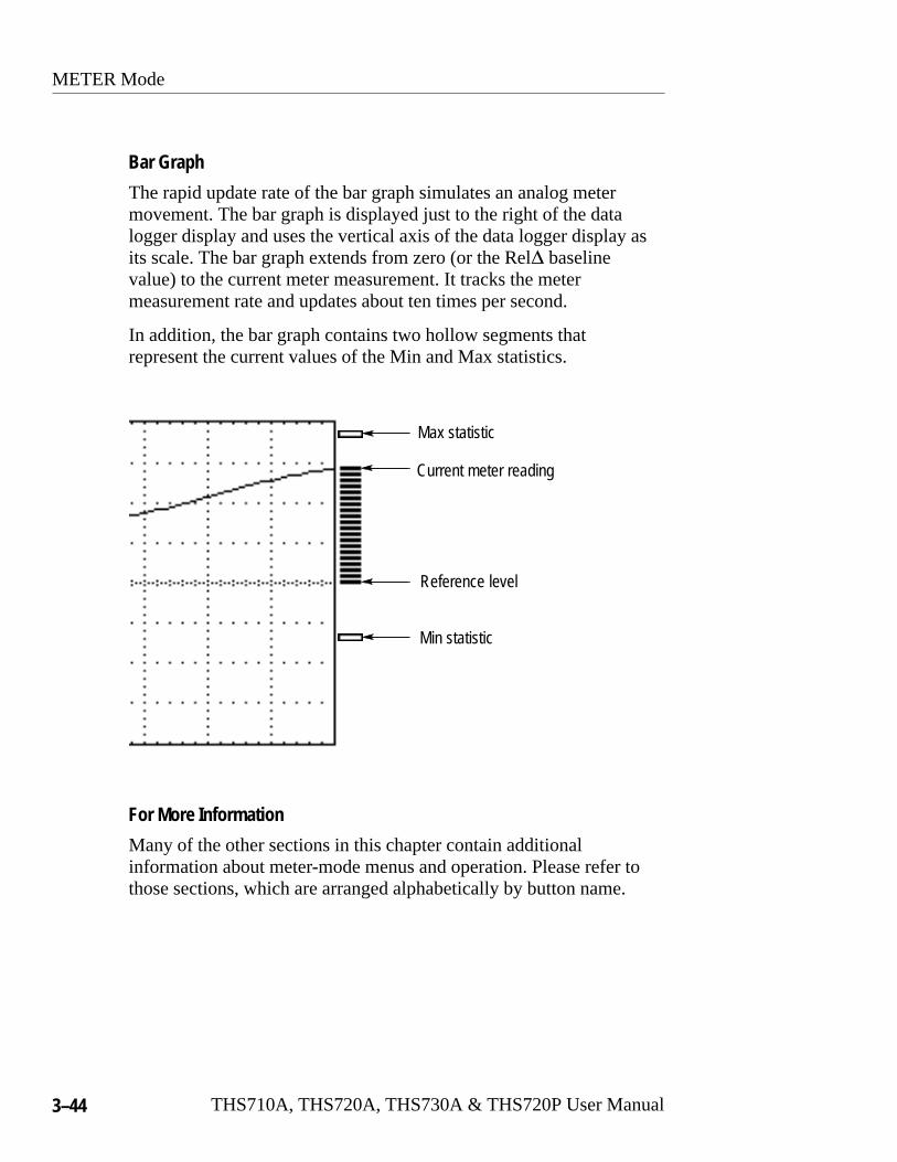
METER Mode
3–44 THS710A, THS720A, THS730A & THS720P User Manual
Bar Graph
The rapid update rate of the bar graph simulates an analog metermovement. The bar graph is displayed just to the right of the datalogger display and uses the vertical axis of the data logger display asits scale. The bar graph extends from zero (or the Rel� baselinevalue) to the current meter measurement. It tracks the metermeasurement rate and updates about ten times per second.
In addition, the bar graph contains two hollow segments thatrepresent the current values of the Min and Max statistics.
Current meter reading
Max statistic
Min statistic
Reference level
For More Information
Many of the other sections in this chapter contain additionalinformation about meter-mode menus and operation. Please refer tothose sections, which are arranged alphabetically by button name.

SAVE/RECALL
THS710A, THS720A, THS730A & THS720P User Manual 3–45
SAVE/RECALLPress the SAVE/RECALL button to save or recall any of thefollowing:
� Setups
� Oscillscope waveforms
� DMM Data
Save/Recall Menu in Scope Mode
SCOPE SAVE/RECALL
Save CurrentSetup
To Setup Choose setuplocation
Recall SavedSetup
Recall FactorySetup
—
Recall Setup Choose setuplocation
Save selectedwfm
To Waveform Choose wave-form location
Recall SavedWaveform
Load REFAFrom Wfrm
Load REFBFrom Wfrm
OK Save Setup
OK RecallSetup
OK RecallFactory
OK SaveWaveform
OK RecallWaveform
— —

SAVE/RECALL
3–46 THS710A, THS720A, THS730A & THS720P User Manual
Key Points
Saving and Recalling Setups. Whether you save a setup in scope modeor meter mode, the TekScope instrument stores its complete setup innonvolatile memory. When you recall the setup, you will be in themode from which the setup was saved.
Recalling the Factory Setup. You can recall the Factory Setup toinitialize the TekScope instrument to a known setup. Appendix Bdescribes the Factory Setup in detail.
Saving a Waveform. Push the CH 1, CH 2, or MATH button to choosethe waveform to save. Waveform position and scale factors are savedwith each waveform.
Recalling a Waveform. Recall a saved waveform into either Ref A orRef B for display. When you recall a saved waveform, the recalledwaveform overwrites the previous Ref A or Ref B waveform.
Saving and Displaying a Waveform in One Step. Using a vertical menu,you can save a waveform and keep it for display at the same time.Refer to Ref A or Ref B Vertical Menu on page 3–71 for informationabout this capability.
Saving Harmonics Data (THS720P). If you save the channel 1 orchannel 2 waveform while the harmonics display is on, the harmonicmeasurements and bargraphs are also saved. When you recall thewaveform, turn the harmonics display on to see the harmonicsmeasurements and bargraphs.
Saving Power Measurement Data (THS720P). If you save the MATHwaveform while the harmonics display is on, the power measure-ments are also saved. When you recall the waveform, turn theharmonics display on to see the power measurements.

SAVE/RECALL
THS710A, THS720A, THS730A & THS720P User Manual 3–47
Save/Recall Menu in Meter Mode
METER SAVE/RECALL
Save CurrentSetup
To Setup Choose setuplocation
Recall SavedSetup
Recall FactorySetup
—
Recall Setup Choose setuplocation
Save DMMData
To Data Choose DMMdata location
Recall DMMData
Recall Data
Clear DataFrom Screen
OK Save Setup
OK RecallSetup
OK RecallFactory
OK Save Data
OK Recall Data
OK Clear Data
— —
Key Points
Saving and Recalling Setups. Whether you save a setup in scope modeor meter mode, the TekScope instrument stores its complete setup innonvolatile memory.
Saving DMM Data. Saving DMM data saves the meter mode, meterrange, current DMM reading, statistics, and data logger plot.

SCOPE Mode
3–48 THS710A, THS720A, THS730A & THS720P User Manual
SCOPE ModePress the SCOPE button to enter scope mode. If already in scopemode, pressing this button has no effect.
The scope-mode display, shown below, is divided into four sections.The next five pages identify the content of each section in detail.
Status line
Waveform readout lines
Measurementreadout area
Graticulearea
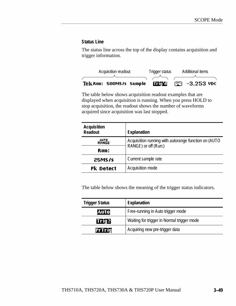
SCOPE Mode
THS710A, THS720A, THS730A & THS720P User Manual 3–49
Status Line
The status line across the top of the display contains acquisition andtrigger information.
Trigger statusAcquisition readout Additional items
The table below shows acquisition readout examples that aredisplayed when acquisition is running. When you press HOLD tostop acquisition, the readout shows the number of waveformsacquired since acquisition was last stopped.
Acquisition Readout Explanation
Acquisition running with autorange function on (AUTORANG r ff RRANGE) or off (Run:)
Current sample rate
Acquisition mode
The table below shows the meaning of the trigger status indicators.
Trigger Status Explanation
Free-running in Auto trigger mode
Waiting for trigger in Normal trigger mode
Acquiring new pre-trigger data
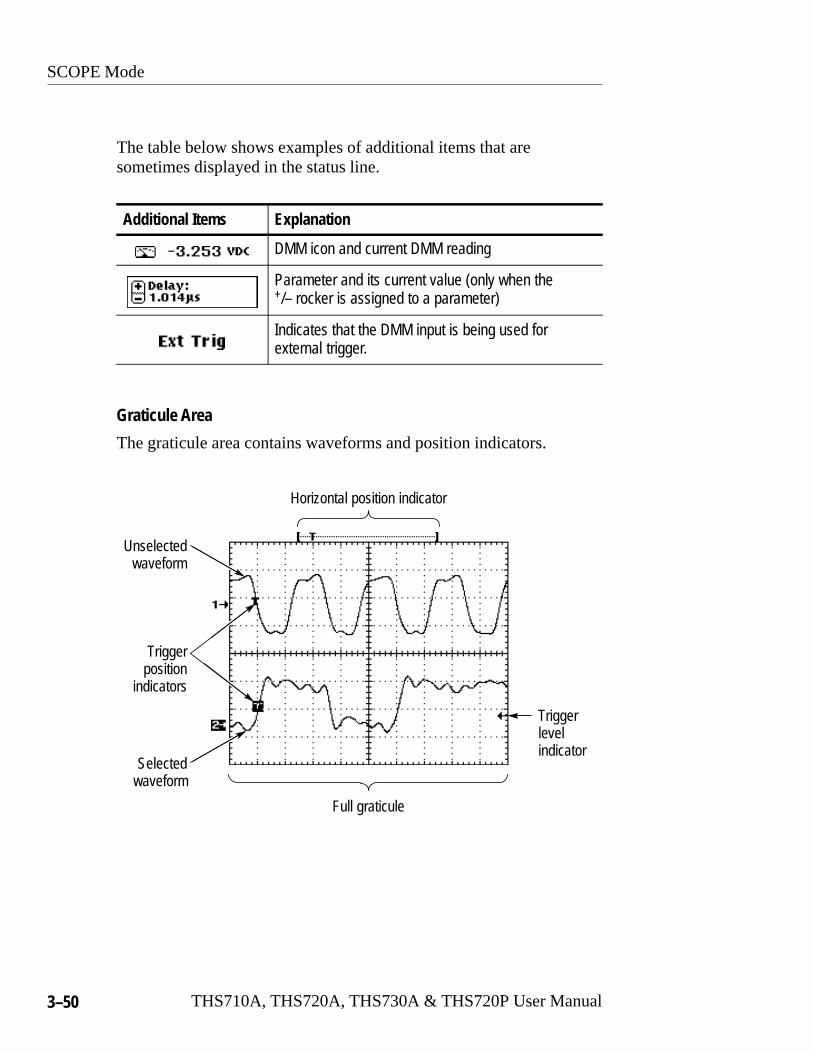
SCOPE Mode
3–50 THS710A, THS720A, THS730A & THS720P User Manual
The table below shows examples of additional items that aresometimes displayed in the status line.
Additional Items Explanation
DMM icon and current DMM reading
Parameter and its current value (only when the+/– rocker is assigned to a parameter)
Indicates that the DMM input is being used forexternal trigger.
Graticule Area
The graticule area contains waveforms and position indicators.
Full graticule
Horizontal position indicator
Selectedwaveform
Triggerlevelindicator
Unselectedwaveform
Triggerposition
indicators
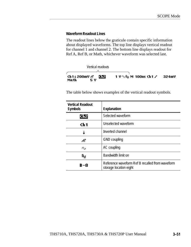
SCOPE Mode
THS710A, THS720A, THS730A & THS720P User Manual 3–51
Waveform Readout Lines
The readout lines below the graticule contain specific informationabout displayed waveforms. The top line displays vertical readoutfor channel 1 and channel 2. The bottom line displays readout forRef A, Ref B, or Math, whichever waveform was selected last.
Vertical readouts
The table below shows examples of the vertical readout symbols.
Vertical ReadoutSymbols Explanation
Selected waveform
Unselected waveform
Inverted channel
GND coupling
AC coupling
Bandwidth limit on
Reference waveform Ref B recalled from waveformstorage location eight

SCOPE Mode
3–52 THS710A, THS720A, THS730A & THS720P User Manual
The waveform readout lines also show time base and triggerinformation.
Triggerinformation
Reference waveformtime base
Main ordelayed
time base
The table below shows examples of time base information.
Time Base Information Explanation
Main time base
Delayed time base
The table below shows examples of the trigger information.
Trigger Information Explanation
Trigger source
Edge trigger slope
Trigger level
Pulse trigger polarity
Pulse trigger condition
Pulse trigger width
Video trigger condition
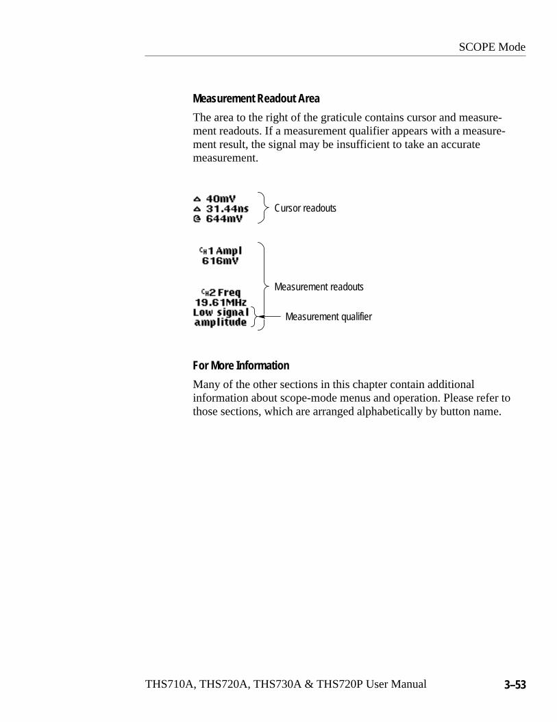
SCOPE Mode
THS710A, THS720A, THS730A & THS720P User Manual 3–53
Measurement Readout Area
The area to the right of the graticule contains cursor and measure-ment readouts. If a measurement qualifier appears with a measure-ment result, the signal may be insufficient to take an accuratemeasurement.
Cursor readouts
Measurement readouts
Measurement qualifier
For More Information
Many of the other sections in this chapter contain additionalinformation about scope-mode menus and operation. Please refer tothose sections, which are arranged alphabetically by button name.
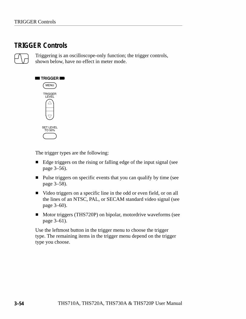
TRIGGER Controls
3–54 THS710A, THS720A, THS730A & THS720P User Manual
TRIGGER ControlsTriggering is an oscilloscope-only function; the trigger controls,shown below, have no effect in meter mode.
The trigger types are the following:
� Edge triggers on the rising or falling edge of the input signal (seepage 3–56).
� Pulse triggers on specific events that you can qualify by time (seepage 3–58).
� Video triggers on a specific line in the odd or even field, or on allthe lines of an NTSC, PAL, or SECAM standard video signal (seepage 3–60).
� Motor triggers (THS720P) on bipolar, motordrive waveforms (seepage 3–61).
Use the leftmost button in the trigger menu to choose the triggertype. The remaining items in the trigger menu depend on the triggertype you choose.
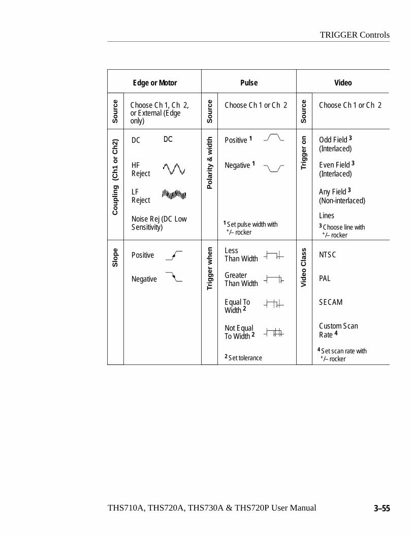
TRIGGER Controls
THS710A, THS720A, THS730A & THS720P User Manual 3–55
Edge or Motor
Choose Ch 1, Ch 2,or External (Edgeonly)
Positive
Negative
DC
HFReject
LFReject
Noise Rej (DC LowSensitivity)
Slo
peS
ourc
eC
oupl
ing
Pulse Video
Pol
arity
& w
idth
Sou
rce
Trig
ger
whe
n LessThan Width
GreaterThan Width
2 Set tolerance
Sou
rce
NTSC
Odd Field 3(Interlaced)
Even Field 3(Interlaced)
Any Field 3(Non-interlaced)
Vid
eo C
lass
Choose Ch 1 or Ch 2 Choose Ch 1 or Ch 2
Positive 1
Negative 1
1 Set pulse width with +/– rocker
Equal ToWidth 2
Not EqualTo Width 2
Trig
ger
on
PAL
SECAM
Custom ScanRate 4
Lines
(Ch1
or
Ch2
)
3 Choose line with +/– rocker
4 Set scan rate with +/– rocker

TRIGGER Controls
3–56 THS710A, THS720A, THS730A & THS720P User Manual
Edge Trigger
Use Edge triggering to trigger on the rising or falling edge of theinput signal at the trigger threshold.
SCOPE TRIGGERNU
Trigger Type Edge —MENU Trigger Source Ch1
Ch2Ext. [DMM]
Trigger Coupling (Ch 1 or Ch 2source only)
DCHF Reject LF RejectNoise Reject
Trigger Slope / (rising edge)\ (falling edge)
Mode & Holdoff AutoNormal
Set holdoff
Key Points
Normal and Auto Mode. Use Normal trigger mode when you want theoscilloscope to trigger only on a valid trigger. Use Auto trigger modewhen you want the acquisition to free-run in the absence of a validtrigger event. Also, choose Auto when you want an untriggered,rolling waveform at 500 ms/div or slower time base settings.
External Trigger. Use external trigger to trigger on a signal connectedto the DMM inputs. External trigger coupling is always DC. You canchoose either a 0.2 V or a 2 V trigger level.
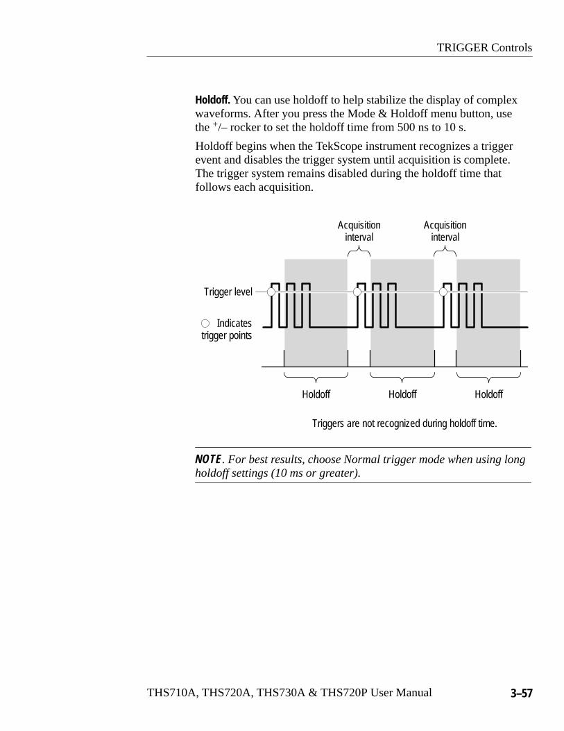
TRIGGER Controls
THS710A, THS720A, THS730A & THS720P User Manual 3–57
Holdoff. You can use holdoff to help stabilize the display of complexwaveforms. After you press the Mode & Holdoff menu button, usethe +/– rocker to set the holdoff time from 500 ns to 10 s.
Holdoff begins when the TekScope instrument recognizes a triggerevent and disables the trigger system until acquisition is complete.The trigger system remains disabled during the holdoff time thatfollows each acquisition.
Holdoff Holdoff
Indicatestrigger points
Trigger level
Holdoff
Acquisitioninterval
Acquisitioninterval
Triggers are not recognized during holdoff time.
NOTE. For best results, choose Normal trigger mode when using longholdoff settings (10 ms or greater).

TRIGGER Controls
3–58 THS710A, THS720A, THS730A & THS720P User Manual
Pulse Trigger
Use Pulse triggering to isolate and display specific events that youcan qualify by time.
SCOPE TRIGGERNU
Trigger Type Pulse —MENU Trigger Source Ch1
Ch2
Polarity &Width
PositiveNegative
Set width
Trigger When Less ThanWidth
Greater ThanWidth
—
Equal To Width
Not Equal ToWidth
Set ±%
Mode & Holdoff AutoNormal
—
Key Points
Trigger Conditions. You can trigger on the following conditions:
� Less Than Width triggers on a pulse width that is less than thetime threshold.
� Greater Than Width triggers on a pulse width that is greater thanthe time threshold.
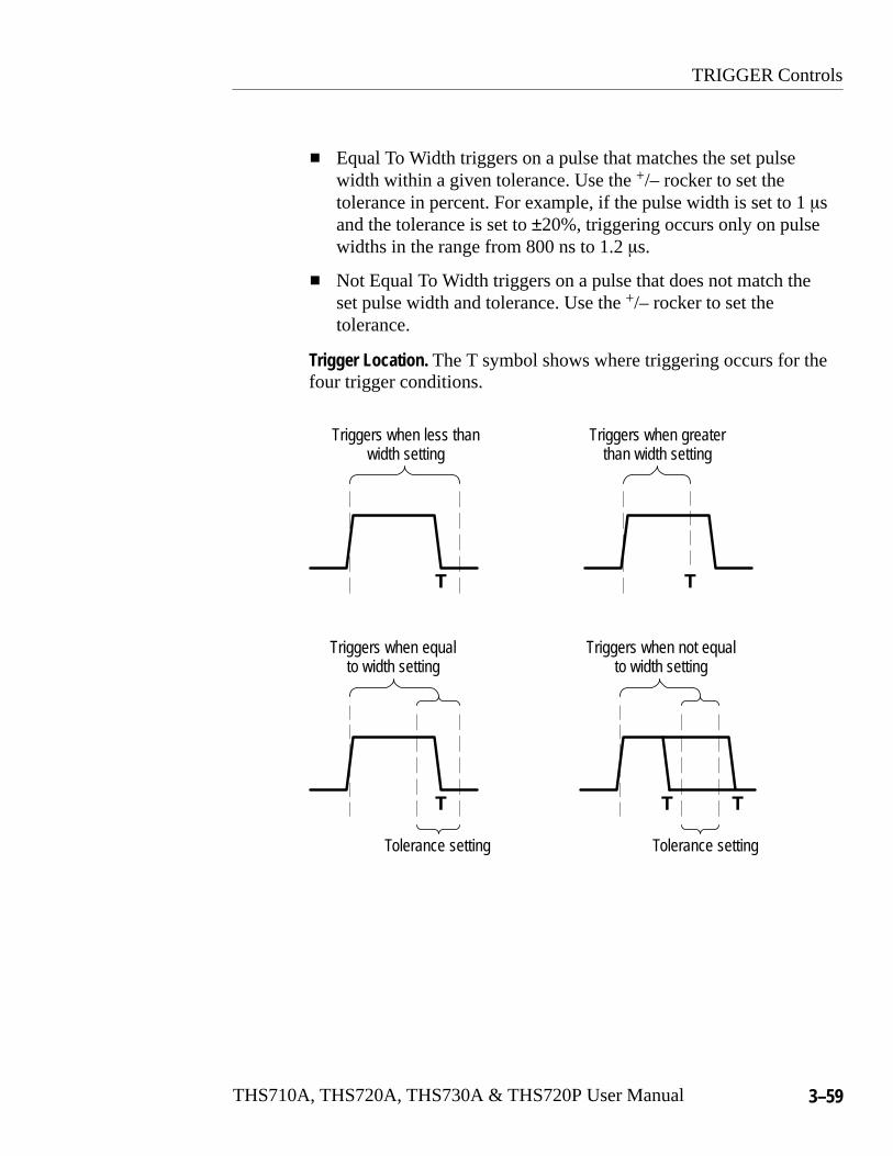
TRIGGER Controls
THS710A, THS720A, THS730A & THS720P User Manual 3–59
� Equal To Width triggers on a pulse that matches the set pulsewidth within a given tolerance. Use the +/– rocker to set thetolerance in percent. For example, if the pulse width is set to 1 �sand the tolerance is set to ±20%, triggering occurs only on pulsewidths in the range from 800 ns to 1.2 �s.
� Not Equal To Width triggers on a pulse that does not match theset pulse width and tolerance. Use the +/– rocker to set thetolerance.
Trigger Location. The T symbol shows where triggering occurs for thefour trigger conditions.
Tolerance settingTolerance setting
Triggers when less thanwidth setting
Triggers when greaterthan width setting
Triggers when not equalto width setting
Triggers when equalto width setting
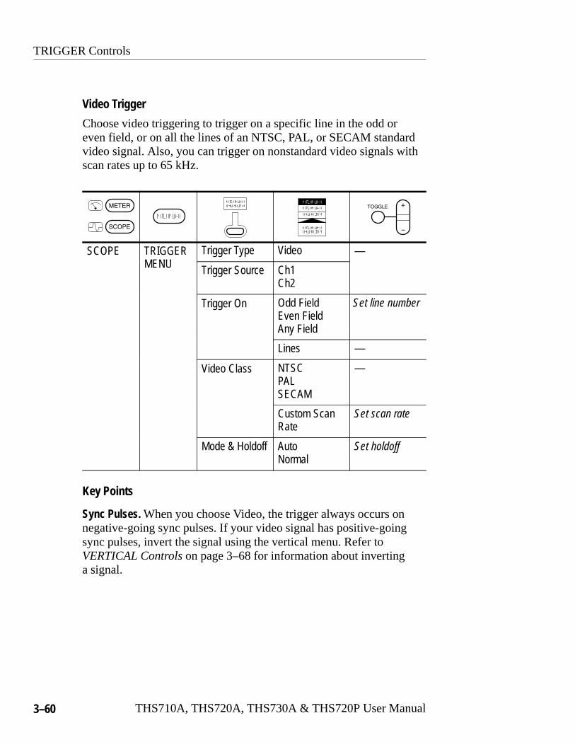
TRIGGER Controls
3–60 THS710A, THS720A, THS730A & THS720P User Manual
Video Trigger
Choose video triggering to trigger on a specific line in the odd oreven field, or on all the lines of an NTSC, PAL, or SECAM standardvideo signal. Also, you can trigger on nonstandard video signals withscan rates up to 65 kHz.
SCOPE TRIGGERNU
Trigger Type Video —MENU Trigger Source Ch1
Ch2
Trigger On Odd FieldEven FieldAny Field
Set line number
Lines —
Video Class NTSCPALSECAM
—
Custom ScanRate
Set scan rate
Mode & Holdoff AutoNormal
Set holdoff
Key Points
Sync Pulses. When you choose Video, the trigger always occurs onnegative-going sync pulses. If your video signal has positive-goingsync pulses, invert the signal using the vertical menu. Refer toVERTICAL Controls on page 3–68 for information about invertinga signal.

TRIGGER Controls
THS710A, THS720A, THS730A & THS720P User Manual 3–61
Motor Trigger (THS720P)
Choose motor triggering to trigger on the rising or falling edge of abipolar, motor drive waveform.
SCOPE TRIGGERNU
Trigger Type Motor —MENU Trigger Source Ch1
Ch2
Trigger Coupling
DCAC
Trigger Slope / (rising edge)\ (falling edge)
Mode & Holdoff AutoNormal
Set holdoff
Key Points
Trigger Level. You can set the trigger level from 0.1 to 5 divisions forpositive slope, and from –0.1 to –5 divisions for negative slope. Ifyou change the slope, the trigger level automatically changes sign.
UTILITY
3–62 THS710A, THS720A, THS730A & THS720P User Manual
UTILITYThe following are examples of what you can do with each of the sixbranches in the Utility menu:
� Use Config to display the firmware version.
� Use Hard Copy to set up hard copy parameters. Refer to HARDCOPY on page 3–22 for information about setting up and printinga hard copy.
� Use RS-232 to set up for remote communication.
� Use Misc to set the standby or backlight timeout.
� Use Cal to compensate the signal path.
� Use Diag to run internal diagnostic routines.
Press the UTILITY button to display the utility menu. You canaccess the same utility menu from scope mode or meter mode. Then,use the left-most button in the utility menu to choose the branch. Theremaining items in the utility menu may change depending on thebranch you choose.

UTILITY
THS710A, THS720A, THS730A & THS720P User Manual 3–63
Config System
SCOPE orT R
UTILITY System ConfigMETER Tek Secure Erase
Memory—
Version
OK Erase Setup/Data
Key Points
Tek Secure. If you have acquired confidential data, you may want toexecute Tek Secure before you return the TekScope instrument togeneral use. Executing Tek Secure accomplishes the following tasks:
� Replaces all waveforms (oscilloscope and data logger) in allreference memories with zero sample values
� Replaces the current front-panel setup and all stored setups withthe factory setup
� Calculates the checksums of all waveform memory and setupmemory locations to verify successful completion of waveformand setup erasure
� Displays a confirmation or warning message if the checksumcalculation is successful or unsuccessful
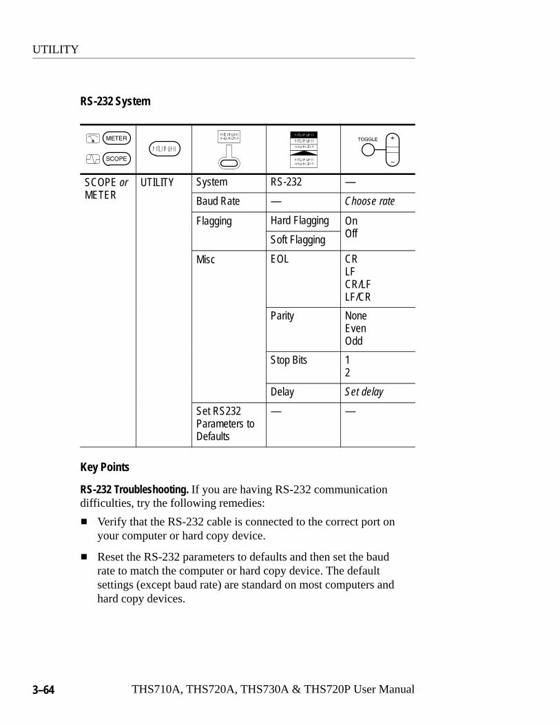
UTILITY
3–64 THS710A, THS720A, THS730A & THS720P User Manual
RS-232 System
SCOPE orT R
UTILITY System RS-232 —METER Baud Rate — Choose rate
Flagging Hard Flagging OnOffSoft Flagging Off
Misc EOL CRLFCR/LFLF/CR
Parity NoneEvenOdd
Stop Bits 12
Delay Set delay
Set RS232Parameters toDefaults
— —
Key Points
RS-232 Troubleshooting. If you are having RS-232 communicationdifficulties, try the following remedies:
� Verify that the RS-232 cable is connected to the correct port onyour computer or hard copy device.
� Reset the RS-232 parameters to defaults and then set the baudrate to match the computer or hard copy device. The defaultsettings (except baud rate) are standard on most computers andhard copy devices.
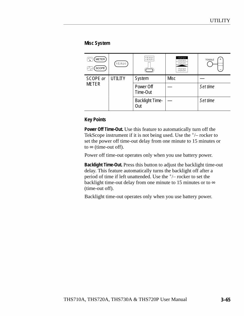
UTILITY
THS710A, THS720A, THS730A & THS720P User Manual 3–65
Misc System
SCOPE orT R
UTILITY System Misc —METER Power Off
Time-Out— Set time
Backlight Time-Out
— Set time
Key Points
Power Off Time-Out. Use this feature to automatically turn off theTekScope instrument if it is not being used. Use the +/– rocker toset the power off time-out delay from one minute to 15 minutes orto ∞ (time-out off).
Power off time-out operates only when you use battery power.
Backlight Time-Out. Press this button to adjust the backlight time-outdelay. This feature automatically turns the backlight off after aperiod of time if left unattended. Use the +/– rocker to set thebacklight time-out delay from one minute to 15 minutes or to ∞(time-out off).
Backlight time-out operates only when you use battery power.

UTILITY
3–66 THS710A, THS720A, THS730A & THS720P User Manual
Cal System
SCOPE orT R
UTILITY System CalMETER Signal Path —
Factory Scope
Factory DMM
OK CompensateSignal Path
OK Factory CalScope
OK Factory CalDMM
Key Points
Signal Path Compensation. Signal path compensation optimizes theoscilloscope accuracy for the current ambient temperature. Formaximum accuracy, recompensate the signal path if the ambienttemperature changes by 5° C or more.
To compensate the signal path, disconnect any probes or cables fromthe channel 1 and channel 2 input BNC connectors. Then, press theSignal Path and OK Compensate Signal Path buttons to confirmthat you are ready to proceed. This procedure takes about one minuteto complete.
Factory Scope and Factory DMM. Service personnel use these functionsto calibrate the oscillscope and DMM internal voltage references.Refer to your Tektronix field office or representative for assistancewith these processes.

UTILITY
THS710A, THS720A, THS730A & THS720P User Manual 3–67
Diag System
SCOPE orT R
UTILITY System DiagMETER Execute —
Loop OnceAlwaysUntil Fail
Error Log —
OK Run Test
OK Display Log
Key Points
Starting Diagnostics. To execute the built-in diagnostic routines,disconnect all cables, probes, or leads from the oscilloscope andDMM inputs, and then press the OK Run Test button.
Stopping Diagnostics. Choose how you want the diagnostic routines toexecute:
� Loop Once runs all diagnostic routines one time and then stops.
� Loop Always runs the diagnostic routines continuously. PressHOLD and then CLEAR MENU to resume normal operation.
� Loop Until Fail runs the diagnostic routines until the TekScopeinstrument fails a test or until you cycle the power.
Error Log. The error log contains summary data gathered over the lifeof the TekScope instrument and descriptions of the last 100 errorsencountered. The last error in the list is the most recent. Press the+/– rocker to display subsequent pages of the error log.

VERTICAL Controls
3–68 THS710A, THS720A, THS730A & THS720P User Manual
VERTICAL ControlsYou can use the vertical controls to display waveforms, adjustvertical scale and position, and set input parameters. In the THS720PTekScope instrument, the vertical controls are also used to displaywaveform harmonics. Refer to page 3–16 for a description ofharmonics.
Vertical Operations in Scope Mode
All vertical operations affect the selected waveform. Press the CH 1,CH 2, MATH, REF A, or REF B button to select that waveform.
In harmonics mode (THS720P), the CH 1, CH 2, and MATH buttonsdisplay harmonics of voltage, current, and power waveforms.
To remove a waveform from the display, select the waveform andthen press the WAVEFORM OFF button.
Press the MENU button to display the vertical menu. The contents ofthe vertical menu depend on which waveform is selected.

VERTICAL Controls
THS710A, THS720A, THS730A & THS720P User Manual 3–69
Channel 1 or Channel 2 Vertical Menu
The vertical menu contains the following items when channel 1 orchannel 2 is the selected waveform.
SCOPE VERTICALMENU
Coupling DCACGND
—
Invert Invert OffInvert On
Bandwidth Full Bandwidth20 MHz
Position —
Probe Type Current Probe Set conversionfactor
Voltage Probe Set probeattenuation
Key Points
GND Coupling. Use GND coupling to display a zero-volt waveform.When you use GND coupling, the input BNC connector isdisconnected from internal circuits. Internally, the channel input andits reference are connected to create a zero-volt reference level.
VOLTS/DIV Rocker. Use the VOLTS/DIV rocker to change the verticalsensitivity when acquisition is running. When acquisition is stopped,the rocker scales the waveform vertically.
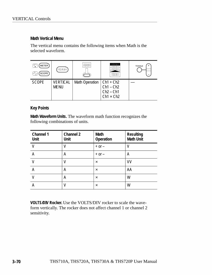
VERTICAL Controls
3–70 THS710A, THS720A, THS730A & THS720P User Manual
Math Vertical Menu
The vertical menu contains the following items when Math is theselected waveform.
SCOPE VERTICALMENU
Math Operation Ch1 + Ch2Ch1 – Ch2Ch2 – Ch1Ch1 × Ch2
—
Key Points
Math Waveform Units. The waveform math function recognizes thefollowing combinations of units.
Channel 1 Unit
Channel 2 Unit
MathOperation
Resulting Math Unit
V V + or – V
A A + or – A
V V × VV
A A × AA
V A × W
A V × W
VOLTS/DIV Rocker. Use the VOLTS/DIV rocker to scale the wave-form vertically. The rocker does not affect channel 1 or channel 2sensitivity.
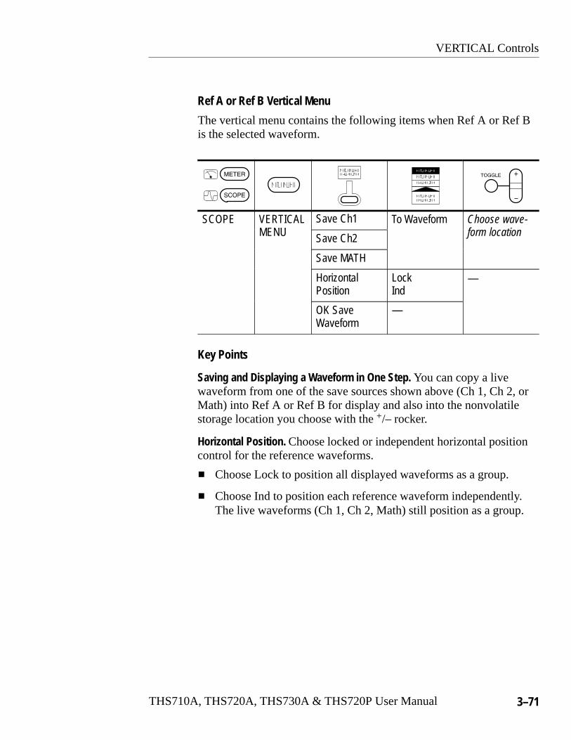
VERTICAL Controls
THS710A, THS720A, THS730A & THS720P User Manual 3–71
Ref A or Ref B Vertical Menu
The vertical menu contains the following items when Ref A or Ref Bis the selected waveform.
SCOPE VERTICALNU
Save Ch1 To Waveform Choose wave-fMENU Save Ch2 form location
Save MATH
HorizontalPosition
LockInd
—
OK SaveWaveform
—
Key Points
Saving and Displaying a Waveform in One Step. You can copy a livewaveform from one of the save sources shown above (Ch 1, Ch 2, orMath) into Ref A or Ref B for display and also into the nonvolatilestorage location you choose with the +/– rocker.
Horizontal Position. Choose locked or independent horizontal positioncontrol for the reference waveforms.
� Choose Lock to position all displayed waveforms as a group.
� Choose Ind to position each reference waveform independently.The live waveforms (Ch 1, Ch 2, Math) still position as a group.
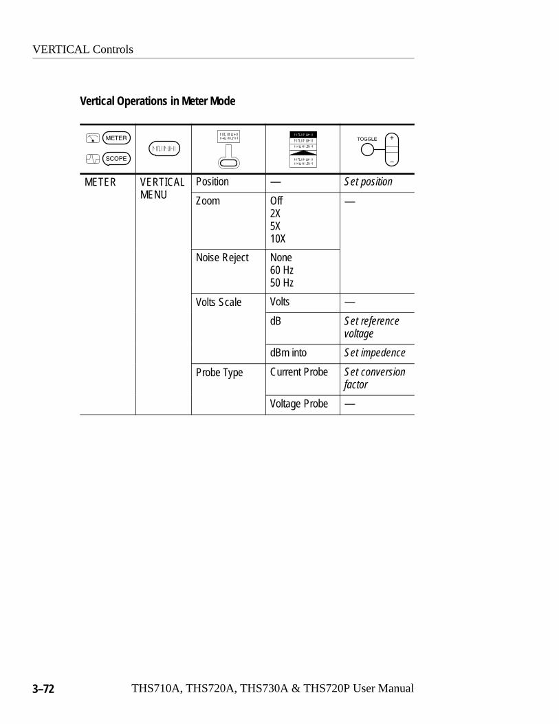
VERTICAL Controls
3–72 THS710A, THS720A, THS730A & THS720P User Manual
Vertical Operations in Meter Mode
METER VERTICALNU
Position — Set positionMENU Zoom Off
2X5X10X
—
Noise Reject None60 Hz50 Hz
Volts Scale Volts —
dB Set referencevoltage
dBm into Set impedence
Probe Type Current Probe Set conversionfactor
Voltage Probe —
VERTICAL Controls
THS710A, THS720A, THS730A & THS720P User Manual 3–73
Key Points
Zoom. You can get a close view of the data logger plot using theZoom selection. The plot is vertically enlarged around the center ofthe screen for the VDC function, and around the bottom of the screenfor other meter functions. Before you choose Zoom, you can choosePosition or use the vertical POSITION rocker to move the plot.
Noise Reject. You can improve the repeatability of AC measurementsin the presence of 50 Hz or 60 Hz noise by choosing noise rejection.
Volts Scale. If you choose dB, the current measurements, statistics,and logger data are shown in dB. If you choose dBm, you can set theimpedance.
VOLTS/DIV Rocker. Use the VOLTS/DIV rocker to change the meterrange and the vertical scale of the data logger plot.
POSITION Rocker. Use the vertical POSITION rocker to position thedata logger plot.

VERTICAL Controls
3–74 THS710A, THS720A, THS730A & THS720P User Manual

Appendices

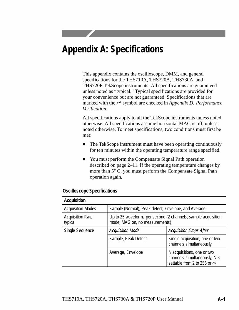
THS710A, THS720A, THS730A & THS720P User Manual A–1
Appendix A: Specifications
This appendix contains the oscilloscope, DMM, and generalspecifications for the THS710A, THS720A, THS730A, andTHS720P TekScope instruments. All specifications are guaranteedunless noted as “typical.” Typical specifications are provided foryour convenience but are not guaranteed. Specifications that aremarked with the � symbol are checked in Appendix D: PerformanceVerification.
All specifications apply to all the TekScope instruments unless notedotherwise. All specifications assume horizontal MAG is off, unlessnoted otherwise. To meet specifications, two conditions must first bemet:
� The TekScope instrument must have been operating continuouslyfor ten minutes within the operating temperature range specified.
� You must perform the Compensate Signal Path operationdescribed on page 2–11. If the operating temperature changes bymore than 5° C, you must perform the Compensate Signal Pathoperation again.
Oscilloscope Specifications
Acquisition
Acquisition Modes Sample (Normal), Peak detect, Envelope, and Average
Acquisition Rate, typical
Up to 25 waveforms per second (2 channels, sample acquisitionmode, MAG on, no measurements)
Single Sequence Acquisition Mode Acquisition Stops After
Sample, Peak Detect Single acquisition, one or twochannels simultaneously
Average, Envelope N acquisitions, one or twochannels simultaneously, N issettable from 2 to 256 or ∞

Appendix A: Specifications
A–2 THS710A, THS720A, THS730A & THS720P User Manual
Oscilloscope Specifications (Cont.)
Inputs
Input Coupling DC, AC, or GND
Input Impedance,DC Coupled
1 M� ±1% in parallel with 25 pF ±2 pF
Maximum VoltageBe ee d
Overvoltage Category Maximum VoltageBetween Signal andCommon at Input BNC CAT II Environment (refer to
page A–19)300 VRMS
CAT III Environment (refer topage A–19)
150 VRMS
For steady-state sinusoidal waveforms, derate at 20 dB/decadeabove 100 kHz to 13 Vpk at 3 MHz and above. Also, refer toOvervoltage Category description on page A–19.
Maximum VoltageBetween Common andEarth Ground at BNC
600 VRMS (CAT II) or 300 VRMS (CAT III), using rated connectorsor accessories
30 VRMS, 42.4 Vpk, using noninsulated connectors or accessories
Maximum Voltage,Channel-to-ChannelCommons
30 VRMS, 42.4 Vpk, using noninsulated connectors or accessories
Channel-to-ChannelCommon Mode Rejection, typical
100:1 at frequencies ≤50 MHz, measured on MATH Ch1 – Ch2waveform, with test signal applied between signal and commonof both channels, and with the same VOLTS/DIV and couplingsettings on each channel
Channel-to-ChannelCrosstalk, typical
≥100:1 at 50 MHz, measured on one channel, with test signalapplied between signal and common of the other channel, andwith the same VOLTS/DIV and coupling settings on each channel
Common to ChassisCapacitance, typical
55 pF
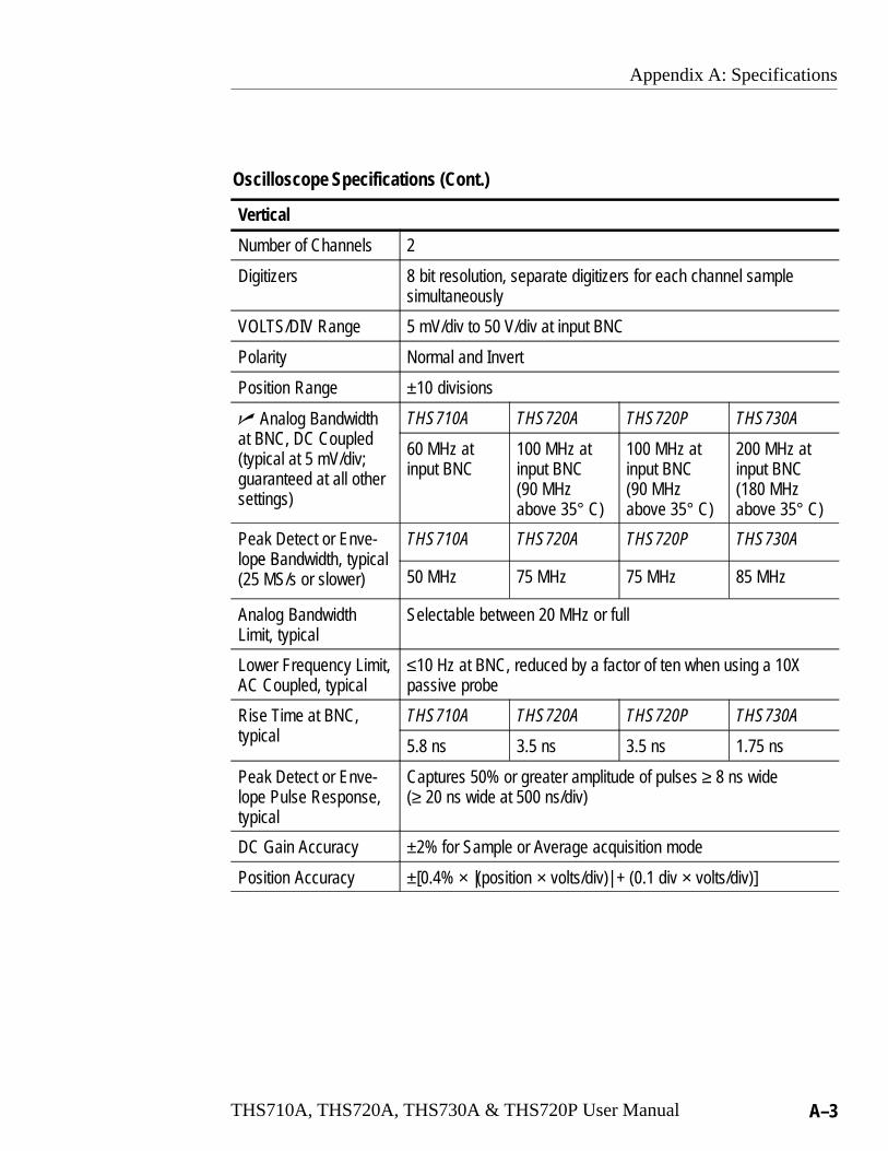
Appendix A: Specifications
THS710A, THS720A, THS730A & THS720P User Manual A–3
Oscilloscope Specifications (Cont.)
Vertical
Number of Channels 2
Digitizers 8 bit resolution, separate digitizers for each channel samplesimultaneously
VOLTS/DIV Range 5 mV/div to 50 V/div at input BNC
Polarity Normal and Invert
Position Range ±10 divisions
� Analog BandwidthBNC DC C ed
THS710A THS720A THS720P THS730Aat BNC, DC Coupled(typical at 5 mV/div;guaranteed at all othersettings)
60 MHz atinput BNC
100 MHz atinput BNC(90 MHzabove 35° C)
100 MHz atinput BNC(90 MHzabove 35° C)
200 MHz atinput BNC(180 MHzabove 35° C)
Peak Detect or Enve-e B d d
THS710A THS720A THS720P THS730Alope Bandwidth, typical(25 MS/s or slower) 50 MHz 75 MHz 75 MHz 85 MHz
Analog BandwidthLimit, typical
Selectable between 20 MHz or full
Lower Frequency Limit,AC Coupled, typical
≤10 Hz at BNC, reduced by a factor of ten when using a 10Xpassive probe
Rise Time at BNC, THS710A THS720A THS720P THS730Atypical
5.8 ns 3.5 ns 3.5 ns 1.75 ns
Peak Detect or Enve-lope Pulse Response,typical
Captures 50% or greater amplitude of pulses ≥ 8 ns wide(≥ 20 ns wide at 500 ns/div)
DC Gain Accuracy ±2% for Sample or Average acquisition mode
Position Accuracy ±[0.4% × |(position × volts/div)| + (0.1 div × volts/div)]
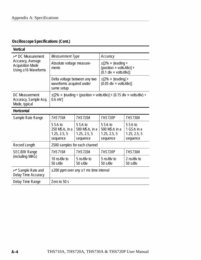
Appendix A: Specifications
A–4 THS710A, THS720A, THS730A & THS720P User Manual
Oscilloscope Specifications (Cont.)
Vertical
� DC MeasurementA r A er e
Measurement Type AccuracyAccuracy, AverageAcquisition Mode Using ≥16 Waveforms
Absolute voltage measure-ments
±[2% × |reading + (position × volts/div)| + (0.1 div × volts/div)]
Delta voltage between any twowaveforms acquired undersame setup
±[2% × |reading| + (0.05 div × volts/div)]
DC MeasurementAccuracy, Sample Acq.Mode, typical
±[2% × |reading + (position × volts/div)| + (0.15 div × volts/div) +0.6 mV]
Horizontal
Sample Rate Range THS710A THS720A THS720P THS730A
5 S/s to250 MS/s, in a1.25, 2.5, 5sequence
5 S/s to500 MS/s, in a1.25, 2.5, 5sequence
5 S/s to500 MS/s in a1.25, 2.5, 5sequence
5 S/s to1 GS/s in a1.25, 2.5, 5sequence
Record Length 2500 samples for each channel
SEC/DIV Ranged AG
THS710A THS720A THS720P THS730A(including MAG)
10 ns/div to50 s/div
5 ns/div to50 s/div
5 ns/div to50 s/div
2 ns/div to50 s/div
� Sample Rate andDelay Time Accuracy
±200 ppm over any ≥1 ms time interval
Delay Time Range Zero to 50 s

Appendix A: Specifications
THS710A, THS720A, THS730A & THS720P User Manual A–5
Oscilloscope Specifications (Cont.)
Internal Trigger
� Trigger Sensitivity,d e Tr er T e
Coupling SensitivityEdge Trigger Type(THS710A, THS 720A,and THS720P)
DC 0.35 div from DC to 50 MHz,increasing to 1 div at 100 MHz(90 MHz above 35° C)
� Trigger Sensitivity,d e Tr er T e
Coupling SensitivityEdge Trigger Type(THS730A) DC 0.35 div from DC to 50 MHz,
increasing to 1.5 div at200 MHz (180 MHz above35° C)
Trigger Sensitivity,d e Tr er T e
Coupling SensitivityEdge Trigger Type,
NOISE REJ 3.5 times the DC-coupled limitstypicalHF REJ 1.5 times the DC-coupled limit
from DC to 30 kHz, attenuatessignals above 30 kHz
LF REJ 1.5 times the DC-coupled limitsfor frequencies above 1 kHz,attenuates signals below 1 kHz
Trigger Level Range ±4 divisions from center of screen
Motor Trigger LevelRange (THS720P)
0.1 to 5 divisions from center of screen, polarity depends onslope selection
Trigger LevelAccuracy, typical
±0.2 divisions, for signals having rise and fall times ≥20 ns
SET LEVEL TO 50%,typical
Operates with input signals ≥50 Hz
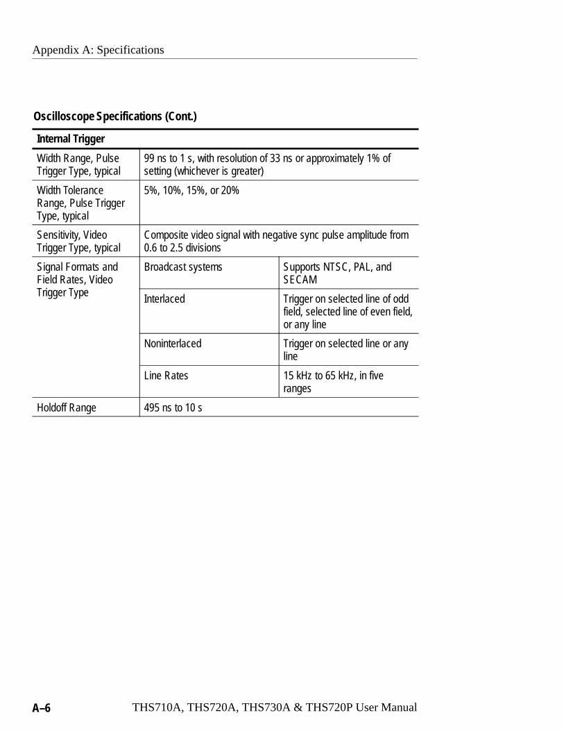
Appendix A: Specifications
A–6 THS710A, THS720A, THS730A & THS720P User Manual
Oscilloscope Specifications (Cont.)
Internal Trigger
Width Range, PulseTrigger Type, typical
99 ns to 1 s, with resolution of 33 ns or approximately 1% ofsetting (whichever is greater)
Width ToleranceRange, Pulse TriggerType, typical
5%, 10%, 15%, or 20%
Sensitivity, Video Trigger Type, typical
Composite video signal with negative sync pulse amplitude from0.6 to 2.5 divisions
Signal Formats andField Rates, VideoTr er T e
Broadcast systems Supports NTSC, PAL, andSECAM
Trigger Type Interlaced Trigger on selected line of oddfield, selected line of even field,or any line
Noninterlaced Trigger on selected line or anyline
Line Rates 15 kHz to 65 kHz, in fiveranges
Holdoff Range 495 ns to 10 s
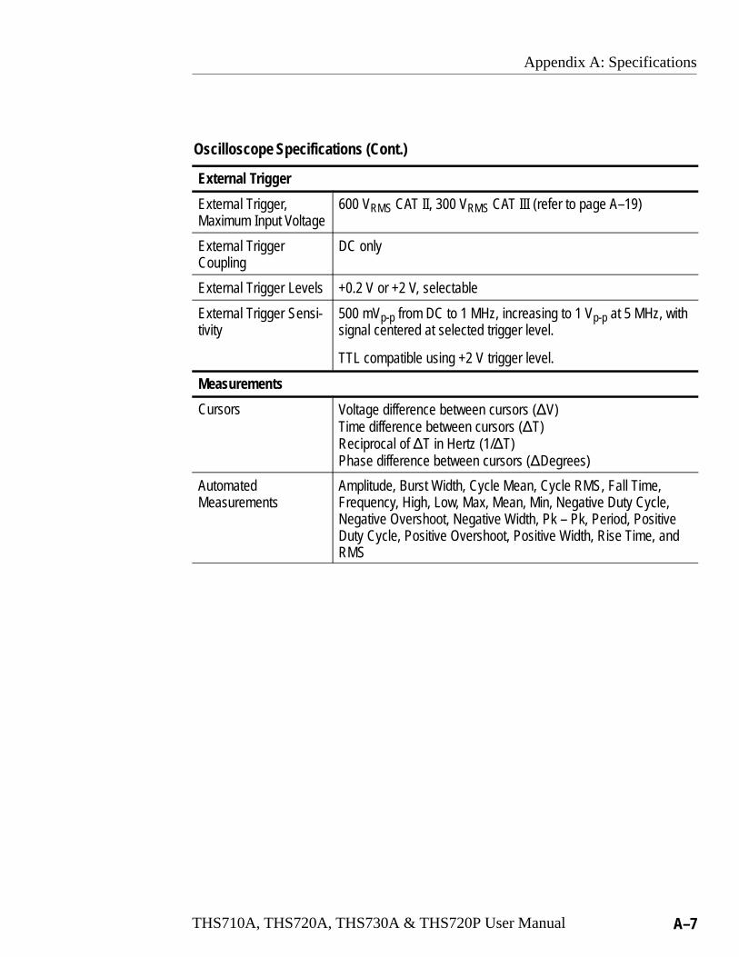
Appendix A: Specifications
THS710A, THS720A, THS730A & THS720P User Manual A–7
Oscilloscope Specifications (Cont.)
External Trigger
External Trigger, Maximum Input Voltage
600 VRMS CAT II, 300 VRMS CAT III (refer to page A–19)
External Trigger Coupling
DC only
External Trigger Levels +0.2 V or +2 V, selectable
External Trigger Sensi-tivity
500 mVp-p from DC to 1 MHz, increasing to 1 Vp-p at 5 MHz, withsignal centered at selected trigger level.
TTL compatible using +2 V trigger level.
Measurements
Cursors Voltage difference between cursors (�V)Time difference between cursors (�T)Reciprocal of �T in Hertz (1/�T)Phase difference between cursors (�Degrees)
Automated Measurements
Amplitude, Burst Width, Cycle Mean, Cycle RMS, Fall Time,Frequency, High, Low, Max, Mean, Min, Negative Duty Cycle,Negative Overshoot, Negative Width, Pk – Pk, Period, PositiveDuty Cycle, Positive Overshoot, Positive Width, Rise Time, andRMS
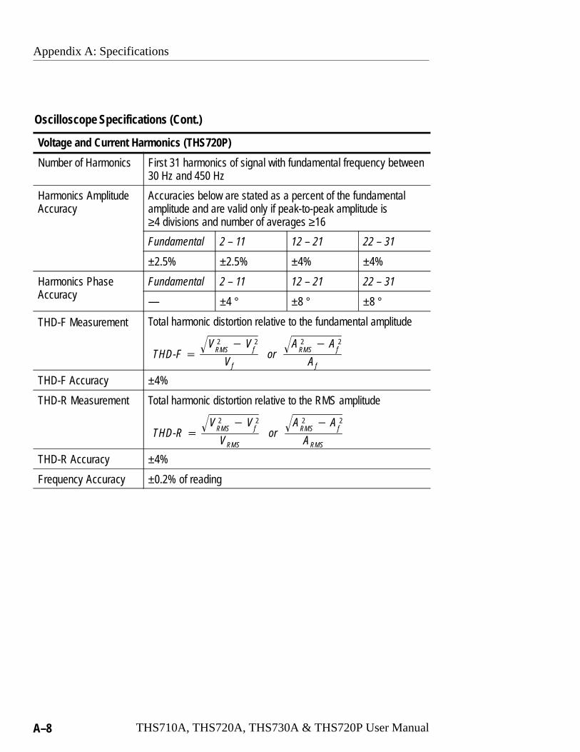
Appendix A: Specifications
A–8 THS710A, THS720A, THS730A & THS720P User Manual
Oscilloscope Specifications (Cont.)
Voltage and Current Harmonics (THS720P)
Number of Harmonics First 31 harmonics of signal with fundamental frequency between30 Hz and 450 Hz
Harmonics AmplitudeAccuracy
Accuracies below are stated as a percent of the fundamentalamplitude and are valid only if peak-to-peak amplitude is≥4 divisions and number of averages ≥16
Fundamental 2 – 11 12 – 21 22 – 31
±2.5% ±2.5% ±4% ±4%
Harmonics PhaseA r
Fundamental 2 – 11 12 – 21 22 – 31Accuracy
— ±4 ° ±8 ° ±8 °
THD-F Measurement Total harmonic distortion relative to the fundamental amplitude
THD-F �V 2
RMS� V 2
f�
Vfor
A 2RMS� A 2
f�
Af
THD-F Accuracy ±4%
THD-R Measurement Total harmonic distortion relative to the RMS amplitude
THD-R �V 2
RMS� V 2
f�
VRMSor
A 2RMS� A 2
f�
ARMS
THD-R Accuracy ±4%
Frequency Accuracy ±0.2% of reading
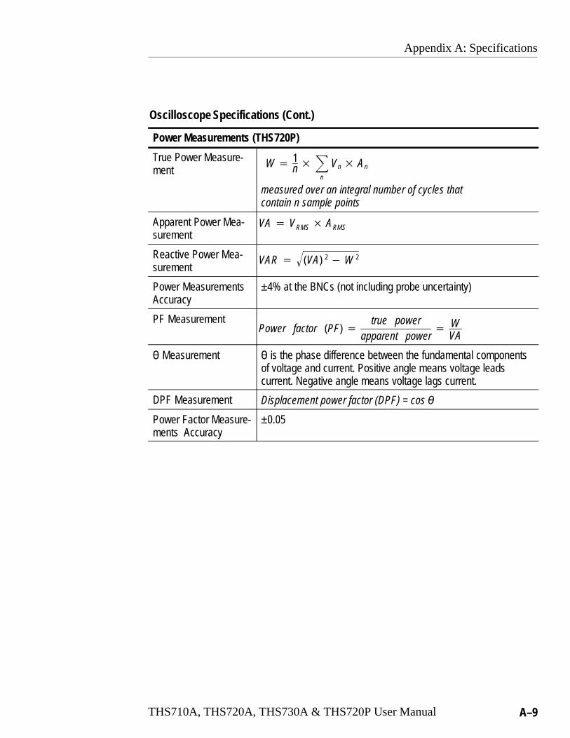
Appendix A: Specifications
THS710A, THS720A, THS730A & THS720P User Manual A–9
Oscilloscope Specifications (Cont.)
Power Measurements (THS720P)
True Power Measure-ment
W � 1n��
n
Vn� An
measured over an integral number of cycles that contain n sample points
Apparent Power Mea-surement
VA � VRMS� ARMS
Reactive Power Mea-surement
VAR � (VA) 2� W 2�
Power MeasurementsAccuracy
±4% at the BNCs (not including probe uncertainty)
PF MeasurementPower factor (PF) �
true powerapparent power
� WVA
� Measurement � is the phase difference between the fundamental componentsof voltage and current. Positive angle means voltage leadscurrent. Negative angle means voltage lags current.
DPF Measurement Displacement power factor (DPF) = cos �
Power Factor Measure-ments Accuracy
±0.05

Appendix A: Specifications
A–10 THS710A, THS720A, THS730A & THS720P User Manual
Oscilloscope Specifications (Cont.)
With P6117 Probe
Analog Bandwidth, DCC ed
THS710A THS720A THS720P THS730ACoupled
60 MHz 100 MHz(90 MHzabove 35° C)
100 MHz(90 MHzabove 35° C)
200 MHz(180 MHzabove 35° C)
Probe Attenuation 10X
Maximum VoltageBe ee r be T d
Overvoltage Category Maximum VoltageBetween Probe Tip andReference Lead CAT II Environment (refer to
page A–19)300 VRMS
CAT III Environment (refer topage A–19)
150 VRMS
For steady-state sinusoidal waveforms, derate at 20 dB/decadeabove 900 kHz to 13 VRMS at 27 MHz and above. Also, refer toOvervoltage Category description on page A–19.
Maximum VoltageBetween ReferenceLead and Earth GroundUsing P6117 Probe
30 VRMS, 42.4 Vpk
Maximum Voltage,Channel-to-ChannelReference Leads UsingP6117 Probes
30 VRMS, 42.4 Vpk
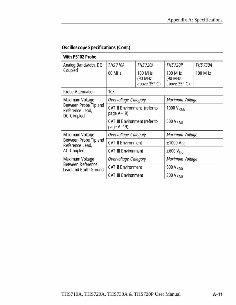
Appendix A: Specifications
THS710A, THS720A, THS730A & THS720P User Manual A–11
Oscilloscope Specifications (Cont.)
With P5102 Probe
Analog Bandwidth, DCC ed
THS710A THS720A THS720P THS730ACoupled
60 MHz 100 MHz(90 MHzabove 35° C)
100 MHz(90 MHzabove 35° C)
100 MHz
Probe Attenuation 10X
Maximum VoltageBe ee r be T d
Overvoltage Category Maximum VoltageBetween Probe Tip andReference Lead,DC C ed
CAT II Environment (refer topage A–19)
1000 VRMS
DC CoupledCAT III Environment (refer topage A–19)
600 VRMS
Maximum VoltageBe ee r be T d
Overvoltage Category Maximum VoltageBetween Probe Tip andRefere e e d CAT II Environment ±1000 VDCReference Lead,AC Coupled CAT III Environment ±600 VDC
Maximum VoltageBe ee Refere e
Overvoltage Category Maximum VoltageBetween Referencee d d r Gr d CAT II Environment 600 VRMSLead and Earth Ground
CAT III Environment 300 VRMS

Appendix A: Specifications
A–12 THS710A, THS720A, THS730A & THS720P User Manual
DMM Specifications
General
Resolution 33⁄4 digit, 4000 count full scale reading except as noted
Input Resistance, ACor DC Voltage
10 M� ±10%
Input Capacitance, ACor DC Voltage, typical
≤100 pF
Maximum VoltageBe ee D d
Overvoltage Category Maximum VoltageBetween DMM andCOM Inputs CAT I Environment (refer to
page A–19)640 VRMS (880 VDC)
CAT II Environment (refer topage A–19)
600 VRMS
CAT III Environment (refer topage A–19)
300 VRMS
Maximum VoltageBe ee D r CO
Overvoltage Category Maximum VoltageBetween DMM or COMInput and Earth Ground CAT I Environment (refer to
page A–19)640 VRMS (880 VDC)
CAT II Environment (refer topage A–19)
600 VRMS
CAT III Environment (refer topage A–19)
300 VRMS
DC Voltage
Ranges and Resolution Range Resolution
400.0 mV 0.1 mV
4.000 V 1 mV
40.00 V 10 mV
400.0 V 100 mV
880 V 1 V
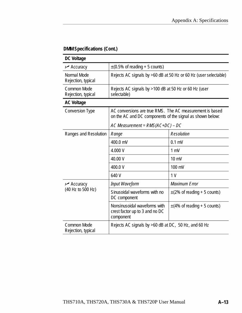
Appendix A: Specifications
THS710A, THS720A, THS730A & THS720P User Manual A–13
DMM Specifications (Cont.)
DC Voltage
� Accuracy ±(0.5% of reading + 5 counts)
Normal Mode Rejection, typical
Rejects AC signals by >60 dB at 50 Hz or 60 Hz (user selectable)
Common Mode Rejection, typical
Rejects AC signals by >100 dB at 50 Hz or 60 Hz (userselectable)
AC Voltage
Conversion Type AC conversions are true RMS. The AC measurement is basedon the AC and DC components of the signal as shown below:
AC Measurement = RMS(AC+DC) – DC
Ranges and Resolution Range Resolution
400.0 mV 0.1 mV
4.000 V 1 mV
40.00 V 10 mV
400.0 V 100 mV
640 V 1 V
� Accuracy0 00
Input Waveform Maximum Error(40 Hz to 500 Hz) Sinusoidal waveforms with no
DC component±(2% of reading + 5 counts)
Nonsinusoidal waveforms withcrest factor up to 3 and no DCcomponent
±(4% of reading + 5 counts)
Common Mode Rejection, typical
Rejects AC signals by >60 dB at DC, 50 Hz, and 60 Hz

Appendix A: Specifications
A–14 THS710A, THS720A, THS730A & THS720P User Manual
DMM Specifications (Cont.)
�/Resistance
Ranges and Resolution Range Resolution
400.0 � 0.1 �
4.000 k� 1 �
40.00 k� 10 �
400.0 k� 100 �
4.000 M� 1 k�
40.00 M� 10 k�
� Accuracy Range Maximum Error
All ranges except 40 M� ±(0.5% of reading + 2 counts)
40 M� ±(2% of reading + 5 counts) for≤60% relative humidity
Bias Voltage for Fulle Res s e
Range Full Scale Bias VoltageScale Resistance
e s reme 400.0 � 350 mVMeasurement, typical4.000 k� 200 mV
40.00 k� 350 mV
400.0 k� 350 mV
4.000 M� 400 mV
40.00 M� 1.10 V
Open Circuit Voltage, Range Open Circuit Voltagetypical
400.0 � 4.8 V
All other ranges ≤1.2 V

Appendix A: Specifications
THS710A, THS720A, THS730A & THS720P User Manual A–15
DMM Specifications (Cont.)
Continuity Check
Indication, typical An audible tone is generated when measured resistance is below50 �
Open Circuit Voltage,typical
4 V
Test Current, typical 1 mA
Diode Check
Range Zero to 2 V, measures forward voltage drop of semiconductorjunction
Voltage Accuracy, typical
±25%
Open Circuit Voltage,typical
4 V
Test Current, typical 1 mA
Data Logger
Horizontal ScaleRange
30 s/div to 24 hours/div (4 minutes to 8 days, full scale)
Vertical Zoom Range 2X, 5X, or 10X
General Specifications
Display
Display Type 4.7 in (120 mm) diagonal liquid crystal
Display Resolution 320 horizontal by 240 vertical pixels
Display Contrast Adjustable, temperature compensated
Backlight Intensity,typical
35 cd/m2
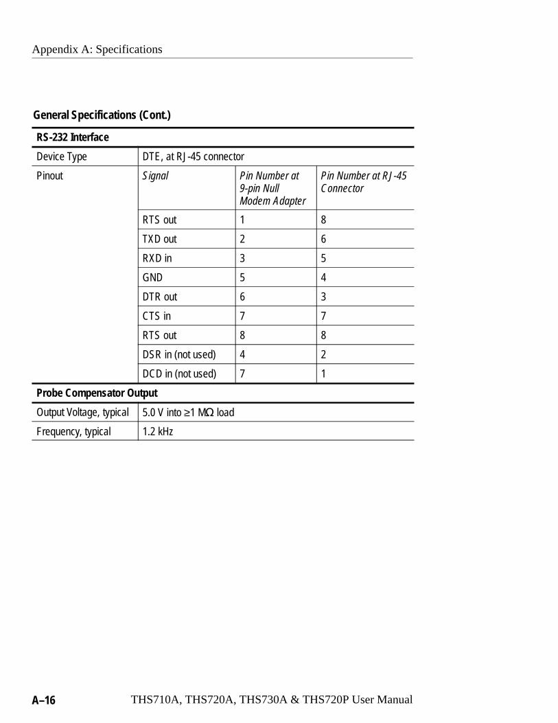
Appendix A: Specifications
A–16 THS710A, THS720A, THS730A & THS720P User Manual
General Specifications (Cont.)
RS-232 Interface
Device Type DTE, at RJ-45 connector
Pinout Signal Pin Number at9-pin NullModem Adapter
Pin Number at RJ-45Connector
RTS out 1 8
TXD out 2 6
RXD in 3 5
GND 5 4
DTR out 6 3
CTS in 7 7
RTS out 8 8
DSR in (not used) 4 2
DCD in (not used) 7 1
Probe Compensator Output
Output Voltage, typical 5.0 V into ≥1 M� load
Frequency, typical 1.2 kHz

Appendix A: Specifications
THS710A, THS720A, THS730A & THS720P User Manual A–17
General Specifications (Cont.)
Power Source
Battery Replaceable Ni-Cd battery pack
Battery Life, typical Approximately two hours of continuous use from a full charge
Low Battery Indication,typical
Low battery message first appears approximately ten minutesbefore the instrument powers off automatically
Battery Saver Standby Time-out and Backlight Time-out extend battery life.Time-out ranges from 1 minute to 15 minutes, or off.
Battery Charging Time,typical
With TekScopeinstrument operating
9 hours
With TekScopeinstrument turned off
9 hours
In external charger 1.5 hours
External Power 12 VDC nominal, center positive; Operates with input from10 VDC to 15 VDC
The DC INPUT disconnects itself automatically if >15 VDC isapplied. If this occurs, disconnect the overvoltage and thenreconnect to a voltage in the proper range.
Memory Retention,typical
All memory is retained indefinitely with battery removed andwithout external power applied.
Fuse This instrument has no user-replaceable fuses

Appendix A: Specifications
A–18 THS710A, THS720A, THS730A & THS720P User Manual
General Specifications (Cont.)
Environmental
Temperature Operating –10° C to +50° C
Nonoperating –20° C to +60° C
Humidity +40° C or below ≤95% relative humidity
+41° C to +50° C ≤75% relative humidity
Altitude Operating 2,000 m
Nonoperating 15,000 m
Random Vibration Operating 2.66 gRMS from 5 Hz to 500 Hz, 10 min-utes on each axis
Nonoperating 3.48 gRMS from 5 Hz to 500 Hz, 10 min-utes on each axis
Drop Resistance, typical
Survives a 30 in (76 cm) drop onto concrete with only cosmeticdamage
Moisture Resistance Meets IEC529, IP43 with DC input hole plug, I/O port hole plug,and battery door installed.
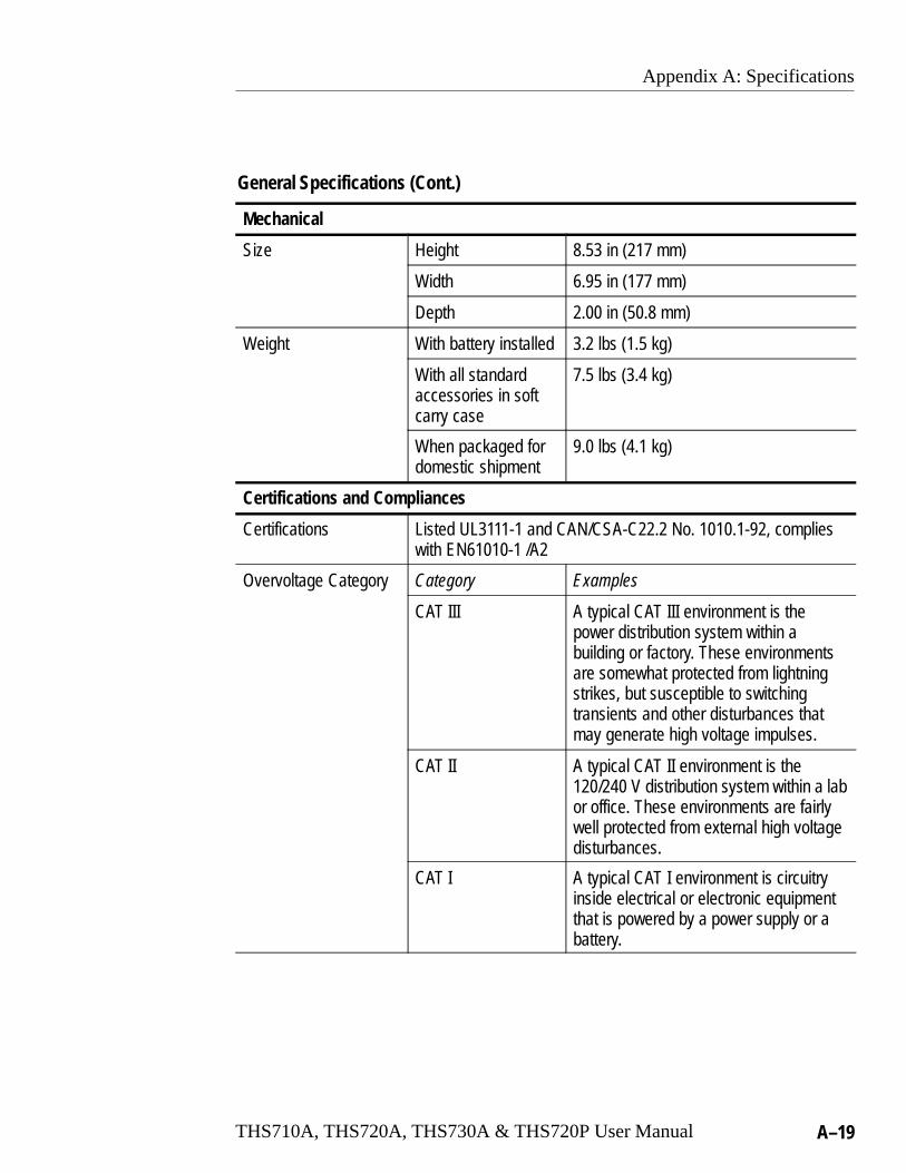
Appendix A: Specifications
THS710A, THS720A, THS730A & THS720P User Manual A–19
General Specifications (Cont.)
Mechanical
Size Height 8.53 in (217 mm)
Width 6.95 in (177 mm)
Depth 2.00 in (50.8 mm)
Weight With battery installed 3.2 lbs (1.5 kg)
With all standardaccessories in softcarry case
7.5 lbs (3.4 kg)
When packaged fordomestic shipment
9.0 lbs (4.1 kg)
Certifications and Compliances
Certifications Listed UL3111-1 and CAN/CSA-C22.2 No. 1010.1-92, complieswith EN61010-1 /A2
Overvoltage Category Category Examples
CAT III A typical CAT III environment is thepower distribution system within abuilding or factory. These environmentsare somewhat protected from lightningstrikes, but susceptible to switchingtransients and other disturbances thatmay generate high voltage impulses.
CAT II A typical CAT II environment is the120/240 V distribution system within a labor office. These environments are fairlywell protected from external high voltagedisturbances.
CAT I A typical CAT I environment is circuitryinside electrical or electronic equipmentthat is powered by a power supply or abattery.

Appendix A: Specifications
A–20 THS710A, THS720A, THS730A & THS720P User Manual
General Specifications (Cont.)
Certifications and Compliances
EC Declaration of Conformity
Meets the intent of Directive 89/336/EEC for ElectromagneticCompatibility and Low-Voltage Directive 73/23/ECC for ProductSafety as amended by 93/68/EEC. Compliance was demon-strated to the following specifications as listed in the officialJournal of the European Communities:
EN 55011 Class A: Radiated and Conducted Emissions1 3
EN 50081–1 Emissions:EN 60555–2 Power Harmonics
EN 50082–1 Immunity:IEC 801–2 Electrostatic DischargeIEC 801–3 RF Radiated2
IEC 801–4 Fast TransientsIEC 801–5 Surge3
EN 61010–1 /A2 Safety
1 Tektronix-supplied ferrite bead required on instrument end ofRS-232 cable
2 Performance criteria: ≤ 5.0 div increase in peak-to-peaknoise (Sample acquisition mode, full bandwidth); otherwise,≤ 1.0 div increase in peak-to-peak noise
3 Applies to instrument operating from Tektronix-supplied ACadapter
Adjustment Interval
The recommended adjustment interval is one year

THS710A, THS720A, THS730A & THS720P User Manual B–1
Appendix B: Factory Setup
The table below lists the state of the TekScope instrument after yourecall the Factory Setup.
Control Changed by Factory Setup to
Acquire mode Sample
Acquire stop after HOLD button only
Acquire # of averages 16
Acquire # of envelopes 8
Channel selection Channel 1 on, all others off
Cursor H Bar 1 position –3.2 divisions from the center
Cursor H Bar 2 position +3.2 divisions from the center
Cursor V Bar 1 position –2 divisions from the center
Cursor V Bar 2 position +2 divisions from the center
Cursor function Off
Cursor time units Seconds
Delayed time base time/div 50 �s/div
Delay time, delayed runs after main 200 ns
Data logger position 0 V
Data logger rate 30 s/div
Data logger zoom Off
dB reference voltage 1 V
dBm into impedance 50 �
Display format YT
Display graticule type Full
Display contrast 50%
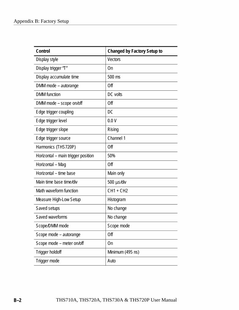
Appendix B: Factory Setup
B–2 THS710A, THS720A, THS730A & THS720P User Manual
Control Changed by Factory Setup to
Display style Vectors
Display trigger “T” On
Display accumulate time 500 ms
DMM mode – autorange Off
DMM function DC volts
DMM mode – scope on/off Off
Edge trigger coupling DC
Edge trigger level 0.0 V
Edge trigger slope Rising
Edge trigger source Channel 1
Harmonics (THS720P) Off
Horizontal – main trigger position 50%
Horizontal – Mag Off
Horizontal – time base Main only
Main time base time/div 500 �s/div
Math waveform function CH1 + CH2
Measure High-Low Setup Histogram
Saved setups No change
Saved waveforms No change
Scope/DMM mode Scope mode
Scope mode – autorange Off
Scope mode – meter on/off On
Trigger holdoff Minimum (495 ns)
Trigger mode Auto

Appendix B: Factory Setup
THS710A, THS720A, THS730A & THS720P User Manual B–3
Control Changed by Factory Setup to
Trigger type Edge
Vertical bandwidth (all channels) Full
Vertical coupling (all channels) DC
Vertical position (all channels) 0 div
Vertical volts/div. (all channels) 100 mV/div
Volts scale Volts

Appendix B: Factory Setup
B–4 THS710A, THS720A, THS730A & THS720P User Manual

THS710A, THS720A, THS730A & THS720P User Manual C–1
Appendix C: Accessories
Standard Accessories
P6117 10X Passive Probes (THS730A, THS720A, and THS710A)
The P6117 10X passive probes have 200 MHz bandwidth and aCAT II voltage rating of 300 VRMS. These probes are suitable forfloating measurements up to 30 VRMS.
P5102 10X Passive Probes (THS720P)
The P5102 10X passive probes have 100 MHz bandwidth and aCAT II voltage rating of 1000 VRMS. These probes are suitable forfloating measurements up to 600 VRMS.
Meter Lead Set
The standard pair of meter leads (012-1482-00) provides sharptips for probing, two screw-on plunger tips for grabbing test pointsor small conductors, and two screw-on insulated alligator clips forgrabbing terminals or larger conductors.
Battery Pack
The TekScope instrument includes one high-capacity (4.8 V,2.8 A⋅hr), rechargeable battery pack. Refer to THS7BAT onpage C–3.
AC Power Adapter
The AC power adapter allows operation from the AC power lineand charges the internal battery. (North American 119-4812-XX,Universal European 119-4813-XX, United Kingdom 119-4922-XX,Japan 119-4923-XX)
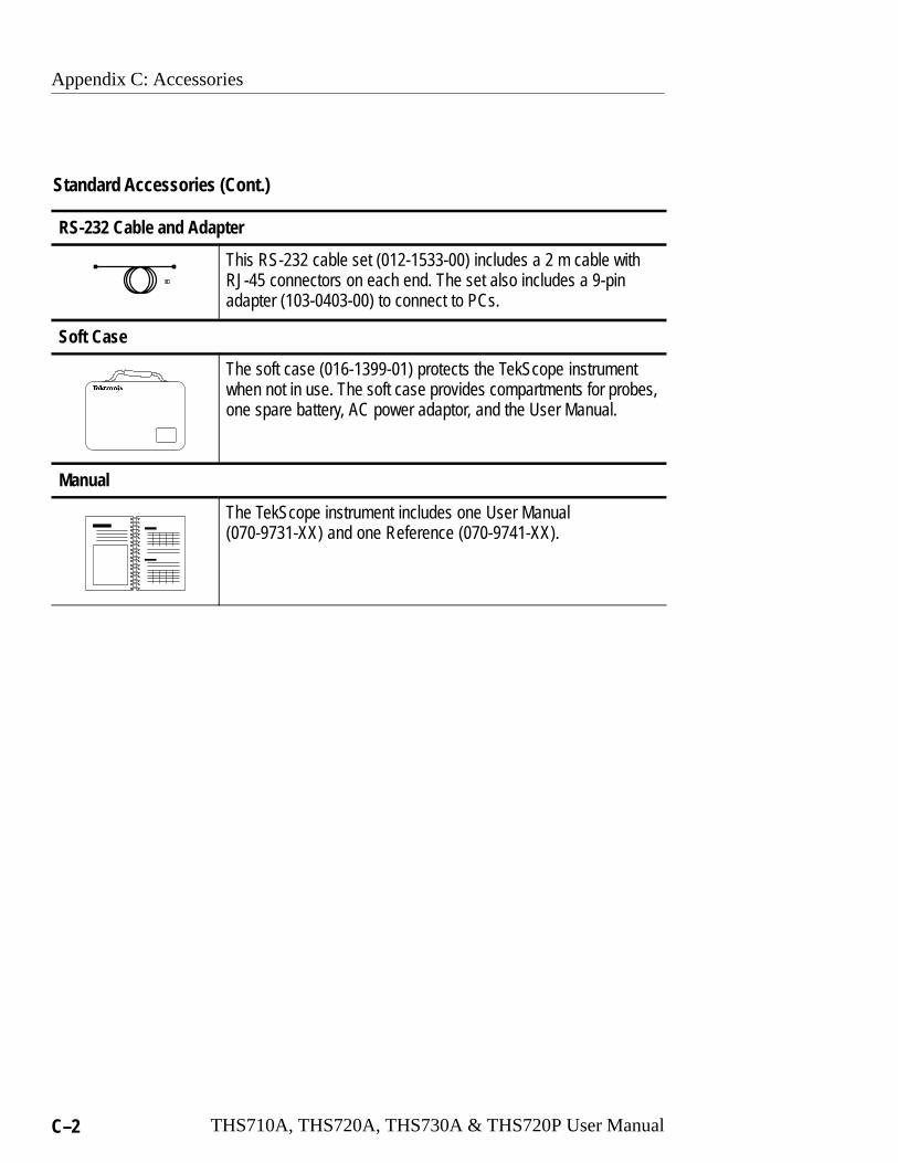
Appendix C: Accessories
C–2 THS710A, THS720A, THS730A & THS720P User Manual
Standard Accessories (Cont.)
RS-232 Cable and Adapter
This RS-232 cable set (012-1533-00) includes a 2 m cable withRJ-45 connectors on each end. The set also includes a 9-pinadapter (103-0403-00) to connect to PCs.
Soft Case
The soft case (016-1399-01) protects the TekScope instrumentwhen not in use. The soft case provides compartments for probes,one spare battery, AC power adaptor, and the User Manual.
Manual
The TekScope instrument includes one User Manual(070-9731-XX) and one Reference (070-9741-XX).
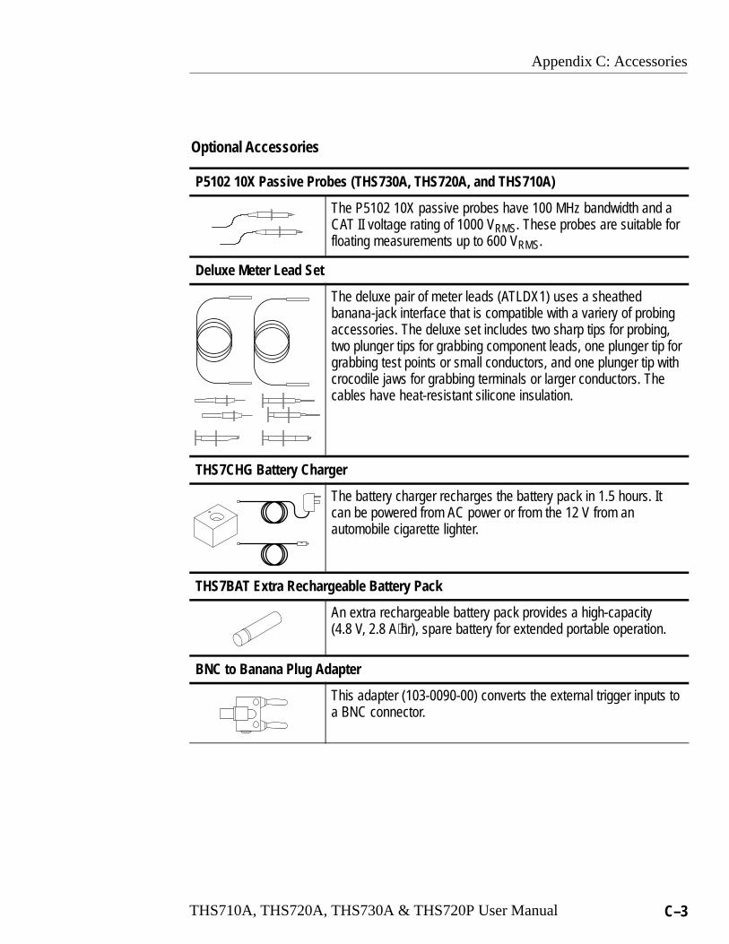
Appendix C: Accessories
THS710A, THS720A, THS730A & THS720P User Manual C–3
Optional Accessories
P5102 10X Passive Probes (THS730A, THS720A, and THS710A)
The P5102 10X passive probes have 100 MHz bandwidth and aCAT II voltage rating of 1000 VRMS. These probes are suitable forfloating measurements up to 600 VRMS.
Deluxe Meter Lead Set
The deluxe pair of meter leads (ATLDX1) uses a sheathedbanana-jack interface that is compatible with a variery of probingaccessories. The deluxe set includes two sharp tips for probing,two plunger tips for grabbing component leads, one plunger tip forgrabbing test points or small conductors, and one plunger tip withcrocodile jaws for grabbing terminals or larger conductors. Thecables have heat-resistant silicone insulation.
THS7CHG Battery Charger
The battery charger recharges the battery pack in 1.5 hours. Itcan be powered from AC power or from the 12 V from anautomobile cigarette lighter.
THS7BAT Extra Rechargeable Battery Pack
An extra rechargeable battery pack provides a high-capacity(4.8 V, 2.8 A⋅hr), spare battery for extended portable operation.
BNC to Banana Plug Adapter
This adapter (103-0090-00) converts the external trigger inputs toa BNC connector.
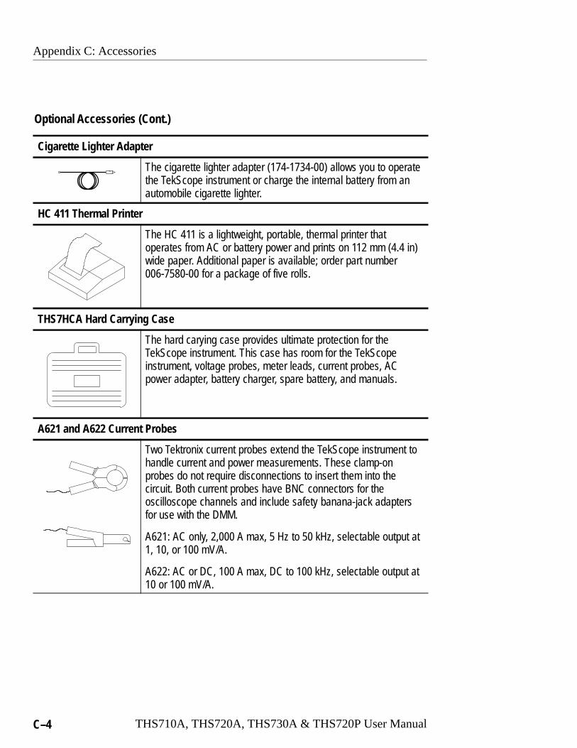
Appendix C: Accessories
C–4 THS710A, THS720A, THS730A & THS720P User Manual
Optional Accessories (Cont.)
Cigarette Lighter Adapter
The cigarette lighter adapter (174-1734-00) allows you to operatethe TekScope instrument or charge the internal battery from anautomobile cigarette lighter.
HC 411 Thermal Printer
The HC 411 is a lightweight, portable, thermal printer thatoperates from AC or battery power and prints on 112 mm (4.4 in)wide paper. Additional paper is available; order part number006-7580-00 for a package of five rolls.
THS7HCA Hard Carrying Case
The hard carying case provides ultimate protection for theTekScope instrument. This case has room for the TekScopeinstrument, voltage probes, meter leads, current probes, ACpower adapter, battery charger, spare battery, and manuals.
A621 and A622 Current Probes
Two Tektronix current probes extend the TekScope instrument tohandle current and power measurements. These clamp-onprobes do not require disconnections to insert them into thecircuit. Both current probes have BNC connectors for theoscilloscope channels and include safety banana-jack adaptersfor use with the DMM.
A621: AC only, 2,000 A max, 5 Hz to 50 kHz, selectable output at1, 10, or 100 mV/A.
A622: AC or DC, 100 A max, DC to 100 kHz, selectable output at10 or 100 mV/A.
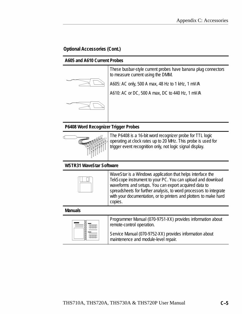
Appendix C: Accessories
THS710A, THS720A, THS730A & THS720P User Manual C–5
Optional Accessories (Cont.)
A605 and A610 Current Probes
These busbar-style current probes have banana plug connectorsto measure current using the DMM.
A605: AC only, 500 A max, 48 Hz to 1 kHz, 1 mV/A
A610: AC or DC, 500 A max, DC to 440 Hz, 1 mV/A
P6408 Word Recognizer Trigger Probes
The P6408 is a 16-bit word recognizer probe for TTL logicoperating at clock rates up to 20 MHz. This probe is used fortrigger event recognition only, not logic signal display.
WSTR31 WaveStar Software
WaveStar is a Windows application that helps interface theTekScope instrument to your PC. You can upload and downloadwaveforms and setups. You can export acquired data tospreadsheets for further analysis, to word processors to integratewith your documentation, or to printers and plotters to make hardcopies.
Manuals
Programmer Manual (070-9751-XX) provides information aboutremote-control operation.
Service Manual (070-9752-XX) provides information aboutmaintenence and module-level repair.

Appendix C: Accessories
C–6 THS710A, THS720A, THS730A & THS720P User Manual
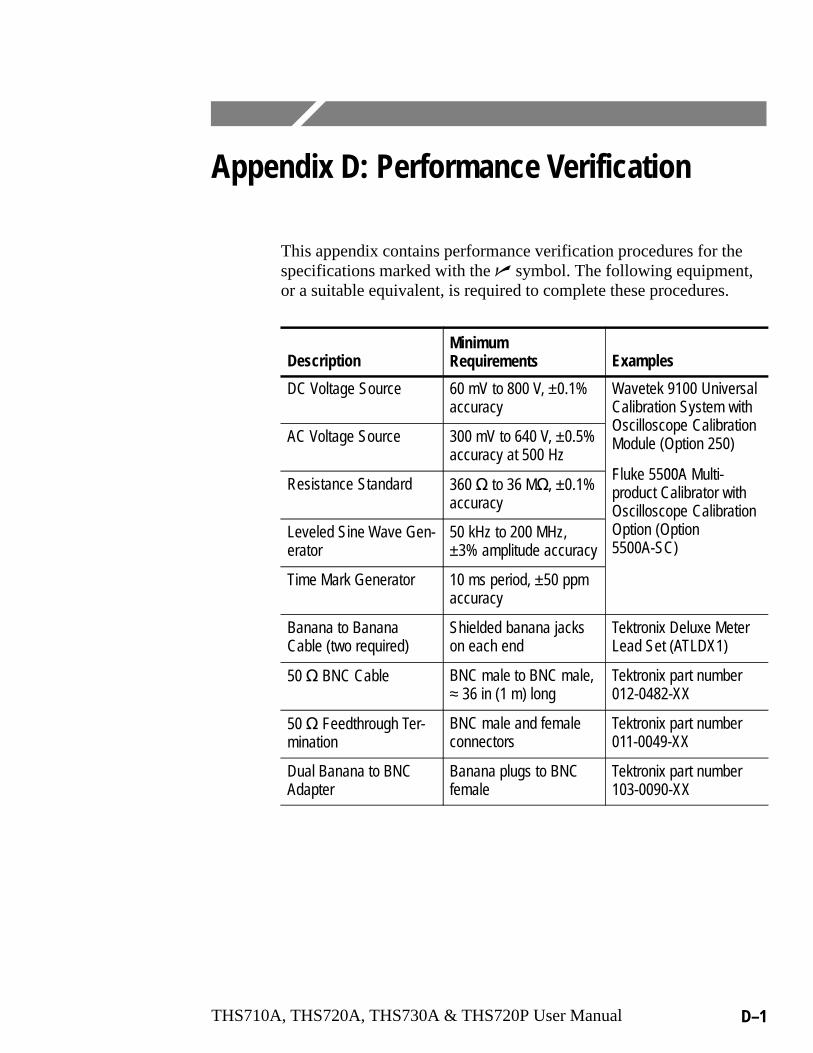
THS710A, THS720A, THS730A & THS720P User Manual D–1
Appendix D: Performance Verification
This appendix contains performance verification procedures for thespecifications marked with the � symbol. The following equipment,or a suitable equivalent, is required to complete these procedures.
DescriptionMinimum Requirements Examples
DC Voltage Source 60 mV to 800 V, ±0.1%accuracy
Wavetek 9100 UniversalCalibration System withOs s e C br
AC Voltage Source 300 mV to 640 V, ±0.5%accuracy at 500 Hz
Oscilloscope CalibrationModule (Option 250)
F e 00AResistance Standard 360 � to 36 M�, ±0.1%
accuracy
Fluke 5500A Multi-product Calibrator withOscilloscope Calibration
Leveled Sine Wave Gen-erator
50 kHz to 200 MHz,±3% amplitude accuracy
Os s e C brOption (Option5500A-SC)
Time Mark Generator 10 ms period, ±50 ppmaccuracy
Banana to BananaCable (two required)
Shielded banana jackson each end
Tektronix Deluxe MeterLead Set (ATLDX1)
50 � BNC Cable BNC male to BNC male,≈ 36 in (1 m) long
Tektronix part number012-0482-XX
50 � Feedthrough Ter-mination
BNC male and femaleconnectors
Tektronix part number011-0049-XX
Dual Banana to BNCAdapter
Banana plugs to BNCfemale
Tektronix part number103-0090-XX

Appendix D: Performance Verification
D–2 THS710A, THS720A, THS730A & THS720P User Manual
Test Record
Serial Number Procedure Performed by Date
Test Passed Failed
Self Test
Oscilloscope Tests Low Limit Test Result High Limit
Channel 1DC e s re
5 mV/div 34.05 mV 35.95 mVDC Measure-ment Accu-r
500 mV/div 3.405 V 3.595 Vme Aracy 2 V/div 13.62 V 14.38 V
10 V/div 68.1 V 71.9 V
Channel 2DC e s re
5 mV/div 34.05 mV 35.95 mVDC Measure-ment Accu-r
500 mV/div 3.405 V 3.595 Vme Aracy 2 V/div 13.62 V 14.38 V
10 V/div 68.1 V 71.9 V
Channel 1 Bandwidth 425 mV —
Channel 2 Bandwidth 425 mV —
Sample Rate and Delay TimeAccuracy
–4 divs +4 divs
Channel 1 Edge TriggerSensitivity
Stable trigger —
Channel 2 Edge TriggerSensitivity
Stable trigger —
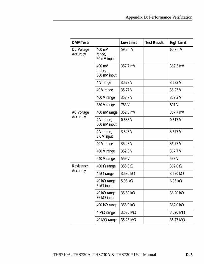
Appendix D: Performance Verification
THS710A, THS720A, THS730A & THS720P User Manual D–3
DMM Tests Low Limit Test Result High Limit
DC VoltageAccuracy
400 mVrange,60 mV input
59.2 mV 60.8 mV
400 mVrange,360 mV input
357.7 mV 362.3 mV
4 V range 3.577 V 3.623 V
40 V range 35.77 V 36.23 V
400 V range 357.7 V 362.3 V
880 V range 783 V 801 V
AC VoltageA r
400 mV range 352.3 mV 367.7 mVAccuracy
4 V range,600 mV input
0.583 V 0.617 V
4 V range,3.6 V input
3.523 V 3.677 V
40 V range 35.23 V 36.77 V
400 V range 352.3 V 367.7 V
640 V range 559 V 593 V
ResistanceA r
400 � range 358.0 � 362.0 �Accuracy
4 k� range 3.580 k� 3.620 k�
40 k� range,6 k� input
5.95 k� 6.05 k�
40 k� range,36 k� input
35.80 k� 36.20 k�
400 k� range 358.0 k� 362.0 k�
4 M� range 3.580 M� 3.620 M�
40 M� range 35.23 M� 36.77 M�
Appendix D: Performance Verification
D–4 THS710A, THS720A, THS730A & THS720P User Manual
Performance Verification ProceduresBefore beginning these procedures, two conditions must first be met:
� The TekScope instrument must have been operating continuouslyfor ten minutes in an 18° C to 28° C ambient environment with arelative humidity of less than 60%.
� You must perform the Compensate Signal Path operationdescribed on page 2–11. If the operating temperature changes bymore than 5° C, you must perform the Compensate Signal Pathoperation again.
The time required to complete the entire procedure is approximatelyone hour.
WARNING. Some procedures use hazardous voltages. To preventelectrical shock, always set voltage source outputs to 0 V beforemaking or changing any interconnections.

Appendix D: Performance Verification
THS710A, THS720A, THS730A & THS720P User Manual D–5
Self Test
This procedure uses internal routines to verify that the TekScopeinstrument functions and passes its internal self tests. No testequipment or hookups are required. Start the self test with thefollowing setup:
SCOPE UTILITY System Diag
Loop Once
Execute —
OK Run Test
A dialog box displays the result when the self test completes. Pressthe CLEAR MENU button to continue operation.

Appendix D: Performance Verification
D–6 THS710A, THS720A, THS730A & THS720P User Manual
Check DC Measurement Accuracy1. Set the DC voltage source output level to 0 V.
2. Set up the TekScope instrument using the following steps:
SCOPE SAVE/RECALL
Recall SavedSetup
Recall FactorySetup
—
OK Recall Factory
—
CH 1 —
VERTICALMENU
Probe Type Voltage Probe Set to 1X
ACQUIRE Acquire Mode Average Set to 16
MEAS SelectMeasrmnt
Mean* —
OK SelectMeasrmnt
—
* You may need to press Select Page to display this selection.
3. Connect the TekScope instrument to the DC voltage source asshown below.
+–
DC voltagesource Ch 1
Dual bananato bnc adapter
BNC cable

Appendix D: Performance Verification
THS710A, THS720A, THS730A & THS720P User Manual D–7
4. For each VOLTS/DIV setting listed below, perform the followingsteps:
a. Set the DC voltage source output level to the positivevoltage listed and then record the mean measurementas Vpos.
b. Reverse the polarity of the DC voltage source and thenrecord the mean measurement as Vneg.
c. Calculate Vdiff = Vpos – Vneg and then compare Vdiff tothe accuracy limits in the table.
VOLTS/DIV SettingDC Voltage SourceOutput Levels
Accuracy Limitsfor Vdiff
5 mV/div +17.5 mV, –17.5 mV 34.05 mV to 35.95 mV
500 mV/div +1.75 V, –1.75 V 3.405 V to 3.595 V
2 V/div +7.00 V, –7.00 V 13.62 V to 14.38 V
10 V/div +35.0 V, –35.0 V 68.1 V to 71.9 V
5. Set DC voltage source output level to 0 V.
6. To check channel 2, repeat step 2 substituting CH 2 for CH 1.
7. Press CH 1 and WAVEFORM OFF to remove the channel 1waveform from the display.
8. Repeat steps 3 through 5, substituting CH 2 for CH 1, to completethe check of channel 2.

Appendix D: Performance Verification
D–8 THS710A, THS720A, THS730A & THS720P User Manual
Check Channel 1 Bandwidth1. Set up the TekScope instrument using the following steps:
SCOPE SAVE/RECALL
Recall SavedSetup
Recall FactorySetup
—
OK Recall Factory
—
ACQUIRE Acquire Mode Average Set to 16
TRIGGER Trigger Coupling
Noise Reject —
MEAS Gating & High-Low Setup
High-LowMethod
Min/Max
SelectMeasrmnt
Pk-Pk* —
OK SelectMeasrmnt
—
* You may need to press Select Page to display this selection.
2. Connect the TekScope instrument to the leveled sine wavegenerator as shown below.
Leveledsine wavegenerator Ch 1
Output
50 � feedthroughterminator
BNC cable
Appendix D: Performance Verification
THS710A, THS720A, THS730A & THS720P User Manual D–9
3. Set the TekScope instrument VOLTS/DIV to 100 mV/div.
4. Set the TekScope instrument SEC/DIV to 10 �s/div.
5. Set the leveled sine wave generator frequency to 50 kHz.
6. Set the leveled sine wave generator output level so the peak-to-peak measurement is between 599 mV and 601 mV.
7. Set the leveled sine wave generator frequency to 200 MHz if youare checking a THS730A, 100 MHz if you are checking aTHS720A or a THS720P, or 60 MHz if you are checking aTHS710A.
8. Press MAG .
9. Set the TekScope instrument SEC/DIV to 10 ns/div.
10.Check that the peak-to-peak measurement is ≥425 mV.
11.Press MAG .
12.Proceed to the next test to check the channel 2 bandwidth.

Appendix D: Performance Verification
D–10 THS710A, THS720A, THS730A & THS720P User Manual
Check Channel 2 Bandwidth1. First check the channel 1 bandwidth using the previous test.
Then, perform these additional steps to check the channel 2bandwidth:
SCOPE CH 1 — — —
WAVE-FORMOFF
CH 2
TRIGGER Trigger Source Ch2
MEAS Gating & High-Low Setup
High-LowMethod
Min/Max
SelectMeasrmnt
Pk-Pk* —
OK SelectMeasrmnt
—
* You may need to press Select Page to display this selection.
2. Connect the TekScope instrument to the leveled sine wavegenerator as shown below.
Leveledsine wavegenerator Ch 2
Output
50 � feedthroughterminator
BNC cable

Appendix D: Performance Verification
THS710A, THS720A, THS730A & THS720P User Manual D–11
3. Set the TekScope instrument VOLTS/DIV to 100 mV/div.
4. Set the TekScope instrument SEC/DIV to 10 �s/div.
5. Set the leveled sine wave generator frequency to 50 kHz.
6. Set the leveled sine wave generator output level so the peak-to-peak measurement is between 599 mV and 601 mV.
7. Set the leveled sine wave generator frequency to 200 MHz if youare checking a THS730A, 100 MHz if you are checking aTHS720A or a THS720P, or 60 MHz if you are checking aTHS710A.
8. Press MAG .
9. Set the TekScope instrument SEC/DIV to 10 ns/div.
10.Check that the peak-to-peak measurement is ≥425 mV.
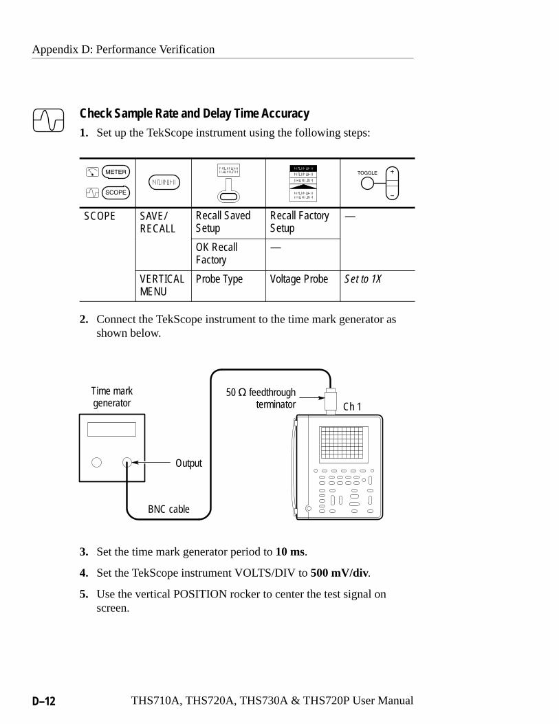
Appendix D: Performance Verification
D–12 THS710A, THS720A, THS730A & THS720P User Manual
Check Sample Rate and Delay Time Accuracy1. Set up the TekScope instrument using the following steps:
SCOPE SAVE/RECALL
Recall SavedSetup
Recall FactorySetup
—
OK Recall Factory
—
VERTICALMENU
Probe Type Voltage Probe Set to 1X
2. Connect the TekScope instrument to the time mark generator asshown below.
Time markgenerator Ch 1
Output
50 � feedthroughterminator
BNC cable
3. Set the time mark generator period to 10 ms.
4. Set the TekScope instrument VOLTS/DIV to 500 mV/div.
5. Use the vertical POSITION rocker to center the test signal onscreen.

Appendix D: Performance Verification
THS710A, THS720A, THS730A & THS720P User Manual D–13
6. Press SET LEVEL TO 50% .
7. Press MAG .
8. Change the TekScope instrument setup using the following steps:
SCOPE HORIZON-TAL MENU
Time Base Delayed RunsAfter Main
—
CLEARMENU
— —
9. Set the delayed time base to 50 ms/div.
10.Change the TekScope instrument setup using the following steps:
SCOPE HORIZON-TAL MENU
Time Base Delayed RunsAfter Main
Set delay timeto 10 ms
CLEARMENU
— — —
11.Set the delayed time base SEC/DIV to 500 ns/div.
12.Check that the rising edge of the marker crosses the centerhorizontal graticule line within ±4 divisions of center graticule.
NOTE. One division of displacement from graticule center corre-sponds to a 50 ppm time base error.

Appendix D: Performance Verification
D–14 THS710A, THS720A, THS730A & THS720P User Manual
Check Channel 1 Edge Trigger Sensitivity1. Set up the TekScope instrument using the following steps:
SCOPE SAVE/RECALL
Recall SavedSetup
Recall FactorySetup
—
OK RecallFactory
—
ACQUIRE Acquire Mode Average Set to 16
TRIGGER Trigger Mode Normal —
MEAS Gating & High-Low Setup
High-LowMethod
Min/Max
SelectMeasrmnt
Ampl* —
OK SelectMeasrmnt
—
* You may need to press Select Page to display this selection.
2. Connect the TekScope instrument to the leveled sine wavegenerator as shown below.
Leveledsine wavegenerator Ch 1
Output
50 � feedthroughterminator
BNC cable

Appendix D: Performance Verification
THS710A, THS720A, THS730A & THS720P User Manual D–15
3. Set the leveled sine wave generator frequency to 200 MHz if youare checking a THS730A or to 100 MHz if you are checking aTHS710A, THS720A or THS720P.
4. Set the TekScope instrument VOLTS/DIV to 500 mV/div.
5. Press MAG .
6. Set the TekScope instrument SEC/DIV to 10 ns/div.
7. Set the leveled sine wave generator output level to approximately50 mVp-p so that the measured amplitude is approximately500 mV. (The measured amplitude can fluctuate around 500 mV.)
8. Press SET LEVEL TO 50% . Adjust TRIGGER LEVEL asnecessary and then check that triggering is stable.
9. Change the TekScope instrument setup using the following steps:
SCOPE TRIGGER Trigger Slope \ (falling edge)
10.Press SET LEVEL TO 50% . Adjust TRIGGER LEVEL asnecessary and then check that triggering is stable.
11.Change the TekScope instrument setup using the following steps:
SCOPE TRIGGER Trigger Slope / (rising edge)
12.Proceed to the next test to check the channel 2 edge triggersensitivity.

Appendix D: Performance Verification
D–16 THS710A, THS720A, THS730A & THS720P User Manual
Check Channel 2 Edge Trigger Sensitivity1. First check the channel 1 edge trigger sensitivity using the
previous test. Then, perform these additional steps to check thechannel 2 edge trigger sensitivity.
SCOPE CH 1 — — —
WAVE-FORMOFF
CH 2
TRIGGER Trigger Source Ch2
MEAS Gating & High-Low Setup
High-LowMethod
Min/Max
SelectMeasrmnt
Ampl* —
OK SelectMeasrmnt
—
* You may need to press Select Page to display this selection.
2. Connect the TekScope instrument to the leveled sine wavegenerator as shown below.
Leveledsine wavegenerator Ch 2
Output
50 � feedthroughterminator
BNC cable

Appendix D: Performance Verification
THS710A, THS720A, THS730A & THS720P User Manual D–17
3. Set the leveled sine wave generator frequency to 200 MHz if youare checking a THS730A or to 100 MHz if you are checking aTHS710A, THS720A or THS720P.
4. Set the TekScope instrument VOLTS/DIV to 500 mV/div.
5. Set the leveled sine wave generator output level to approximately50 mVp-p so that the measured amplitude is approximately500 mV. (The measured amplitude can fluctuate around 500 mV.)
6. Press SET LEVEL TO 50% . Adjust TRIGGER LEVEL asnecessary and then check that triggering is stable.
7. Change the TekScope instrument setup using the following steps:
SCOPE TRIGGER Trigger Slope \ (falling edge)
8. Press SET LEVEL TO 50% . Adjust TRIGGER LEVEL asnecessary and then check that triggering is stable.

Appendix D: Performance Verification
D–18 THS710A, THS720A, THS730A & THS720P User Manual
Check DC Voltage Accuracy1. Set the DC voltage source output level to 0 V.
2. Set up the TekScope instrument using the following steps:
METER — VDC —
3. Connect the TekScope instrument to the DC voltage source asshown below.
+–
DC voltagesource
Banana cables
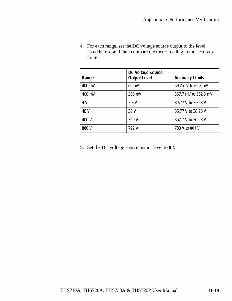
Appendix D: Performance Verification
THS710A, THS720A, THS730A & THS720P User Manual D–19
4. For each range, set the DC voltage source output to the levellisted below, and then compare the meter reading to the accuracylimits.
RangeDC Voltage SourceOutput Level Accuracy Limits
400 mV 60 mV 59.2 mV to 60.8 mV
400 mV 360 mV 357.7 mV to 362.3 mV
4 V 3.6 V 3.577 V to 3.623 V
40 V 36 V 35.77 V to 36.23 V
400 V 360 V 357.7 V to 362.3 V
880 V 792 V 783 V to 801 V
5. Set the DC voltage source output level to 0 V.
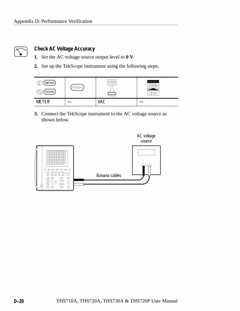
Appendix D: Performance Verification
D–20 THS710A, THS720A, THS730A & THS720P User Manual
Check AC Voltage Accuracy1. Set the AC voltage source output level to 0 V.
2. Set up the TekScope instrument using the following steps:
METER — VAC —
3. Connect the TekScope instrument to the AC voltage source asshown below.
AC voltagesource
Banana cables

Appendix D: Performance Verification
THS710A, THS720A, THS730A & THS720P User Manual D–21
4. Set the AC voltage source output frequency to 500 Hz.
5. For each range, set the AC voltage source output to the levellisted below, and then compare the meter reading to the accuracylimits.
RangeAC Voltage SourceOutput Level Accuracy Limits
400 mV 360 mV 352.3 mV to 367.7 mV
4 V 600 mV 0.583 V to 0.617 V
4 V 3.6 V 3.523 V to 3.677 V
40 V 36 V 35.23 V to 36.77 V
400 V 360 V 352.3 V to 367.7 V
640 V 576 V 559 V to 593 V
6. Set the AC voltage source output level to 0 V.

Appendix D: Performance Verification
D–22 THS710A, THS720A, THS730A & THS720P User Manual
Check Resistance Accuracy1. Set up the TekScope instrument using the following steps:
METER — � —
2. Connect the TekScope instrument to the resistance standard asshown below.
Resistancestandard
Banana cables
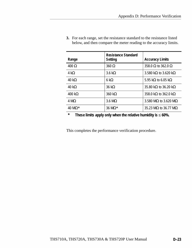
Appendix D: Performance Verification
THS710A, THS720A, THS730A & THS720P User Manual D–23
3. For each range, set the resistance standard to the resistance listedbelow, and then compare the meter reading to the accuracy limits.
RangeResistance StandardSetting Accuracy Limits
400 � 360 � 358.0 � to 362.0 �
4 k� 3.6 k� 3.580 k� to 3.620 k�
40 k� 6 k� 5.95 k� to 6.05 k�
40 k� 36 k� 35.80 k� to 36.20 k�
400 k� 360 k� 358.0 k� to 362.0 k�
4 M� 3.6 M� 3.580 M� to 3.620 M�
40 M�� 36 M�� 35.23 M� to 36.77 M�
* These limits apply only when the relative humidity is ≤ 60%.
This completes the performance verification procedure.

Appendix D: Performance Verification
D–24 THS710A, THS720A, THS730A & THS720P User Manual

THS710A, THS720A, THS730A & THS720P User Manual E–1
Appendix E: General Care and Cleaning
General CareProtect the TekScope instrument from adverse weather conditions.The instrument is not waterproof.
Do not store or leave the instrument where the LCD display will beexposed to direct sunlight for long periods of time.
CAUTION. To avoid damage to the TekScope instrument, do notexpose it to sprays, liquids, or solvents.
CleaningInspect the TekScope instrument as often as operating conditionsrequire. To clean the instrument exterior, perform the followingsteps:
1. Remove loose dust on the outside of the instrument with alint-free cloth. Use care to avoid scratching the clear plasticdisplay filter.
2. Use a soft cloth or paper towel dampened with water to clean theinstrument. You can use a 75% isopropyl alcohol solution formore efficient cleaning.
CAUTION. To avoid damage to the surface of the TekScope instru-ment, do not use any abrasive or chemical cleaning agents.

Appendix E: General Care and Cleaning
E–2 THS710A, THS720A, THS730A & THS720P User Manual

Glossary and Index


THS710A, THS720A, THS730A & THS720P User Manual Glossary–1
Glossary
+/– RockerThe general-purpose rocker button on the front panel that youcan use to set parameters. The specific parameter assigned to the+/– rocker depends on other selections.
AC CouplingA mode that blocks the DC component of a signal but passes thedynamic (AC) component of the signal. Useful for observing anAC signal that is normally riding on a DC signal.
AcquisitionThe process of sampling signals from input channels, digitizingthe samples, processing the results into data points, andassembling the data points into a waveform record. Thewaveform record is stored in memory.
Active CursorThe cursor that moves when you adjust the +/– rocker. The @readout on the display shows the position of the active cursor.
AliasingA false representation of a signal due to insufficient sampling ofhigh frequencies or fast transitions. A condition that occurswhen an oscilloscope digitizes at an effective sampling rate thatis too slow to reproduce the input signal. The waveformdisplayed on the oscilloscope may have a lower frequency thanthe actual input signal.
Glossary
Glossary–2 THS710A, THS720A, THS730A & THS720P User Manual
AttenuationThe degree the amplitude of a signal is reduced when it passesthrough an attenuating device such as a probe or attenuator (theratio of the input measure to the output measure). For example,a 10X probe attenuates, or reduces, the input voltage of a signalby a factor of 10.
Auto Trigger ModeA trigger mode that causes the oscilloscope to automaticallyacquire if it does not detect a triggerable event.
AutorangeA DMM feature that automatically sets the range to theoptimum setting to measure an input signal. Also, an oscillo-scope feature that automatically produces a stable waveform ofusable size. In both cases, autorange continues to change theinstrument settings to track additional signal changes.
Average Acquisition ModeA mode in which the oscilloscope acquires and displays awaveform that is the averaged result of several acquisitions.This reduces the apparent noise. The oscilloscope acquires dataas in the sample mode and then averages it according to aspecified number of averages.
BacklightThe illumination behind the liquid-crystal display.
Bezel ButtonsThe row of buttons below the display that selects items in themenus.
Glossary
THS710A, THS720A, THS730A & THS720P User Manual Glossary–3
Common LeadThe meter lead attached to the reference voltage in a measure-ment application. Because of the isolated channels, the metercommon lead and the scope reference leads do not have to beconnected to the same reference voltage.
ContinuityA test to verify electrical conductivity from one point to another.
CursorsPaired markers that you can use to make measurements betweentwo waveform locations. The oscilloscope displays the values(expressed in volts, time, or degrees) of the position of theactive cursor and the distance between the two cursors.
DC CouplingA mode that passes both AC and DC signal components to thecircuit. Available for both the trigger system and the verticalsystem.
Digital Real Time DigitizingA digitizing technique that samples the input signal with asample frequency of four to five times the oscilloscopebandwidth. Combined with (sinx)/x interpolation, all frequencycomponents of the input up to the bandwidth are accuratelydisplayed.
DigitizingThe process of converting a continuous analog signal such as awaveform to a set of discrete numbers representing theamplitude of the signal at specific points in time.
Glossary
Glossary–4 THS710A, THS720A, THS730A & THS720P User Manual
Diode TestA test to verify polarity and measure the forward voltage drop ofa semiconductor junction.
Displacement Power Factor (DPF)Cosine of the phase angle between fundamental components ofthe voltage and current waveforms.
DisplayThe word used to refer to the screen or the LCD (liquid crystaldisplay).
Edge TriggerTriggering that occurs when the oscilloscope detects the sourcepassing through a specified voltage level in a specified direction(the trigger slope).
Envelope Acquisition ModeA mode in which the oscilloscope acquires and displays awaveform that shows the variation extremes of severalacquisitions.
External TriggerTriggering that occurs when the oscilloscope detects the externalinput signal passing through a specified voltage level in aspecified direction (the trigger slope).
Floating MeasurementsVoltage measurements where the reference voltage is not earthground. The two oscilloscope inputs and the DMM input arecapable of taking independent floating measurements.

Glossary
THS710A, THS720A, THS730A & THS720P User Manual Glossary–5
Ground (GND) CouplingCoupling option that disconnects the input signal from thevertical system.
Hard CopyAn electronic copy of the display in a format useable by aprinter or plotter.
HarmonicsVoltage or current waveforms having frequencies that areinteger multiples of the base (fundamental) frequency. Aperiodic waveform can be described as the sum of its fundamen-tal frequency and the harmonics.
HoldoffA specified amount of time that must elapse after a triggersignal before the trigger circuit will accept another triggersignal. Holdoff helps ensure a stable display.
Horizontal Bar CursorsThe two horizontal bars that you position to measure the voltageparameters of a waveform. The oscilloscope displays the valueof the active (moveable) cursor with respect to ground and thevoltage value between the bars.
Isolated ChannelsThe architecture of the oscilloscope and DMM inputs that allowindependent floating measurements. Each input can have adifferent reference voltage.
Glossary
Glossary–6 THS710A, THS720A, THS730A & THS720P User Manual
MenuA set of labels shown in the display to identify the functions ofthe bezel buttons. The specific menu contents depend on themenu button you press.
Motor TriggerTriggering on the rising or falling edge of a bipolar, motordrivewaveform.
Normal Trigger ModeA mode where the oscilloscope does not acquire a waveformrecord unless a valid trigger event occurs. It waits for a validtrigger event before acquiring waveform data.
Paired CursorsTwo cross-shaped cursors that automatically track the verticalvalues of a waveform when you adjust their horizontal positions.The oscilloscope displays the voltage value and time valuebetween the paired cursors.
PixelA visible point on the display. The display is 320 pixels wide by240 pixels high.
Pop-Up MenuA submenu of a menu. Pop-up menus temporarily occupy partof the waveform display area and present choices associatedwith the menu item selected. You can cycle through the optionsin a pop-up menu by repeatedly pressing the menu buttonunderneath the pop-up.
Glossary
THS710A, THS720A, THS730A & THS720P User Manual Glossary–7
Power Factor (PF)The ratio of true power (watts) to apparent power (volt-amperes).
PretriggerThe specified portion of the waveform record that contains dataacquired before the trigger event.
Pulse TriggerTriggering on events that you can qualify by time. Theoscilloscope triggers when an incoming pulse width meets timecriteria you have defined.
Record LengthThe specified number of samples in a waveform.
Reference LeadThe oscilloscope lead attached to the reference voltage in ameasurement application. Because of the isolated channels, themeter common lead and the scope reference leads do not have tobe connected to the same reference voltage.
Reference WaveformA saved wavefrom selected for display. You can display tworeference waveforms as Ref A and Ref B.
RockerA two-position button on the front panel used to controlfunctions such as volts/division and trigger level.
Glossary
Glossary–8 THS710A, THS720A, THS730A & THS720P User Manual
Roll ModeAn acquisition mode useful at slow horizontal scale settings.Roll mode allows you to view the waveform as it is acquiredpoint-by-point. The waveform appears to roll across the display.
RS-232The serial communication port used to connect to a hard-copydevice, computer, controller, or terminal.
Sample Acquisition ModeA mode in which the oscilloscope creates a record point bysaving the first sample during each acquisition interval. This isthe default mode of the acquisition system.
Sample IntervalThe time interval between successive samples in a time base.For real-time digitizers, the sample interval is the reciprocal ofthe sample rate.
SamplingThe process of capturing an analog input, such as a voltage, at adiscrete point in time and holding it constant so that it can bequantized.
Selected WaveformThe waveform on which all measurements are performed andwhich is affected by vertical position and scale adjustments.

Glossary
THS710A, THS720A, THS730A & THS720P User Manual Glossary–9
Signal Path Compensation (SPC)The ability of the oscilloscope to minimize the electrical offsetsin the vertical, horizontal, and trigger amplifiers caused byambient temperature changes and component aging. You shouldrun SPC when the ambient temperature varies more than 5� Cfrom the last SPC or before performing critical measurements.
Standby (STBY)The off-like state when the instrument in not in use. Somecircuits are active even while the instrument is in the standbystate.
Tek SecureA feature that erases all waveform and setup memory locations(setup memories are replaced with the factory setup). Then itchecks each location to verify erasure. This feature is usefulwhere the oscilloscope is used to gather security-sensitive data.
Time BaseThe set of parameters that let you define the time and horizontalaxis attributes of a waveform record. The time base determineswhen and how long to acquire record points.
Total Harmonic Distortion (THD)The ratio of the waveform harmonic content to the RMS ofeither the fundamental or the input signal, expressed as apercent.

Glossary
Glossary–10 THS710A, THS720A, THS730A & THS720P User Manual
Vertical Bar CursorsThe two vertical bars you position to measure the timeparameter of a waveform record. The oscilloscope displays thevalue of the active (moveable) cursor with respect to trigger andthe time value between the bars.
Video TriggerTriggering on the sync pulse of a composite video signal.
XY FormatA display format that compares the voltage level of twowaveform records point by point. It is useful for studying phaserelationships between two waveforms.
YT FormatThe conventional oscilloscope display format. It shows thevoltage of a waveform record (on the vertical axis) as it variesover time (on the horizontal axis).

THS710A, THS720A, THS730A & THS720P User Manual Index–1
Index
Aaccessories, C–1ACQUIRE button, 2–4, 3–3acquisition
modes, 3–3status, 3–40, 3–49
amplitude measurement, 3–35applications
analyzing serial data communica-tion link, 2–30
detecting glitches, 2–26detecting missing power cycle,
2–42displaying unknown signal, 2–16measuring continuity, 2–19measuring diode junctions, 2–19measuring frequency, 2–20measuring harmonic current,
2–44measuring motor startup current,
2–48measuring power, 2–38, 2–46measuring propagation delay,
2–22measuring resistance, 2–18monitoring power quality, 2–40testing switching transistor, 2–36triggering on external signal,
2–28triggering on missing pulse, 2–24triggering on motor drive wave-
form, 2–52triggering on motor RPM, 2–50triggering on video signal, 2–32
automatic measurements, 3–31
AUTORANGEbutton, 2–6turning off, 3–10turning on, 3–8
average statistic, 3–38averaging, 3–3
Bbacklight, 3–65bandwidth limit, 3–69bar graph, 3–44battery
capacity, 1–6charging, 1–6external charger, C–3low battery indicator, 1–6replacing, 1–5
beep, 3–38burst width measurement, 3–35buttons, using, 2–1, 2–6
Ccleaning, E–1CLEAR MENU button, 2–7connectors, 1–4continuity, 2–19contrast, display, 3–13conventions, vicoupling
trigger, 3–56vertical, 3–69
current probedescription, C–4scale factor, 3–69using, 2–38, 2–50, 3–15
Index
Index–2 THS710A, THS720A, THS730A & THS720P User Manual
CURSOR button, 2–5, 3–11cursors
application example, 2–22readouts, 3–12, 3–41using, 3–11
cycle mean measurement, 3–35cycle RMS measurement, 3–35
Ddata logger
application example, 2–40display, 2–7, 3–42position, 3–43, 3–73saving and recalling, 3–47scroll speed, 3–30zoom, 3–43, 3–73
dB and dBm scale, 3–73delayed time base, 3–29�0 statistic, 3–38diagnostics, 3–67diode test, 2–19DISPLAY button, 2–5, 3–13display contents
meter mode, 3–39scope mode, 3–48
dots, 3–13
Eedge trigger, how to use, 3–56envelope, 3–3external power
connector location, 1–4using, 1–7
external trigger, how to use, 3–56
Ffactory setup
detailed description, B–1recalling, 3–46
fall time measurement, 3–35features
automatic measurements, 2–20cursors, 2–22data logger, 2–40dot accumulate, 2–32isolated channels, 2–12, 2–36overview, 1–1pulse trigger, 2–24, 2–26, 2–50triggers, 3–54waveform math, 2–38
floating measurementsapplication example, 2–36overview, 2–12
frequency measurement, 3–35front panel, 2–1, 2–6functional check, 1–9
Ggraticule, 3–13
HHARD COPY button, 3–22harmonic distortion, calculation
method, 3–17, A–8harmonics
display, 3–17measurements, 3–18menu, 3–16saving and recalling, 3–46setup, 3–16status line, 3–18
Index
THS710A, THS720A, THS730A & THS720P User Manual Index–3
high level measurement, 3–35high voltage, warning, 2–14HOLD button, 3–26holdoff, 3–57HORIZONTAL MENU button,
2–5, 3–27
Iinput protection, A–2, A–10, A–11,
A–12inputs, 1–4intensity, display, 3–13isolated channels
application example, 2–36description, 2–12
Lline trigger, 2–29losing saved information, 1–5low battery indicator, 1–6
MMAG button, 3–28manual conventions, vimath waveform
allowed units, 3–70application example, 2–38functions, 3–70
max measurement, 3–35max statistic, 3–38, 3–44max–min statistic, 3–38mean measurement, 3–35MEAS button, 2–5, 3–31
measurement applicationscontinuity, 2–19data logger, 2–40diode junction, 2–19floating, 2–12, 2–36frequency, 2–20motor current, 2–50phase, 3–12power, 2–38, 2–46propagation delay, 2–22resistance, 2–18
measurement definitionsgated measurements, 3–34harmonics, 3–18, A–8meter mode, 3–38power measurements, 3–20, A–9scope mode, 3–35
measurement gating, 3–34measurement qualifier, 3–53menus
acquire, 2–4, 3–3cursor, 2–5, 3–11display, 2–5, 3–13horizontal, 2–5, 3–27how to use, 2–1measure, 2–5, 3–31meter, 3–39overview, 2–4save/recall, 2–4, 3–45trigger, 2–5, 3–54utility, 2–5, 3–62vertical, 2–5, 3–68
meterdeluxe lead set, C–3lead set, C–1noise reject, 3–73range, 3–43

Index
Index–4 THS710A, THS720A, THS730A & THS720P User Manual
METER button, 3–39meter mode
features, 1–3how to use, 2–9
min measurement, 3–35min statistic, 3–38, 3–44motor trigger, how to use, 3–61
Nnegative duty cycle measurement,
3–36negative overshoot measurement,
3–36negative width measurement, 3–36nonvolatile memory
saving information into, 3–46when replacing battery, 1–5
OON/STBY
button, 2–7using, 1–5, 1–6
overrange indicator, 3–40
PP5102
compensating, 2–10description, C–1, C–3specifications, A–11
P6117compensating, 2–10description, C–1specifications, A–10
peak detect, 3–3peak-to-peak measurement, 3–36performance verification, D–1period measurement, 3–36
phase measurement, 3–12position
data logger, 3–43horizontal, 3–28of reference waveforms, 3–71trigger, 3–29vertical, 3–68
positive duty cycle measurement,3–36
positive overshoot measurement,3–36
positive width measurement, 3–36power measurements, 2–46, 3–20
saving and recalling, 3–46pretrigger, 3–29printing, 3–22probe compensator
location, 1–4using, 2–10
probe descriptionsA605, A610, C–5A621, A622, C–4P5102, C–1, C–3P6117, C–1P6408, C–5
product descriptionaccessories, C–1general, 1–1meter, 1–3oscilloscope, 1–2specifications, A–1
pulse triggerapplication examples, 2–24,
2–26, 2–50how to use, 3–58
Index
THS710A, THS720A, THS730A & THS720P User Manual Index–5
Rreadouts
cursors, 3–12DMM reading, 3–41, 3–50measurements, 3–19, 3–53power measurements, 3–20time base, 3–52trigger, 3–52waveform, 3–19, 3–51
reference lead, 2–14reference waveforms, 3–71Rel �, 3–7reset
data logger, 3–42statistics, 3–38
resistance, 2–18rise time measurement, 3–36RMS measurement, 3–36roll mode, 3–28RS-232
adapters, C–2cable, 3–24, C–2hard copy, 3–22pinout, A–16port location, 1–4setting up, 3–64troubleshooting, 3–64
RUN/STOP button, 3–26
Ssample, 3–3SAVE/RECALL button, 2–4, 3–45saved information, to prevent loss,
1–5SCOPE button, 3–48scope mode
features, 1–2how to use, 2–8
SEC/DIV rockermeter mode, 3–30scope mode, 3–28
selected waveformhow to select, 3–68indicator, 3–50
self test, 3–67SET LEVEL TO 50% button, 2–7setups
factory setup description, B–1saving and recalling, 3–45
signal path compensation, 2–11,3–66
single acquisition sequence, 3–6,3–26
specifications, A–1standby timeout, 3–65statistics
readout location, 3–41resetting, 3–26selecting, 3–37
status, 3–49STBY. See ON/STBY
TT symbol, 3–27, 3–29Tek Secure, 3–63THD, calculation method, 3–17,
A–8tilt stand, 1–8time base, 3–29time-out, 3–65TOGGLE button, 3–11TRIGGER MENU button, 2–5,
3–54trigger position, 3–29trigger status, 3–49
Index
Index–6 THS710A, THS720A, THS730A & THS720P User Manual
triggeringAuto mode, 3–56edge trigger, 3–56external trigger, 3–56motor trigger, 3–61Normal mode, 3–56on AC line, 2–29on glitches, 2–27on missing pulse, 2–24on specific frequency, 2–50on video signal, 2–32pulse trigger, 3–58readout, 3–52setting coupling, 3–56setting holdoff, 3–57setting level, 3–54setting pretrigger, 3–29setting slope, 3–56video trigger, 3–60
UUTILITY button, 2–5, 3–62
Vvectors, 3–13VERTICAL MENU button, 2–5,
3–68video trigger
application examples, 2–32how to use, 3–60sync pulses, 3–60
VOLTS/DIV rockerchannels, 3–69math waveform, 3–70meter mode, 3–43
WWAVEFORM OFF button, 3–68waveforms, saving and recalling,
3–45
XXY display, 3–14
Zzoom, 3–43, 3–73