Embed Size (px)
Citation preview

8/3/2019 TI PRO Montage+Wartung IND GB
http://slidepdf.com/reader/full/ti-pro-montagewartung-ind-gb 1/16
Installation &
Maintenance
Products & Applications
Problem –
Cause –Remedy
Drive solutions with Optibelt
8/3/2019 TI PRO Montage+Wartung IND GB
http://slidepdf.com/reader/full/ti-pro-montagewartung-ind-gb 2/162
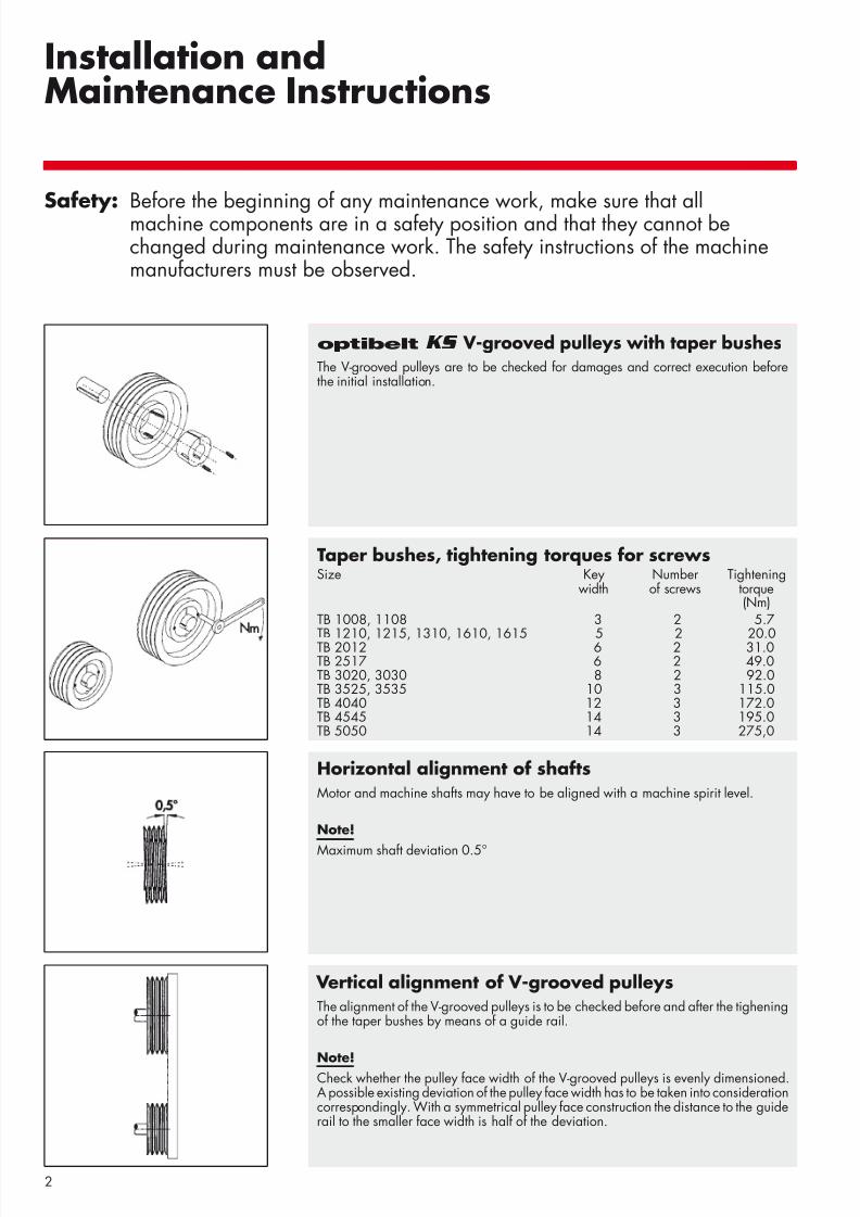
optibelt KS V-grooved pulleys with taper bushesThe V-grooved pulleys are to be checked for damages and correct execution beforethe initial installation.
Horizontal alignment of shaftsMotor and machine shafts may have to be aligned with a machine spirit level.
Note!
Maximum shaft deviation 0.5°
Vertical alignment of V-grooved pulleysThe alignment of the V-grooved pulleys is to be checked before and after the tigheningof the taper bushes by means of a guide rail.
Note!Check whether the pulley face width of the V-grooved pulleys is evenly dimensioned.A possible existing deviation of the pulley face width has to be taken into considerationcorrespondingly. With a symmetrical pulley face construction the distance to the guiderail to the smaller face width is half of the deviation.
Taper bushes, tightening torques for screwsSize Key Number Tightening
width of screws torque(Nm)
TB 1008, 1108 3 2 5.7
TB 1210, 1215, 1310, 1610, 1615 5 2 20.0TB 2012 6 2 31.0TB 2517 6 2 49.0TB 3020, 3030 8 2 92.0TB 3525, 3535 10 3 115.0TB 4040 12 3 172.0TB 4545 14 3 195.0TB 5050 14 3 275,0
Safety: Before the beginning of any maintenance work, make sure that allmachine components are in a safety position and that they cannot bechanged during maintenance work. The safety instructions of the machinemanufacturers must be observed.
Installation andMaintenance Instructions
8/3/2019 TI PRO Montage+Wartung IND GB
http://slidepdf.com/reader/full/ti-pro-montagewartung-ind-gb 3/163
Installation andMaintenance Instructions
Note: These installation and maintenance instructions apply withappropriate modi cations also to Optibelt timing belts and ribbed belts. For details see corresponding technical manuals.
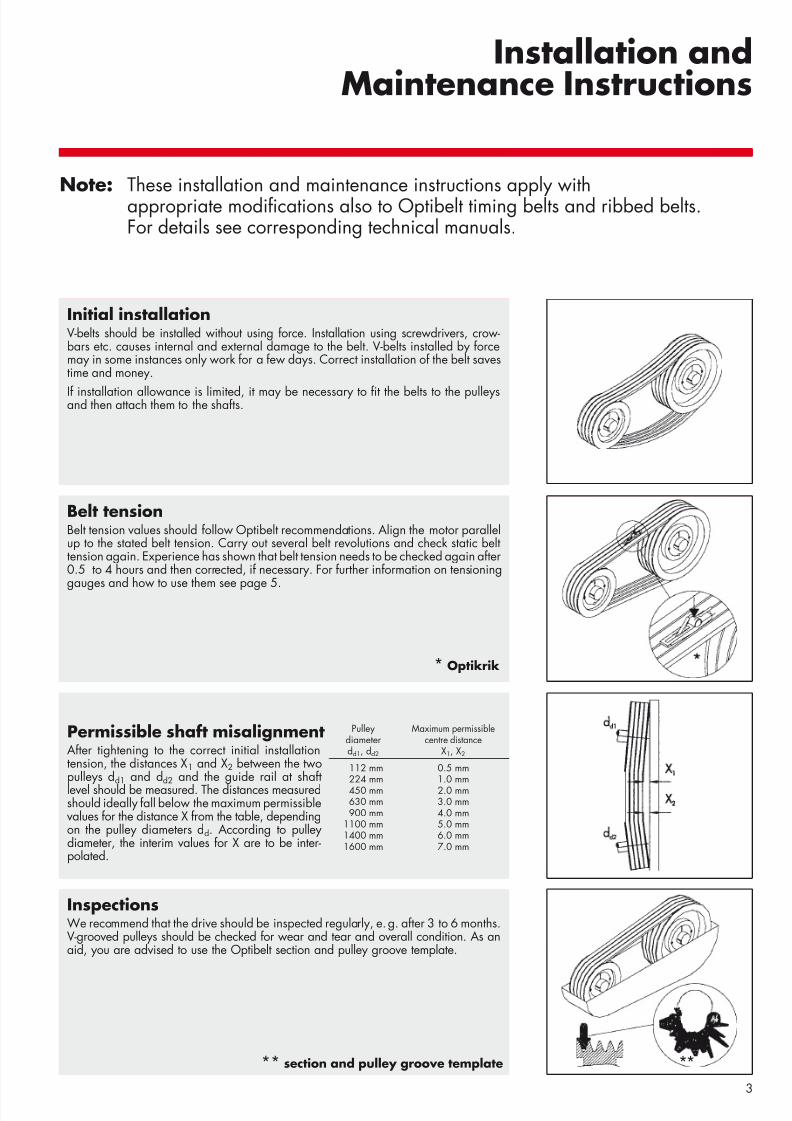
Initial installationV-belts should be installed without using force. Installation using screwdrivers, crow-bars etc. causes internal and external damage to the belt. V-belts installed by forcemay in some instances only work for a few days. Correct installation of the belt savestime and money.
If installation allowance is limited, it may be necessary to t the belts to the pulleysand then attach them to the shafts.
Belt tensionBelt tension values should follow Optibelt recommendations. Align the motor parallelup to the stated belt tension. Carry out several belt revolutions and check static belttension again. Experience has shown that belt tension needs to be checked again after0.5 to 4 hours and then corrected, if necessary. For further information on tensioning
gauges and how to use them see page 5.
InspectionsWe recommend that the drive should be inspected regularly, e. g. after 3 to 6 months.V-grooved pulleys should be checked for wear and tear and overall condition. As anaid, you are advised to use the Optibelt section and pulley groove template.
**** section and pulley groove template
Pulley Maximum permissiblediameter centre distancedd1, dd2 X1, X2
112 mm 0.5 mm224 mm 1.0 mm450 mm 2.0 mm630 mm 3.0 mm900 mm 4.0 mm
1100 mm 5.0 mm1400 mm 6.0 mm1600 mm 7.0 mm
Permissible shaft misalignmentAfter tightening to the correct initial installationtension, the distances X1 and X2 between the twopulleys dd1 and d d2 and the guide rail at shaftlevel should be measured. The distances measuredshould ideally fall below the maximum permissiblevalues for the distance X from the table, dependingon the pulley diameters dd. According to pulleydiameter, the interim values for X are to be inter-polated.
* Optikrik
8/3/2019 TI PRO Montage+Wartung IND GB
http://slidepdf.com/reader/full/ti-pro-montagewartung-ind-gb 4/164
Installation and Maintenance Instructions V-Grooved Pulleys with Taper Bushes
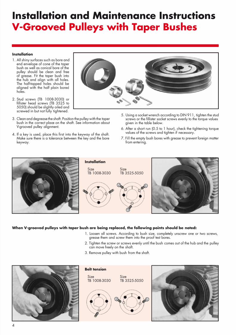
When V-grooved pulleys with taper bush are being replaced, the following points should be noted:
1. Loosen all screws. According to bush size, completely unscrew one or two screws,grease them and screw them into the proof test bores.2. Tighten the screw or screws evenly until the bush comes out of the hub and the pulley
can move freely on the shaft.3. Remove pulley with bush from the shaft.
Installation
Size SizeTB 1008-3030 TB 3525-5050
Belt tension
Size SizeTB 1008-3030 TB 3525-5050
Installation1. All shiny surfaces such as bore and
end envelope of cone of the taperbush as well as conical bore of thepulley should be clean and freeof grease. Fit the taper bush intothe hub and align with all holes.The half-tapped holes should bealigned with the half plain boredholes.
2. Stud screws (TB 1008-3030) orllister head screws (TB 3525 to
5050) should be slightly oiled andscrewed in but not fully tightened.
3. Clean and degrease the shaft. Position the pulley with the taperbush in the correct place on the shaft. See information aboutV-grooved pulley alignment.
4. If a key is used, place this rst into the keyway of the shaft.Make sure there is a tolerance between the key and the borekeyway.
5. Using a socket wrench according to DIN 911, tighten the studscrews or the llister socket screws evenly to the torque valuesgiven in the table below.
6. After a short run (0.5 to 1 hour), check the tightening torquevalues of the screws and tighten if necessary.
7. Fill the empty bush bores with grease to prevent foreign matterfrom entering.
8/3/2019 TI PRO Montage+Wartung IND GB
http://slidepdf.com/reader/full/ti-pro-montagewartung-ind-gb 5/165
Belt Tensionoptibelt Tension Testers
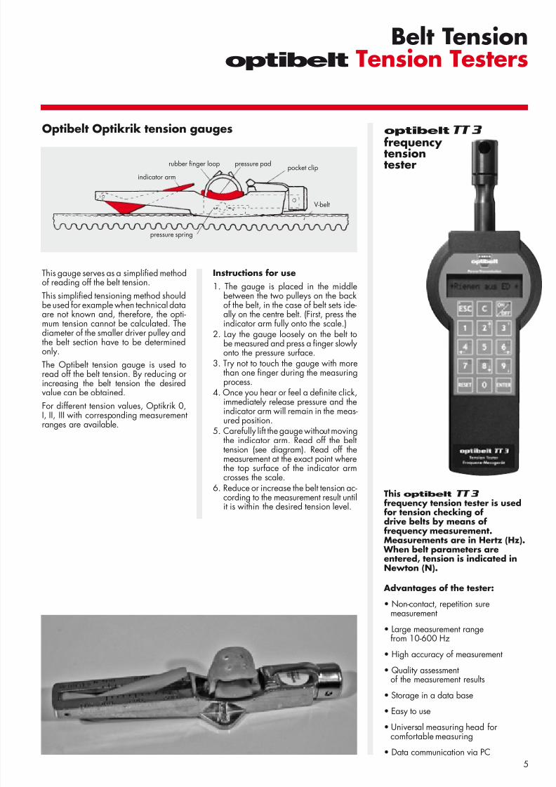
This gauge serves as a simpli ed methodof reading off the belt tension.This simpli ed tensioning method shouldbe used for example when technical dataare not known and, therefore, the opti-mum tension cannot be calculated. Thediameter of the smaller driver pulley andthe belt section have to be determinedonly.The Optibelt tension gauge is used toread off the belt tension. By reducing orincreasing the belt tension the desiredvalue can be obtained.For different tension values, Optikrik 0,I, II, III with corresponding measurementranges are available.
Instructions for use1. The gauge is placed in the middle
between the two pulleys on the backof the belt, in the case of belt sets ide-ally on the centre belt. (First, press theindicator arm fully onto the scale.)
2. Lay the gauge loosely on the belt tobe measured and press a nger slowly onto the pressure surface.
3. Try not to touch the gauge with morethan one nger during the measuringprocess.
4. Once you hear or feel a de nite click,immediately release pressure and the
indicator arm will remain in the meas-ured position.5. Carefully lift the gauge without moving
the indicator arm. Read off the belttension (see diagram). Read off themeasurement at the exact point wherethe top surface of the indicator armcrosses the scale.
6. Reduce or increase the belt tension ac-cording to the measurement result untilit is within the desired tension level.
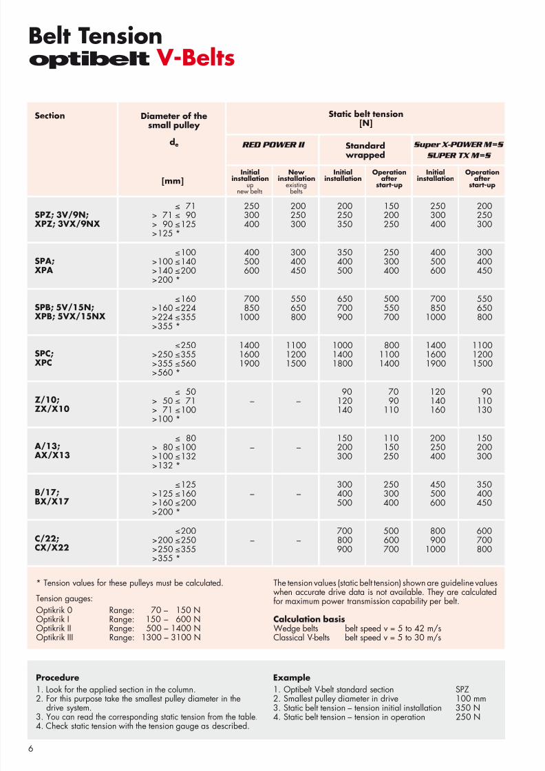
This optibelt TT 3 frequency tension tester is usedfor tension checking ofdrive belts by means offrequency measurement.Measurements are in Hertz (Hz).
When belt parameters areentered, tension is indicated inNewton (N).
Advantages of the tester:
• Non-contact, repetition suremeasurement
• Large measurement rangefrom 10-600 Hz
• High accuracy of measurement
• Quality assessment of the measurement results
• Storage in a data base
• Easy to use
• Universal measuring head for comfortable measuring
• Data communication via PC
optibelt TT 3 frequency tensiontester
Optibelt Optikrik tension gauges
rubber nger loop pocket clippressure pad
V-belt
indicator arm
pressure spring
8/3/2019 TI PRO Montage+Wartung IND GB
http://slidepdf.com/reader/full/ti-pro-montagewartung-ind-gb 6/166
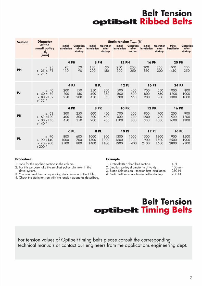
Belt Tensionoptibelt V-Belts
noitceS noisnettlebcitatS]N[
]mm[
;N9/ V3;ZPS XN9/ X V3;ZP X
; APS AP X
;N51/ V5;BPS XN51/ X V5;BP X
;CPSCP X
;01/Z01 X/ XZ
;31/ A31 X/ X A
;71/B71 X/ XB
;22/C 22 X/ XC
≤ 71 250 200 200 150 250 200> 71 ≤ 90 300 250 250 200 300 250> 90 ≤ 125 400 300 350 250 400 300> 125 *
≤ 100 400 300 350 250 400 300> 100 ≤ 140 500 400 400 300 500 400> 140 ≤ 200 600 450 500 400 600 450> 200 *
≤ 160 700 550 650 500 700 550> 160 ≤ 224 850 650 700 550 850 650> 224 ≤ 355 1000 800 900 700 1000 800> 355 *
≤ 250 1400 1100 1000 800 1400 1100> 250 ≤ 355 1600 1200 1400 1100 1600 1200> 355 ≤ 560 1900 1500 1800 1400 1900 1500> 560 *
≤ 50 90 70 120 90
> 50≤
71 – – 120 90 140 110> 71 ≤ 100 140 110 160 130> 100 *
≤ 80 150 110 200 150> 80 ≤ 100 – – 200 150 250 200> 100 ≤ 132 300 250 400 300> 132 *
≤ 125 300 250 450 350> 125 ≤ 160 – – 400 300 500 400> 160 ≤ 200 500 400 600 450> 200 *
≤ 200 700 500 800 600> 200 ≤ 250 – – 800 600 900 700> 250 ≤ 355 900 700 1000 800> 355 *
* Tension values for these pulleys must be calculated.
Tension gauges:Optikrik 0 Range: 70 – 150 N Optikrik I Range: 150 – 600 N Optikrik II Range: 500 – 1400 N Optikrik III Range: 1300 – 3100 N
The tension values (static belt tension) shown are guideline valueswhen accurate drive data is not available. They are calculatedfor maximum power transmission capability per belt.
Calculation basisWedge belts belt speed v = 5 to 42 m/sClassical V-belts belt speed v = 5 to 30 m/s
RED POWER II Super X-POWER M=S
SUPER TX M=S
Procedure1. Look for the applied section in the column.2. For this purpose take the smallest pulley diameter in the
drive system.3. You can read the corresponding static tension from the table.4. Check static tension with the tension gauge as described.
Example1. Optibelt V-belt standard section SPZ2. Smallest pulley diameter in drive 100 mm3. Static belt tension – tension initial installation 350 N4. Static belt tension – tension in operation 250 N
Standard wrapped
Initialinstallation
upnew belts
New installation
existingbelts
Initialinstallation
Operationafter
start-up
Initialinstallation
Operationafter
start-up
Diameter of thesmall pulley
d e
8/3/2019 TI PRO Montage+Wartung IND GB
http://slidepdf.com/reader/full/ti-pro-montagewartung-ind-gb 7/167
noitceS retemaiDehtfo
yellupllams]mm[
HP
HP4 HP8 HP21 HP61 HP02
JP
JP4 JP8 JP21 JP61 JP42
KP
KP4 KP8 KP01 KP21 KP61
LP
LP6 LP8 LP01 LP21 LP61
Belt Tensionoptibelt Ribbed Belts
Static tension T max [N]
≤ 25 90 70 150 130 250 200 300 250 400 300 > 25 ≤ 71 110 90 200 150 300 250 350 300 450 350 > 71 *
≤ 40 200 150 350 300 500 400 700 550 1000 800 > 40 ≤ 80 200 150 400 350 600 500 800 650 1200 1000 > 80 ≤ 132 250 200 450 350 700 550 900 700 1300 1000 > 132 *
≤ 63 300 250 600 450 700 600 900 700 1200 900 > 63 ≤ 100 400 300 800 600 1000 700 1200 900 1500 1200 > 100 ≤ 140 450 350 900 700 1100 800 1300 1000 1600 1300 > 140 *
≤ 90 800 600 1000 800 1300 1000 1500 1200 1900 1500> 90 ≤ 140 1000 700 1300 1000 1600 1300 1900 1500 2500 1900> 140 ≤ 200 1100 800 1400 1100 1900 1400 2100 1600 2800 2100> 200 *
d e
For tension values of Optibelt timing belts please consult the correspondingtechnical manuals or contact our engineers from the applications engineering dept.
Procedure1. Look for the applied section in the column.2. For this purpose take the smallest pulley diameter in the
drive system.3. You can read the corresponding static tension in the table.4. Check the static tension with the tension gauge as described.
Example1. Optibelt RB ribbed belt section 4 PJ2. Smallest pulley diameter in drive db 100 mm3. Static belt tension – tension rst installation 250 N4. Static belt tension – tension after start-up 200 N
Belt Tensionoptibelt Timing Belts
Initial Operation Initial Operation Initial Operation Initial Operation Initial Operationinstallation after installation after installation after installation after installation after
start-up start-up start-up start-up start-up
8/3/2019 TI PRO Montage+Wartung IND GB
http://slidepdf.com/reader/full/ti-pro-montagewartung-ind-gb 8/168
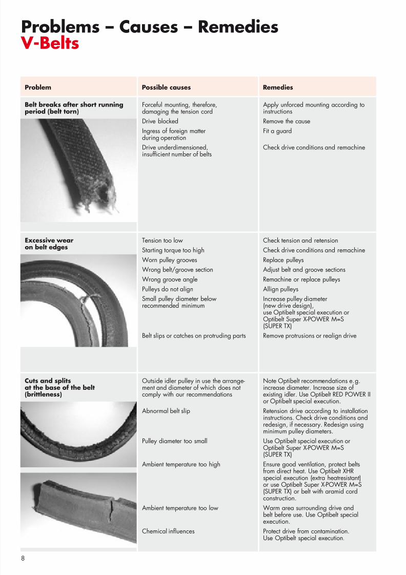
Problems – Causes – Remedies V-Belts
Problem Possible causes Remedies
Belt breaks after short runningperiod (belt torn)
Cuts and splitsat the base of the belt(brittleness)
Note Optibelt recommendations e.g.increase diameter. Increase size of existing idler. Use Optibelt RED POWER II
or Optibelt special execution.Retension drive according to installationinstructions. Check drive conditions andredesign, if necessary. Redesign usingminimum pulley diameters.Use Optibelt special execution or Optibelt Super X-POWER M=S (SUPER TX)Ensure good ventilation, protect beltsfrom direct heat. Use Optibelt XHRspecial execution (extra heatresistant)or use Optibelt Super X-POWER M=S (SUPER TX) or belt with aramid cordconstruction.Warm area surrounding drive andbelt before use. Use Optibelt specialexecution.Protect drive from contamination.Use Optibelt special execution.
Outside idler pulley in use the arrange-ment and diameter of which does notcomply with our recommendations
Abnormal belt slip
Pulley diameter too small
Ambient temperature too high
Ambient temperature too low
Chemical in uences
Forceful mounting, therefore,damaging the tension cordDrive blockedIngress of foreign matterduring operationDrive underdimensioned,insuf cient number of belts
Apply unforced mounting according toinstructionsRemove the causeFit a guard
Check drive conditions and remachine
Check tension and retensionCheck drive conditions and remachineReplace pulleysAdjust belt and groove sectionsRemachine or replace pulleysAllign pulleys
Increase pulley diameter(new drive design),use Optibelt special execution or Optibelt Super X-POWER M=S(SUPER TX)Remove protrusions or realign drive
Tension too lowStarting torque too highWorn pulley groovesWrong belt/groove sectionWrong groove anglePulleys do not align
Small pulley diameter belowrecommended minimum
Belt slips or catches on protruding parts
Excessive wearon belt edges
8/3/2019 TI PRO Montage+Wartung IND GB
http://slidepdf.com/reader/full/ti-pro-montagewartung-ind-gb 9/169
Problems – Causes – Remedies V-Belts
Severe belt vibration Drive overloaded (underdimensioned)Centre distance far larger thanrecommendations
High shock loads
Belt tension too lowUnbalanced V-grooved pulleys
Check drive conditions and redesignReduce shaft centre distance; use insideidler pulley on the drive slack side.Use Optibelt kraftbands.Use Optibelt kraftbands.Use inside idler pulley.Use Optibelt special execution.Correct tensionBalance pulleys
Belts cannotbe retensioned
Allowance of centre distance too low
Excessive belt stretching, due tounderdimensioned (and overloaded) driveWrong belt length
Modify drive to allow more take-upaccording to Optibelt recommendationsRecalculate drive design and modify
Use shorter belt length
Problem Possible causes Remedies
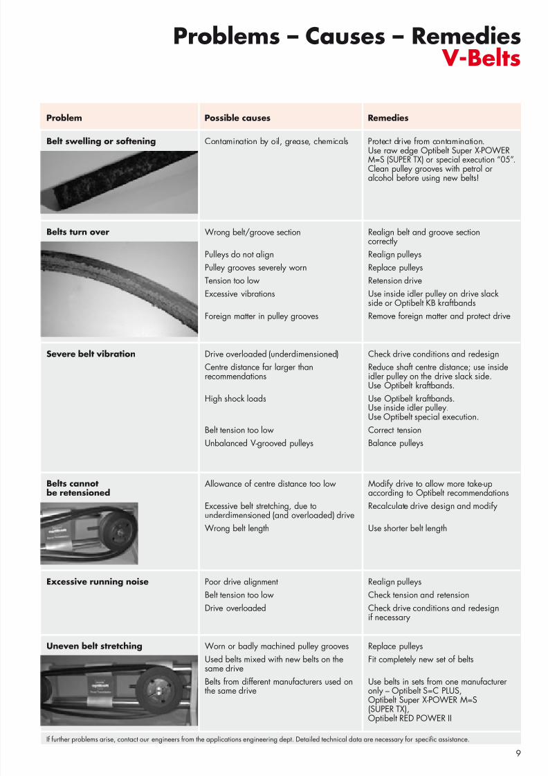
Belt swelling or softening Contamination by oil, grease, chemicals Protect drive from contamination.Use raw edge Optibelt Super X-POWERM=S (SUPER TX) or special execution “05”. Clean pulley grooves with petrol oralcohol before using new belts!
Belts turn over Wrong belt/groove section
Pulleys do not align
Pulley grooves severely wornTension too lowExcessive vibrations
Foreign matter in pulley grooves
Realign belt and groove sectioncorrectlyRealign pulleys
Replace pulleysRetension driveUse inside idler pulley on drive slackside or Optibelt KB kraftbandsRemove foreign matter and protect drive
Excessive running noise Poor drive alignmentBelt tension too lowDrive overloaded
Realign pulleysCheck tension and retensionCheck drive conditions and redesignif necessary
Uneven belt stretching Worn or badly machined pulley groovesUsed belts mixed with new belts on thesame drive
Belts from different manufacturers used onthe same drive
Replace pulleysFit completely new set of belts
Use belts in sets from one manufactureronly – Optibelt S=C PLUS, Optibelt Super X-POWER M=S (SUPER TX),Optibelt RED POWER II
If further problems arise, contact our engineers from the applications engineering dept. Detailed technical data are necessary for speci c assistance.
8/3/2019 TI PRO Montage+Wartung IND GB
http://slidepdf.com/reader/full/ti-pro-montagewartung-ind-gb 10/1610
Problem Possible causes Remedies
Problems – Causes – RemediesRibbed Belts
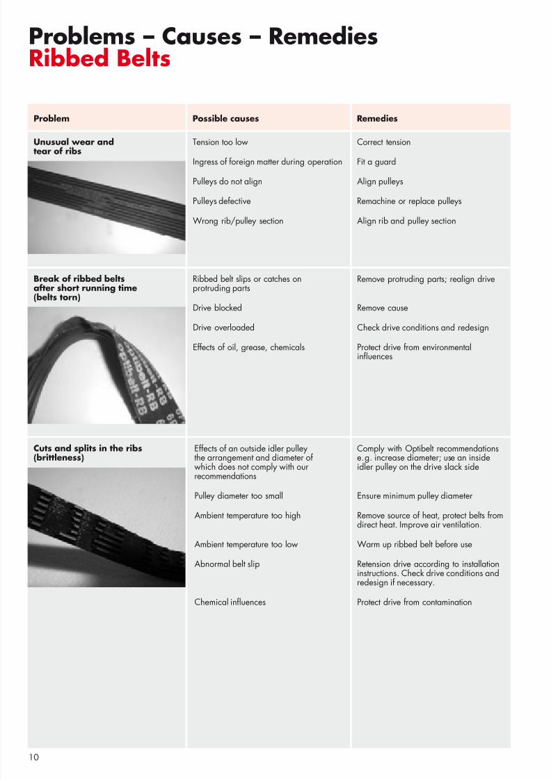
Unusual wear andtear of ribs
Tension too low
Ingress of foreign matter during operation
Pulleys do not align
Pulleys defective
Wrong rib/pulley section
Correct tension
Fit a guard
Align pulleys
Remachine or replace pulleys
Align rib and pulley section
Break of ribbed beltsafter short running time(belts torn)
Ribbed belt slips or catches onprotruding parts
Drive blocked
Drive overloaded
Effects of oil, grease, chemicals
Remove protruding parts; realign drive
Remove cause
Check drive conditions and redesign
Protect drive from environmentalin uences
Cuts and splits in the ribs(brittleness)
Comply with Optibelt recommendationse.g. increase diameter; use an insideidler pulley on the drive slack side
Ensure minimum pulley diameter
Remove source of heat, protect belts fromdirect heat. Improve air ventilation.
Warm up ribbed belt before useRetension drive according to installationinstructions. Check drive conditions andredesign if necessary.
Protect drive from contamination
Effects of an outside idler pulleythe arrangement and diameter of which does not comply with ourrecommendations
Pulley diameter too small
Ambient temperature too high
Ambient temperature too lowAbnormal belt slip
Chemical in uences
8/3/2019 TI PRO Montage+Wartung IND GB
http://slidepdf.com/reader/full/ti-pro-montagewartung-ind-gb 11/1611
Problem Possible causes Remedies
Problems – Causes – RemediesRibbed Belts
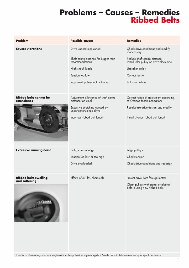
Severe vibrations Check drive conditions and modifyif necessary
Reduce shaft centre distance.Install idler pulley on drive slack side.
Use idler pulley
Correct tension
Balance pulleys
Drive underdimensioned
Shaft centre distance far bigger thanrecommendations
High shock loads
Tension too low
V-grooved pulleys not balanced
Correct range of adjustment accordingto Optibelt recommendations
Recalculate drive design and modify
Install shorter ribbed belt length
Adjustment allowance of shaft centredistance too small
Excessive stretching caused byunderdimensioned drive
Incorrect ribbed belt length
Ribbed belts cannot beretensioned
Excessive running noise Pulleys do not align
Tension too low or too high
Drive overloaded
Align pulleys
Check tension
Check drive conditions and redesign
Ribbed belts swellingand softening
Effects of oil, fat, chemicals Protect drive from foreign matter
Clean pulleys with petrol or alcoholbefore using new ribbed belts
If further problems arise, contact our engineers from the applications engineering dept. Detailed technical data are necessary for speci c assistance.
8/3/2019 TI PRO Montage+Wartung IND GB
http://slidepdf.com/reader/full/ti-pro-montagewartung-ind-gb 12/1612
Problem Possible causes Remedies
Problems – Causes – RemediesTiming Belts
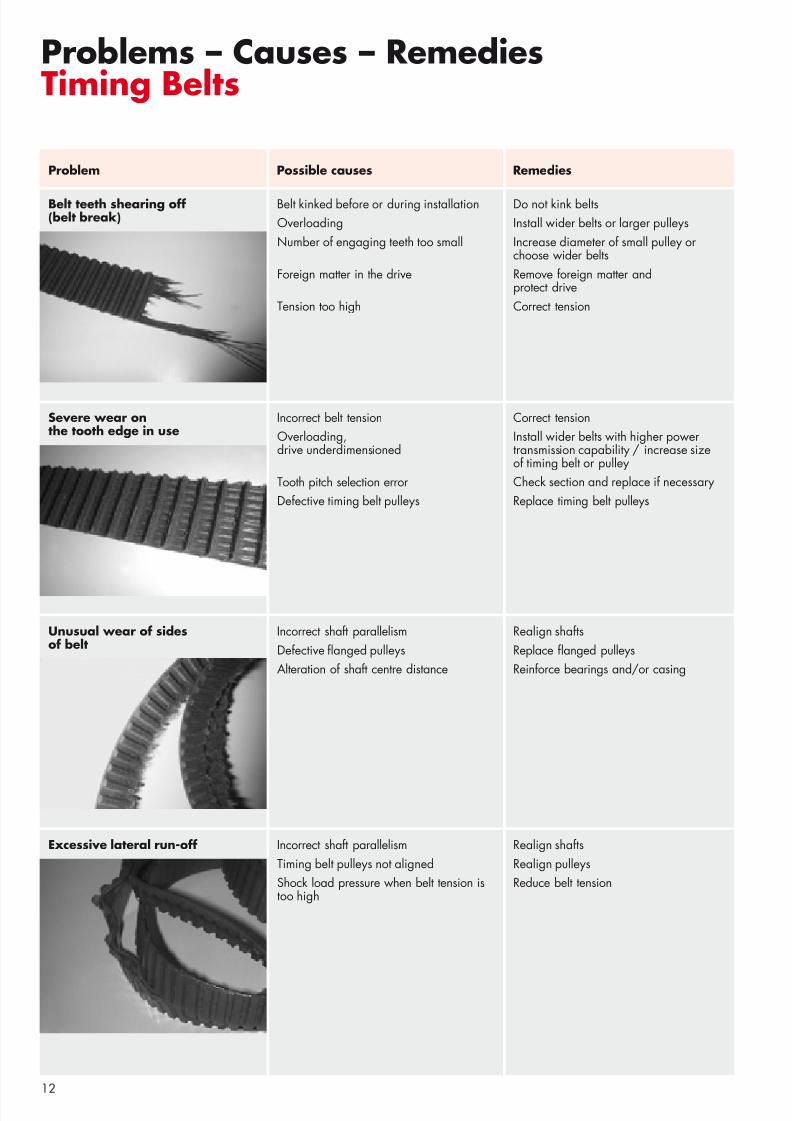
Belt kinked before or during installationOverloadingNumber of engaging teeth too small
Foreign matter in the drive
Tension too high
Do not kink beltsInstall wider belts or larger pulleysIncrease diameter of small pulley orchoose wider beltsRemove foreign matter andprotect driveCorrect tension
Severe wear onthe tooth edge in use
Incorrect belt tensionOverloading, drive underdimensioned
Tooth pitch selection errorDefective timing belt pulleys
Correct tensionInstall wider belts with higher powertransmission capability / increase sizeof timing belt or pulleyCheck section and replace if necessaryReplace timing belt pulleys
Unusual wear of sidesof belt
Incorrect shaft parallelismDefective anged pulleysAlteration of shaft centre distance
Realign shaftsReplace anged pulleysReinforce bearings and/or casing
Excessive lateral run-off Incorrect shaft parallelismTiming belt pulleys not alignedShock load pressure when belt tension istoo high
Realign shaftsRealign pulleysReduce belt tension
Belt teeth shearing off(belt break)
8/3/2019 TI PRO Montage+Wartung IND GB
http://slidepdf.com/reader/full/ti-pro-montagewartung-ind-gb 13/1613
Problem Possible causes Remedies
Problems – Causes – RemediesTiming Belts
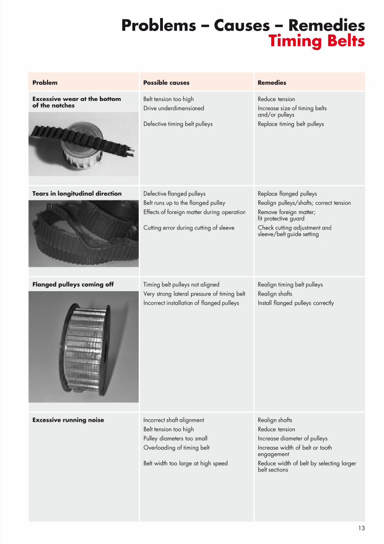
Excessive wear at the bottomof the notches
Belt tension too highDrive underdimensioned
Defective timing belt pulleys
Reduce tensionIncrease size of timing beltsand/or pulleysReplace timing belt pulleys
Tears in longitudinal direction Defective anged pulleysBelt runs up to the anged pulleyEffects of foreign matter during operation
Cutting error during cutting of sleeve
Replace anged pulleysRealign pulleys/shafts; correct tensionRemove foreign matter;
t protective guardCheck cutting adjustment andsleeve/belt guide setting
Flanged pulleys coming off Timing belt pulleys not alignedVery strong lateral pressure of timing beltIncorrect installation of anged pulleys
Realign timing belt pulleysRealign shaftsInstall anged pulleys correctly
Excessive running noise Incorrect shaft alignmentBelt tension too highPulley diameters too smallOverloading of timing belt
Belt width too large at high speed
Realign shaftsReduce tensionIncrease diameter of pulleysIncrease width of belt or toothengagementReduce width of belt by selecting largerbelt sections
8/3/2019 TI PRO Montage+Wartung IND GB
http://slidepdf.com/reader/full/ti-pro-montagewartung-ind-gb 14/1614
Problem Possible causes Remedies
Problems – Causes – RemediesTiming Belts
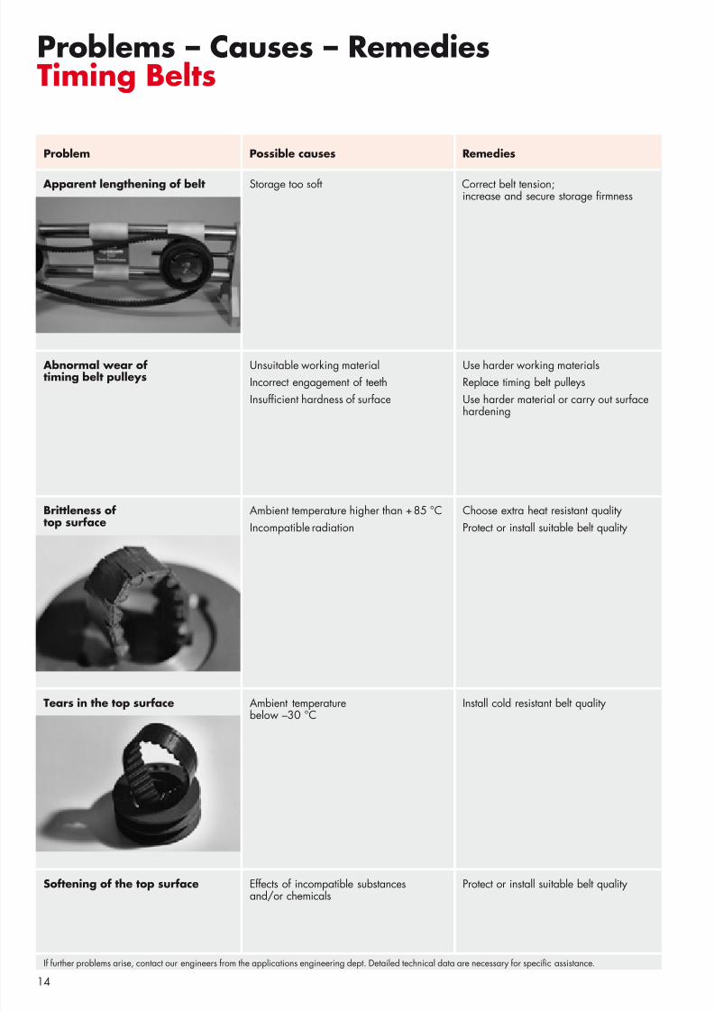
Abnormal wear oftiming belt pulleys
Unsuitable working materialIncorrect engagement of teethInsuf cient hardness of surface
Use harder working materialsReplace timing belt pulleysUse harder material or carry out surfacehardening
Brittleness oftop surface
Ambient temperature higher than +85 °C
Incompatible radiation
Choose extra heat resistant quality
Protect or install suitable belt quality
Tears in the top surface Ambient temperaturebelow –30 °C Install cold resistant belt quality
Softening of the top surface Effects of incompatible substancesand/or chemicals Protect or install suitable belt quality
Apparent lengthening of belt Storage too soft Correct belt tension;increase and secure storage rmness
If further problems arise, contact our engineers from the applications engineering dept. Detailed technical data are necessary for speci c assistance.
8/3/2019 TI PRO Montage+Wartung IND GB
http://slidepdf.com/reader/full/ti-pro-montagewartung-ind-gb 15/1615
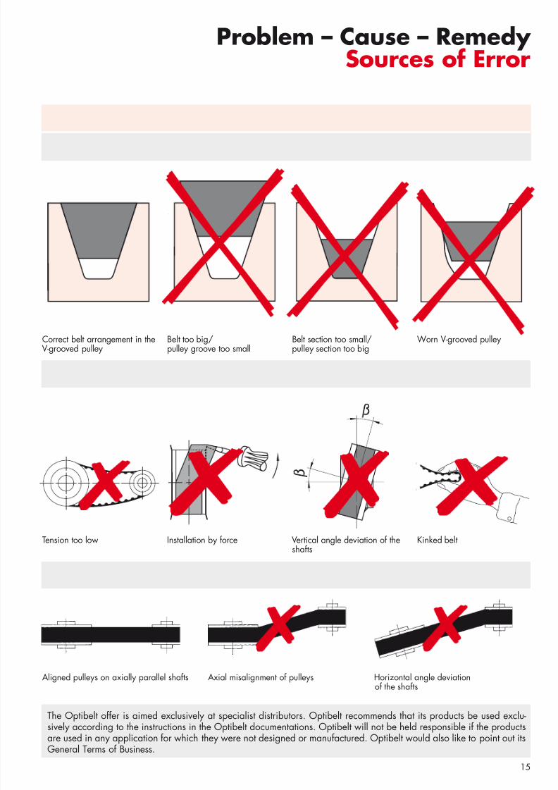
Problem – Cause – Remedy Sources of Error
Correct belt arrangement in theV-grooved pulley
Belt too big/pulley groove too small
Tension too low Installation by force Vertical angle deviation of the
shafts
Kinked belt
Aligned pulleys on axially parallel shafts Axial misalignment of pulleys Horizontal angle deviationof the shafts
The Optibelt offer is aimed exclusively at specialist distributors. Optibelt recommends that its products be used exclu-sively according to the instructions in the Optibelt documentations. Optibelt will not be held responsible if the productsare used in any application for which they were not designed or manufactured. Optibelt would also like to point out itsGeneral Terms of Business.
Belt section too small/pulley section too big
Worn V-grooved pulley
•
• • • • • •
•
•
•
•
•
•
• •
•
•
•
•
••
•
•
8/3/2019 TI PRO Montage+Wartung IND GB
http://slidepdf.com/reader/full/ti-pro-montagewartung-ind-gb 16/16
Optibelt GmbHP.O. Box 10 0132 • 37669 Höxter/Germany • Tel. +49 (0) 52 71 - 6 21 • Fax +49 (0) 52 71 - 976200
Installation, Maintenance and Storage
r n t z O p
t i b e l t
G r o u p
3 1 5 0 6 3 / 0 1 1 0 H u x
Drives with Optibelt V-belts that havebeen correctly installed in terms of geometry and performance guaranteehigh operational safety and maximumdurability.Practice has shown that unsatisfactoryservice life is often caused by installa-tion and maintenance errors. In orderto prevent these, we recommend that
you carefully follow the below mentionedinstallation and maintenance instructions:
• Safety Before the beginning of any mainte-nance work, make sure that all ma-chine components are in a safety posi-tion and that they cannot be changedduring maintenance work. The safetyinstructions of the machine manufactur-ers must be observed.
• PulleysThe grooves must be produced accord-ing to standard and must be clean.
• AlignmentShafts and pulleys must be correctlyaligned before installation.We recommend that the maximumdeviation of the pulley alignment shouldnot exceed 1/ 2°.
• Multi-groove drivesV-belts for multi-groove drives mustusually be measured in sets. Thebelt set tolerance according to thevalid standard should be noted here.Optibelt S=C PLUS and OptibeltSuper X-POWER M=S (SUPER TX)V-belts, however, can be combined intosets without measuring.
• Installation of the V-beltsBefore installation, the shaft centredistance is to be reduced so that thebelts can be placed in the grooveswithout force. Forced installationusing crow-bars, screwdrivers etc. is notpermitted under any circum-stances, asthis damages – often not visible – thehigh-quality, low-stretch tension cord orthe cover fabric.
• Belt tensionAfter the calculated shaft loading hasbeen obtained, the tension of the beltsshould be checked. We recommend
that you use our Optibelt tension gaug-es for this purpose. The drive shouldbe observed during the rst hours of
operation, and experience shows thatit will need to be retensioned afterrunning for a period from 0.5 to 4 hoursunder full load. This restores tension tothe original level.
• Idler pulleys / guide pulleysIdler pulleys and guide pulleys are tobe avoided. If they have to be used, therecommendations of our manual mustbe followed.
• MaintenanceWe recommend regular checks of theV-belt drives. This includes checking the
tension and, if necessary, correcting it.If in the case of multi-groove drives oneor more V-belts fail, a new V-belt setmust be mounted. V-belts from differentmanufacturers must not be combined toform a belt set. Before mounting newV-belts, the condition of the V-belt pul-leys must be checked.Optibelt V-belts do not require anyspecial care. Belt wax and belt sprayshould not be used.
• Storage – generalCorrectly stored V-belts maintain theirquality and properties over a periodof several years (also see DIN 7716).In unfavourable storage conditions andwhen incorrectly treated, most rubberproducts change their physical prop-erties. Such changes can be causedfor example by the effects of oxygen,ozone, extreme temperatures, light,dampness or solvents.
• Store-roomThe store-room should be dry and freeof dust.V-belts should not be stored togetherwith chemicals, solvents, fuel, lubri-cants, acids etc.
• TemperatureThe recommended storage tempera-ture should be +15 °C to + 25 °C.Lower temperatures do not generallycause damage to V-belts. However,as they become very stiff as a result of cold, they should be brought up to atemperature of about +20 °C beforeoperation. This will help to preventbreaks and tears.Radiators and radiator pipes shouldbe screened. The distance between theradiators and the stored goods must beat least 1 m.
• LightV-belts should be protected from light,especially from direct sunlight and fromstrong arti cial light with a high ultra-violet content (ozone formation), e.g.naked neon tubes. The ideal form of lighting is with normal light bulbs.
• OzoneTo counteract the harmful effects of ozone, the store-rooms must not con-tain any ozone-producing items e.g.
uorescent light sources, mercury vapour lamps, high-voltage electrical equipment etc. Combustion gases
and vapours that can cause theproduction of ozone as a result of photo-chemical processes should beavoided or eliminated.
• DampnessDamp store rooms are unsuitable.Efforts should be made to ensure thatno condensation occurs. The relativeair humidity should ideally be under65%.
• StorageV-belts should be stored without ten-sion, i.e. without pulling, pressure orother deformations, as tension andpermanent deformations can lead toformation of cracks.If V-belts are placed on top of eachother, it is advisable not to exceed astacking height of 300 mm in order toavoid permanent deformations. If forreasons of space the belts are sus-pended, the diameter of the mandrelshould be at least 10 times the heightof the belt.
In the case ofoptibelt S=C pluS,optibelt RED pOWER II andoptibelt S er X-pOWER M=S (SupER TX) there is no need to storein sets as these belts can becombined into sets withoutmeasuring.
• CleaningCleaning of dirty V-belts should bedone with a glycerine-spirit mixturein the proportion of 1 : 10. Petrol,benzene, turpentine etc. should notbe used. Sharp-edged objects, wirebrushes, sandpaper etc. should not beused under any circumstances as thiscan cause mechanical damage to theV-belts.