Embed Size (px)
Citation preview

Technical InformationTI057D/06/en50099325
Ultrasonic Flow Measuring SystemPROline prosonic flow 90/93 W/U/C
Flow Rate Measuring for Standard Applicationswith Drinking Water, Wastewaterand Process Water
Your benefitsW and U Clamp On version:• Non-invasive measurement from
outside• Easy and low-cost mounting• Large nominal diameter range
– U Clamp On: DN 15...100– W Clamp On: DN 50...4000
W Insertion version:• Short inlet runs with dual path
measurement• DN 200...4000 single path
measurement• DN 400...4000 dual path measurement
C Inline version:• High accuracy• Traceably calibrated• DN 300...2000
Transmitter:• 90 and 93 in protected wall-mount
housing in IP 67• “Quick Setup” menus for easy
commissioning• Interfaces:
– HART standard (90/93)– PROFIBUS PA (90/93)– PROFIBUS DP (93)– FOUNDATION Fieldbus (93)
ApplicationThe W, U and C sensors are perfectly suited to bidirectional measurement of pure or slightly contaminated liquids with a gas content < 1 % or a solids content < 5 %.
Application examples:• Ultrapure water with low conductivity,
drinking water, wastewater etc.
W and U Clamp On version:• Ideal for retrofitting, installation
possible without interrupting process• Suitable for all acoustically
transmissive pipes and homogeneous fluids.
W Insertion version:• For use on weldable pipes, also with
lining• For applications with short inlet runs.
C Inline version:• Where guaranteed and verifiable
accuracy is demanded.• Where traceability is a requirement.
PROline Prosonic Flow 90/93 W/U/C
2 Endress+Hauser
Function and system design
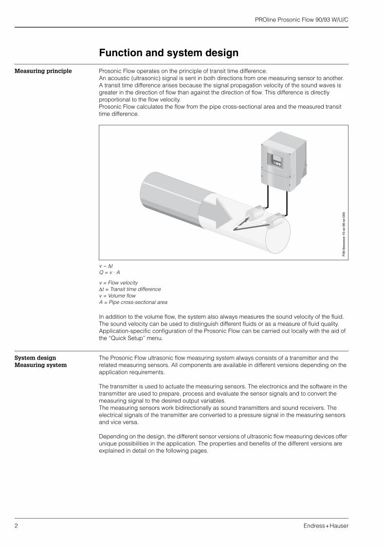
Measuring principle Prosonic Flow operates on the principle of transit time difference.An acoustic (ultrasonic) signal is sent in both directions from one measuring sensor to another.A transit time difference arises because the signal propagation velocity of the sound waves is greater in the direction of flow than against the direction of flow. This difference is directly proportional to the flow velocity.Prosonic Flow calculates the flow from the pipe cross-sectional area and the measured transit time difference.
v ~ ∆tQ = v · A
v = Flow velocity∆t = Transit time differencev = Volume flowA = Pipe cross-sectional area
In addition to the volume flow, the system also always measures the sound velocity of the fluid. The sound velocity can be used to distinguish different fluids or as a measure of fluid quality. Application-specific configuration of the Prosonic Flow can be carried out locally with the aid of the “Quick Setup” menu.
System design Measuring system
The Prosonic Flow ultrasonic flow measuring system always consists of a transmitter and the related measuring sensors. All components are available in different versions depending on the application requirements.
The transmitter is used to actuate the measuring sensors. The electronics and the software in the transmitter are used to prepare, process and evaluate the sensor signals and to convert the measuring signal to the desired output variables.The measuring sensors work bidirectionally as sound transmitters and sound receivers. The electrical signals of the transmitter are converted to a pressure signal in the measuring sensors and vice versa.
Depending on the design, the different sensor versions of ultrasonic flow measuring devices offer unique possibilities in the application. The properties and benefits of the different versions are explained in detail on the following pages.
F06
-9xx
xxxx
x-15
-xx-
06-x
x-00
0

PROline Prosonic Flow 90/93 W/U/C
Endress+Hauser 3
System design Clamp On sensors
PROline Prosonic Flow W and U
Sensor arrangementThe transmitter offers a number of options between 1 and 4 traverses for the type of installation. Please note that the signal strength is reduced with each additional reflection point in the pipe. (Example: 2 traverses = 1 reflection point)To achieve the best signal quality possible, choose the least number of traverses required for a sufficient transit time difference.
1 = 1 traverse, 2 = 2 traverses, 4 = 4 traverses
Recommendations:Due to their design and properties, the Prosonic Flow sensors are particularly suited to certain nominal diameter ranges and pipe wall thicknesses. For this reason, various sensor types are offered for Prosonic Flow W and U for these different applications.Recommendations for sensor installation can be found in the following table.
* see note below
! Note:• The installation of Clamp On sensors is principally recommended in the 2 traverse type of
installation. This type of installation allows the easiest and most comfortable type of mounting and means that a system can also be mounted even if the pipe can only be accessed from one side.
• If the pipe nominal diameter is small (DN 60 and smaller), the sensor spacing with Prosonic Flow W can be too small for an installation with 2 traverses. In this case, the 4 traverse type of installation must be used. In all other instances, the 2 traverse configuration is the preferred method.
• The use of Prosonic Flow W sensors DN 100...4000 is principally recommended for pipes with a wall thickness >4 mm, pipes made of composites such as GRP, pipes with lining, even for nominal diameters < DN 100. This applies also to applications with media with high acoustic damping. For these applications, we principally recommend mounting the W sensors with 1 traverse configuration.
Design:Prosonic Flow Clamp On sensors are mounted on the existing piping from outside.
Possibilities and applications:• Ideal for retrofitting, installation possible without interrupting
process.• Easy, quick and low-cost mounting.• Suitable for all acoustically transmissive pipes and all pure and
slightly contaminated liquids.• Very large nominal diameter range DN 15...4000.
Sensor type Nominal diameter Type of mounting
Prosonic Flow U DN 15...100 2 traverses
Prosonic Flow W DN 50...60DN 80...600DN 650...4000
2 (or 4) traverses*2 traverses1 traverse
1 2 4 F06
-9xx
xxxx
x-05
-15-
xx-x
x-00
2

PROline Prosonic Flow 90/93 W/U/C
4 Endress+Hauser
• In the DN 15...50 nominal diameter range, Prosonic Flow U is preferred for use on plastic pipes. Both the Prosonic Flow W and the Prosonic Flow U sensor types can be used in the DN 50...100 nominal diameter range. The use of Prosonic Flow W sensors is principally recommended for applications as of DN 60.
• If the measuring device displays an insufficient signal strength, reduce the number of the traverses.
Sensor selection and signal strengthDuring start-up, Prosonic Flow 90/93 automatically adapts the operating frequency to the pipe and the sensors used. This function ensures that the system always works with the highest possible signal strength.Due to their design and properties, the Prosonic Flow sensors are especially suited to certain nominal diameter ranges and pipe wall thicknesses. For this reason, a total of three sensor types are offered for these different applications for Prosonic Flow W and U. The maximum working range for the different sensors, as well as a recommendation for the preferred range of use, are given in the following table:
Two-channel measuring devicesPROline Prosonic Flow 90/93 has two measuring channels which are independent of one another. In other words, the transmitter supports the simultaneous operation of two sensor pairs at two individual measuring channels. In doing so, the resources of the transmitter are split evenly between the two channels.
This ability of the transmitter can be used in many different ways:
• For two-channel measurement• For two-path measurement
The transmitter can output the measured values of both channels either individually or arithmetically linked (as total, difference or mean).
Sensor type DN 15 DN 50 DN 100 DN 300 DN 4000
U sensor Working range
Range of use
W sensor Working range
(DN 50...300) Pipe wall thickness < 4 mm Range of use
W sensor Working range
(DN 100...4000) Pipe wall thickness > 4 mm Range of use

PROline Prosonic Flow 90/93 W/U/C
Endress+Hauser 5
Two-channel measurementIn the case of dual-channel measurement, the measured values of two independent measuring points are determined and processed by one transmitter.
a Cable for power supplyb Signal cable (Outputs)
If required, the measured values of measuring channel 1 and measuring channel 2 can be arithmetically linked together. The following possibilities for outputting measured values are suitable for dual-channel measurement:
• Individual output of measured values from channel 1 and 2• Total of measured values from channel 1 and 2• Difference of measured values from channel 1 and 2
The measuring device supports the individual configuration of the measuring channels and the independent setting of the display and outputs. As a result, the sensor type and type of installation, for example, can be selected and configured separately for both channels.
! Note:Please pay special attention to the installation recommendations in Chapter “Mounting location”, Page 20, Chapter “Orientation”, Page 21, Chapter “Inlet and outlet run”, Page 23 as well as the recommendations on the type of installation in Chapter “Sensor arrangement”, Page 3.
ab
F06-93WPxxxx-11-00-00-xx-000

PROline Prosonic Flow 90/93 W/U/C
6 Endress+Hauser
Two-path measurementIn dual-path measurement, the transmitter is used to operate two sensor pairs which are installed on the same pipe. Different applications can necessitate different types of installation.
a Cable for power supplyb Signal cable (Outputs)
! Note:Please note the recommendations in Chapter “Sensor arrangement”, Page 3.
The following possibilities for outputting measured values are suitable for dual-path measurement:
• Individual output of measured values from channel 1 and 2• Arithmetic mean of the measured values from channel 1 and 2 (CH1 + CH2 / 2)
The possibility of obtaining the mean value in dual-path measurement provides the advantage of a more stable measured value. A measured value that is generated from two independent measuring signals is generally less sensitive to irregularities and faults in the application.As a result, if conditions are not ideal, for example, the dual-path system means that the different flow components within the flow can be better determined thanks to the fact that the measured values are determined independently on two levels. Differences are then balanced out when the two measured values are subsequently averaged to form one process variable. This often results in a more stable and more accurate measured value than would be the case with single-path measurement.
The measuring device supports the individual configuration of the measuring channels.
! Note:Please pay special attention to theo installation recommendations in Chapter “Mounting location”, Page 20, Chapter “Orientation”, Page 21, Chapter “Inlet and outlet run”, Page 23 as well as the recommendations on the type of installation in Chapter “Sensor arrangement”, Page 3.
a ab b
A B
F06-93WPxxxx-11-00-00-xx-001

PROline Prosonic Flow 90/93 W/U/C
Endress+Hauser 7
Accessories for commissioningIf mounting and commissioning a Clamp On measuring point, you require information on the liquid to be measured and the pipe material used, as well as the exact pipe dimensions. The data of the most common liquids and pipe and lining materials are pre-programmed into the program of the Prosonic Flow 90 and 93 transmitters.
For liquids:WATER – SEA WATER – DISTILLED WATER – AMMONIA – ALCOHOL – BENZENE – BROMIDE – ETHANOL – GLYCOL – KEROSENE – MILK – METHANOL – TOLUOL – LUBRICATING OIL – FUEL OIL – PETROL
For pipe material:STAINLESS STEEL – SS ANSI 304 – SS ANSI 316 – SS ANSI 347 – SS ANSI 410 – SS ANSI 430 – ALLOY C – PVC – PE – LDPE – HDPE – GRP – PVDF – PA – PP – PTFE – GLASS PYREX – ASBESTOS CEMENT – CARBON STEEL – DUCTILE IRON
Lining:CEMENT – RUBBER – TAR EPOXY
Additional accessoriesIf your liquid or pipe material is not included in the pre-programmed options, and if these data are not known, they can be determined with the aid of the sound velocity measuring sensors DDU 18 and the wall thickness measuring sensor DDU 19. These are only available for Prosonic Flow 93 transmitters.
System design Insertion sensors
PROline Prosonic Flow W Insertion
DDU 18sound velocity measuring sensors
• Sound velocity measuring sensors for Prosonic Flow 93• Sensor pair for measuring fluid sound velocity. Only required for
commissioning the Clamp On version if the sound velocity in the fluid is not known.
• DN 50...3000 (2"...120")• Temperature range –40...+80 °C• Degree of protection IP 68• Sensor holder made of stainless steel
DDU 19wall thickness measuring sensors
• Wall thickness measuring sensor for Prosonic Flow 93• Sensor for measuring the pipe wall thickness. Only required for
commissioning the Clamp On version.• Wall thickness measuring range:
2...50 mm for steel pipes4...15 mm for plastic pipes (suited to a certain extent for use on PTFE or PE pipes)
• Temperature range 0...+60 °C• Degree of protection IP 67• Sensor holder made of stainless steel
Design:Prosonic Flow W Insertion sensors are mounted on the existing piping with the aid of welding sockets. One or two measuring paths can be realised in the pipe.
Possibilities and applications:• Can be used for applications with water and wastewater• Simple mounting, specially suited for retrofitting on all weldable
pipes with or without lining.• Dual path measurement with 2 sensor pairs makes it possible to
reduce the necessary inlet runs.

PROline Prosonic Flow 90/93 W/U/C
8 Endress+Hauser
Sensor arrangementThe Prosonic Flow W Insertion sensors are mounted on the existing piping with the aid of welding sockets. For this, boreholes are required in the pipe into which the supports for the flowrate measuring sensors are welded. In a second step, the flowrate measuring sensors are screwed into the sensor supports.Prosonic Flow W Insertion is available as a single path or dual path version (only for Prosonic Flow 93 transmitters). Two sensor pairs are mounted in the pipe in the dual path version. The dual path version is available for pipes in the nominal diameter range DN 400...4000. It offers the following advantages over the single path version:
• Short inlet run of only 10 x nominal diameter.• Increased tolerance towards turbulence (swirl).• Improved linearity of measurement.
Please refer also to the “Installation” and “Technical data” sections.
System designInline sensors
PROline Prosonic Flow C Inline
The measuring pipe is not an active part of the measuring system and is therefore not required for the measuring function. However, in contrast to the Clamp On and Insertion systems, which are installed on site, it allows the calibration to be transferred from the factory to the place of use. This has the advantage that a 93 C Inline measuring system measures with guaranteed and verifiable accuracy. Prosonic Flow C Inline makes it possible to achieve high accuracy of the ultrasonic flow measuring system and also offers traceable calibration.
The C Inline sensor is available specific to the application in two versions with different linings:• For drinking water: epoxy coating with approval for drinking water• For wastewater: epoxy coating for wastewater
The Prosonic Flow 93 C Inline measuring system always consists of a combination of a Prosonic Flow 93 transmitter in a wall-mount housing and an optimised version of the Prosonic Flow W Insertion sensors integrated in the measuring pipe. Prosonic Flow 93 C Inline is only available as a remote version with 2 sensor pairs. This dual path version offers the following advantages over the single path version:• Short inlet run of only 10 x DN.• Increased tolerance towards turbulence (swirl).• Improved linearity of measurement.
Please refer also to the “Installation” and “Technical data” sections.
Single path measurement DN 200...4000 Dual path measurement DN 400...4000
F06
-9xW
Ixxx
x-16
-05-
xx-x
x-00
1
F06
-9xW
Ixxx
x-16
-05-
xx-x
x-00
0
Design:The Prosonic Flow C Inline sensor consists of a measuring pipe which is integrated into the pipe system of the application by means of process flanges. Prosonic Flow C is a dual path system and has two pairs of W insertion sensors.
Possibilities and applications:• High accuracy• Traceably calibrated• Suitable for applications with water and wastewater.

PROline Prosonic Flow 90/93 W/U/C
Endress+Hauser 9
Measuring system The measuring system consists of the following transmitters and measuring sensors.
Transmitter
Prosonic Flow 90 • For mounting in non-hazardous areas.• Two-line LCD display• Configuration with keys• Quick Setup• All outputs are galvanically isolated from the power supply,
measuring circuit and each other.• Volume and sound velocity measurement• Designed for single channel measurement as standard• Degree of protection IP 67
Prosonic Flow 93 • For mounting in non-hazardous areas and in Ex Zone II.• Four-line LCD display• Configuration with Touch Control• Application-specific Quick Setup• All outputs are galvanically isolated from the power supply,
measuring circuit and each other.• Volume and sound velocity measurement• Designed for wall thickness measurement as standard.• Designed for dual channel measurement at one or two different
measuring points as standard.• Degree of protection IP 67
Measuring sensors
Prosonic Flow W “Clamp On” version
• Clamp On flowrate measuring sensors• Sensor pair for measuring the flow and the sound velocity of the
fluid during operation.• 2 sensor types for DN 50...4000 (2"...160")• Temperature range –20...+80 °C• Degree of protection IP 67, IP 68 optional• Sensor holder made of stainless steel
Prosonic Flow U“Clamp On” version
• Clamp On flowrate measuring sensors for small pipe nominal diameters
• Sensor pair for measuring the flow and the sound velocity of the fluid during operation.
• 1 sensor type for DN 15...100 (0.6"...4")• Temperature range –20...+80 °C• Degree of protection IP 54• Sensor unit made of plastic, stainless cast steel and aluminium
Prosonic Flow W “Insertion” version
• Insertion flowrate measuring sensors• Sensor pair for measuring the flow and the sound velocity of the
fluid during operation.• DN 200...4000• Temperature range –40...+80 °C• 2 sensor holder types
single channel (DN 200...4000) or dual channel (DN 400...4000)• Degree of protection IP 68• Sensor holder made of stainless steel
Prosonic Flow C Inline • Calibrated measuring pipe with flowrate measuring sensors• 2 sensor pairs for measuring the flow and the sound velocity of
the fluid during operation.• 1 sensor type for DN 300...2000• Measuring pipe for nominal diameter range DN 300...2000• Temperature range –10...+60 °C• Degree of protection IP 68• Measuring pipe in ST 37.2 epoxy coated• Measuring sensors made of stainless steel

PROline Prosonic Flow 90/93 W/U/C
10 Endress+Hauser
Overview of the various possible combinations
Input
Measured variable Flow velocity (transit time difference proportional to flow velocity)
Measuring range Typically v = 0...15 m/s with the specified measuring accuracy for Prosonic Flow WTypically v = 0...10 m/s with the specified measuring accuracy for Prosonic Flow U and C
Operable flow range Over 150 : 1
Input signal Status input (auxiliary input):U = 3...30 V DC, Ri = 5 kΩ, galvanically isolated.Configurable for: totalizer(s) reset, positive zero return, error message reset.
Output
Output signal Prosonic Flow 90
Current output:Active/passive selectable, galvanically isolated, time constant selectable (0.05...100 s), full scale value adjustable, temperature coefficient: typically 0.005% o.r./°C; resolution: 0.5 µ A• Active: 0/4...20 mA, RL < 700 Ω (for HART: RL ≥ 250 Ω)• Passive: 4...20 mA, supply voltage 18...30 V DC, RL < 700 Ω
Pulse/frequency output:Passive, open collector, 30 V DC, 250 mA, galvanically isolated.• Frequency output: full scale frequency 2...1000 Hz (fmax = 1250 Hz), on/off ratio 1:1,
pulse width max. 10 s• Pulse output: pulse value and pulse polarity selectable, max. pulse width adjustable
(0.5...2000 ms), max. pulse frequency selectable
Possible combinations
Prosonic Flow 90Transmitter
Prosonic Flow 93Transmitter
Prosonic Flow WClamp On version
Prosonic Flow UClamp On version
Prosonic Flow WInsertion version
Prosonic Flow C InlineCalibrated measuring pipe with Prosonic Flow W sensors

PROline Prosonic Flow 90/93 W/U/C
Endress+Hauser 11
PROFIBUS PA interface:• PROFIBUS PA in accordance with EN 50170 Volume 2, IEC 61158-2 (MBP), galvanically
isolated• Current consumption: 11 mA• Error current FDE (Fault Disconnection Electronic): 0 mA• Data transmission rate, supported baudrate: 31.25 kBit/s• Signal encoding: Manchester II• Function blocks: 3 x Analog Input (AI), 1 x Totalizer• Output data: volume flow, sound velocity, flow velocity• Input data: positive zero return (ON/OFF), operation control, totalizer control, zero point
adjustment control, display value• Bus address can be set via DIP switch on device
Prosonic Flow 93
Current output:Active/passive selectable, galvanically isolated, time constant selectable (0.05...100 s), full scale value adjustable, temperature coefficient: typically 0.005% o.r./°C; resolution: 0.5 µ A• Active: 0/4...20 mA, RL < 700 Ω (for HART: RL ≥ 250 Ω)• Passive: 4...20 mA, max. 30 V DC, Ri ≤ 150 Ω
Pulse/frequency output:Active/passive selectable, galvanically isolated• Active: 24 V DC, 25 mA (max. 250 mA during 20 ms), RL > 100 Ω• Passive: open collector, 30 V DC, 250 mA• Frequency output: full scale frequency 2...10000 Hz (fmax = 12500 Hz), 2...5000 Hz for EEx ia,
on/off ratio 1:1, pulse width max. 10 s• Pulse output: pulse value and pulse polarity selectable, max. pulse width adjustable
(0.05...2000 ms), the on/off ratio is 1:1 as of a frequency of 1 / (2 x pulse width)
! Note:The following values of the communication interfaces only apply to Prosonic Flow W (Clamp On and Insertion) and to Prosonic Flow U (Clamp On)!
PROFIBUS DP interface for Prosonic Flow W and U:• PROFIBUS DP/PA in accordance with EN 50170 Volume 2, IEC 61158-2, galvanically isolated• Data transmission rate, supported baudrate: 9.6 kBaud...12 MBaud• Signal encoding: NRZ code• Function blocks: 8 x Analog Input (AI), 3 x Totalizer• Output data: volume flow channel 1 or channel 2, sound velocity channel 1 or channel 2, flow
velocity channel 1 or channel 2, average volume flow, average sound velocity, average flow velocity, volume flow sum, volume flow difference
• Input data: positive zero return (ON/OFF), operation control, totalizer control, zero point adjustment control, display value
• Bus address can be set via DIP switch on device• Automatic data transmission rate recognition
PROFIBUS PA interface for Prosonic Flow W and U:• PROFIBUS PA in accordance with EN 50170 Volume 2, IEC 61158-2 (MBP), galvanically
isolated• Data transmission rate, supported baudrate: 31.25 kBit/s• Current consumption: 11 mA• Error current FDE (Fault Disconnection Electronic): 0 mA• Signal encoding: Manchester II• Function blocks: 8 x Analog Input (AI), 3 x Totalizer• Output data: volume flow channel 1 or channel 2, sound velocity channel 1 or channel 2, flow
velocity channel 1 or channel 2, average volume flow, average sound velocity, average flow velocity, volume flow sum, volume flow difference, totalizer 1...3
• Input data: positive zero return (ON/OFF), operation control, totalizer control, zero point adjustment control, display value
• Bus address can be set via DIP switch on device

PROline Prosonic Flow 90/93 W/U/C
12 Endress+Hauser
FOUNDATION Fieldbus interface for Prosonic Flow W and U:• FOUNDATION Fieldbus H1, IEC 61158-2, galvanically isolated• Data transmission rate, supported baudrate: 31.25 kBit/s• Current consumption: 12 mA• Error current FDE (Fault Disconnection Electronic): 0 mA• Signal encoding: Manchester II• Function blocks: 8 x Analog Input (AI), 1 x Discrete Output, 1 x PID• Output data: volume flow channel 1 or channel 2, sound velocity channel 1 or channel 2, flow
velocity channel 1 or channel 2, signal strength channel 1 or 2, average volume flow, average sound velocity, average flow velocity, volume flow sum, volume flow difference, totalizer 1...3
• Input data: positive zero return (ON/OFF), reset totalizer, zero point adjustment control• Link Master function (LAS) is supported
! Note:The following values of the communication interfaces only apply to Prosonic Flow C Inline!
PROFIBUS DP interface for Prosonic Flow C:• PROFIBUS DP/PA in accordance with EN 50170 Volume 2, IEC 61158-2, galvanically isolated• Data transmission rate, supported baudrate: 9.6 kBaud...12 MBaud• Signal encoding: NRZ code• Function blocks: 8 x Analog Input (AI), 3 x Totalizer• Output data: average volume flow, average sound velocity, average flow velocity• Input data: positive zero return (ON/OFF), operation control, totalizer control, zero point
adjustment control, display value• Bus address can be set via DIP switch on device• Automatic data transmission rate recognition
PROFIBUS PA interface for Prosonic Flow C:• PROFIBUS PA in accordance with EN 50170 Volume 2, IEC 61158-2 (MBP), galvanically
isolated• Data transmission rate, supported baudrate: 31.25 kBit/s• Current consumption: 11 mA• Error current FDE (Fault Disconnection Electronic): 0 mA• Signal encoding: Manchester II• Function blocks: 8 x Analog Input (AI), 3 x Totalizer• Output data: average volume flow, average sound velocity, average flow velocity• Input data: positive zero return (ON/OFF), operation control, totalizer control, zero point
adjustment control, display value• Bus address can be set via DIP switch on device
FOUNDATION Fieldbus interface for Prosonic Flow C:• FOUNDATION Fieldbus H1, IEC 61158-2, galvanically isolated• Data transmission rate, supported baudrate: 31.25 kBit/s• Current consumption: 12 mA• Error current FDE (Fault Disconnection Electronic): 0 mA• Signal encoding: Manchester II• Function blocks: 8 x Analog Input (AI), 1 x Discrete Output, 1 x PID• Output data: average volume flow, average sound velocity, average flow velocity, totalizer 1...3• Input data: positive zero return (ON/OFF), reset totalizer, zero point adjustment control• Link Master function (LAS) is supported
Signal on alarm • Current output → failsafe mode selectable• Pulse/frequency output → failsafe mode selectable• Status output (Prosonic Flow 90) → “non-conductive” in event of error or power supply failure• Relay output (Prosonic Flow 93) → “voltage-free” in event of error or power supply failure
Load See “output signal”

PROline Prosonic Flow 90/93 W/U/C
Endress+Hauser 13
Switching output Status output (Prosonic Flow 90):Open collector, max. 30 V DC / 250 mA, galvanically isolated.Configurable for: error messages, flow direction, limit values.
Relay output (Prosonic Flow 93):Normally closed (NC) or normally open (NO) contacts available (factory setting: relay 1 = NO contact, relay 2 = NC contact), max. 30 V / 0.5 A AC; 60 V / 0.1 A DC, galvanically isolated. Configurable for: error messages, flow direction, limit values.
Low flow cutoff Switch points for low flow cutoff are selectable
Galvanic isolation All circuits for inputs, outputs and power supply are galvanically isolated from each other.
Power supply
Electrical connection measuring unit for Prosonic Flow 90/93 (standard version)
Connecting power supply and signal cables in the connection compartment
Connecting the transmitter (wall-mount housing). Cable cross-section: max. 2.5 mm2
a Cable for power supply: 85...260 V AC, 20...55 V AC,16...62 V DC; power consumption: 18 VA / 10 WTerminal No. 1: L1 for AC, L+ for DCTerminal No. 2: N for AC, L- for DC
b Terminals No. 20-27: signal cablec Ground terminal for protective earthd Ground terminal for signal cable screene Service connectorf Screws for terminal compartment housing
Terminal assignment Prosonic Flow 90
Order variant Terminal No. (inputs/outputs)
20 (+) / 21 (-) 22 (+) / 23 (-) 24 (+) / 25 (-) 26 (+) / 27 (-)
90***-***********WCurrent output
HART
90***-***********A − − Frequency outputCurrent output
HART
90***-***********D Status input Status output Frequency outputCurrent output
HART
90***-***********H – – – PROFIBUS PA
1 2
c d
e
aa bb
f
+22
–23
+20
–21
+24
–25
+26
–27
L1 (L+)N (L-)
F06
-xxx
xxxx
x-04
-03-
xx-x
x-00
0

PROline Prosonic Flow 90/93 W/U/C
14 Endress+Hauser
Terminal assignment Prosonic Flow 93
Depending on the version ordered, the inputs/outputs on the communication board can be either permanently assigned (fixed) or variable (flexible) (see Table). Plug-in point modules which are faulty or need to be replaced can be ordered as accessories.
Terminal No. (inputs/outputs)
Order variant 20 (+) / 21 (-) 22 (+) / 23 (-) 24 (+) / 25 (-) 26 (+) / 27 (-)
Fixed communication boards (fixed assignment)
93***-***********A − − Frequency outputCurrent output
HART
93***-***********B Relay output Relay output Frequency outputCurrent output
HART
93***-***********H – – – PROFIBUS PA
93***-***********J – – – PROFIBUS DP
93***-***********K − − − FOUNDATIONFieldbus
Flexible communication boards
93***-***********C Relay output Relay output Frequency outputCurrent output
HART
93***-***********D Status input Relay output Frequency outputCurrent output
HART
93***-***********L Status input Relay output Relay outputCurrent output
HART
93***-***********M Status input Frequency output Frequency outputCurrent output
HART
93***-***********W Relay output Current output Current outputCurrent output
HART
93***-***********2 Relay output Current output Frequency outputCurrent output
HART

PROline Prosonic Flow 90/93 W/U/C
Endress+Hauser 15
Electrical connection measuring unit for Prosonic Flow 90 (PROFIBUS PA)
Connecting power supply and bus cables in the connection compartment
Connecting the transmitter (wall-mount housing). Cable cross-section: max. 2.5 mm2
a Cable for power supply: 85…260 V AC, 20…55 V AC, 16…62 V DC Terminal No. 1: L1 for AC, L+ for DCTerminal No. 2: N for AC, L− for DC
b PROFIBUS PA line:Terminals No. 26: PA+Terminals No. 27: PA-
c Ground terminal for protective earthd Ground terminal for signal cable screene Service connector for connecting service interface FXA 193 (FieldCheck, FieldTool)f Cover of the connection compartment
Terminal assignment
Order variant Terminal No. (outputs/inputs)
26: PA+27: PA–
90***-***********H PROFIBUS PA (non Ex)
Connection values PROFIBUS PA
PROFIBUS PA:Power supply: 9...32 V DCCurrent consumption: 11 mA
1 2
c d
e
aa bb
222320 21 2425 26 27
f
PA (+)PA (–)
L1 (L+)N (L–)
F06
-50x
PB
xxx-
04-0
3-xx
-xx-
000

PROline Prosonic Flow 90/93 W/U/C
16 Endress+Hauser
Electrical connection measuring unit for Prosonic Flow 93 (PROFIBUS DP/PA)
Connecting power supply and bus cables in the connection compartment
Connecting the transmitter (wall-mount housing), cable cross-section: max. 2.5 mm2
a Cable for power supply: 85…260 V AC, 20…55 V AC, 16…62 V DC Terminal No. 1: L1 for AC, L+ for DCTerminal No. 2: N for AC, L− for DC
b PROFIBUS DP/PA line : Terminals No. 26: DP(B) / PA+ Terminal No. 27: DP(A) / PA –DP(A) = RxD/TxD-N, DP(B) = RxD/TxD-P
c Ground terminal for protective earthd Ground terminal for signal cable screene Service connector for connecting service interface FXA 193 (FieldCheck, FieldTool)f Cover of the connection compartmentg Cable for external termination:
Terminal No. 24: DGNDTerminal No. 25: +5V
Terminal assignment
Order variant Terminal No. (outputs/inputs)
26: DP(B) / PA+27: DP(A) / PA–
93***-***********H PROFIBUS PA
93***-***********J PROFIBUS DP
Connection values PROFIBUS PA
PROFIBUS PA:Power supply: 9...32 V DCCurrent consumption: 11 mA
1 2
c d
e
aa bbg
222320 21 2425 26 27
f
DP (B) / PA (+)DP (A) / PA (–)
(DGND)(+5 V)
g
L1 (L+)N (L–)
F06
-53x
PB
xxx-
04-0
3-xx
-xx-
000

PROline Prosonic Flow 90/93 W/U/C
Endress+Hauser 17
Electrical connection measuring unit for Prosonic Flow 93 (FOUNDATION Fieldbus)
Connecting power supply and bus cables in the connection compartment
Connecting the transmitter (wall-mount housing). Cable cross-section: max. 2.5 mm2
a Cable for power supply: 85…260 V AC, 20…55 V AC, 16…62 V DC Terminal No. 1: L1 for AC, L+ for DCTerminal No. 2: N for AC, L− for DC
b Fieldbus cable:Terminal No. 26: FF+ (with integrated reverse polarity protection)Terminal No. 27: FF– (with integrated reverse polarity protection)
c Ground terminal for protective earthd Ground terminal for fieldbus cable screen e Service connector for connecting service interface FXA 193 (FieldCheck, FieldTool)f Cover of the connection compartment
Terminal assignment
Order variant Terminal No. (outputs/inputs)
26: FF +27: FF –
93***-***********K FOUNDATION Fieldbus
Connection values FOUNDATION Fieldbus
FOUNDATION Fieldbus:Power supply: 9...32 V DCCurrent consumption: 12 mA
1 2
c d
e
aa bb
222320 21 2425 26 27
f
FF+ FF–L1 (L+)N (L-)
F06
-xxx
FF
xxx-
04-0
3-xx
-xx-
000

PROline Prosonic Flow 90/93 W/U/C
18 Endress+Hauser
Electrical connection, sensor cable connection
Connecting power sensor cables in the connection compartment
A = View A (wall-mount housing; non-hazardous areas, Ex Zone 2)– 1 = Channel 1 upstream; 2 = Channel 1 downstream– 3 = Channel 2 upstream; 4 = Channel 2 downstream
Potential equalisation For potential equalisation, no special measures are necessary.
! Note:For instruments for use in hazardous areas, observe the corresponding guidelines in the specific Ex documentation.
Cable entry Power supply and signal cables (inputs/outputs):• Cable entry M20 x 1.5or• Cable gland for cables with Ø 6...12 mm• Threaded adapter 1/2" NPT, G 1/2"
Sensor cable connection:A special cable gland allows you to insert both sensor cables (per channel) into the connection compartment simultaneously.• Cable gland M20 x 1.5 for 2 x Ø 4 mmor• Threaded adapter 1/2" NPT, G 1/2"
Special cable gland of sensor cable connection, transmitter side
A
1 2 3 4
A
F06
-9xx
xxxx
x-04
-06-
06-x
x-00
0F
06-9
xxxx
xxx-
17-1
1-06
-xx-
000

PROline Prosonic Flow 90/93 W/U/C
Endress+Hauser 19
Cable specifications Sensor cable:• Use the ready-to-use cables supplied by E+H with each sensor pair.• The cables are available in lengths of 5 m, 10 m, 15 m and 30 m.• You can choose between PTFE and PVC cable material.
Operation in zones of severe electrical interference:The measuring device complies with the general safety requirements in accordance with EN 61010, the EMC requirements of EN 61326 and NAMUR Recommendation NE 21.
Signal and power cable:
"Caution:Grounding is by means of the ground terminals provided for this purpose inside the connection housing. Keep the stripped and twisted lengths of cable shield to the terminals as short as possible.
Supply voltage Transmitter:• 85...260 V AC, 45...65 Hz• 20...55 V AC, 45...65 Hz• 16...62 V DC
Measuring sensors:• Powered by the transmitter
Power consumption AC: <18 VA (incl. sensor)DC: <10 W (incl. sensor)
Switch-on current:• Max. 13.5 A (< 50 ms) at 24 V DC• Max. 3 A (< 5 ms) at 260 V AC
Power supply failure Lasting min. 1 power cycleEEPROM (Prosonic Flow 90) or T-DAT (Prosonic Flow 93) save measuring system data if the power supply fails
Performance characteristics
Reference operating conditions
• Medium temperature range: +28 °C ± 2 K• Ambient temperature range: +22 °C ± 2 K• Warm-up period: 30 minutes
Installation:• Inlet run >10 x DN• Outlet run > 5 x DN• Measuring sensors and transmitter are grounded.• The measuring sensors are properly mounted.

PROline Prosonic Flow 90/93 W/U/C
20 Endress+Hauser
Maximum measured error For flow velocities of > 0.3 m/s and a Reynolds number of >10000, the system accuracy is:
o.r. = of readingo.f.s. = of full scale value
1. Accuracy verification is carried out on a DN 50 or DN 100 pipe for the Clamp On version, on a DN 250 pipe for the Insertion version (single path version) and on a DN 400 pipe for the Insertion version (dual path version). The verification applies under reference operating conditions.
2. Maximum full scale value: 15 m/s3. Maximum full scale value: 10 m/s4. Only when used on plastic pipes
Repeatability ± 0.3 % for flow velocities > 0.3 m/s
Operating conditionsInstallation
Installation instructions Mounting locationCorrect measuring is possible only if the pipe is full. Avoid the following mounting locations:• Highest point of a pipeline. Risk of air accumulating!• Directly upstream from a free pipe outlet in a down pipe.
(Applies to all sensor versions)
Version Guaranteed error limits Report
Prosonic Flow W and U:– Clamp On– Insertion
DN < 50 (4)
DN 50...200DN > 200
± 2.0% o.r. plus ± 0.1% o.f.s (3)± 2.0% o.r. plus ± 0.05% o.f.s (2)
± 2.0% o.r. plus ± 0.02% o.f.s (2)
A report is not issued. The value given are typical values.
Prosonic Flow W and U:– Clamp On
UW
± 0.5% o.r. plus ± 0.1% o.f.s (3)
± 0.5% o.r. plus ± 0.05% o.f.s (2)Verification of accuracy (1)
Prosonic Flow W:– Insertion ± 0.5% o.r. plus ± 0.02% o.f.s (2)
Verification of accuracy (1)
Prosonic Flow C Inline ± 1.5% o.r. plus ± 0.02% o.f.s (3) Calibration confirmation
Prosonic Flow C Inline ± 0.5% o.r. plus ± 0.02% o.f.s (3) Calibration report
F06
-5xx
xxxx
x-11
-00-
00-x
x-00
6

PROline Prosonic Flow 90/93 W/U/C
Endress+Hauser 21
Down pipesNotwithstanding the above, the installation proposal below permits installation in an open down pipe. Pipe constrictions or the use of an orifice plate with a smaller cross-section than the nominal diameter prevent the pipe from running empty while measurement is in progress.
Installation in a down pipe (applies to all sensor versions)1 = Tank, 2 = Measuring sensors, 3 = Orifice plate, pipe constriction, 4 = Valve, 5 = Filling container
Orientation
VerticalRecommended orientation with upward direction of flow (View A). Entrained solids sink down. Gases rise away from the measuring sensor when fluid is not flowing. The piping can be completely drained and protected against build-up.
HorizontalIn the recommended installation range in a horizontal installation position (View B), gas and air accumulation at the pipe cover and problematic build-ups at the bottom of the pipe have a minor influence on the measurement.
C = Recommended installation range max. 120° (applies to all sensor versions)
1
2
3
4
5
F06
-9xx
xxxx
x-11
-00-
00-x
x-00
7F
06-9
xxxx
xxx-
11-0
5-00
-xx-
004
PROline Prosonic Flow 90/93 W/U/C
22 Endress+Hauser
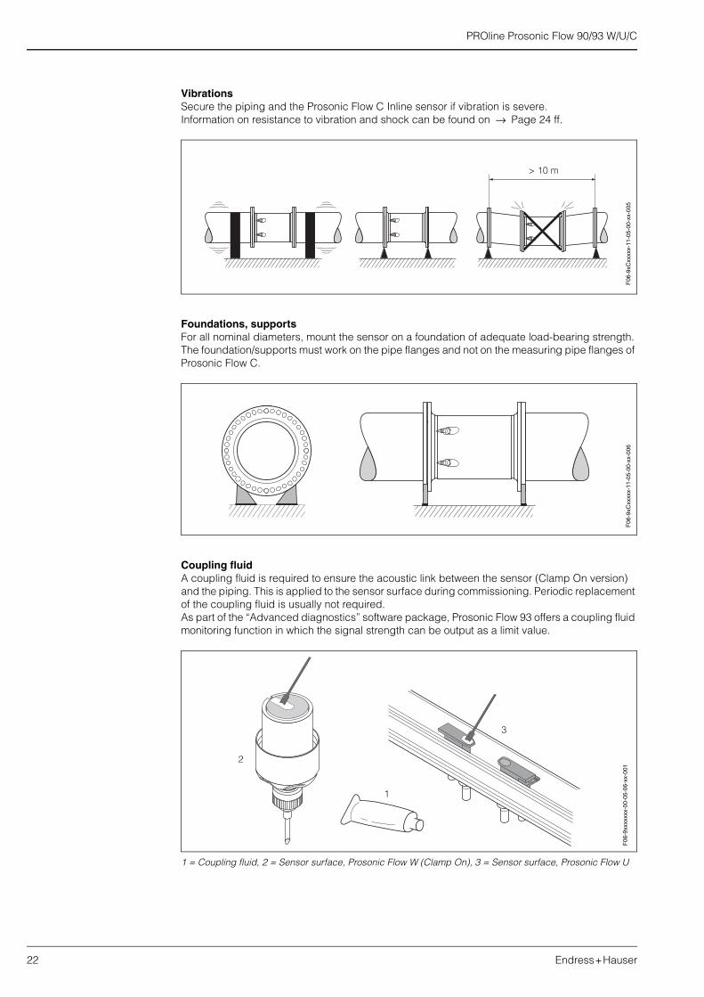
Vibrations Secure the piping and the Prosonic Flow C Inline sensor if vibration is severe.Information on resistance to vibration and shock can be found on → Page 24 ff.
Foundations, supportsFor all nominal diameters, mount the sensor on a foundation of adequate load-bearing strength. The foundation/supports must work on the pipe flanges and not on the measuring pipe flanges of Prosonic Flow C.
Coupling fluidA coupling fluid is required to ensure the acoustic link between the sensor (Clamp On version) and the piping. This is applied to the sensor surface during commissioning. Periodic replacement of the coupling fluid is usually not required.As part of the “Advanced diagnostics” software package, Prosonic Flow 93 offers a coupling fluid monitoring function in which the signal strength can be output as a limit value.
1 = Coupling fluid, 2 = Sensor surface, Prosonic Flow W (Clamp On), 3 = Sensor surface, Prosonic Flow U
> 10 m
F06
-9xC
xxxx
x-11
-05-
00-x
x-00
5F
06-9
xCxx
xxx-
11-0
5-00
-xx-
006
F06
-9xx
xxxx
x-00
-05-
06-x
x-00
1

PROline Prosonic Flow 90/93 W/U/C
Endress+Hauser 23
Sensor replacement, Prosonic Flow W InsertionThe active part of the sensor can be replaced without interrupting the process.
1 = Sensor connector, 2 = Small snap ring, 3 = Sensor cover, 4 = Spring, 5 = Large snap ring,6 = Sensor neck, 7 = Sensor element, 8 = Sensor holder
Sensor replacement, Prosonic Flow C InlineThe active part of the sensor can be replaced without interrupting the process.Prosonic Flow C Inline has 2 pairs of Prosonic Flow W Insertion sensors.
1 = Sensor connector, 2 = Sensor neck, 3 = O-ring, 4 = Sensor element, 5 = Sensor holder, 6 = Sensor support in measuring pipe Prosonic Flow C
Inlet and outlet run If possible, install the sensor well clear of fittings such as valves, T-pieces, elbows, etc. Compliance with the following requirements for the inlet and outlet runs is recommended to ensure measuring accuracy:
A = Prosonic Flow W and U (Clamp On versions)B = Prosonic Flow W (Insertion version) and Prosonic Flow C Inline(dimensions above the dimension line = single path version: dimensions below the dimension line = dual path version and Prosonic Flow C)1 = Valve, 2 = Pump, 3 = Two pipe bends in different directions
1 2 3 4 5 6 7 8 F06-
9xxx
xxxx
-17-
05-0
6-xx
-013
1 2 3 4 5 6
F06-
9xW
xxxx
x-11
-05-
06-x
x-00
0
≥ 15 x DN
≥ 40 x DN
≥ 20 x DN
≥ 40 x DN
≥ 5 x DN
1
2
3
≥ 15 x DN≥ 10 x DN
≥ 40 x DN≥ 40 x DN
≥ 20 x DN≥ 15 x DN
≥ 40 x DN≥ 20 x DN
≥ 5 x DN≥ 5 x DN
1
2
3
A B
F06
-9xx
xxxx
x-11
-05-
00-x
x-01
0

PROline Prosonic Flow 90/93 W/U/C
24 Endress+Hauser
Length of connecting cable Shielded cables are offered in the following lengths:5 m, 10 m, 15 m and 30 m (applies to all sensor versions)
Comply with the following instructions when mounting in order to achieve correct measuring results:Route the cable well clear of electrical machines and switching elements.
Environment
Ambient temperature range
• Transmitter Prosonic Flow 90/93:−20...+60 °C (optional: −40...+60 °C)
!Note:At ambient temperatures below −20°C, the readability of the display may be impaired.
• Flowrate measuring sensors Prosonic Flow W (Clamp On)–20...+80 C
• Flowrate measuring sensors Prosonic Flow U (Clamp On):–20...+60 °C
• Flowrate measuring sensors Prosonic Flow W (Insertion):–40...+80 C
• Prosonic Flow C Inline:– Measuring pipe: –10...+60 °C– Flowrate measuring sensors Prosonic Flow W (Inline): –40...+80 C
• Sound velocity measuring sensors DDU 18:–40...+80 °C
• Wall thickness measuring sensor DDU 19: 0...+60 C
• Sensor cable PTFE –40...+170 °C; sensor cable PVC –20...+70 °C
• In heated piping or piping conveying cold fluids, it is always permissible to insulate the piping completely with the mounted ultrasonic sensors.
• Install the transmitter at a shady location. Avoid direct sunlight, particularly in warm climatic regions.
Storage temperature The storage temperature corresponds to the ambient temperature range of the measuring transmitter and the relevant measuring sensors and the corresponding sensor cables (see above).
Degree of protection • Transmitter Prosonic Flow 90/93: IP 67 (NEMA 4X)
• Flowrate measuring sensors Prosonic Flow W (Clamp On):IP 67 (NEMA 4X), optional IP 68 (NEMA 6P)
• Flowrate measuring sensors Prosonic Flow U (Clamp On):IP 54
• Flowrate measuring sensors Prosonic Flow W (Insertion):IP 68 (NEMA 6P)
• Flowrate measuring sensors Prosonic Flow W (Inline):IP 68 (NEMA 6P)
• Sound velocity measuring sensors DDU 18:IP 68 (NEMA 6P)
• Wall thickness measuring sensor DDU 19:IP 67 (NEMA 4X)
Shock and vibration resistance
In accordance with IEC 68-2-6
Electromagnetic compatibility (EMC)
Electromagnetic compatibility (EMC requirements) according to EN 61326/A1 (IEC 1326) “Emission to class A requirements” and NAMUR Recommendation NE 21/43

PROline Prosonic Flow 90/93 W/U/C
Endress+Hauser 25
Process
Medium temperature range
• Flowrate measuring sensors Prosonic Flow W (Clamp On)–20...+80 C
• Flowrate measuring sensors Prosonic Flow U (Clamp On): –20...+80°C
• Flowrate measuring sensors Prosonic Flow W (Insertion):–40...+80 C
• Prosonic Flow C Inline:– Measuring pipe: –10...+60 °C (epoxy coated)– Flowrate measuring sensors Prosonic Flow W (Inline): –40...+80 C
• Sound velocity measuring sensors DDU 18:–40...+80 °C
• Wall thickness measuring sensor DDU 19: 0...+60 C
Medium pressure range(nominal pressure)
• Perfect measurement requires that the static fluid pressure is higher than vapor pressure.• Max. nominal pressure Prosonic Flow W (insertion): PN 16 (232 psi).
Pressure loss There is no pressure loss.

PROline Prosonic Flow 90/93 W/U/C
26 Endress+Hauser
Mechanical construction
Design, dimensions Dimensions of wall-mount housing, Prosonic Flow 90/93
Various mounting kits are available for the wall-mount housing. They can be ordered separately as an accessory from E+H. The following mounting versions are possible:
Esc
E- + 159.
590
.5
250
90
215
> 50 53 8181
135
45
192 11.511.5
102
9553
81.5
8 x
M5
F06
-x3x
xxxx
x-06
-03-
xx-x
x-00
0

PROline Prosonic Flow 90/93 W/U/C
Endress+Hauser 27
Panel mounting
A mounting kit, which can be ordered separately, is available for panel mounting the transmitter Prosonic Flow 90/93. Please contact your local E+H representative.
Pipe mounting (separate mounting kit)
A mounting kit, which can be ordered separately, is available for pipe mounting the transmitter Prosonic Flow 90/93. Please contact your local E+H representative.
245
~110
+0.
5–
0.5
210+0.5– 0.5
F06
-xxx
xxxx
x-06
-03-
06-x
x-00
2
Ø 2
0...7
0
~155
F06
-xxx
xxxx
x-06
-03-
06-x
x-00
1
PROline Prosonic Flow 90/93 W/U/C
28 Endress+Hauser
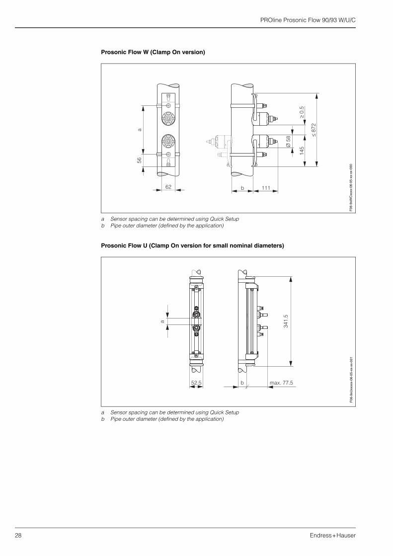
Prosonic Flow W (Clamp On version)
a Sensor spacing can be determined using Quick Setup b Pipe outer diameter (defined by the application)
Prosonic Flow U (Clamp On version for small nominal diameters)
a Sensor spacing can be determined using Quick Setupb Pipe outer diameter (defined by the application)
Ø 5
8
145
≥0.
5
≤87
2
111b
56
62
a
F06
-9xW
Cxx
xx-0
6-05
-xx-
xx-0
00
b
a
341.
5
max. 77.552.5
F06
-9xU
xxxx
x-06
-05-
xx-x
x-00
1

PROline Prosonic Flow 90/93 W/U/C
Endress+Hauser 29
Prosonic Flow W (Insertion version)Single path version
A = View A
a a = Pipe outer diameter (defined by the application)b b = Sensor spacing can be determined using Quick Setup c c = Path length can be determined using Quick Setup
Dual path version
B = View B
a a = Pipe outer diameter (defined by the application)b b = Sensor spacing can be determined using Quick Setup c c = Path length can be determined using Quick Setup
Arc length:
Offset:
A
A
c
b 25°
a ~ 150
Ø58
65
F06
-9xW
Ixxx
x-06
-05-
xx-x
x-00
0
Ø 58
80
x
La
α
a
B
B
25°
b
c
F06
-9xW
Ixxx
x-06
-05-
xx-x
x-00
1
LaΠ d α⋅ ⋅
360°---------------------=
)
x d αsin⋅2
--------------------=

PROline Prosonic Flow 90/93 W/U/C
30 Endress+Hauser
Prosonic Flow C InlineCalibrated measuring pipe with flowrate measuring sensors W
DN A B C L K
EN (DIN) PN 6[mm]
EN (DIN) PN 10[mm]
EN (DIN) PN 16[mm]
ANSI/ AWWA
[inch] [mm] [mm] [mm] [mm] [mm]
– 300 – – 520 317.5 165.1 500 445
– – 300 – 517 313.9 163.2 500 460
– – – 12" 517 313.9 163.2 500 482.6
– 350 – – 548 350 182 550 505
– – 350 – 546 348 181 550 520
– – – 14" 544 346 179.9 550 533.4
– 400 – – 590 400 208 600 565
– – 400 – 589 398 207 600 580
– – – 16" 587 396 205.9 600 596.9
– – – 18" 629 445 231.4 650 635
– 500 – – 676 500 260 650 670
– – 500 – 674 498 259 650 715
– – – 20" 672 496 257.9 650 699
– 600 – – 763 602 313 780 780
– – 600 – 760 598 311 780 840
– – – 24" 756 594 308.9 780 813
– 700 – – 848 701 364.5 910 895
– – 700 – 842 695 361.4 910 910
– – – 28" 846 699 363.5 910 927.1
– – – 30" 889 750 390 975 984.25
– 800 – – 935 803 417.6 1040 1015
– – 800 – 930 797 414.4 1040 1025
– – – 32" 933 801 416.5 1040 1060.45
K
C
B
L
A
F06
-9xC
xxxx
x-06
-05-
xx-x
x-00
0

PROline Prosonic Flow 90/93 W/U/C
Endress+Hauser 31
– 900 – – 1019 902 469 1170 1115
– – 900 – 1012 894 464.9 1170 1125
– – – 36" 1016 898 467 1170 1168.4
– 1000 – – 1106 1004 522.1 1300 1230
– – 1000 – 1100 996 517.9 1300 1255
– – – 40" 1103 1000 520 1300 1289.05
– – – 42" 1147 1051 546.5 1365 1346.2
1200 – – – 1282 1210 629.2 1560 1405
– 1200 – – 1277 1204 626.1 1560 1455
– – 1200 – 1270 1196 621.9 1560 1485
– – – 48" 1274 1200 624 1560 1511.3
– – – 54" 1399 1347 700.4 1755 1682.75
1400 – – – 1453 1410 733.2 1820 1630
– 1400 – – 1448 1404 730.1 1820 1675
– – 1400 – 1441 1396 725.9 1820 1685
– – – 60" 1530 1500 780 1950 1854.2
1600 – – – 1622 1608 836.2 2080 1830
– 1600 – – 1615 1600 832 2080 1915
– – 1600 – 1607 1590 826.8 2080 1930
– – – 66" 1655 1646 855.9 2145 2032
1800 – – – 1793 1808 940.2 2340 2045
– 1800 – – 1786 1800 936 2340 2115
– – 1800 – 1776 1788 929.8 2340 2130
– – – 72" 1778 1790 930.8 2340 2197.1
2000 – – – 1961 2004 1042.1 2600 2265
– 2000 – – 1954 1996 1037.9 2600 2325
– – 2000 – 1943 1984 1031.7 2600 2345
– – – 78" 1949 1990 1034.8 2600 2362.2
The fitting length (L) is always the same per nominal diameter, regardless of the pressure rating selected.
DN A B C L K
EN (DIN) PN 6[mm]
EN (DIN) PN 10[mm]
EN (DIN) PN 16[mm]
ANSI/ AWWA
[inch] [mm] [mm] [mm] [mm] [mm]

PROline Prosonic Flow 90/93 W/U/C
32 Endress+Hauser
Weight Transmitter:
Measuring sensors:
• Wall-mount housing Prosonic Flow 90/93 6.0 kg
• Prosonic Flow W (Clamp On) incl. tensioning bands 2.8 kg
• Prosonic Flow U (Clamp On) incl. tensioning bands 1 kg
• Prosonic Flow W (Insertion / single path version) 4.5 kg
• Prosonic Flow W (Insertion / dual path version) 12.0 kg
• Sound velocity measuring sensors DDU 18 incl. tensioning bands 2.4 kg
• Wall thickness measuring sensor DDU 19 incl. tensioning band 1.5 kg
• Prosonic Flow C (Inline)
Nominal diameter Measuring pipe incl. measuring sensors in kg
[mm] [inch] EN (DIN)PN 6
EN (DIN)PN 10
EN (DIN)PN 16
ANSIClass 150
AWWAClass D
300 12" – 41.8 59.6 77.2 –
350 14" – 54.7 70.1 111.2 –
400 16" – 66.4 90.3 139.6 –
– 18" – – – 162.7 –
500 20" – 96.8 145.9 197.8 –
600 24" – 120.4 196.6 287.9 –
700 28" – 183.6 251.3 – 229.9
– 30" – – – – 265.1
800 32" – 245.0 327.0 – 323.9
900 36" – 313.7 456.3 – 455.6
1000 40" – 379.0 587.3 – 552.6
– 42" – – – – 626.1
1200 48" 434.6 678.6 941.7 – 894.7
– 54" – – – – 1280.2
1400 – 569.2 907.6 1267.6 – –
– 60" – – – – 1584.5
1600 – 818.7 1381.4 2012.0 – –
– 66" – – – – 2268.0
1800 72" 993.5 1726.7 2608.2 – 2707.0
2000 78" 1508.2 2393.6 3601.3 – 3073.9
(Weight data valid for standard pressure ratings and without packaging material)

PROline Prosonic Flow 90/93 W/U/C
Endress+Hauser 33
Material Transmitter Prosonic Flow 90/93:• Wall-mounted housing: powder coated die-cast aluminium
Prosonic Flow W (Clamp On):• Sensor housing: 1.4301/DIN 17440 (304/AISI)• Sensor holder (cast steel): 1.4308/DIN 17440 (CF-8/AISI)• Sensor contact surfaces: chemically resistant plastic• Tensioning bands: 1.4301/DIN 17440 (304/AISI)
Prosonic Flow U (Clamp On):• Sensor housing: plastic• Frame ends (cast steel): 1.4308/DIN 17440 (CF-8/AISI)• Sensor securing rail (aluminium alloy): EN AW-6063/DIN EN 573-3 (AA 6063/UNS)• Sensor contact surfaces: chemically resistant plastic• Tensioning bands: 1.4301/DIN 17440 (304/AISI)
Prosonic Flow W (Insertion):• Sensor housing: 1.4404/DIN 17440 (316L/AISI)• Weld-in parts: 1.4301/DIN 17440 (304/AISI)
Prosonic Flow C (Inline)• Sensor housing: 1.4404/DIN 17440 (316L/AISI)• Weld-in parts: 1.4404/DIN 17440 (316L/AISI)• Measuring pipe: ST 37.2 (carbon steel)
Prosonic Flow DDU 18 and DDU 19:• Sensor housing: 1.4301/DIN 17440 (304/AISI)
Standard sensor cable:• Cable connector (nickled brass): 2.0401/DIN 17660 (C38500/UNS)• Cable sheath: PVC
High temperature sensor cable:• Cable connector (stainless steel): 1.4301/DIN 17440 (304/AISI)• Cable sheath: PTFE
Human interface
Display elements • Liquid crystal display: illuminated, two-line (Prosonic Flow 90) or four-line (Prosonic Flow 93) each with 16 characters
• Custom configurations for presenting different measured values and status variables• Totalizer:
Prosonic Flow 90: 1 totalizerProsonic Flow 93: 3 totalizers
Operating elements Uniform operating concept for both transmitter types:
Prosonic Flow 90:• Local operation with three keys (–, +, E)• Quick Setup menu for quick commissioning
Prosonic Flow 93:• Local operation with three optical keys (–, +, E)• Application-specific Quick Setup menus for quick commissioning

PROline Prosonic Flow 90/93 W/U/C
34 Endress+Hauser
Remote operation Prosonic Flow 90:Operation via HART, PROFIBUS PA
Prosonic Flow 93:Operation via HART, PROFIBUS DP/PA, FOUNDATION Fieldbus
Language group • Language group for western Europe and America, contains the languages English, German, Spanish, Italian, French, Dutch and Portuguese
• Language group for northern Europe/Scand., contains the languages English, Russian, Polish, Norwegian, Finnish, Swedish and Czech
• Language group for southern/eastern Asia, contains the languages English, Japanese and Indonesian
Certificates and approvals
Ex approval The transmitter housing (wall-mount housing) is suitable for use in ATEX II3G (Ex Zone 2).
Information about currently available Ex versions (ATEX, FM, CSA, etc.) can be supplied by your E+H Sales Centre on request. All explosion protection data are given in a separate documentation which is available upon request.
PROFIBUS PA certification
The flow device has successfully passed all the test procedures carried out and is certified and registered by the PNO (PROFIBUS User Organisation). The device thus meets all the requirements of the following specifications:
• Certified to PROFIBUS PA, profile version 3.0 (device certification number: on request)• The device can also be operated with certified devices of other manufacturers (interoperability)
FOUNDATION Fieldbus certification
The flow device has successfully passed all the test procedures carried out and is certified and registered by the Fieldbus FOUNDATION. The device thus meets all the requirements of the following specifications:
• Certified to FOUNDATION Fieldbus Specification• The device meets all the specifications of the FOUNDATION Fieldbus H1.• Interoperability Test Kit (ITK), revision status 4.0 (device certification number: on request)• The device can also be operated with certified devices of other manufacturers• Physical Layer Conformance Test of the Fieldbus FOUNDATION
CE mark The measuring system is in conformity with the statutory requirements of the EC Directives. Endress+Hauser confirms successful testing of the device by affixing to it the CE mark.
Other standards and guidelines
EN 60529:Degrees of protection by housing (IP code)
EN 61010:Protection measures for electrical equipment for measurement, control, regulation and laboratory procedures
EN 61326 (IEC 1326):Electromagnetic compatibility (EMC requirements)
NAMUR NE 21:Association for Standards for Control and Regulation in the Chemical Industry
NAMUR NE 43Standardisation of the signal level for the breakdown information of digital transmitters with analogue output signal.

PROline Prosonic Flow 90/93 W/U/C
Endress+Hauser 35
Ordering information
The E+H service organisation can provide detailed ordering information and information on specific order codes on request.
Accessories
Measuring sensors: • DDU 18 (sound velocity measuring sensors)• DDU 19 (wall thickness measuring sensor)
Pipe mounting kit for transmitter:• Wall-mount housing
Mounting material for Clamp On versions:• Coupling fluid –40...+80 °C• Coupling fluid 0...170 °C
- Prosonic Flow W• Tensioning bands for DN 50...200• Tensioning bands for DN 200...600• Tensioning bands for DN 600...2000• Tensioning bands for DN 2000...4000
- Prosonic Flow U• Tensioning bands for DN 15...40• Tensioning bands for DN 32...65• Tensioning bands for DN 50...100
More detailed information can be obtained from your E+H service organisation.
Documentation
System Information Prosonic Flow 90/93 (SI 034D/06/en)
Technical Information Prosonic Flow 93 P (TI 056D/06/en)
Operating Instructions Prosonic Flow 90 (BA 068D/06/en and BA 069D/06/en)
Operating Instructions Prosonic Flow 90 PROFIBUS PA (BA 074D/06/en and BA 075D/06/en)
Operating Instructions Prosonic Flow 93 (BA 070D/06/en and BA 071D/06/en)
Operating Instructions Prosonic Flow 93 PROFIBUS DP/PA (BA 076D/06/en and BA 077D/06/en)
Operating Instructions Prosonic Flow 93 FOUNDATION Fieldbus (BA 078D/06/en and BA 079D/06/en)
Operating Instructions Prosonic Flow 93 C Inline(BA 087D/06/en and BA 088D/06/en)
Operating Instructions Prosonic Flow 93 C Inline PROFIBUS PA(BA 089D/06/en and BA 090D/06/en)
Operating Instructions Prosonic Flow 93 C Inline FOUNDATION Fieldbus(BA 091D/06/en and BA 092D/06/en)
You can order the documents from your E+H service organisation or download them from the Internet addresses given on the last page.

Subject to modification
Endress+Hauser GmbH+Co.Instruments InternationalP.O. Box 2222D-79574 Weil am RheinGermany
Tel. (07621) 975-02Tx 773926Fax (07621) 975 345e-mail: [email protected]
Internet:http://www.endress.com
11.01
TI057D/06/en/10.0350099325FM+SGML 6.0