Embed Size (px)
Citation preview

Tilt Column for the CorvairFlaming River Corvette Column and Quick steering box
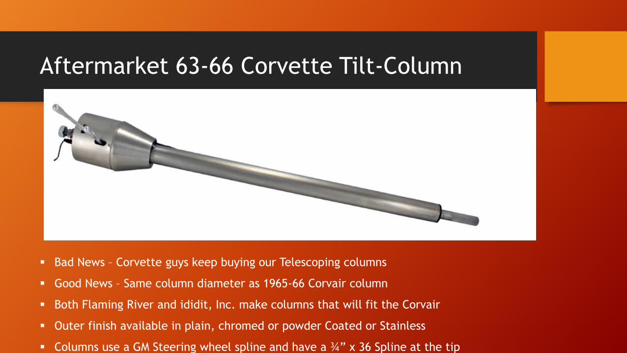
Aftermarket 63-66 Corvette Tilt-Column
Bad News – Corvette guys keep buying our Telescoping columns
Good News – Same column diameter as 1965-66 Corvair column
Both Flaming River and ididit, Inc. make columns that will fit the Corvair
Outer finish available in plain, chromed or powder Coated or Stainless
Columns use a GM Steering wheel spline and have a ¾” x 36 Spline at the tip
Corvette Column P/N FR2000VTABK (black)
• Original Application 63-66 Corvette (1.5” diameter column)
• Corvair Fast Ratio Steering Box
• Flaming River Hub Adapter
• Lower U-joint
• Upper Bushing
• Splined Shaft 10”
• Loctite solution
Partial Parts List for Install
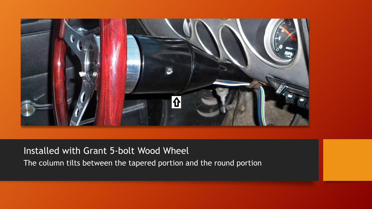
Installed with Grant 5-bolt Wood Wheel
The column tilts between the tapered portion and the round portion

Early or Late Column Design ? Early
Early 65 Style Column ?
• Long shaft from inside box to steering Wheel- One piece
• Flange clamps to the column at the firewall mount
• Three bolts go through flange, directly to nuts mounted in floor
• OEM Column housing is separate from the steering shaft – it just slides off
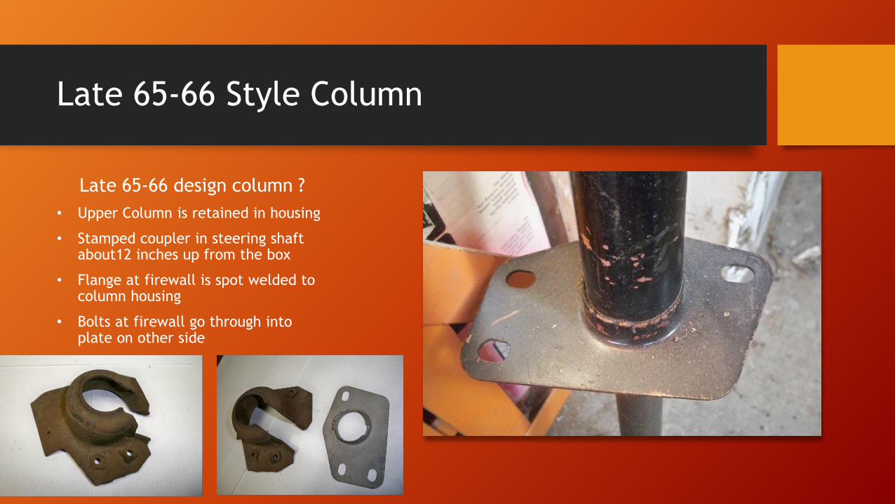
Late 65-66 Style Column
Late 65-66 design column ?
• Upper Column is retained in housing
• Stamped coupler in steering shaft about12 inches up from the box
• Flange at firewall is spot welded to column housing
• Bolts at firewall go through into plate on other side
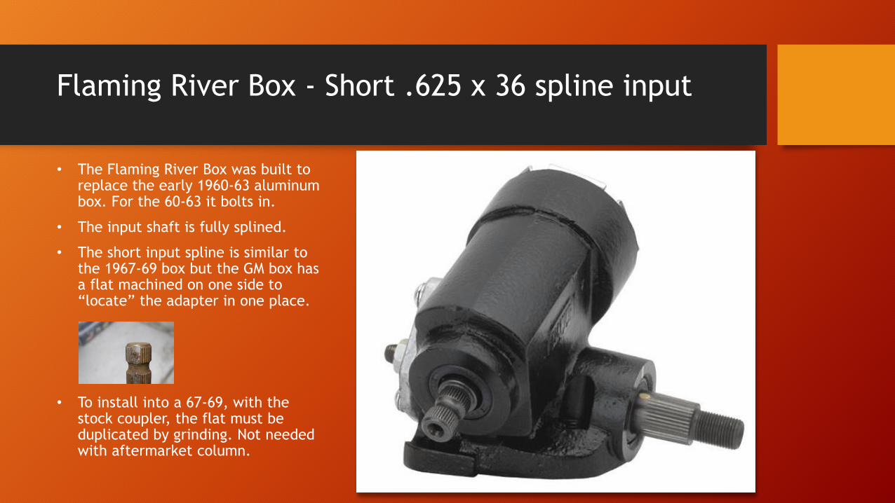
Flaming River Box - Short .625 x 36 spline input
• The Flaming River Box was built to replace the early 1960-63 aluminum box. For the 60-63 it bolts in.
• The input shaft is fully splined.
• The short input spline is similar to the 1967-69 box but the GM box has a flat machined on one side to “locate” the adapter in one place.
• To install into a 67-69, with the stock coupler, the flat must be duplicated by grinding. Not needed with aftermarket column.
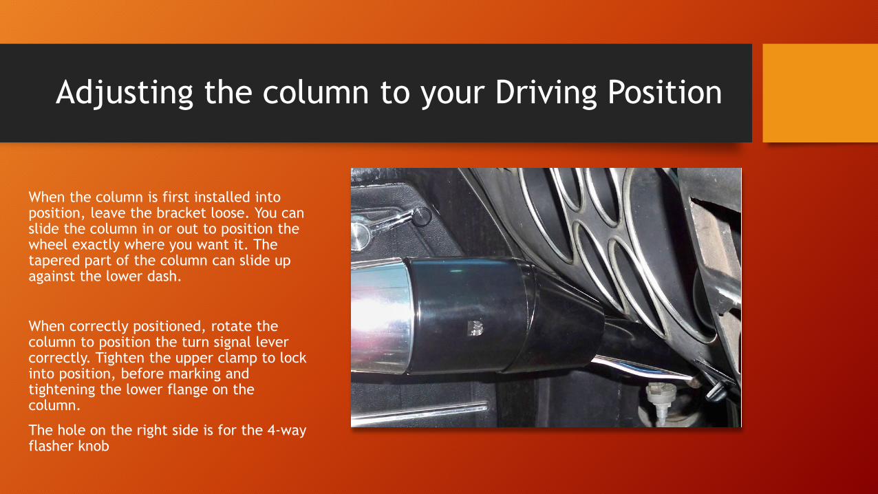
Adjusting the column to your Driving Position
When the column is first installed into position, leave the bracket loose. You can slide the column in or out to position the wheel exactly where you want it. The tapered part of the column can slide up against the lower dash.
When correctly positioned, rotate the column to position the turn signal lever correctly. Tighten the upper clamp to lock into position, before marking and tightening the lower flange on the column.
The hole on the right side is for the 4-way flasher knob
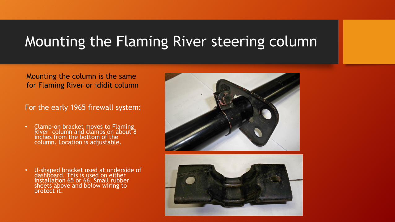
Mounting the Flaming River steering column
For the early 1965 firewall system:
• Clamp-on bracket moves to Flaming River column and clamps on about 8 inches from the bottom of the column. Location is adjustable.
• U-shaped bracket used at underside of dashboard. This is used on either installation 65 or 66. Small rubber sheets above and below wiring to protect it.
Mounting the column is the same
for Flaming River or ididit column
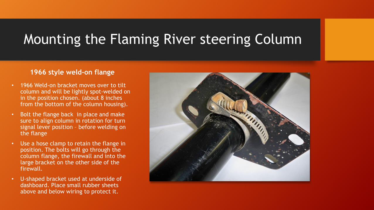
Mounting the Flaming River steering Column
• 1966 Weld-on bracket moves over to tilt column and will be lightly spot-welded on in the position chosen. (about 8 inches from the bottom of the column housing).
• Bolt the flange back in place and make sure to align column in rotation for turn signal lever position – before welding on the flange
• Use a hose clamp to retain the flange in position. The bolts will go through the column flange, the firewall and into the large bracket on the other side of the firewall.
• U-shaped bracket used at underside of dashboard. Place small rubber sheets above and below wiring to protect it.
1966 style weld-on flange
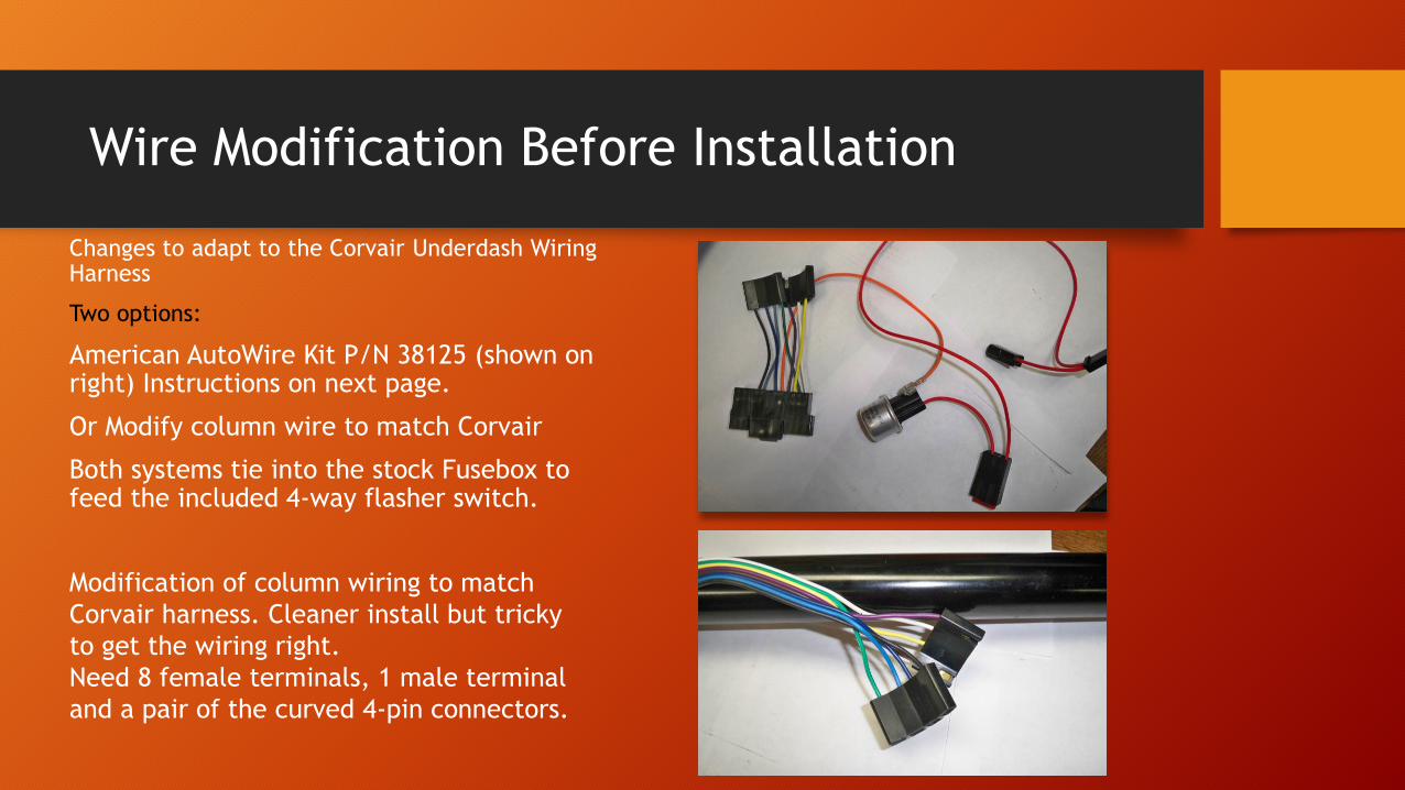
Wire Modification Before Installation
Changes to adapt to the Corvair Underdash Wiring Harness
Two options:
American AutoWire Kit P/N 38125 (shown on right) Instructions on next page.
Or Modify column wire to match Corvair
Both systems tie into the stock Fusebox to feed the included 4-way flasher switch.
Modification of column wiring to match
Corvair harness. Cleaner install but tricky
to get the wiring right.
Need 8 female terminals, 1 male terminal
and a pair of the curved 4-pin connectors.
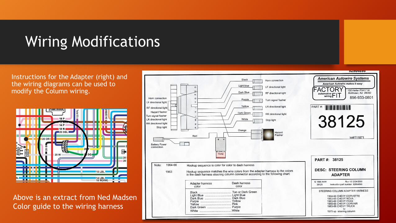
Wiring Modifications
Instructions for the Adapter (right) and the wiring diagrams can be used to modify the Column wiring.
Above is an extract from Ned Madsen
Color guide to the wiring harness
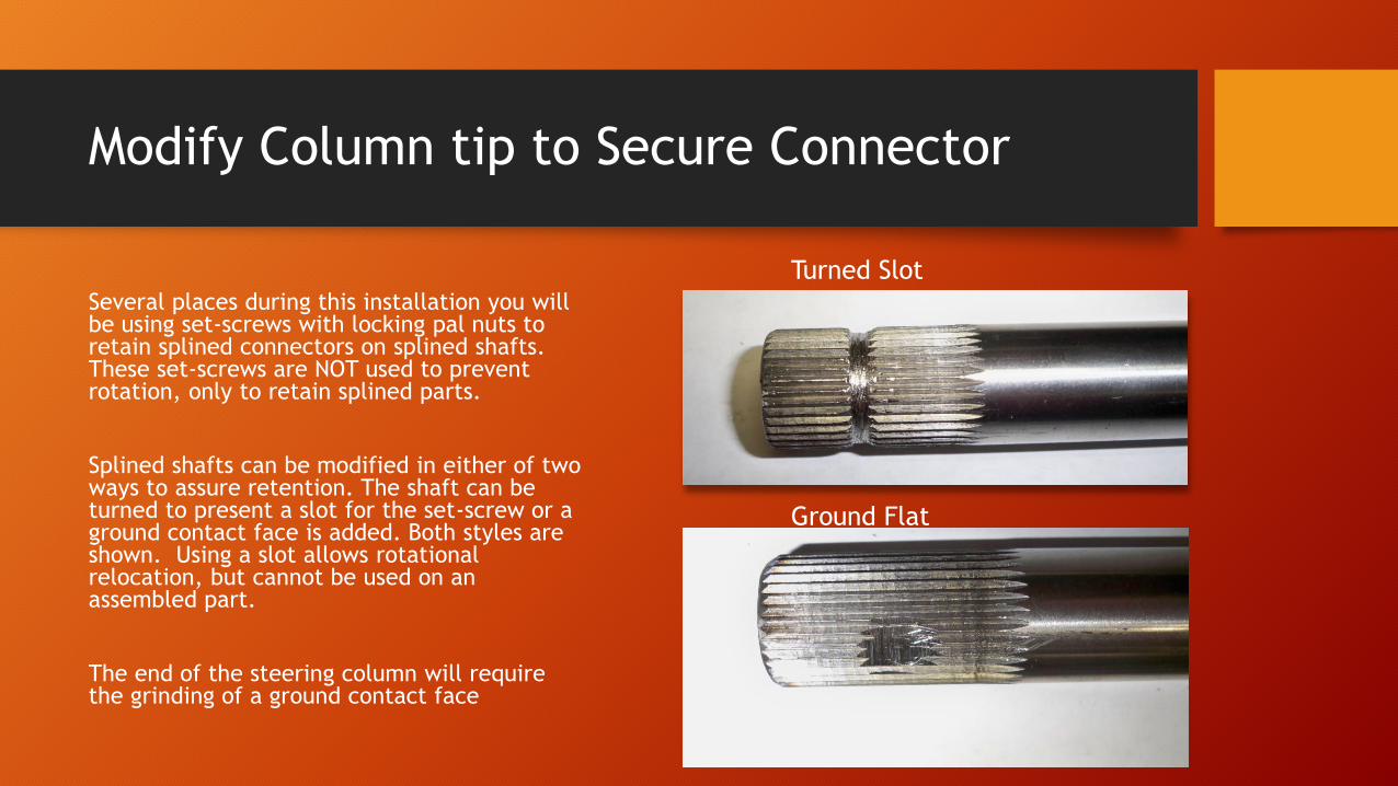
Modify Column tip to Secure Connector
Several places during this installation you will be using set-screws with locking pal nuts to retain splined connectors on splined shafts. These set-screws are NOT used to prevent rotation, only to retain splined parts.
Splined shafts can be modified in either of two ways to assure retention. The shaft can be turned to present a slot for the set-screw or a ground contact face is added. Both styles are shown. Using a slot allows rotational relocation, but cannot be used on an assembled part.
The end of the steering column will require the grinding of a ground contact face
Turned Slot
Ground Flat
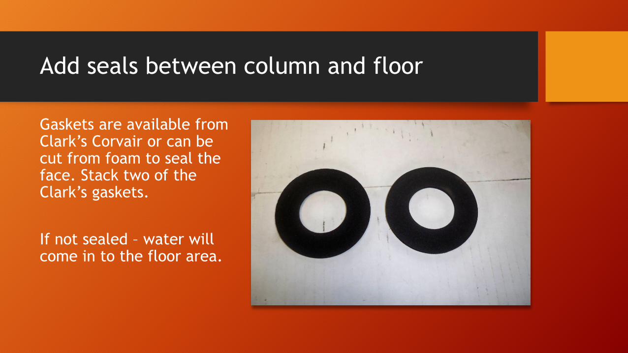
Add seals between column and floor
Gaskets are available from Clark’s Corvair or can be cut from foam to seal the face. Stack two of the Clark’s gaskets.
If not sealed – water will come in to the floor area.
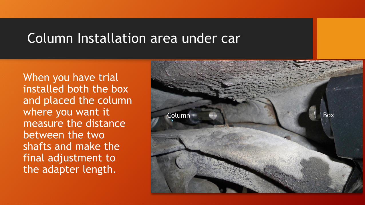
Column Installation area under car
When you have trial installed both the box and placed the column where you want it measure the distance between the two shafts and make the final adjustment to the adapter length.
BoxColumn
Intermediate shaft options- Solid or Collapsible
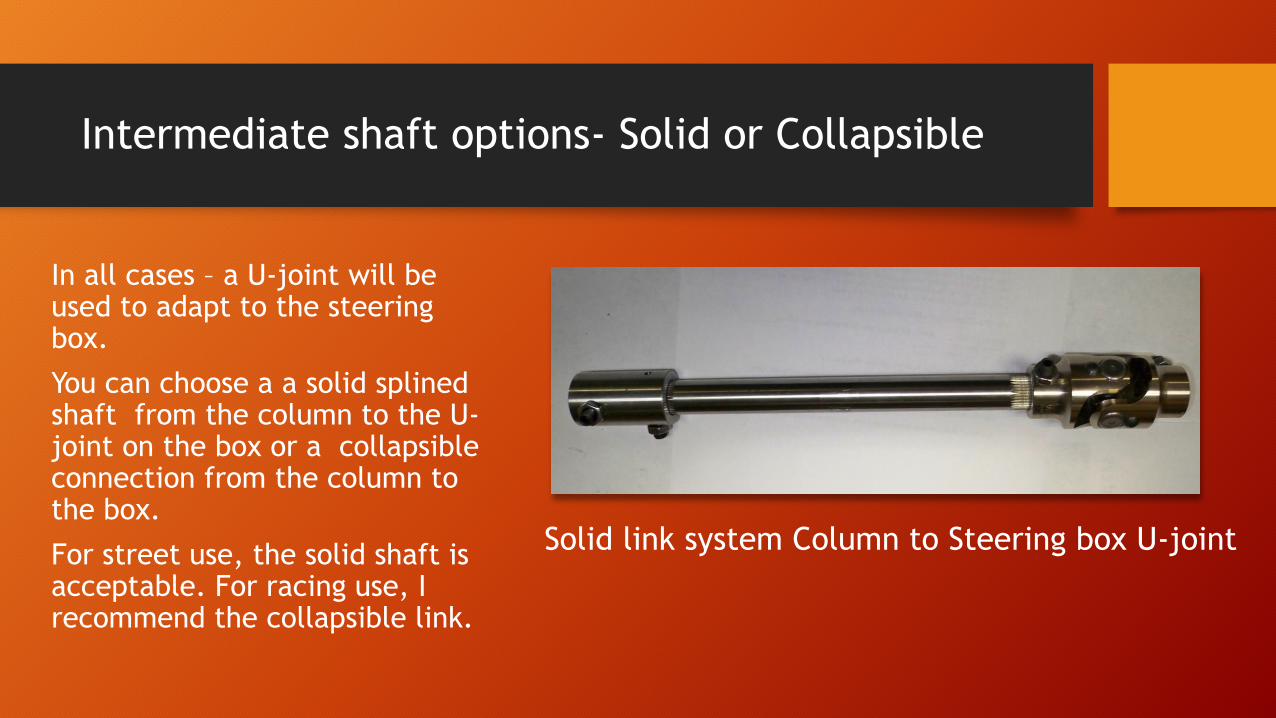
In all cases – a U-joint will be used to adapt to the steering box.
You can choose a a solid splined shaft from the column to the U-joint on the box or a collapsible connection from the column to the box.
For street use, the solid shaft is acceptable. For racing use, I recommend the collapsible link.
Solid link system Column to Steering box U-joint
Upper Adapter Solid shaft
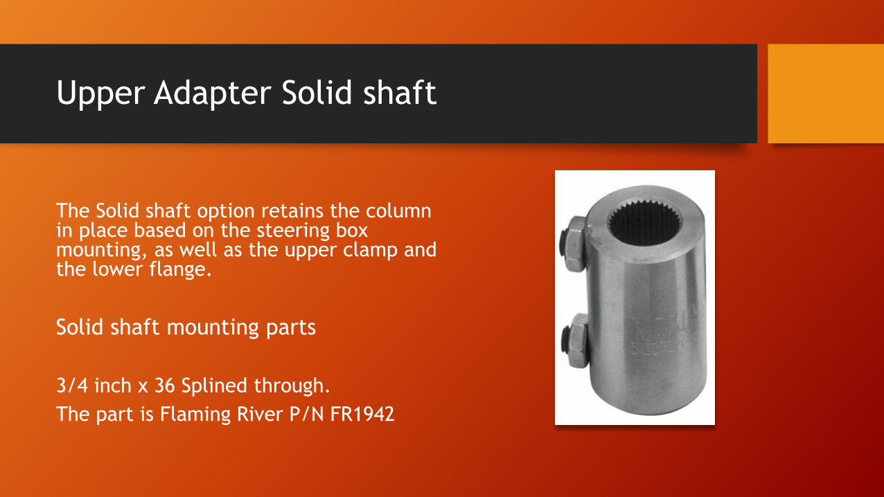
The Solid shaft option retains the column in place based on the steering box mounting, as well as the upper clamp and the lower flange.
Solid shaft mounting parts
3/4 inch x 36 Splined through.
The part is Flaming River P/N FR1942
Lower U-joint solid shaft
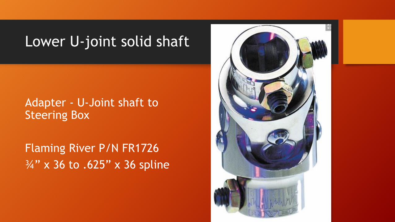
Adapter - U-Joint shaft to Steering Box
Flaming River P/N FR1726
¾” x 36 to .625” x 36 spline
Intermediate solid shaft 10 to 12 inches
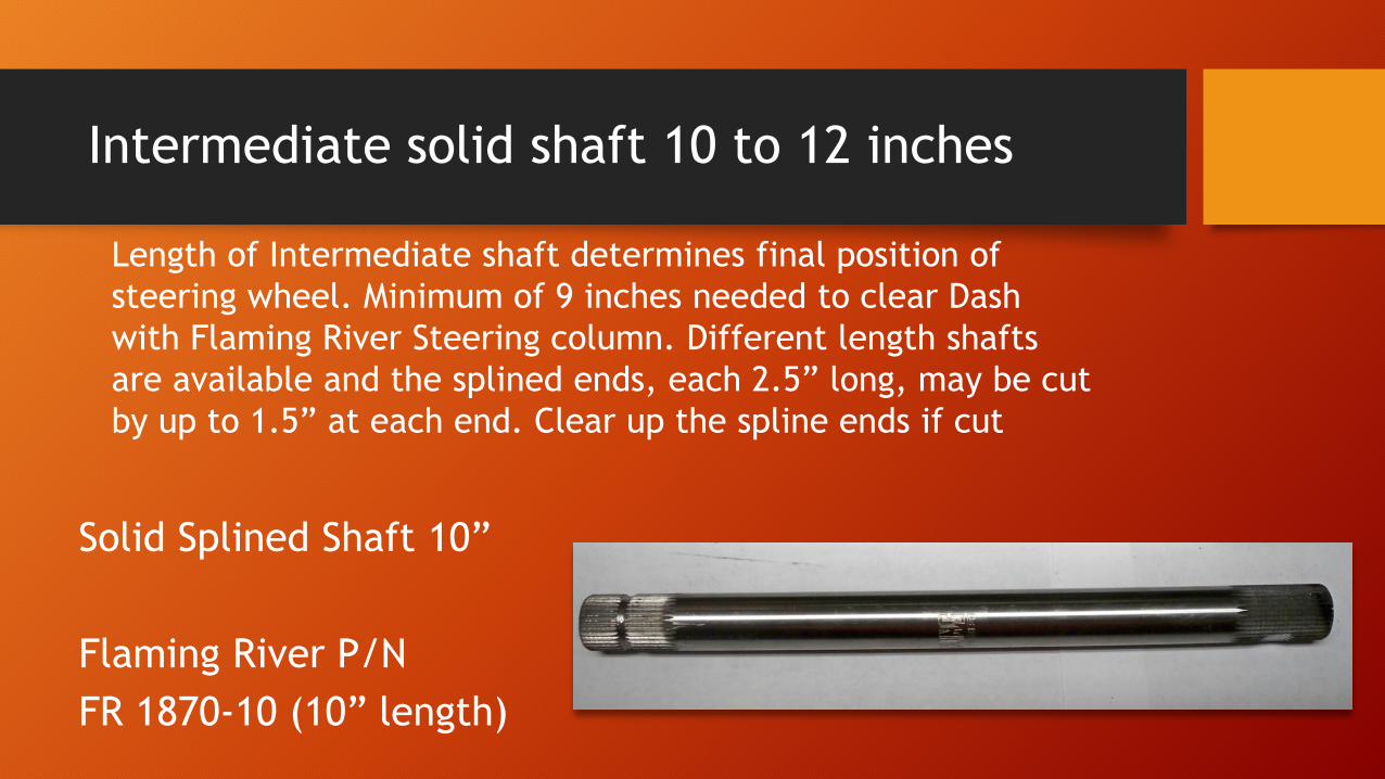
Solid Splined Shaft 10”
Flaming River P/N
FR 1870-10 (10” length)
Length of Intermediate shaft determines final position of
steering wheel. Minimum of 9 inches needed to clear Dash
with Flaming River Steering column. Different length shafts
are available and the splined ends, each 2.5” long, may be cut
by up to 1.5” at each end. Clear up the spline ends if cut
Intermediate shaft options – Collapsible
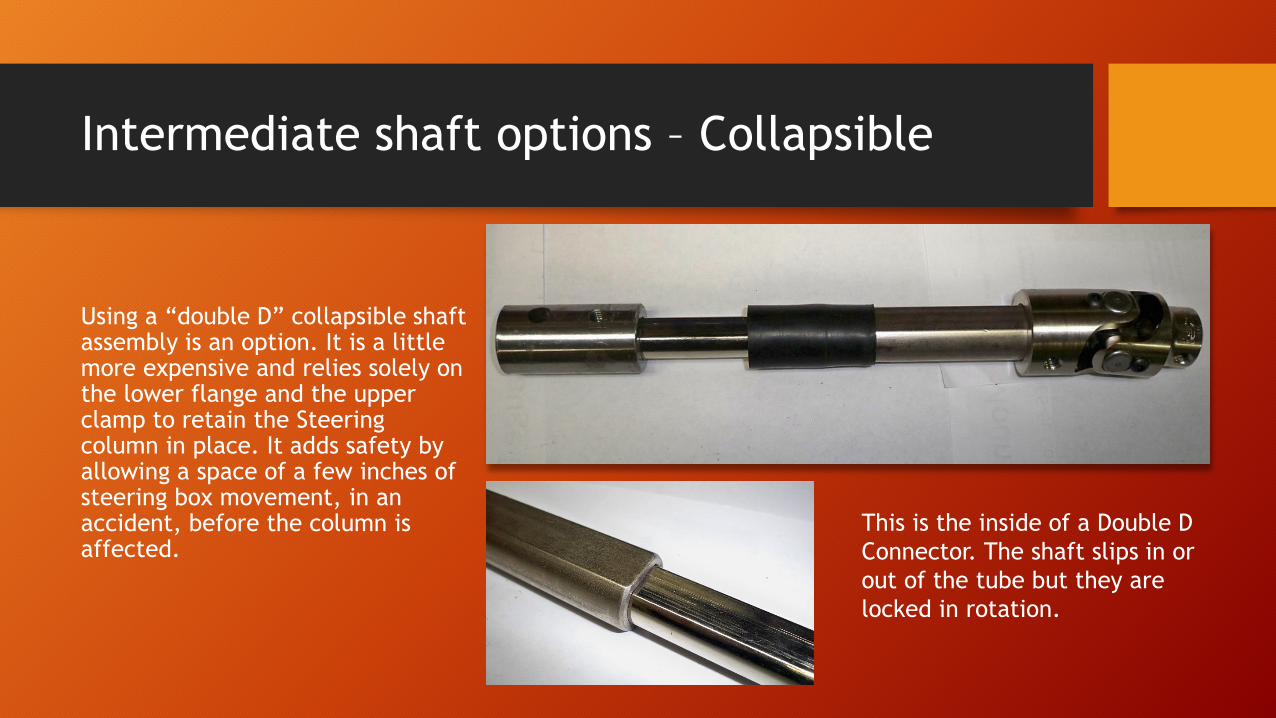
Using a “double D” collapsible shaft assembly is an option. It is a little more expensive and relies solely on the lower flange and the upper clamp to retain the Steering column in place. It adds safety by allowing a space of a few inches of steering box movement, in an accident, before the column is affected.
This is the inside of a Double D
Connector. The shaft slips in or
out of the tube but they are
locked in rotation.
Final Installation - Wiring
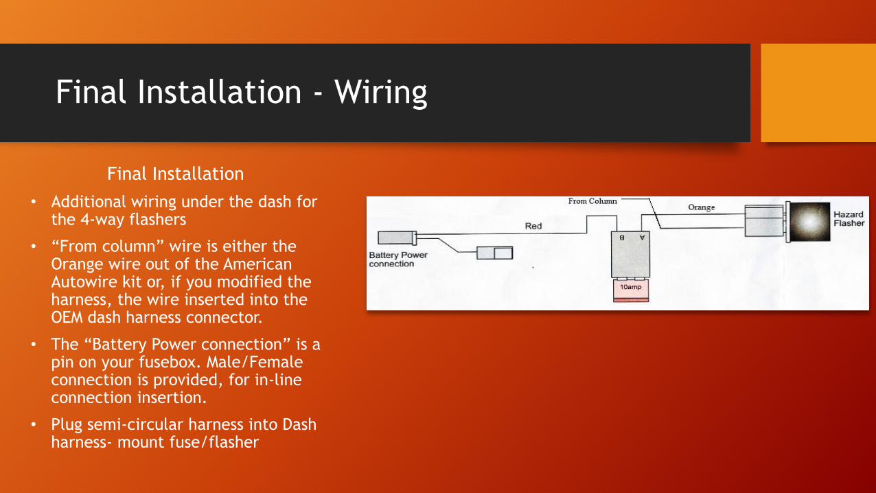
Final Installation
• Additional wiring under the dash for the 4-way flashers
• “From column” wire is either the Orange wire out of the American Autowire kit or, if you modified the harness, the wire inserted into the OEM dash harness connector.
• The “Battery Power connection” is a pin on your fusebox. Male/Female connection is provided, for in-line connection insertion.
• Plug semi-circular harness into Dash harness- mount fuse/flasher

Final Installation - Mechanical
• All slip joints, whether splined or double D will use set-screws and lock nuts. Use Loctite on the set-screw threads.
• All slip joints will have a ground face or a turned section for the set-screw to enter. This mechanically secures the joint.
• U-joints must be installed with care. Make sure the shaft does not protrude too far into the U-joint, blocking the flexibility of the joint. See Arrow. Note how the splined shaft is secured short of touching the movable part of the U-joint.
Final Installation Mechanical
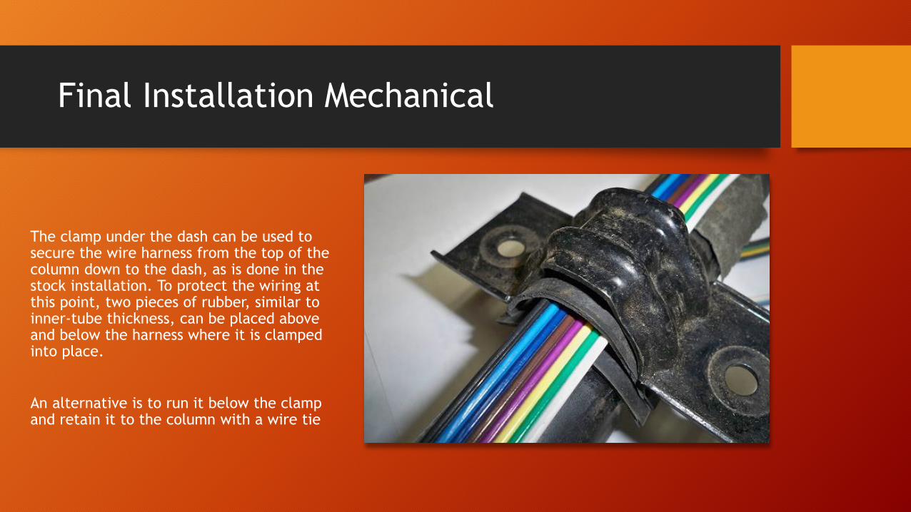
The clamp under the dash can be used to secure the wire harness from the top of the column down to the dash, as is done in the stock installation. To protect the wiring at this point, two pieces of rubber, similar to inner-tube thickness, can be placed above and below the harness where it is clamped into place.
An alternative is to run it below the clamp and retain it to the column with a wire tie

Questions?
Some Handouts are available
Some part samples are on display