Embed Size (px)
Citation preview

37
TILT-UP LIFTING PRODUCTS
www.MeadowBurke.com 877-518-7665 MB1109
Tilt-Up Manual
www.MeadowBurke.com 877-518-7665
Tilt-Up Manual
Su
per-
Lif
t

STRONGBACKS
When will they be needed?
A. If a panel looks like it would fall over when standing up. The strongback acts as a crutch to balance the weight.
B. When panels have very wide openings. The strongback keeps the panel from sagging under the opening.
C. When panels have “wimpy” legs, less than 7” thick, where the height of the leg divided by the width of the leg is less than 0.12. A strongback is needed because the leg cannot support the weight of the panel bearing on it during lift. For legs 7” and thicker often ties can be added around the reinforcing to avoid strongbacks.
D. To avoid large amounts of added reinforcing. In certain instances, strongbacks are cheaper.
How to attach strongbacks properly
Using splice plates on 8” channel allows a “hinge” to form thereby reducing the capacity on the strongback, depending on the loca-tion of the splice. So it’s important to know where to splice a strongback.
1. Strongback Legs - We do not want the hinge to occur between H/2 + 3’0 above the Double Lift Plate.
H - is the distance from bottom of panel to DBL coil.
H/2 - 1/2 of that distance. If you have a notch that is 12’, it’s 1/2 of 12’ or 6 + 3 = 9’. You can’t have a splice in that 9’.
2. Second condition is strongbacks spanning openings. We don’t want the splice to occur within 3’ above to 3’ below the first strongback insert around the opening.
877-518-7665 www.MeadowBurke.com MB1109
Tilt-Up Manual
38
877-518-7665 www.MeadowBurke.com
Tilt-Up Manual

39
STRONGBACKS
Special Requirements
This section covers a few of the conditions that will normally require the use of wood or steel strongbacks. If your project haspanel configurations that are similar to the conditions shown in this section, it is very likely strongbacks will be required to lift thepanels. Please remember that this is a guideline of some of the more common cases and does not cover all of the many possiblerequirements for strongbacks.
Panels with Stepped Bottoms
1. The bottom of the panel must be relatively straight in order for it to rotate properly. When a portion of the bottom end of the panel does not contact the ground, a strongback leg may be rebuilt to provide support for the panel. The three stepconditions shown represent cases where strongbacks may be required to provide support.
www.MeadowBurke.com 877-518-7665 MB1109
Tilt-Up Manual
Su
per-
Lif
t
Panels with Sloped Bottoms
2. When the bottom of a panel slopes, strongback legs may be required to ensure the panel lifts straight. As a general rule, if the slope of the bottom end of the panel has a rise of 4” or more per 10’ of panel width, strongback legs will be required. The following conditions are common and will normally need strongback legs to lift.
www.MeadowBurke.com 877-518-7665
Tilt-Up Manual
STRONGBACKS
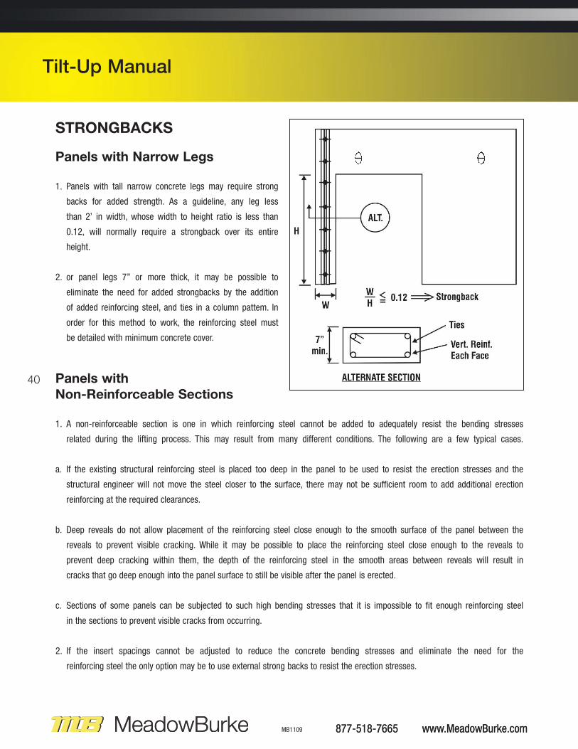
Panels with Narrow Legs
1. Panels with tall narrow concrete legs may require strong
backs for added strength. As a guideline, any leg less
than 2’ in width, whose width to height ratio is less than
0.12, will normally require a strongback over its entire
height.
2. or panel legs 7” or more thick, it may be possible to
eliminate the need for added strongbacks by the addition
of added reinforcing steel, and ties in a column pattem. In
order for this method to work, the reinforcing steel must
be detailed with minimum concrete cover.
877-518-7665 www.MeadowBurke.com MB1109
Tilt-Up Manual
40 Panels with Non-Reinforceable Sections
1. A non-reinforceable section is one in which reinforcing steel cannot be added to adequately resist the bending stresses
related during the lifting process. This may result from many different conditions. The following are a few typical cases.
a. If the existing structural reinforcing steel is placed too deep in the panel to be used to resist the erection stresses and the
structural engineer will not move the steel closer to the surface, there may not be sufficient room to add additional erection
reinforcing at the required clearances.
b. Deep reveals do not allow placement of the reinforcing steel close enough to the smooth surface of the panel between the
reveals to prevent visible cracking. While it may be possible to place the reinforcing steel close enough to the reveals to
prevent deep cracking within them, the depth of the reinforcing steel in the smooth areas between reveals will result in
cracks that go deep enough into the panel surface to still be visible after the panel is erected.
c. Sections of some panels can be subjected to such high bending stresses that it is impossible to fit enough reinforcing steel
in the sections to prevent visible cracks from occurring.
2. If the insert spacings cannot be adjusted to reduce the concrete bending stresses and eliminate the need for the
reinforcing steel the only option may be to use external strong backs to resist the erection stresses.
877-518-7665 www.MeadowBurke.com
Tilt-Up Manual

41
www.MeadowBurke.com 877-518-7665 MB1109
Tilt-Up Manual
Su
per-
Lif
t
STRONGBACKS
Panels with an Opening Separating Concrete Areas
Certain panel configurations make it difficult to place lifting inserts in the concrete areas that they must pick up. This normally occurs when large openings are placed in the panels and the inserts can be located on only one side of the opening. Astrongback is used to span across the opening like an arm to pick up the concrete on the opposite side. The following cases areexamples of typical conditions that may require the use of strongbacks. The shaded areas represent the portion of the panel thestrongback is trying to lift.
“L”-Shaped Panels [One Legged-Panels]
“L”-shaped panels will normally require a long strongback attached to
the upper portion of the panel extending to the ground, to act as a tem-
porary leg for support during erection. A shore, attached to the underside
of the strongback, extending from the bottom of the panel to the top of
the opening, is to provide initial bearing for the strongback and vertical
support of the panel once it is in the vertical position.
www.MeadowBurke.com 877-518-7665
Tilt-Up Manual

STRONGBACKS
General Information
1. It is sometimes necessary to add more than one strongback leg. This is not usually preferred but is sometimes necessary to limitthe size of the strong backs to a member that is readily available.
2. Strongbacks are normally made of double wood or steel members placed back-to-back. The size of the strongbacks required is dependent upon the size and shape of each panel and, therefore, can only be determined by a full analysis of each panel.
3. Douglas Fir or Southern Pine wood beams, ranging in size from 4 x 8’s to 4 x 16’s, are commonly used and are available members preferred for use as strongbacks. Lengths exceeding 20’ are not usually available in most areas of the country.
4. Where common wood size members are not available, the required strongback length exceeds 20’ or when wood members are not strong enough, the Super-Lift Strongback can be used. Check to determine the availability of these members inyour area.
5. Strongbacks are attached to the concrete with B-75 Coil Inserts spaced 2’ to 3’ maximum on center. For strongback leg con-ditions, the first insert above the top of the door is normally a B-125 Double Coil Insert.
877-518-7665 www.MeadowBurke.com MB1109
Tilt-Up Manual
42
NOTE:When strongbacks are used as legs, it is critical thatthey are placed on the panel truly vertical. The shoreplaced beneath the strongback must be from onesolid piece of timber from top to bottom and bebolted to the strongback at 6” from the top and bot-tom and no more than 3’ on center. (Banding theshore to the strongback is not recommended)
877-518-7665 www.MeadowBurke.com
Tilt-Up Manual
Double Angle Strongback Plate
Super Steel Strongback
1-1/4" Dia. Coil Bolts
Cont. Shore with 3/4" CoilBolts @ 3' O.C. Max.
1-1/4" Dia. B-125Double Coil Insert
Double Angle Strongback Plate
Double 4 x wood Strongback
1-1/4" Dia. Coil Bolts
Cont. Shore with 3/4" Coil Bolts @ 3' O.C. Max.
1-1/4" Dia. B-125 Double Coil Insert
5"x 5"x 1/2" Strongback Plates
3/4" Dia. Coil Bolts
Super Steel StrongbackSplice Plate with 3/4"
dia. x 1-1/2" long boltsand nuts
3/4" Dia. B-75 Coil Insert
1/2" Strongback Plates
3/4" Dia. Coil Bolts
Double 4 x wood Strongback
3/4" Dia. B-75 Coil Insert
MB Steel Strongback Section
Wood Strongback Section

43
SUPER-LIFT STRONGBACKMeadow Burke's Double Channel Strongbacks are made fromback-to-back rolled 8" steel channels. With no welded parts,this strongback can be dis-assembled for maintenance or partreplacement. If required by Engineering, they can be 'stacked' forsuperior strength. The open slot between the channels will allowup to a 1-1/2'' diameter bolt and will accommodate most any boltpattern. The strongbacks are available in 10', 15' and 20' lengthsand have full moment splices plate sets to join them. They areavailable in mill finish or painted steel to reduce rusting.
www.MeadowBurke.com 877-518-7665 MB1109
Tilt-Up Manual
Su
per-
Lif
t
Strongback Data
ItemNumber Description
45105
45110
45120
45100
45110C
45115C
45120C
45100C
5’ Strongback
10’ Strongback
20’ Strongback
Strongback Splice
10’ Strongback
15' Strongback
20' Strongback
Splice Set Complete
77
161
308
60
233
350
468
72
UnitWeight[lbs]
www.MeadowBurke.com 877-518-7665
Tilt-Up Manual

Double Bar PartNumber: BL990
12”
877-518-7665 www.MeadowBurke.com MB1109
Tilt-Up Manual
44
DOUBLE ANGLE STRONGBACK PLATE
877-518-7665 www.MeadowBurke.com
Tilt-Up Manual
17"5"
The safety factor to be applied to a particular product is a variable, dependingon the degree of hazard or risk involved in the application of that product. In tilt-up construction various conditions can often increase the loadings as well asthe degree of risk involved. Adhesion of the panel to the casting surface, jerkingof the panel during lift, use of a crane not adequate for the job, bouncing of thewall panel after it has been lifted, handling the panel more than anticipated,transporting panel over rough surfaces, under or over booming, etc., all havehigh risk factors. Safety factors should be increased accordingly by the user toreduce these risks.
MEADOW BURKE INSERTS: LOAD DATA FOR SELECTED PANEL THICKNESSES
The minimum edge distance required to centerline of nearest insert void is 12” to obtain the listed loads. Reduce loads by the ratio of the concrete densities for lightweight concrete.
Conc. Thick.in inches
5”
5-1/2”6”
6-1/2”7”
7-1/2”8”
8-1/2”9”
9-1/2”10”
10-1/2”11”
11-1/2”12”
Face Shear18,94020,30021,80022,77023,84024,58025,43025,96026,60027,02027,56027,56027,56027,56027,560
WORKING LOADS IN LBS. IN 2500 PSICONCRETE, 2.5:1 SAFETY FACTOR
ItemNumberBL150BL155BL160BL165BL170BL175BL180BL185BL190BL195BL110BL105BL111BL115BL120
FaceTension14,58016,17017,77018,800
19,90020,11020,22020,50020,75020,85020,95020,95020,95020,95020,950
Conc. Thick.in inches
5”5-1/2”6”
6-1/2”7”
7-1/2”8”
8-1/2”9”
9-1/2”10”
10-1/2”11”
11-1/2”12”
Face Shear11,06012,77013,36013,36013,36013,36013,36013,36013,36013,36013,36013,36013,36013,36013,360
WORKING LOADS IN LBS. IN 2500 PSICONCRETE, 2.5:1 SAFETY FACTOR
ItemNumberBL150BL155BL160BL165BL170BL175BL180BL185BL190BL195BL110BL105BL111BL115BL120
FaceTension8,3008,7009,1509,58010,00010,20010,53010,75011,06011,17011,38011,70012,00012,00012,000
MEADOW BURKE INSERTS: LOAD DATA FOR SELECTED PANEL THICKNESSES
The minimum edge distance required to centerline of nearest insert void is 12” to obtain the listed loads. Reduce loads by the ratio of the concrete densities for lightweight concrete.
Double Coil Inserts (B-125) w/Double Bar Single Coil Inserts (B-125)

45
www.MeadowBurke.com 877-518-7665 MB1109
Tilt-Up Manual
Su
per-
Lif
t
QUICK CONNECT SLAM ANCHOR STRONGBACK ASSEMBLY
www.MeadowBurke.com 877-518-7665
Tilt-Up Manual
In Tilt-Up construction, Strongbacks are sometimes required to be added to a panel after the concrete has been placed. The solutionto this problem is the Slam Anchor Strongback Assembly. This assembly procedure allows the contractor a fast, safe and effectivemeans of post-concrete pour attachment of a Strongback with the use of Meadow Burke's Slam Anchor and the new MB StrongbackConnector. This connection meets all of Meadow Burke's strength requirements and is approved by Meadow Burke Engineering,
INSTALLATION PROCEDURE:
1) Locate where the centerline of the strongback will be.
2) Starting 6'' from the bottom of the strongback, drill 7/8'' holes a minimum of 6'' deep on the centerline at 24''
on center for the length of the needed Strongback.
3) Install the Slam Anchors thru the hole in the MB Strongback Connector at each drilled hole.
4) Place the Strongback over the set Connectors.
5) Screw 3/4'' x 12'' coil rod into the nut on the Connector.
6) Place plate washer of coil rod and strongback and bolt down with the 3/4'' coil nut.
7) Strongback and panel are now ready for lifting!
NOTE: This system can replace all single 3/4" assemblies, but is not acceptable for double 1-1/4" insert assembly.The MB Brace Bolt may be utilized in lieu of the Slam Anchor on panels 7-1/2'' or thicker.
5"x 5"x 1/2" Strongback Plates
3/4" Dia. Heavy Coil nut and 12'' Coil Rod
Super Steel Strongback
Slam Anchor Strongback Connector
MB Slam Anchor

877-518-7665 www.MeadowBurke.com MB1109
Tilt-Up Manual
46
877-518-7665 www.MeadowBurke.com
Tilt-Up Manual
LIFT-IT PLATEThe Super-Lift III Lift-it Plate will lift panels with misplaced or displacedinserts. It requires the use of six MB Slam Anchors (for panels less than9-1/4") or six MB Brace Bolts (for panels 9-1/4" thick or greater).
Installation (panels less than 9-1/4")
1. Drill 7/8” diameter hole to 6” deep (minimum) from tip of drill bit. Clean out dust. Use Lift-It Plate as template.
2. Place six bolt and drop-in assemblies through the Lift-it plate and into the 7/8” holes and tap until flush with the top of the plate.
3. Tap the bottom base of the Lift-it Plate towards the top of panel (about 1/16") to engage the plate to the bolts.
4. Insert a setting pin into the hole in the center of a bolt. Place the specially designed slammer setting tool over the pin and bolt and pound the ram on the setting tool all the way down.
5. Once the ram is driven all the way down use the Slammer setting tool to check that the Slam Anchor is tightened using approximately 1/8 (minimum) to 1/2 (maximum) turns. Do not use an impact wrench and no torque wrench is required.
6. Repeat steps 4 and 5 for remaining 5 bolts.
Installation (panels greater than 9-1/4")
1. Drill 20mm diameter hole to 9” deep (minimum) from tip of drill bit. Clean out dust. Use Lift-It Plate as template.
2. Place MB Brace Bolt into the hole through the hardened washer and the Lift-it Plate as shown.
3. Turn bolt into the concrete using a large 3/4" impact wrench with a 30mm socket
4. If it is necessary to remove the bolt and reinstall it, hand thread the bolt to start it in the original threads.
Lift-It Plate Data
ItemNumber
45800
Description
Lift-It Plate
UltimateLifting
Capacity
112,000 lbs.
UnitWeight[lbs.]
32 lbs.
15/16" diameter hole required

47
www.MeadowBurke.com 877-518-7665 MB1109
Tilt-Up Manual
Su
per-
Lif
t
www.MeadowBurke.com 877-518-7665
Tilt-Up Manual
1-9/16”
10”
17”
DOUBLE-ANGLE LIFT PLATE
Double-Angle Lift Plate is 4” x 6” x 3/4” (102 mm x 152 mm x 19mm) structural angle with welded center lug 1-1/8, (29 mm) plate.Wt. = 53 lbs. Use with coil bolts 4” (102 mm) in length. Washersrequired under bolt head. Exposed aggregate face-up panels mayrequire longer bolts. See Meadow Burke’s Engineering Details.
Double Angle Lift Plate Data
ItemNumber
206707
Description
Angle Lift Plate
BoltDia.
1”- 1-1/2”
UltimateMech.Load
138,000 lbs.
UnitWeight[lbs.]
53 lbs.
Table is based on a 5:1 safety factor for lifting applications.
To Order, Specify: quantity, name and bolt diameter.
DOUBLE SWIVEL LIFT PLATE
Double Swivel Lift Plate is designed to allow the bail toswivel 360° in the horizontal plane and 180° in the verticalplane. This feature allows the unit to rotate to the direc-tion of the pull. It is available for use with 1” and 1-1/2”bolt diameters. Refer to the table for dimensions and safeworking loads.
Caution: Double Swivel Lift Plate must have full bearing onsmooth, flat concrete and be securely tightened.
Note: SWL of Lift Plate requires installation of washerunderneath bolt head.
WARNINGS: Do not use any attachment bolt to fasten a swivel lift plate that shows excess wear, is bent or hasany other factor that compromises its safe working load. Verify that the coil bolt is of proper length and proper-ly penetrates the coil. Any of the warnings above, if not heeded, can result in serious injury.
Bolt Diameter Safe Work Load H W Minimum Bolt Lengthin.1
1 1/41 1/2
mm253238
lbs.900013,50013,500
kN406060
in.2
2 3/42 3/4
mm507070
in.577
mm125175175
in.566
mm125150150
LP-20 LIFT PLATE - DOUBLE SWIVEL DATA
H
W

1-7/8”
8”
877-518-7665 www.MeadowBurke.com MB1109
Tilt-Up Manual
48
877-518-7665 www.MeadowBurke.com
Tilt-Up Manual
SUPER LIFT III PATCH
The MB Super Lift III Patch aesthetically
seals the Super Lift III recess voids in
concrete.
There’s no need to waste money on time-consuming mortar mixpatches when MB Super Lift III Patch can do the same job in lesstime, with unskilled labor, and at a lower overall cost. MB SuperLift III Patch pops into the Super Lift III recess void and leaves astrong, attractive shield.
MB Super Lift III Patch is precision molded of durable and high-impact plastic, which has the color and texture of concrete andresists assault from manufacturing and environmental chemicals.
INSTALLATION INSTRUCTIONSSimply press the Super Lift III Patch into the insert void hole. Thecompression fit stays tight and flat to the panel.
Super Lift III PatchItem
Number
45615
Description
Super Lift III Patch
UnitWeight[lbs.]
0.14 lbs.

49
www.MeadowBurke.com 877-518-7665 MB1109
Tilt-Up Manual
Su
per-
Lif
t
SUPER SHIMSNo Slip Alignment with a Minimum
of Compressive Distortion
Before the panel is finally aligned, Meadow Burke’s Super Shimsprovide quick adjustment for slightly uneven footings and panels.With a compressive strength of 8,000 psi (55 MPa), these toughpolyvinyl chloride shims resist the weightof even the largest panels. Unlike weak Masonite shims, workers won’t have to guesswhat the final compressed thickness will be. The shims are alsounaffected by alkali, ground chemicals, microorganisms, rot or oxidation from moisture. Since they are extruded from high impactplastic material, rusting won’t occur.
Super Shims are bulk packaged in banded sets of six 4” x 6” (102mm x (152 mm) shims with the following thicknesses: one yellow 1/16” (1.6 mm), two black 1/8” (3.2 mm), and three gray 1/4” (6.4mm). Each case contains 30 sets of six shims.
Bulk packages of either 1/8” or 1/16” (3.2 mm or (1.6 mm) shimsare available.
Packages of 1/4” shims contain 100 shims per case.
Super Shim DataItem
Number
45607
45608
45609
45604
Description
1/16” Thick
1/8” Thick
1/4” Thick
Super Shim Pack:[1] 1/16” Thick[2] 1/8” Thick[3] 1/4” Thick
UnitWeight[lbs.]
7.5 lbs.
15 lbs.
20 lbs.
27 lbs.
Specially serrated toeliminate slipping
(1) 1/16” Thick(2) 1/8” Thick(3) 1/4” Thick
Use Shims to level Panels

877-518-7665 www.MeadowBurke.com MB1109
Tilt-Up Manual
50
NOTES