Embed Size (px)
Citation preview

Seminário Coberturas de Madeira, P.B. Lourenço e J.M. Branco (eds.), 2012 1
Timber roofs ���� multi-functional structures - from design to fire safety
Stefan Winter
TUM, Faculty of of Civil Engineering and Survey, Technische Univerität München, Germany [email protected]
ABSTRACT
Timber roofs - from small sized house roofs to wide span arena roofs - are really multi-functional structures. They have to protect against weather and noise impact as well as moisture from inside, are in many cases architectural highlights from indoor and outdoor perspective and are nowadays energy plants and of course load-bearing structures. Timber is the only natural material, which is available world wide for all types of roof structures used as solid wood or modified wood material. Due to the very good relationship of weight and loadbearing capacity it is very well usable especially as wide span roof structure. But to achieve an acceptable durability, an excellent structural design in combination with building physics an fire design has to be carried out – well educated engineers and architects are necessary. The article gives some examples of roof structures, an introduction to the main design items and mentions in addition also risks by using some examples of damages of wide span structures from the last years.
KEYWORDS: STRUCTURAL DESIGN OF TIMBER ROOF STRUCTUR ES, BUILDING PHYSICS, FIRE SAFETY, ECONOMICS
1. INTRODUCTION
Timber is the natural material with an extraordinary history, which is used for timber roof structures since centuries. It was used for the roofs of even the simplest one room houses in the first settlements, the amazing roof structures of the cathedrals and castles and the roof structures of many big factories. But with the upcoming spread of steel and later concrete structures and especially after the second world war, timber was pushed back as leading material despite the invention of glulam by Hetzer more than 100 years ago or the development of cheap wood based panels like particleboards. Anyhow, there was an acceptable market share in wide span glulam structures and of course in normal building roof structures. But nowadays the interest in (wide-span) timber structures is increasing again throughout Europe. Several reasons cause that phenomena: Mounting costs of steel and thereby also of concrete structures, which leads to competitive prices, the movement of sustainability and the importance of the carbon footprint, requirements of thermal insulation, advanced production technology and CAD/CAM manufacturing and an increase of prefabrication.

Timber Roof Structures, Stefan Winter, 2012 2
2. LOADBEARING TIMBER ROOF STRUCTURES
2.1. Roofs of houses and chemical treatment
Timber roof structures of houses are very common and therefore “normal” purlin-rafter structures etc. are not widely discussed here but some short remarks are necessary: There main construction material is solid timber which must be kiln dried and may be finger jointed which maximum sizes of 120 x 240 mm2. If bigger sizes are necessary (e.g. for purlins or due to required insulation thickness), glulam, LVL or even I-joists can be chosen. A chemical treatment is not necessary in most of the European countries (despite areas with termite populations) and should therefore not be used! Several reasons can be mentioned:
• Timber structures should always be used in dry conditions (um ≤ 20%)! A grow of destroying fungi is not possible under a moisture content of fibre saturation (um = 30 – 35%) and the compliance of a mean moisture content of um ≤ 20% gives an adequate safety margin
• Kiln dried timber and glulam is proofed as resistant against insect attack (except termites – not proofed), see e.g. [1]. Also for all wood based panels like LVL etc. an insect attack is not possible!
• Indoor climate shall not be poisoned by unnecessary use of chemicals! • Material is nowadays and will also be in future a rare good. Therefore it must be
expected that in future recycling and urban mining will play a much more important role compared to today. Therefore “clean” material will find a ready welcome in the future!
In Germany, Austria, Switzerland and most of the Nordic countries it is therefore State of the Art not to use chemical treatments for normal roof structures. Current new regulations and rules on how durable timber structures without chemical treatment should be designed are given for example in the new German standards DIN 68800-1 [2] and DIN 68800-2 [3], both published in 2012.
2.2. Wide span structures
Wide span timber structures can be designed in a very wide range - from single span solid beams along truss structures, shells and even free form design which is nowadays enabled by the use of multi-axes cutting and drilling robots. Main targets of the structural design are safety, robustness and an economical solution. But architectural design should not be forgotten and the real challenge is always the teamwork of architects, engineers and manufacturers, which leads to outstanding structures. One may be unsatisfied with the solution seen from the point of urban planning but as one of the outstanding roof structures of the last years, the ‘Parasol’ in Sevilla must be mentioned (Figure 1).

Stefan Winter 3
Figure 1 – Parasol Sevilla. Architect: Stefan Meyer H.; Manufacturer: finnforest Merk.
Dealing with more ‘regular’ structures, Table 1 gives an overview of the common spans and structures.
Table 1 – Spans and structural heights of different timber structures (examples).
Span l (m)
Height (m)
Single span truss 10 - 30 l/17 Trusses 30 - 60 l/13 Two- or three-hinge bow
20 – 100 with f ≥ 0,135*l
l/50
Many examples exists for fantastic roof structures especially with truss- or shell structures and in most of this cases the structure is an important part of the architectural concept, examples are given in Figures 2 and 3.
Figure 2 – Ice-rink arena the “The Viking Ship”, Hamar, Norway. Span: 92 m. hgirder = 4,0 m
Timber Roof Structures, Stefan Winter, 2012 4
Figure 3 – Richmond Olympic Oval. An excellent example for a multi-functional timber roof
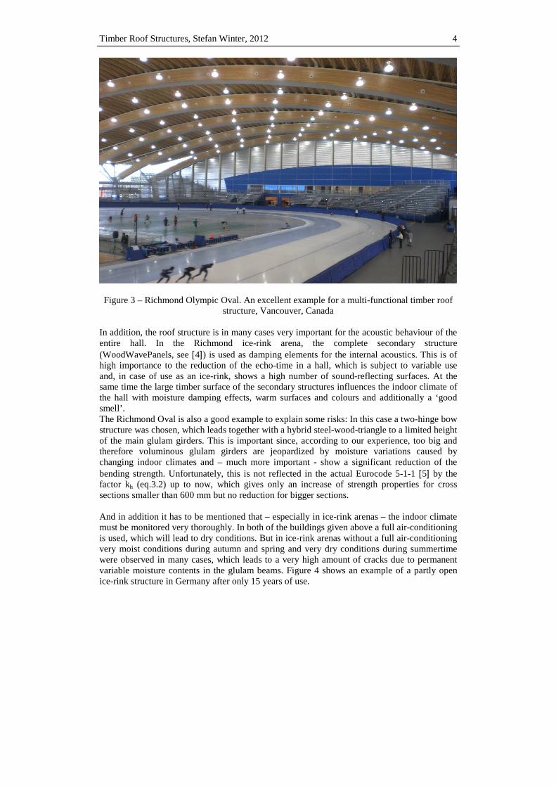
structure, Vancouver, Canada In addition, the roof structure is in many cases very important for the acoustic behaviour of the entire hall. In the Richmond ice-rink arena, the complete secondary structure (WoodWavePanels, see [4]) is used as damping elements for the internal acoustics. This is of high importance to the reduction of the echo-time in a hall, which is subject to variable use and, in case of use as an ice-rink, shows a high number of sound-reflecting surfaces. At the same time the large timber surface of the secondary structures influences the indoor climate of the hall with moisture damping effects, warm surfaces and colours and additionally a ‘good smell’. The Richmond Oval is also a good example to explain some risks: In this case a two-hinge bow structure was chosen, which leads together with a hybrid steel-wood-triangle to a limited height of the main glulam girders. This is important since, according to our experience, too big and therefore voluminous glulam girders are jeopardized by moisture variations caused by changing indoor climates and – much more important - show a significant reduction of the bending strength. Unfortunately, this is not reflected in the actual Eurocode 5-1-1 [5] by the factor kh (eq.3.2) up to now, which gives only an increase of strength properties for cross sections smaller than 600 mm but no reduction for bigger sections. And in addition it has to be mentioned that – especially in ice-rink arenas – the indoor climate must be monitored very thoroughly. In both of the buildings given above a full air-conditioning is used, which will lead to dry conditions. But in ice-rink arenas without a full air-conditioning very moist conditions during autumn and spring and very dry conditions during summertime were observed in many cases, which leads to a very high amount of cracks due to permanent variable moisture contents in the glulam beams. Figure 4 shows an example of a partly open ice-rink structure in Germany after only 15 years of use.
Stefan Winter 5
(a) (b)
Figure 4 – Structure under varying moisture conditions; (a) Typical defrost water in autumn
during ice preparation; (b) Unacceptable amount of cracks.
It has to be noticed that very dry conditions (e.g. in heated premises during long cold temperature periods) may also cause unacceptable cracks especially in curved beams with regular tension stresses perpendicular to the grain. Reinforcement e.g. by glued-in-rods is therefore highly recommended in these cases. But in principle the very high number of timber roof structure combined with the very small amount of damages demonstrates that well designed timber structures are very sustainable solutions if they are used in adequate (climatic) conditions. Some more hints about robustness and learning by mistakes can be found in clauses 2.4 and 2.5.
2.3. Secondary Structures – new developments
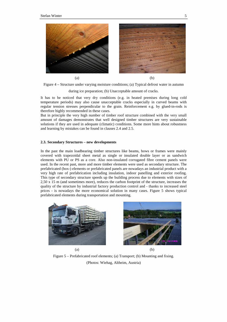
In the past the main loadbearing timber structures like beams, bows or frames were mainly covered with trapezoidal sheet metal as single or insulated double layer or as sandwich elements with PU or PS as a core. Also non-insulated corrugated fibre cement panels were used. In the recent past, more and more timber elements were used as secondary structure. The prefabricated (box-) elements or prefabricated panels are nowadays an industrial product with a very high rate of prefabrication including insulation, indoor panelling and exterior roofing. This type of secondary structure speeds up the building process due to elements with sizes of 2,50 x 15 m (and sometimes more), reduces the carbon footprint of the structure, increases the quality of the structure by industrial factory production control and - thanks to increased steel prices - is nowadays the more economical solution in many cases. Figure 5 shows typical prefabricated elements during transportation and mounting.
(a) (b)
Figure 5 – Prefabricated roof elements; (a) Transport; (b) Mounting and fixing.
(Photos: Wiehag, Altheim, Austria)
Timber Roof Structures, Stefan Winter, 2012
Figure 5 shows a typical erection of an industrial hall in Austria with a roof area of 24.400 mMounting of more than 1.200 msystems like this! But another topic has to be observed: timber elements in Austria, more limiting fire safety regulations exist in other European countries. E.g. in Germany combustible roof sections are limited to 2.500 mpossible but it has to be verified, that the fire spread along (and in) these roof structures is restricted. But European test stastill missing today and the actual German test standard DIN 18234for steel roof structures. Therefore additional researchcommon construction rules to fultrial tests were performed several years ago and showed, thatby using simple constructive solutions and in some cases gypsum boards as an additional fiprotection. Figure 6 shows The lower panel was out of 15of two OSB-panels, but in the determined. The results wereelements, further developments are necessary. In further addition to fire safetyCentral Europe and in the Nordic countries very high requiremenot only due to regulations but also and less are not unusual, leading to insulation thicknesses of 400 mm and more. In combination with enormous sizes of the roofspractice. The results are fully insulated roof elements with exterior ‘vapourlayers (e.g. PVC width), sometimes in combination with a greenA typical and also extreme example of such a project is the new factory of the company SMASolar Technologie AG in Kassel, a photsize of 140 x 180 m2 and represents only the first sector of finally 4 similar halls. Figure 7 shows the new hall at the beginning of 2012.
(a)
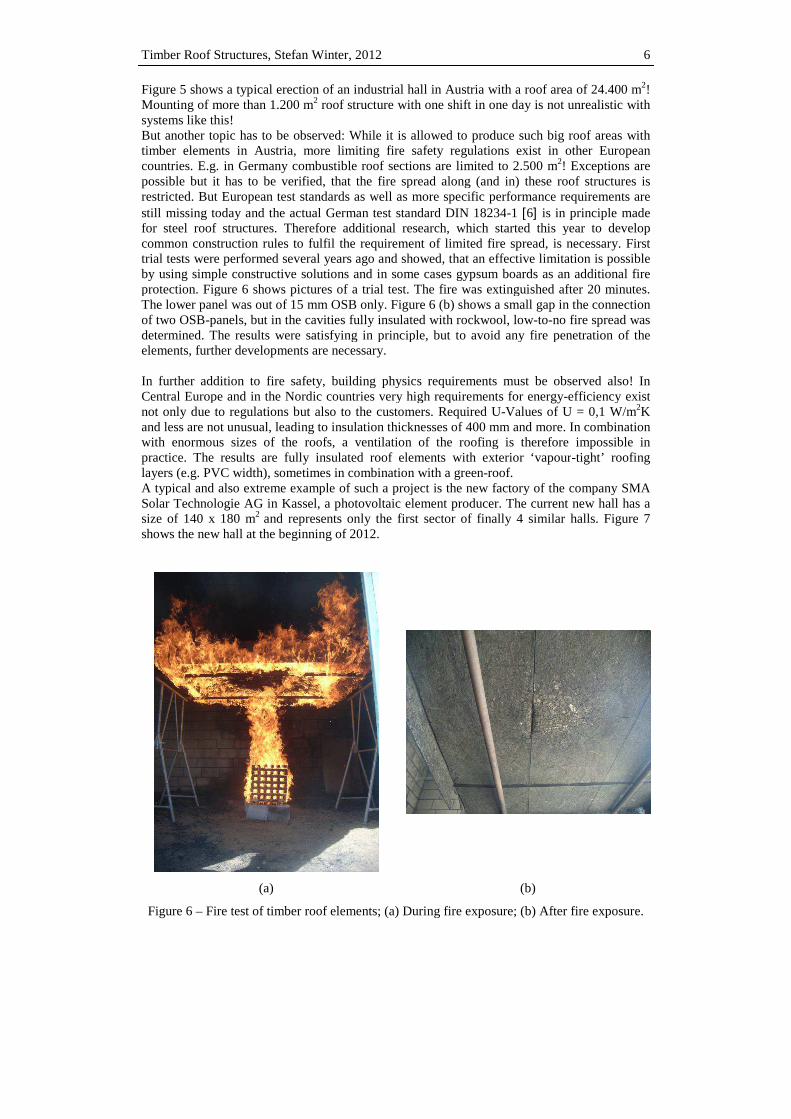
Figure 6 – Fire test of timber roof elements; (a) During fire exposure; (b) After fire exposure.
Timber Roof Structures, Stefan Winter, 2012
typical erection of an industrial hall in Austria with a roof area of 24.400 mMounting of more than 1.200 m2 roof structure with one shift in one day is not unrealistic with
has to be observed: While it is allowed to produce such big roof areas with timber elements in Austria, more limiting fire safety regulations exist in other European countries. E.g. in Germany combustible roof sections are limited to 2.500 m2! Exceptions are
be verified, that the fire spread along (and in) these roof structures is restricted. But European test standards as well as more specific performance requirements are still missing today and the actual German test standard DIN 18234-1 [6] is in principlefor steel roof structures. Therefore additional research, which started this year to develop common construction rules to fulfil the requirement of limited fire spread, is necessarytrial tests were performed several years ago and showed, that an effective limitation is possible by using simple constructive solutions and in some cases gypsum boards as an additional fiprotection. Figure 6 shows pictures of a trial test. The fire was extinguished after 20 minutes.
he lower panel was out of 15 mm OSB only. Figure 6 (b) shows a small gap in the connection panels, but in the cavities fully insulated with rockwool, low-to-no fire spread was The results were satisfying in principle, but to avoid any fire penetration of the
ements, further developments are necessary.
In further addition to fire safety, building physics requirements must be observedEurope and in the Nordic countries very high requirements for energy-efficiency exist
regulations but also to the customers. Required U-Values of U = 0,1 W/mand less are not unusual, leading to insulation thicknesses of 400 mm and more. In combination with enormous sizes of the roofs, a ventilation of the roofing is therefore
fully insulated roof elements with exterior ‘vapour-width), sometimes in combination with a green-roof.
A typical and also extreme example of such a project is the new factory of the company SMASolar Technologie AG in Kassel, a photovoltaic element producer. The current
and represents only the first sector of finally 4 similar halls. Figure 7 shows the new hall at the beginning of 2012.
(b)
Fire test of timber roof elements; (a) During fire exposure; (b) After fire exposure.
6
typical erection of an industrial hall in Austria with a roof area of 24.400 m2! roof structure with one shift in one day is not unrealistic with
produce such big roof areas with timber elements in Austria, more limiting fire safety regulations exist in other European
! Exceptions are be verified, that the fire spread along (and in) these roof structures is
performance requirements are is in principle made
which started this year to develop is necessary. First
an effective limitation is possible by using simple constructive solutions and in some cases gypsum boards as an additional fire
s extinguished after 20 minutes. ap in the connection
no fire spread was satisfying in principle, but to avoid any fire penetration of the
building physics requirements must be observed also! In efficiency exist
Values of U = 0,1 W/m2K and less are not unusual, leading to insulation thicknesses of 400 mm and more. In combination
a ventilation of the roofing is therefore impossible in -tight’ roofing
A typical and also extreme example of such a project is the new factory of the company SMA new hall has a
and represents only the first sector of finally 4 similar halls. Figure 7
Fire test of timber roof elements; (a) During fire exposure; (b) After fire exposure.

Stefan Winter
Figure 7 – The first new hall of SMA Solar Technologie AG in Kassel, Germany; The principle roof element structure is given in Figure 8. The insulation thickness is 360 mm, realized with cellulose fibre. Of course the fire performance was a subject of special approvals but also the building physicinsulated roof were and still are subject of
Figure 8 –Typical roof element of new hall of SMA AG in Kassel, Germany;
As no ventilation is intendedthe sheds are covered with photovoltaic elementscalculated with the dynamic moisture calculation software WUFIformer and current research projects, wide simulation experienceairtightness concept, some subject of moisture monitoring by the timber test laboratory of MPABau, TU now the results are following the calculated numbersgiven in a presentation at Auckland [8].
The first new hall of SMA Solar Technologie AG in Kassel, Germany;
principle roof element structure is given in Figure 8. The insulation thickness is 360 mm, realized with cellulose fibre. Of course the fire performance was a subject of special approvals but also the building physical behaviour and here especially the moisture behavio
f were and still are subject of special research.
Typical roof element of new hall of SMA AG in Kassel, Germany;
(SGHG Architects, Erfurt, Germany)
intended, the roof shall be covered with a green roof in the flat areas and the sheds are covered with photovoltaic elements. The moisture behaviour of the elements was calculated with the dynamic moisture calculation software WUFI [7]. Despite experience
research projects, wide simulation experiences and a very diligent some uncertainties remain. Therefore, several roof sections are now
subject of moisture monitoring by the timber test laboratory of MPABau, TU Munich. Up to now the results are following the calculated numbers (Figure 9). A brief description will be given in a presentation at the World Conference of Timber Engineering (WCTE 2012) in
7
The first new hall of SMA Solar Technologie AG in Kassel, Germany;
principle roof element structure is given in Figure 8. The insulation thickness is 360 mm, realized with cellulose fibre. Of course the fire performance was a subject of special approvals
sture behaviour of the fully
Typical roof element of new hall of SMA AG in Kassel, Germany;
in the flat areas and r of the elements was
Despite experiences in and a very diligent
several roof sections are now Munich. Up to
. A brief description will be World Conference of Timber Engineering (WCTE 2012) in

Timber Roof Structures, Stefan Winter, 2012 8
Final remark: The air tightness test with a Blower-Door test showed a q50-value of only 0,08/h! Of course this must be related to the extreme A/V-value of this building, but it demonstrates that, based on an exact planning process and very good prefabrication (in this case in a field factory close to the site), excellent energy-efficiency can also be guaranteed for industrial buildings when using timber elements!
2.4. Robustness
Some short remarks about robustness - a design item, which is unfortunately not observed in many cases. After the disastrous roof collapse of the Bad Reichenhall ice-rink arena roof, many investigations were done in Germany and the neighbouring countries. Some of the results are presented also in clause 2.5. But a special look should be taken at robustness. Figure 10 shows one of the main principles of robust design: If there is a damage of one of the primary members, the secondary structure should not be able to transfer the additional loads to the neighbouring girders because this will immediately cause an overload of these beams and a progressive collapse is the result. This was observed e.g. in Bad Reichenhall. Of course in some cases this design criteria leads to different and sometimes opposing results: To enable a single collapse of a main girder the purlins shall be single span beams, but to avoid down falling of a destroyed purlin, a continuous supporting system of the purlins may be required. In conjunction with the chosen system and especially with probable further load combinations, special risk analysis may help to find adequate solutions.
Figure 9 - Comparison of data and WUFI® simulation results of climate conditions between the top OSB panel and the cellulose insulation with adjusted moisture content of the initial
cellulose insulation [8].
-140
-120
-100
-80
-60
-40
-20
0
20
40
60
80
100
-20
-10
0
10
20
30
40
50
60
rela
tive
hum
idity
[%
]
tem
pera
ture
[°C
]
measured data of temperature below top OSBWUFI data, temperature below top OSB, initial m.c. cellulose = 1/3/6 kg/m³measured data of relative humidity below top OSBWUFI data, relative humidity below top OSB, initial m.c. cellulose = 1 kg/m³WUFI data, relative humidity below top OSB, initial m.c. cellulose = 3 kg/m³WUFI data, relative humidity below top OSB, initial m.c. cellulose = 6 kg/m³

Stefan Winter
(a)
Figure 100 – Collapse of a ‘robust’ system
2.5. Learning from mistakes
As mentioned before, after the Bad Reichenhall collapse inspected, to avoid further collapses. Construction at the Technische Universität München conducted a largethe structural reliability of all 152 wideCity of Munich. The results were later combined with investigations of other regions in Germany, which showed the same tendency as given below. Figuassessment of the Munich wide span timber structures.
(a)
Figure 11 – Results of Munich assessment
(b)
Collapse of a ‘robust’ system; (a) Main girder collapse; (b) No progressive collapse
mistakes
As mentioned before, after the Bad Reichenhall collapse a lot of existing structures wereinspected, to avoid further collapses. The Chair of Timber Structures and Building Construction at the Technische Universität München conducted a large-scale project the structural reliability of all 152 wide-span timber structures under the responsibility of the City of Munich. The results were later combined with investigations of other regions in Germany, which showed the same tendency as given below. Figure 11 shows the results of the assessment of the Munich wide span timber structures.
(b)
Results of Munich assessment; (a) Causes of failure; (b) Accountability for f
9
No progressive
a lot of existing structures were The Chair of Timber Structures and Building
scale project to assess span timber structures under the responsibility of the
City of Munich. The results were later combined with investigations of other regions in re 11 shows the results of the
Accountability for failure.
Timber Roof Structures, Stefan Winter, 2012 10
It can be concluded that failures connected to human error represent the vast majority of classified cases. Another large and detailed analysis of failed timber structures in Germany by Blaß and Frese [1] and a Nordic project by Frühwald et al. [9] both come to a similar conclusion.
Human error is virtually always connected to knowledge and quality of work. To decrease errors and the occurrence of failures, it has proven to be very beneficial to introduce guidelines and schedules for assessing and inspecting a structure. The building book, accompanying a structure over its lifetime, customizes these and is therefore a good resource to accomplish abovementioned objectives for each individual structure.
Or in other words: It’s not enough to deliver a perfect design and a structure of high quality – we have to work on a more Life Cycle based design and maintenance of the structures. As especially timber structures are sensitive against climate based moisture changes, a regular monitoring is highly recommended!
3. REFERENCES
[1] Blass, H.-J., Frese, M., Failure Analysis on Timber Structures in Germany - A Contri-
bution to COST Action E55, COST Action E55, Graz University of Technology, 2007. [2] DIN 68800-1:2011-10 Wood-preservation – General Principles. German Standard,
DIN, Berlin, March 2012 [3] DIN 68800-2:2012-02 Wood preservation – Preventive constructional measures in
buildings. German Standard, DIN, Berlin, March 2012 [4] Information brochure about Richmond Olympic Oval,
www.naturallywood.com/sites/default/files/Richmond-Olympic-Oval-Case-Study.pdf [5] EN 1995-1-1:2010-12, Eurocode 5: Design of timber structures - Part 1-1: General -
Common rules and rules for buildings. European Standard, CEN, Brussels, November 2010.
[6] DIN 18234-1:2003-09, Fire safety of large roofs for buildings; fire exposure from below Part 1: Definitions, requirements and tests; roof areas without openings
[7] WUFI Pro, Version 5, Fraunhofer Institut für Bauphysik, Holzkirchen, Stuttgart, Germany
[8] Schulte-Wrede,M.; Merk,M.; Gamper,A.; Winter,S.; Wolf,A.: Hygrothermal behaviour of a large scale wooden flat roof structure in Central Europe. WCTE 2012, Auckland
[9] Frühwald, E., Serrano, E., Toratti, T., Emilsson, A., Thelandersson, S., Design of safe Timber Structures – How can we learn from Structural Failures in Concrete, Steel and Timber?, Report TVBK-3053., Div. of Struct. Eng., Lund University, 2007, p. 270