Embed Size (px)
Citation preview
1
T.Y. Diploma : Sem. VI [ME/MH/MI]
Design of Machine Elements Time : 4 Hrs. Prelim Question Paper Solution Marks : 100
Q.1(a) Attempt any THREE of the following [12]Q.1(a) (i) What are the steps involved in General Design Procedure ? Explain. [4](A) In designing a machine component, there is no rigid rule. The problem may be attempted in several
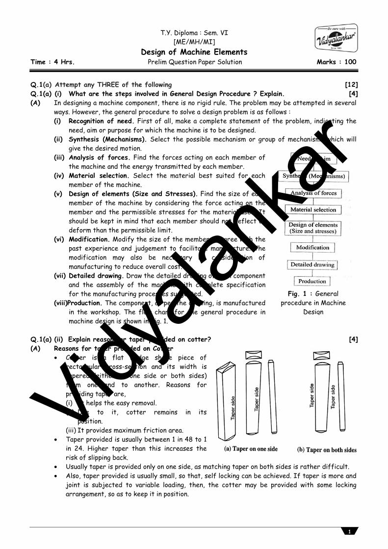
ways. However, the general procedure to solve a design problem is as follows : (i) Recognition of need. First of all, make a complete statement of the problem, indicating the
need, aim or purpose for which the machine is to be designed. (ii) Synthesis (Mechanisms). Select the possible mechanism or group of mechanisms which will
give the desired motion. (iii) Analysis of forces. Find the forces acting on each member of
the machine and the energy transmitted by each member. (iv) Material selection. Select the material best suited for each
member of the machine. (v) Design of elements (Size and Stresses). Find the size of each
member of the machine by considering the force acting on the member and the permissible stresses for the material used. It should be kept in mind that each member should not deflect or deform than the permissible limit.
(vi) Modification. Modify the size of the member to agree with the past experience and judgement to facilitate manufacture. The modification may also be necessary by consideration of manufacturing to reduce overall cost.
(vii) Detailed drawing. Draw the detailed drawing of each component and the assembly of the machine with complete specification for the manufacturing processes suggested.
(viii)Production. The component, as per the drawing, is manufactured in the workshop. The flow chart for the general procedure in machine design is shown in Fig. 1.
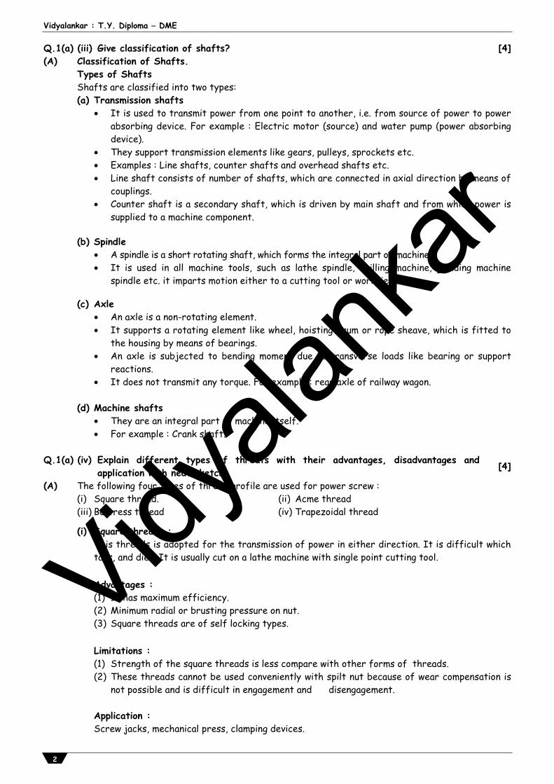
Q.1(a) (ii) Explain reason for taper provided on cotter? [4](A) Reasons for taper provided on Cotter
Cotter is a flat wedge shape piece of rectangular cross-section and its width is tapered (either on one side or both sides) from one end to another. Reasons for providing taper are,
(i) It helps the easy removal. (ii) Due to it, cotter remains in its
position. (iii) It provides maximum friction area.
Taper provided is usually between 1 in 48 to 1 in 24. Higher taper than this increases the risk of slipping back.
Usually taper is provided only on one side, as matching taper on both sides is rather difficult. Also, taper provided is usually small, so that, self locking can be achieved. If taper is more and
joint is subjected to variable loading, then, the cotter may be provided with some locking arrangement, so as to keep it in position.
Fig. 1 : General procedure in Machine
Design
Vidyala
nkar
Vidyalankar : T.Y. Diploma DME
2
Q.1(a) (iii) Give classification of shafts? [4](A) Classification of Shafts. Types of Shafts Shafts are classified into two types:
(a) Transmission shafts It is used to transmit power from one point to another, i.e. from source of power to power
absorbing device. For example : Electric motor (source) and water pump (power absorbing device).
They support transmission elements like gears, pulleys, sprockets etc. Examples : Line shafts, counter shafts and overhead shafts etc. Line shaft consists of number of shafts, which are connected in axial direction by means of
couplings. Counter shaft is a secondary shaft, which is driven by main shaft and from which power is
supplied to a machine component. (b) Spindle A spindle is a short rotating shaft, which forms the integral part of machine. It is used in all machine tools, such as lathe spindle, drilling machine, grinding machine
spindle etc. it imparts motion either to a cutting tool or workpiece. (c) Axle An axle is a non-rotating element. It supports a rotating element like wheel, hoisting drum or rope sheave, which is fitted to
the housing by means of bearings. An axle is subjected to bending moment due to transverse loads like bearing or support
reactions. It does not transmit any torque. For example : rear axle of railway wagon. (d) Machine shafts They are an integral part of machine itself. For example : Crank shaft.
Q.1(a) (iv) Explain different types of threats with their advantages, disadvantages and
application with neat sketch. [4]
(A) The following four types of thread profile are used for power screw : (i) Square thread. (ii) Acme thread (iii) Buttress thread (iv) Trapezoidal thread
(i) Square threads : This threads is adopted for the transmission of power in either direction. It is difficult which
taps, and dies. It is usually cut on a lathe machine with single point cutting tool.
Advantages : (1) It has maximum efficiency. (2) Minimum radial or brusting pressure on nut. (3) Square threads are of self locking types. Limitations : (1) Strength of the square threads is less compare with other forms of threads. (2) These threads cannot be used conveniently with spilt nut because of wear compensation is
not possible and is difficult in engagement and disengagement. Application : Screw jacks, mechanical press, clamping devices.
Vidyala
nkar
Prelim Question Paper Solution
3
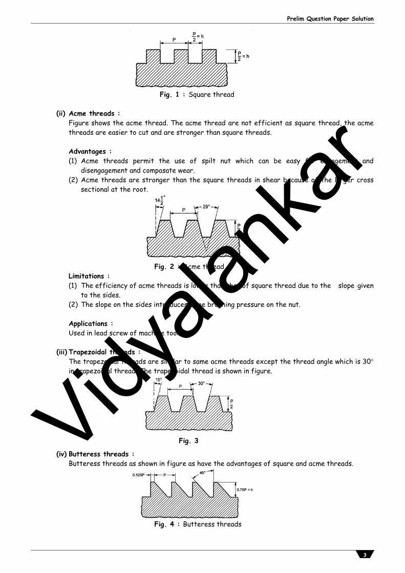
Fig. 1 : Square thread
(ii) Acme threads : Figure shows the acme thread. The acme thread are not efficient as square thread, the acme
threads are easier to cut and are stronger than square threads.
Advantages : (1) Acme threads permit the use of spilt nut which can be easy for engagement and
disengagement and compasate wear. (2) Acme threads are stronger than the square threads in shear because of the larger cross
sectional at the root.
Fig. 2 : Acme thread
Limitations : (1) The efficiency of acme threads is lower than that of square thread due to the slope given
to the sides. (2) The slope on the sides introduces some brushing pressure on the nut. Applications : Used in lead screw of machine tools.
(iii) Trapezoidal threads : The trapezoidal threads are similar to same acme threads except the thread angle which is 30
in trapezoidal thread. The trapezoidal thread is shown in figure.
Fig. 3
(iv) Butteress threads : Butteress threads as shown in figure as have the advantages of square and acme threads.
Fig. 4 : Butteress threads
Vidyala
nkar
Vidyalankar : T.Y. Diploma DME
4
Limitation : These are used where force or power is required to be transmitted only in one direction.
Advantages : (i) The higher efficiency (ii) The ease of cutting (iii) The adoptability to a split nut (iv) These threads are stronger in shear than any other power thread because of the greater
thickness at the root base of the thread.
Application : These threads are used in vices and screw jack where force is applied in undirection.
Q.1(b) Attempt any ONE of the following [6]Q.1(b) (i) Explain creep and creep curve. [6](A) “When a component is subjected to constant stress at high temperature over a long period of
time, it will undergo a slow and permanent deformation called creep”. Creep is defined as ‘slow and progressive deformation of material with time under constant
stress’. Creep is function of stress and temperature and becomes important for component operating a
elevated temperature. For example : Bolts and pipes in thermal power plant.
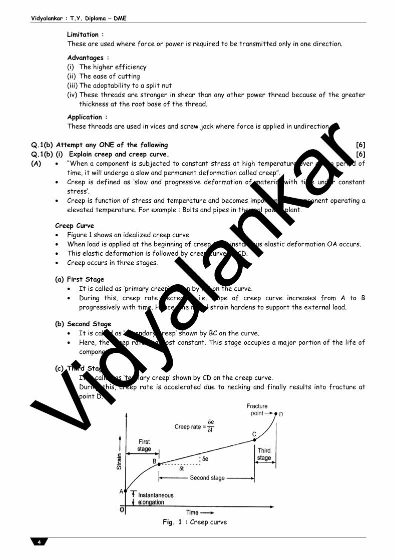
Creep Curve Figure 1 shows an idealized creep curve When load is applied at the beginning of creep test, instaneous elastic deformation OA occurs. This elastic deformation is followed by creep curve ABCD. Creep occurs in three stages.
(a) First Stage It is called as ‘primary creep’ shown by AB on the curve. During this, creep rate decreases i.e. slope of creep curve increases from A to B
progressively with time. Hence, the metal strain hardens to support the external load. (b) Second Stage It is called as ‘secondary creep’ shown by BC on the curve. Here, the creep rate is almost constant. This stage occupies a major portion of the life of
component. (c) Third Stage It is called as ‘tertiary creep’ shown by CD on the creep curve. During this, creep rate is accelerated due to necking and finally results into fracture at
point D.
Fig. 1 : Creep curve
Vidyala
nkar
Prelim Question Paper Solution
5
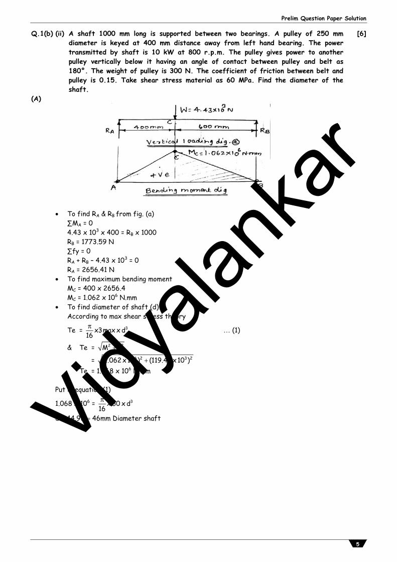
Q.1(b) (ii) A shaft 1000 mm long is supported between two bearings. A pulley of 250 mm diameter is keyed at 400 mm distance away from left hand bearing. The power transmitted by shaft is 10 kW at 800 r.p.m. The pulley gives power to another pulley vertically below it having an angle of contact between pulley and belt as 180°. The weight of pulley is 300 N. The coefficient of friction between belt and pulley is 0.15. Take shear stress material as 60 MPa. Find the diameter of the shaft.
[6]
(A)
To find RA & RB from fig. (a) ∑MA = 0 4.43 x 103 x 400 = RB x 1000 RB = 1773.59 N ∑fy = 0 RA + RB – 4.43 x 103 = 0 RA = 2656.41 N To find maximum bending moment
MC = 400 x 2656.4 MC = 1.062 x 10⁶ N.mm
To find diameter of shaft (d) According to max shear stress theory
Te = 3x3max x d16 (1)
& Te = 2 2M t
= 6 2 3 2(1.062 x10 ) (119.42 x10 ) Te = 1.068 x 10⁶ N.mm Put in equation (1)
1.068 x 106 = 3x 60 x d16
d = 44.93 46mm Diameter shaft
Vidyala
nkar
Vidyalankar : T.Y. Diploma DME
6
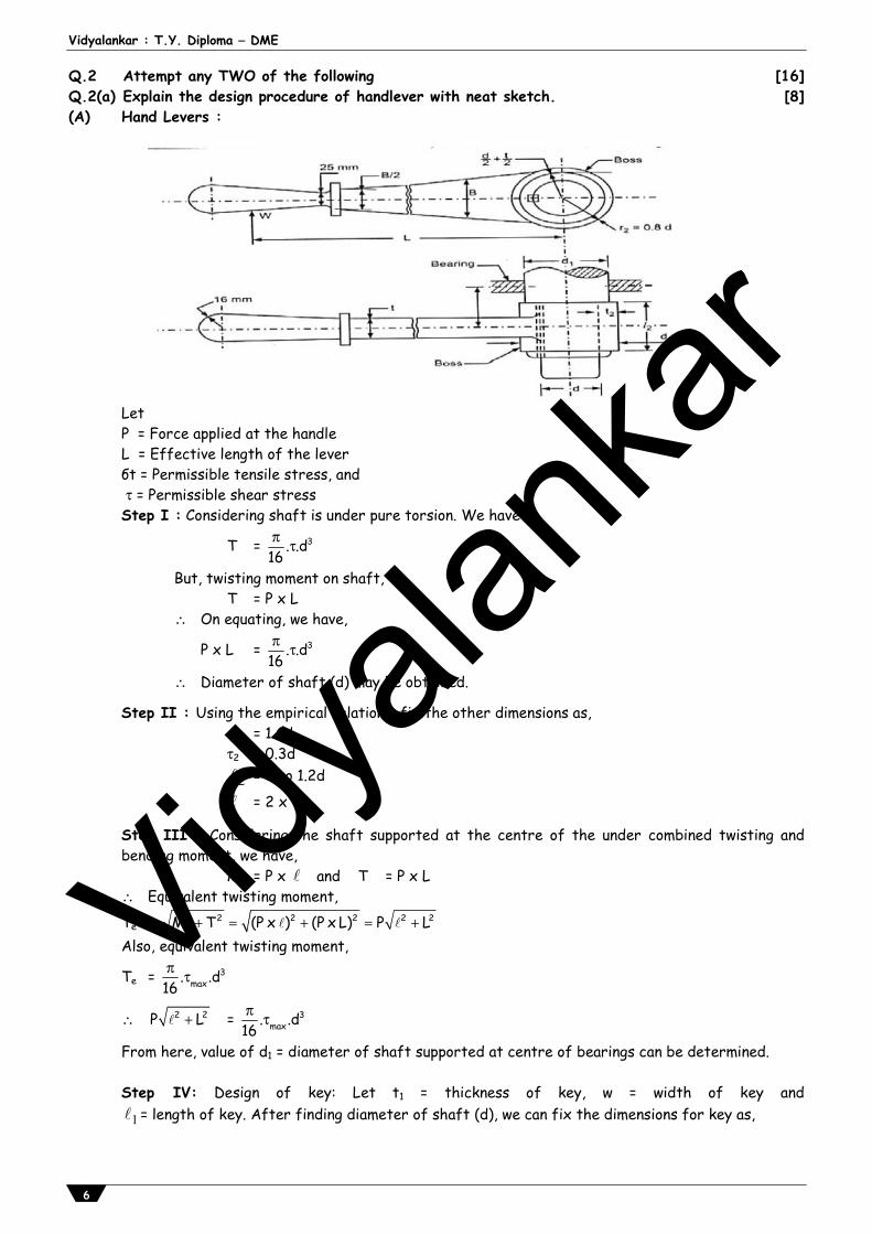
Q.2 Attempt any TWO of the following [16]Q.2(a) Explain the design procedure of handlever with neat sketch. [8](A) Hand Levers :
Let P = Force applied at the handle L = Effective length of the lever бt = Permissible tensile stress, and = Permissible shear stress Step I : Considering shaft is under pure torsion. We have
T = 3. .d16
But, twisting moment on shaft, T = P x L
On equating, we have,
P x L = 3. .d16
Diameter of shaft (d) may be obtained.
Step II : Using the empirical relations, fix the other dimensions as, d2 = 1.6d 2 = 0.3d
2 = d to 1.2d
= 2 x 2
Step III : Considering the shaft supported at the centre of the under combined twisting and bending moment, we have,
M = P x and T = P x L Equivalent twisting moment,
Te = 2 2 2 2 2 2M T (P x ) (P x L) P L Also, equivalent twisting moment,
Te = 3max. .d
16
2 2P L = 3max. .d
16
From here, value of d1 = diameter of shaft supported at centre of bearings can be determined. Step IV: Design of key: Let t1 = thickness of key, w = width of key and
1 = length of key. After finding diameter of shaft (d), we can fix the dimensions for key as,
Vidyala
nkar
Prelim Question Paper Solution
7
w = 1d dand t4 6
Considering shear failure of key,
We have, T = (w. 1 .) x d2
Length 1 can be determined.
Also, length 1 may be taken as length of boss i.e. 2 . Step V : Considering bending failure of lever, we can determine the cross-section of lever near the boss. Let t = thickness of lever near the boss and B = width of height of lever near the boss. We have, Bending moment on the lever = M = P x (L – rb)
and Section modulus = Z = 21 .t.B6
where rb = Radius of boss = 2d2
Bending stress, σb = MZ
= b
2
P.(L r )1 .tB6
Width of lever may be taken as, B = 4t to 5t. From this equation, values of t and B can be determined.
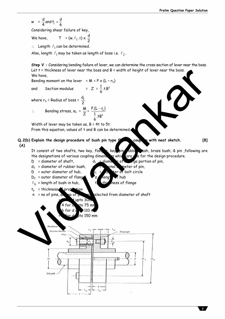
Q.2(b) Explain the design procedure of bush pin type flexible coupling with neat sketch. [8](A)
It consist of two shafts, two key, flanges, key, pin, rubber bush, brass bush, & pin ,following are the designations of various coupling dimensions which are use for the design procedure. D = diameter of shaft, d1 = diameter of enlarge portion of pin, d2 = diameter of rubber bush, db = nominal diameter of pin, D = outer diameter of hub, D1 = diameter of bolt circle D2 = outer diameter of flange, z = length of hub
b = length of bush in hub, tf = thickness of flange tp = thickness of protection n = no of pins, and no of pins are selected from diameter of shaft = 3 for d upto 30mm
= 4 for d upto 75 mm = 6 for d upto 110 mm = 8 for d upto 150 mm
Vidyala
nkar
Vidyalankar : T.Y. Diploma DME
8
Step no 1: Design of shaft (d) Considering maximum shear stress,
T = 3maxx x d
16 (a)
Step no 2: Design of key Fix the dimension of key from the standard shaft diameter, and as per the requirement square or rectangular key can be selected, w = width of key t = thickness of key lk = length of key = 1.5dby proportion (1) 1. For Square key, w = t = d/4 (b) 2. For rectangular key, w = d/4 & t = 2/3w (c) 3. & length of key can be obtained by shearing and crushing failure of key. Considering shearing of key, T = k x w x lk x d/2 (2) Considering crushing failure of key, T = σc x lk x d/2 x t/2 (3) Consider maximum value of length of key from equation 1, 2, 3 Step no 3: Design of hub 1. D = outer diameter of hub D = 2d 2. = length of hub =1.5d 3. Torsional shear stress in the hub can be calculated from below equation,
T = 4hx x (1 k )
16
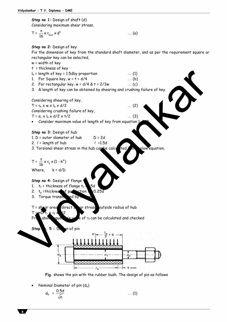
Where, k = d/D Step no 4: Design of flange 1. tf = thickness of flange tf =0.5d 2. tp =thickness of protection tp =0.25d 3. Torque transmitted by flange T = shear area × direct shear stress× outside radius of hub T = πD tr x f xD/2 From above equation’s value of f can be calculated and checked Step no. 5 : Design of pin
Fig. shows the pin with the rubber bush. The design of pin as follows
Nominal Diameter of pin (db)
db = 0.5dn
(1)
Vidyala
nkar
Prelim Question Paper Solution
9
Diameter of enlarge portion of pin (d1) d1 = db + 4 (2) Outer Diameter of rubber bush (d2)
Assume that brass brush 2mm thickness & rubber bush 4mm thickness are fitted d2 = d1 + (2 x 2) + (2 x 6) (3) Diameter of bolt in the circle (D6) D1 = D + d2 + (2 x 8) (4) Length of bush in the flange ( b ) Considering bearing pressure or pin F = Pb x d2 x b & Torque Transmitted, T = n x F x D1/2 T = n x Pb x d2 x b x D1/2 (5)
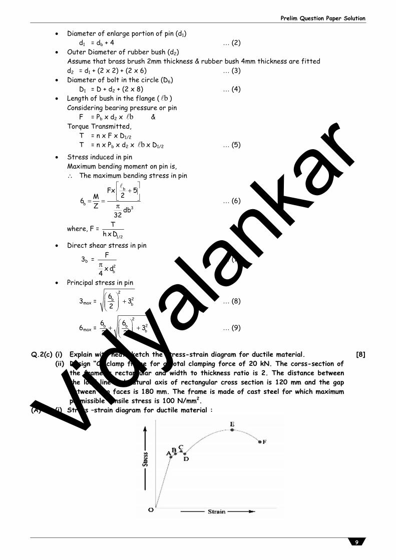
Stress induced in pin Maximum bending moment on pin is, The maximum bending stress in pin
b
b3
Fx 52M6
Z db32
(6)
where, F = 1/2
Th xD
Direct shear stress in pin
3b = 2b
F
x d4
(7)
Principal stress in pin
3max = 2
2bb
63
2
(8)
6max = 2
2b bb
6 63
2 2
(9)
Q.2(c) (i) Explain with neat sketch the stress-strain diagram for ductile material.
(ii) Design “C” clamp frame for a total clamping force of 20 kN. The corss-section ofthe frame is rectangular and width to thickness ratio is 2. The distance betweenthe load line and natural axis of rectangular cross section is 120 mm and the gapbetween two faces is 180 mm. The frame is made of cast steel for which maximumpermissible tensile stress is 100 N/mm2.
[8]
(A) (i) Stress –strain diagram for ductile material :
Vidyala
nkar
Vidyalankar : T.Y. Diploma DME
10
Point A : Proportional limit Point B : Elastic limit Point c : Upper yield point Point D : Lower yield point Point E : Ultimate tensile stress point Point F : Breaking Stress point.
1. Proportional limit : We see from the diagram that from point O to A is a straight line, which represents that the stress is proportional to strain. Beyond point A, the curve slightly deviates from the straight line. It is thus obvious, that Hooke's law holds good up to point A and it is known as proportional limit. It is defined as that stress at which the stress-strain curve begins to deviate from the straight line.
2. Elastic limit : It may be noted that even if the load is increased beyond point A upto the point B, the material will regain its shape and size when the load is removed. This means that the material has elastic properties up to the point B. This point is known as elastic limit. It is defined as the stress developed in the material without any permanent set.
3. Yield point : If the material is stressed beyond point B, the plastic stage will reach i.e. on the load, the material will not be able to recover its original size and shape. A little consideration will show that beyond point B, the strain increases at a faster rate with any increase in the stress until the point C is reached. At this point, the material yields before the load and there is an appreciable strain without any increase in stress. In case of mild steel, it will be seen that a small load drops to D, immediately after yielding commences. Hence there are two yield points C and D. The points C and D are called the upper and lower yield points respectively. The stress corresponding to yield point is known as yield point stress.
4. Ultimate stress : At D, the specimen regains some strength and higher values of stresses are required for higher strains, than those between A and D. The stress (or load) goes on increasing till the point E is reached. The gradual increase in the strain (or length) of the specimen is followed with the uniform reduction of its cross-sectional area. The work done, during stretching the specimen, is transformed largely into heat and the specimen becomes hot. At E, the stress, which attains its maximum value is known as ultimate stress. It is defined as the largest stress obtained by dividing the largest value of the load reached in a test to the original cross-sectional area of the test piece.
5. Breaking stress : After the specimen has reached the ultimate stress, a neck is formed, which decreases the cross-sectional area of the specimen, as shown in Fig. The stress is, therefore, reduced until the specimen breaks away at point F. The stress corresponding to point F is known as breaking stress.
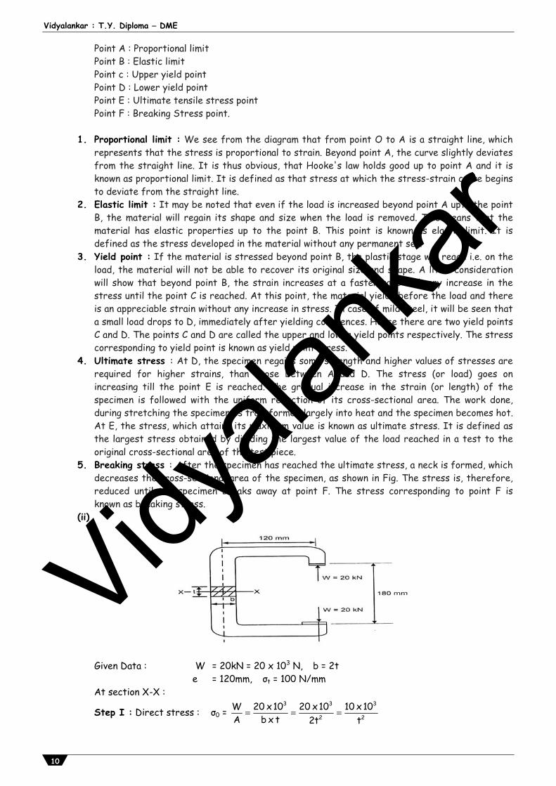
(ii)
Given Data : W = 20kN = 20 x 103 N, b = 2t e = 120mm, σt = 100 N/mm
At section X-X :
Step I : Direct stress : σ0 = 3 3 3
2 2W 20 x10 20 x10 10 x10A b x t 2t t
Vidyala
nkar
Prelim Question Paper Solution
11
Step II : Bending stress : σb = 2
M W x eZ 1 tb
6
σb = 3 6
2 320 x10 x120 x 6 3.6x10
t x (2t) t
Step III : Resultant stress : σtR = σ0 + σb
3 6
2 310 x10 3.6x10
t t = 100
3 6
310 x10 t 3.6 10
t = 100
10 x 103t + 3.6 x 106 = 100t3 100t3 – 10 x 103t = 3.6 x 10⁶ Divide the equation by 100,
t3 – 100t = 3.6 x 10⁴; Using trial and error t = 34mm & b = 2t = 2 x 34 = 68mm
Q.3 Attempt any FOUR of the following [16]Q.3(a) Write down the names of any four theories of elastic failure. [4](A) Theories of elastic failure (i) Maximum principal stress theory (Rankine's theory) (ii) Maximum shear stress theory (Tresca & Guest theory) (iii) Maximum strain energy theory (Haigh's theory)
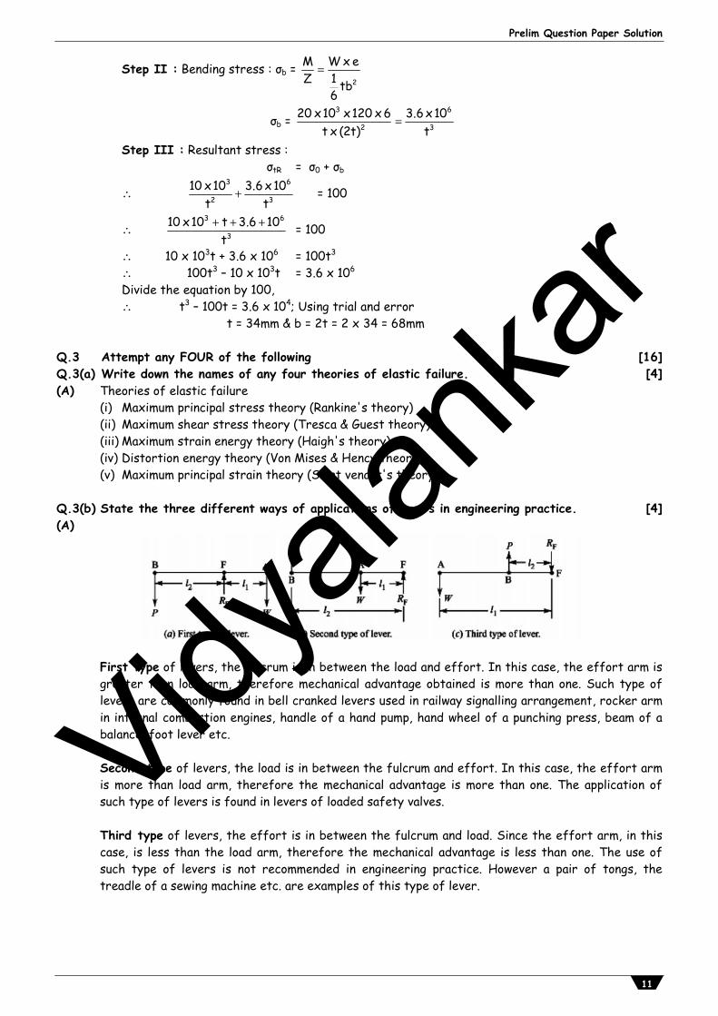
(iv) Distortion energy theory (Von Mises & Hency theory) (v) Maximum principal strain theory (Saint venant's theory) Q.3(b) State the three different ways of applications of levers in engineering practice. [4](A)
First type of levers, the fulcrum is in between the load and effort. In this case, the effort arm is greater than load arm, therefore mechanical advantage obtained is more than one. Such type of levers are commonly found in bell cranked levers used in railway signalling arrangement, rocker arm in internal combustion engines, handle of a hand pump, hand wheel of a punching press, beam of a balance, foot lever etc. Second type of levers, the load is in between the fulcrum and effort. In this case, the effort arm is more than load arm, therefore the mechanical advantage is more than one. The application of such type of levers is found in levers of loaded safety valves. Third type of levers, the effort is in between the fulcrum and load. Since the effort arm, in this case, is less than the load arm, therefore the mechanical advantage is less than one. The use of such type of levers is not recommended in engineering practice. However a pair of tongs, the treadle of a sewing machine etc. are examples of this type of lever.
Vidyala
nkar
Vidyalankar : T.Y. Diploma DME
12
Q.3(c) State the classification of shaft couplings. [4](A) Shaft couplings are divided into two main groups as follows:
(1) Rigid coupling. It is used to connect two shafts which are perfectly aligned. Rigid coupling further classified in (i) Sleeve or muff coupling. (ii) Clamp or split-muff or compression coupling, and (iii) Flange coupling. (2) Flexible coupling. It is used to connect two shafts having both lateral and angular misalignment. (i) Bushed pin type coupling, (ii) Universal coupling, and (iii) Oldham coupling.
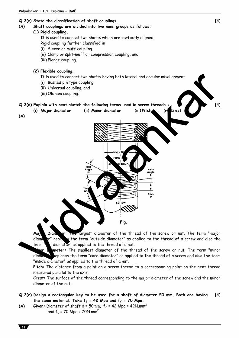
Q.3(d) Explain with neat sketch the following terms used in screw threads :
(i) Major diameter (ii) Minor diameter (iii) Pitch (iv) Crest [4]
(A)
Fig.
Major Diameter: The largest diameter of the thread of the screw or nut. The term "major diameter" replaces the term "outside diameter" as applied to the thread of a screw and also the term "full diameter" as applied to the thread of a nut. Minor Diameter: The smallest diameter of the thread of the screw or nut. The term "minor diameter" replaces the term "core diameter" as applied to the thread of a screw and also the term "inside diameter" as applied to the thread of a nut. Pitch: The distance from a point on a screw thread to a corresponding point on the next thread measured parallel to the axis. Crest: The surface of the thread corresponding to the major diameter of the screw and the minor diameter of the nut.
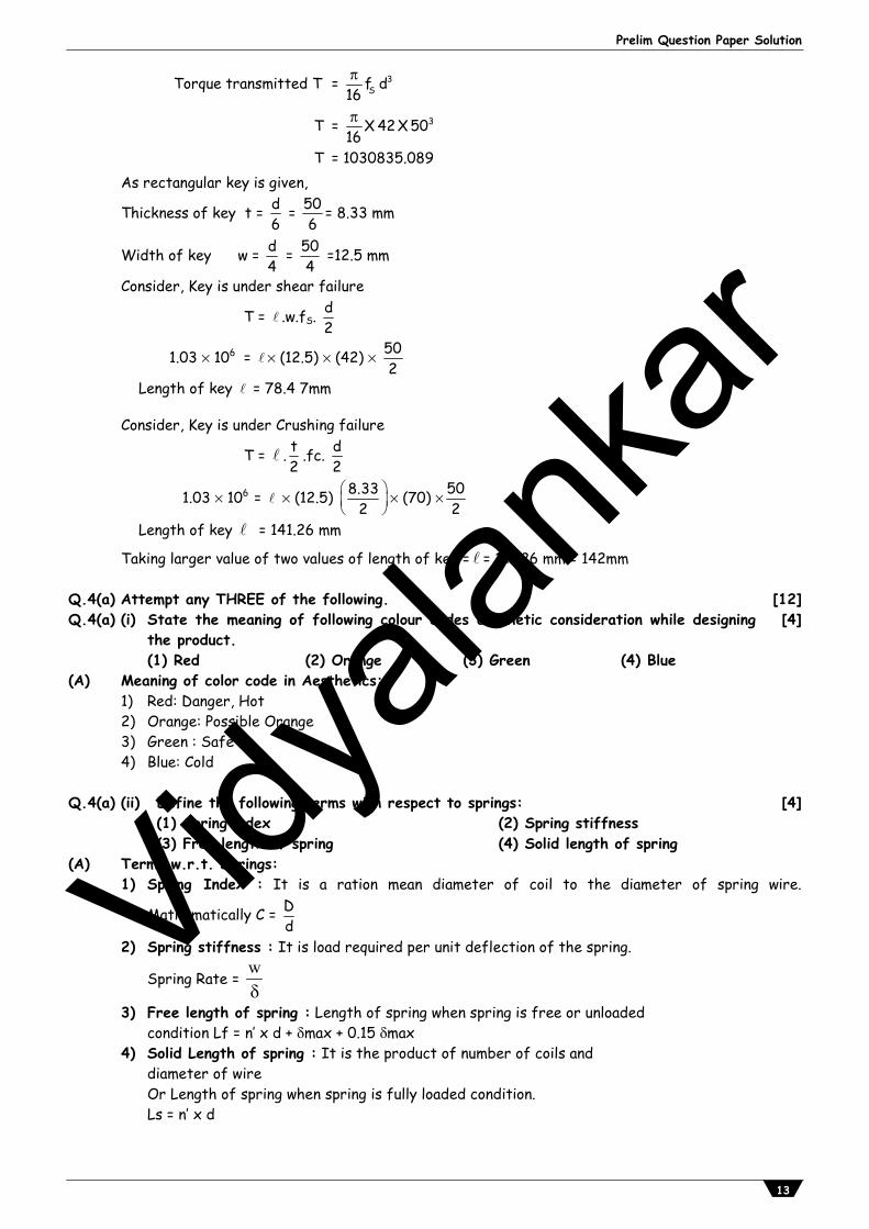
Q.3(e) Design a rectangular key to be used for a shaft of diameter 50 mm. Both are having
the same material. Take fS = 42 Mpa and fC = 70 Mpa. [4]
(A) Given: Diameter of shaft d = 50mm, fS = 42 Mpa = 42N.mm2 and fC = 70 Mpa = 70N.mm2
Vidyala
nkar
Prelim Question Paper Solution
13
Torque transmitted T = 3Sf d
16
T = 3X 42X 5016
T = 1030835.089
As rectangular key is given,
Thickness of key t = d6
= 506
= 8.33 mm
Width of key w = d4
= 504
=12.5 mm
Consider, Key is under shear failure
T = .w.fS. d2
1.03 106 = (12.5) (42) 502
Length of key = 78.4 7mm Consider, Key is under Crushing failure
T = . t2
.fc. d2
1.03 106 = (12.5) 8.332
(70) 502
Length of key = 141.26 mm
Taking larger value of two values of length of key = = 141.26 mm = 142mm Q.4(a) Attempt any THREE of the following. [12]Q.4(a) (i) State the meaning of following colour codes aesthetic consideration while designing
the product. (1) Red (2) Orange (3) Green (4) Blue
[4]
(A) Meaning of color code in Aesthetics: 1) Red: Danger, Hot 2) Orange: Possible Orange 3) Green : Safe 4) Blue: Cold Q.4(a) (ii) Define the following terms with respect to springs:
(1) Spring index (2) Spring stiffness (3) Free length of spring (4) Solid length of spring
[4]
(A) Terms w.r.t. Springs: 1) Spring Index : It is a ration mean diameter of coil to the diameter of spring wire.
Mathematically C = Dd
2) Spring stiffness : It is load required per unit deflection of the spring.
Spring Rate = w
3) Free length of spring : Length of spring when spring is free or unloaded condition Lf = n’ x d + max + 0.15 max 4) Solid Length of spring : It is the product of number of coils and diameter of wire Or Length of spring when spring is fully loaded condition. Ls = n’ x d
Vidyala
nkar
Vidyalankar : T.Y. Diploma DME
14
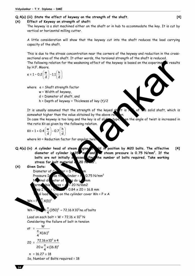
Q.4(a) (iii) State the effect of keyway on the strength of the shaft. [4](A) Effect of Keyway on strength of shaft:
The keyway is a slot machined either on the shaft or in hub to accommodate the key. It is cut by vertical or horizontal milling cutter. A little consideration will show that the keyway cut into the shaft reduces the load carrying capacity of the shaft. This is due to the stress concentration near the corners of the keyway and reduction in the cross-sectional area of the shaft. It other words, the torsional strength of the shaft is reduced. The following relation for the weakening effect of the keyway is based on the experimental results by H.F. Moore.
e = 1 – 0.2 w h1.1d d
where e = Shaft strength factor w = Width of keyway, d = Diameter of shaft, and h = Depth of keyway = Thickness of key (t)/2 It is usually assumed that the strength of the keyed shaft is 75% of the solid shaft, which is somewhat higher than the value obtained by the above relation. In case the keyway is too long and the key is of sliding type, then the angle of twist is increased in the ratio K as given by the following relation.
K = 1 + 0.4 w h0.7d d
where k = Reduction factor for angular twist. Q.4(a) (iv) A cylinder head of steam engine is held in position by M20 bolts. The effective
diameter of cylinder is 350 mm and the steam pressure is 0.75 N/mm2. If the bolts are not initially stressed, find the number of bolts required. Take working stress for bolt material as 20 N/mm2.
[4]
(A) Given Data: Diameter of Cylinder = D = 350mm Pressure Inside the cylinder = P = 0.75 N/mm2
Nominal diameter of bolts do = 20mm Permissible stress = σt = 20 N/mm2 Step I : dc = 0.84 do = 0.84 x 20 = 16.8 mm Total load acting on the cylinder cover Wn = P x A
Wn = PX 2X(D)4
Wn = 0.75 X 2 3(350) 72.16X10 no. ofbolts4
Load on each bolt = W = 72.16 x 10³ N Considering the failure of bolt in tension
σt = 2
W
X(dc)4
20 = 3
2
72.16 x10 x 4
20 x x (16.8)4
n = 16.27 18 So, Number of Bolts required = 18
Vidyala
nkar
Prelim Question Paper Solution
15
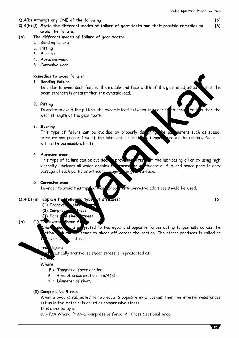
Q.4(b) Attempt any ONE of the following [6]Q.4(b) (i) State the different modes of failure of gear teeth and their possible remedies to
avoid the failure. [6]
(A) The different modes of failure of gear teeth: 1. Bending failure. 2. Pitting 3. Scoring. 4. Abrasive wear. 5. Corrosive wear
Remedies to avoid failure: 1. Bending failure
In order to avoid such failure, the module and face width of the gear is adjusted so that the beam strength is greater than the dynamic load.
2. Pitting In order to avoid the pitting, the dynamic load between the gear tooth should be less than the
wear strength of the gear tooth. 3. Scoring This type of failure can be avoided by properly designing the parameters such as speed,
pressure and proper flow of the lubricant, so that the temperature at the rubbing faces is within the permissible limits.
4. Abrasive wear
This type of failure can be avoided by providing filters for the lubricating oil or by using high viscosity lubricant oil which enables the formation of thicker oil film and hence permits easy passage of such particles without damaging the gear surface.
5. Corrosive wear In order to avoid this type of wear, proper anti-corrosive additives should be used.
Q.4(b) (ii) Explain the following types of stresses:
(1) Transverse shear stress (2) Compressive stress (3) Torsional shear stress
[6]
(A) (1) Transverse Shear Stress When a section is subjected to two equal and opposite forces acting tangentially across the
section such that it tends to shear off across the section. The stress produces is called as transverse shear stress.
From figure Mathematically transverse shear stress is represented as, = F/A Where, F = Tangential force applied A = Area of cross section = (π/4) d2
d = Diameter of rivet. (2) Compressive Stress When a body is subjected to two equal & opposite axial pushes, then the internal resistances
set up in the material is called as compressive stress. It is denoted by σc σc = P/A Where, P: Axial compressive force, A : Cross Sectional Area.
Vidyala
nkar
Vidyalankar : T.Y. Diploma DME
16
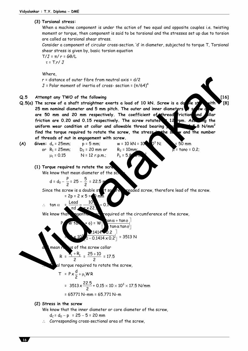
(3) Torsional stress: When a machine component is under the action of two equal and opposite couples i.e. twisting
moment or torque, then component is said to be torsional and the stresses set up due to torsion are called as torsional shear stress.
Consider a component of circular cross-section. ‘d’ in diameter, subjected to torque T, Torsional shear stress is given by, basic torsion equation
T/J = π/r = Gθ/L = T.r/ J Where, r = distance of outer fibre from neutral axis = d/2 J = Polar moment of inertia of cross- section = (π/64)4
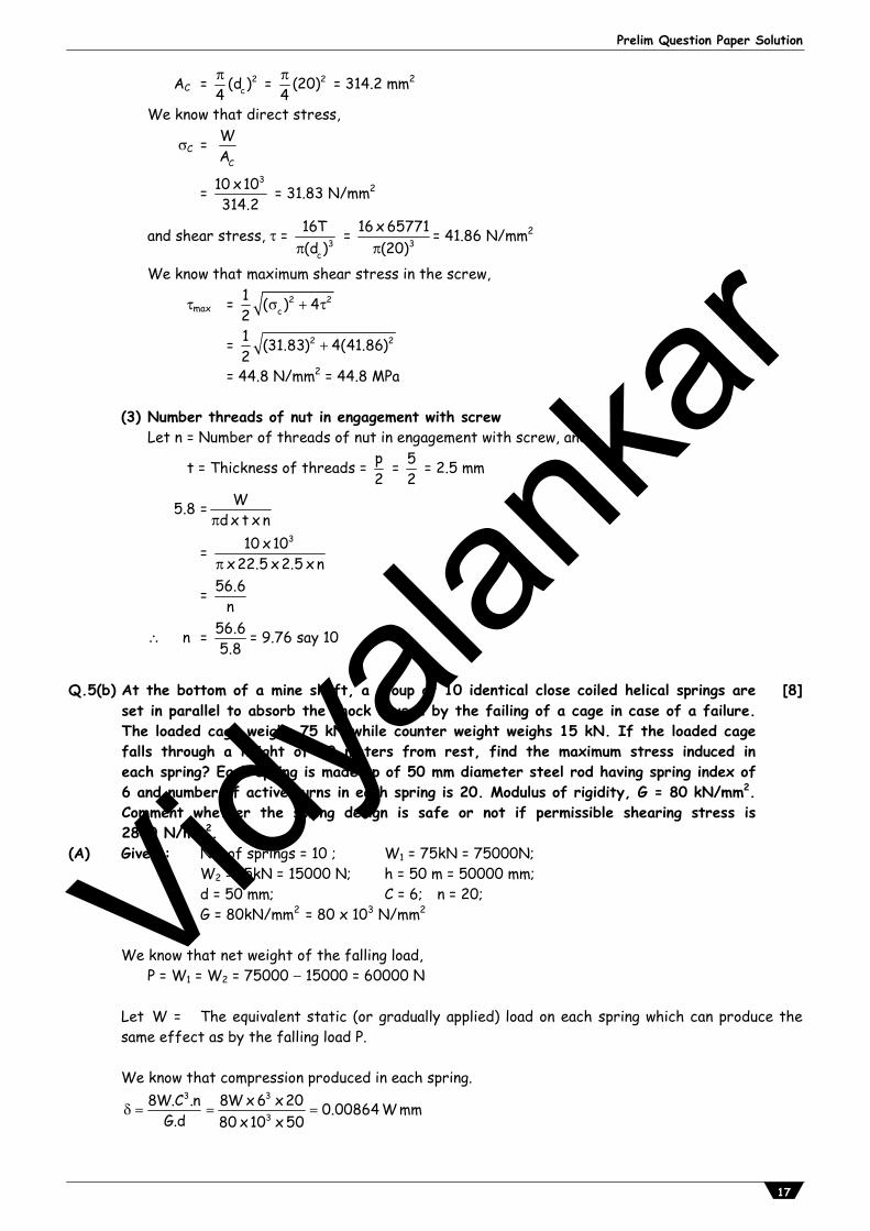
Q.5 Attempt any TWO of the following [16]Q.5(a) The screw of a shaft straightner exerts a load of 10 kN. Screw is a double start with
25 mm nominal diameter and 5 mm pitch. The outer and inner diameters of screw collar are 50 mm and 20 mm respectively. The coefficient of thread friction and collar friction are 0.20 and 0.15 respectively. The screw rotates at 12 rpm. Assuming the uniform wear condition at collar and allowable thread bearing pressure of 5.8 N/mm2
find the torque required to rotate the screw, the stress in the screw and the number of threads of nut in engagement with screw.
[8]
(A) Given: do = 25mm; p = 5 mm; w = 10 kN = 10 x 103 N; D1 = 50 mm or R1 = 25mm; D2 = 20 mm or R2 = 10mm; = tan = 0.2; 1 = 0.15 N = 12 r.p.m.; Pb = 5.8 N/mm2
(1) Torque required to rotate the screw We know that mean diameter of the screw,
d = d0 P2
= 25 52
= 22.5 mm
Since the screw is a double start square threaded screw, therefore lead of the screw. = 2p = 2 x 5 = 10 mm
tan = Lead 10 0.1414d x22.5
We know that tangential force required at the circumference of the screw,
P = W tan( + ) = W tan tan1 tan tan
= 10 x 1030.1414 0.2
1 0.1414 x 0.2 = 3513 N
and mean radius of the screw collar
R = 1 2R R2
= 25 102 = 17.5
Total torque required to rotate the screw,
T = 1dP x W R2
= 22.53513x2
+ 0.15 10 103 17.5 N/mm
= 65771 Nmm = 65.771 Nm
(2) Stress in the screw We know that the inner diameter or core diameter of the screw, dC = d0 p = 25 5 = 20 mm Corresponding cross-sectional area of the screw,
Vidyala
nkar
Prelim Question Paper Solution
17
AC = 2c(d )
4 = 2(20)
4 = 314.2 mm2
We know that direct stress,
C = C
WA
= 310 x10
314.2 = 31.83 N/mm2
and shear stress, = 3c
16T(d )
= 316 x 65771
(20)
= 41.86 N/mm2
We know that maximum shear stress in the screw,
max = 2 2c
1 ( ) 42
= 2 21 (31.83) 4(41.86)2
= 44.8 N/mm2 = 44.8 MPa (3) Number threads of nut in engagement with screw Let n = Number of threads of nut in engagement with screw, and
t = Thickness of threads = p2
= 52
= 2.5 mm
5.8 = Wd x t x n
= 310 x10
x22.5 x2.5 x n
= 56.6n
n = 56.65.8
= 9.76 say 10
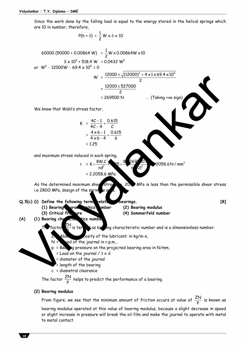
Q.5(b) At the bottom of a mine shaft, a group of 10 identical close coiled helical springs are
set in parallel to absorb the shock caused by the failing of a cage in case of a failure.The loaded cage weighs 75 kN while counter weight weighs 15 kN. If the loaded cagefalls through a height of 50 meters from rest, find the maximum stress induced ineach spring? Each spring is made up of 50 mm diameter steel rod having spring index of6 and number of active turns in each spring is 20. Modulus of rigidity, G = 80 kN/mm2.Comment whether the spring design is safe or not if permissible shearing stress is2800 N/mm2.
[8]
(A) Given : No. of springs = 10 ; W1 = 75kN = 75000N; W2 = 15kN = 15000 N; h = 50 m = 50000 mm; d = 50 mm; C = 6; n = 20; G = 80kN/mm2 = 80 x 103 N/mm2 We know that net weight of the falling load, P = W1 = W2 = 75000 15000 = 60000 N Let W = The equivalent static (or gradually applied) load on each spring which can produce the
same effect as by the falling load P. We know that compression produced in each spring.
3 3
38W.C .n 8W x 6 x20 0.00864 W mm
G.d 80 x10 x 50
Vidyala
nkar
Vidyalankar : T.Y. Diploma DME
18
Since the work done by the falling load is equal to the energy stored in the helical springs which are 10 in number, therefore,
P(h + ) = 12
W x x 10
60000 (50000 + 0.00864 W) = 1 W x 0.00864W x102
3 x 10⁹ + 518.4 W = 0.0432 W2
or W2 12000W 69.4 x 109 = 0
W = 2 912000 (12000) 4 x1 x 69.4 x102
= 12000 5270002
= 269500 N (Taking +ve sign) We know that Wahl’s stress factor,
K = 4C 1 0.6154C 4 C
= 4 x 6 1 0.6154 x 6 4 6
= 1.25
and maximum stress induced in each spring,
= 28W.CK
d´ = 2
28 x269500 x 61.25 2058.6N / mm
(50)
´ =
= 2.2058.6 MPa As the determined maximum shear stress i.e .2058 MPa is less than the permissible shear stress i.e 280O MPa, design of the spring is safe.
Q.5(c) (i) Define the following terms related to bearings.
(1) Bearing characteristics number (2) Bearing modulus (3) Critical Pressure (4) Sommerfeld number
[8]
(A) (1) Bearing characteristics number
The factor ZNP
is termed as bearing characteristic number and is a dimensionless number.
Z = Absolute viscosity of the lubricant; in kg/m-s, N = Speed of the journal in r.p.m., p = Bearing pressure on the projected bearing area in N/mm, = Load on the journal / 1 x d d = diameter of the journal l = length of the bearing c = diametral clearance
The factor ZNP
helps to predict the performance of a bearing.
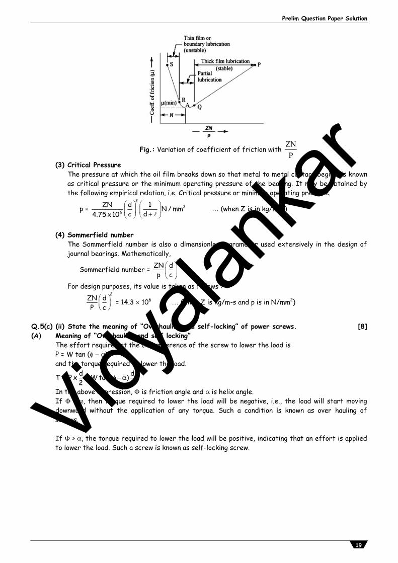
(2) Bearing modulus
From figure, we see that the minimum amount of friction occurs at value of ZNP
is known as
bearing modulus operated at this value of bearing modulus, because a slight decrease in speed or slight increase in pressure will break the oil film and make the journal to operate with metal to metal contact.
Vidyala
nkar
Prelim Question Paper Solution
19
Fig.: Variation of coefficient of friction with ZNP
(3) Critical Pressure The pressure at which the oil film breaks down so that metal to metal contact begins, is known
as critical pressure or the minimum operating pressure of the bearing. It may be obtained by the following empirical relation, i.e. Critical pressure or minimum operating pressure.
p = 2
26
ZN d 1 N / mmc d4.75 x10
(when Z is in kg/ms)
(4) Sommerfield number The Sommerfield number is also a dimensionless parameter used extensively in the design of
journal bearings. Mathematically,
Sommerfield number = 2
ZN dp c
For design purposes, its value is taken as follows :
2
ZN dP c
= 14.3 106 (when Z is kg/m-s and p is in N/mm2)
Q.5(c) (ii) State the meaning of “Overhauling and self-locking” of power screws. [8](A) Meaning of “Overhauling and self locking” The effort required at the circumference of the screw to lower the load is P = W tan ( ) and the torque required to lower the load.
T = d dP x W tan ( )2 2
In the above expression, is friction angle and is helix angle. If < , then torque required to lower the load will be negative, i.e., the load will start moving
downward without the application of any torque. Such a condition is known as over hauling of screws.
If > , the torque required to lower the load will be positive, indicating that an effort is applied
to lower the load. Such a screw is known as self-locking screw.
Vidyala
nkar
Vidyalankar : T.Y. Diploma DME
20
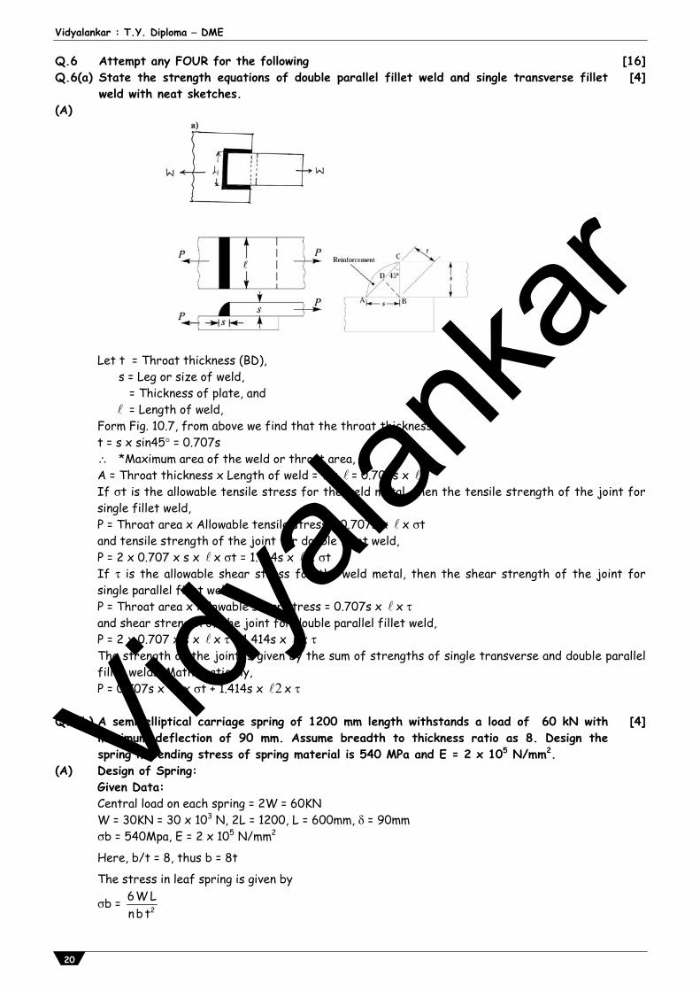
Q.6 Attempt any FOUR for the following [16]Q.6(a) State the strength equations of double parallel fillet weld and single transverse fillet
weld with neat sketches. [4]
(A)
Let t = Throat thickness (BD), s = Leg or size of weld, = Thickness of plate, and = Length of weld, Form Fig. 10.7, from above we find that the throat thickness, t = s x sin45 = 0.707s *Maximum area of the weld or throat area, A = Throat thickness x Length of weld = t x = 0.707s x If t is the allowable tensile stress for the weld metal, then the tensile strength of the joint for single fillet weld, P = Throat area x Allowable tensile stress = 0.707s x x t and tensile strength of the joint for double fillet weld, P = 2 x 0.707 x s x x t = 1.414s x x t If is the allowable shear stress for the weld metal, then the shear strength of the joint for single parallel fillet weld, P = Throat area x Allowable shear stress = 0.707s x x and shear strength of the joint for double parallel fillet weld, P = 2 x 0.707 x s x x = 1.414s x x The strength of the joint is given by the sum of strengths of single transverse and double parallel fillet welds. Mathematically, P = 0.707s x 1 x t + 1.414s x 2 x
Q.6(b) A semi-elliptical carriage spring of 1200 mm length withstands a load of 60 kN with
maximum deflection of 90 mm. Assume breadth to thickness ratio as 8. Design thespring if bending stress of spring material is 540 MPa and E = 2 x 10⁵ N/mm2.
[4]
(A) Design of Spring: Given Data: Central load on each spring = 2W = 60KN W = 30KN = 30 x 103 N, 2L = 1200, L = 600mm, = 90mm b = 540Mpa, E = 2 x 10⁵ N/mm2
Here, b/t = 8, thus b = 8t
The stress in leaf spring is given by
b = 26W Lnbt
Vidyala
nkar
Prelim Question Paper Solution
21
n x b x t2 = 3
36W L 6 x30 x10 x 600 200 x10b 540
(I)
3
36W LnE b t
n x b x t3 = 3(6W L )
x E
n x b x t3 = 3 3
56 x30 x10 x 600
90 x2 x10
= 2.16 x 10³ (II)
Dividing equation II by equation I, we get t = 10.8mm b = 8t = 8 x 10.8 = 86.4mm from equation I, n x b x t2 = 200 x 103 n x 86.4 x 10.82 = 200 x 103 n = 19.84 20 Total Number of leaves n = 20 Numbers
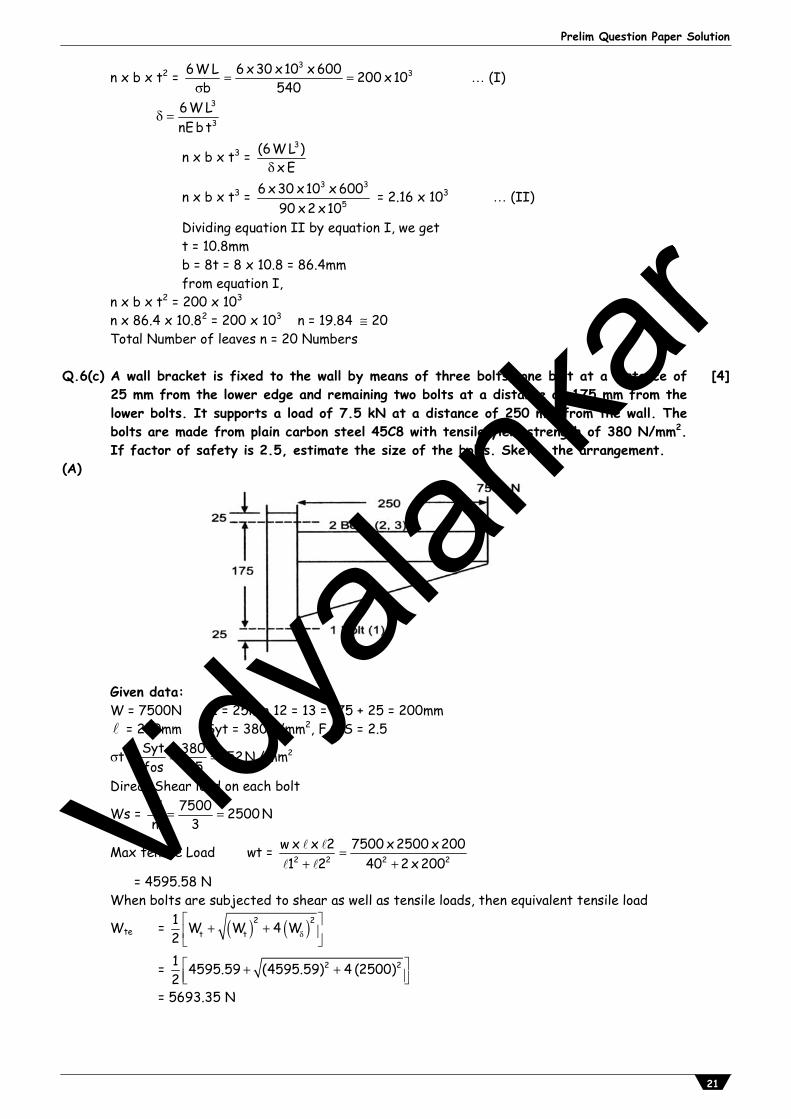
Q.6(c) A wall bracket is fixed to the wall by means of three bolts, one bolt at a distance of
25 mm from the lower edge and remaining two bolts at a distance of 175 mm from thelower bolts. It supports a load of 7.5 kN at a distance of 250 mm from the wall. Thebolts are made from plain carbon steel 45C8 with tensile yield strength of 380 N/mm2.If factor of safety is 2.5, estimate the size of the bolts. Sketch the arrangement.
[4]
(A)
Given data: W = 7500N 11 = 25mm 12 = 13 = 175 + 25 = 200mm = 250mm Syt = 380N/mm2, F.O.S = 2.5
t = 2Syt 380 152N / mmfos 2.5
Direct Shear load on each bolt
Ws = W 7500 2500 Nn 3
Max tensile Load wt = 2 2 2 2w x x 2 7500 x 2500 x 2001 2 40 2 x 200
= 4595.58 N When bolts are subjected to shear as well as tensile loads, then equivalent tensile load
Wte = 2 2t t
1 W W 4 W2
= 2 21 4595.59 (4595.59) 4 (2500)2
= 5693.35 N
Vidyala
nkar
Vidyalankar : T.Y. Diploma DME
22
Knowing the value of load, Size of bolt
t = 2
Wte
x dc4
152 = 2
5693.35
x dc4
dc = 6.90mm, do = 6.90/0.84 = 8.22 10mm Bolt size may be M10
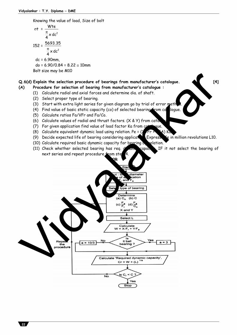
Q.6(d) Explain the selection procedure of bearings from manufacturer’s catalogue. [4](A) Procedure for selection of bearing from manufacturer’s catalogue : (1) Calculate radial and axial forces and determine dia. of shaft. (2) Select proper type of bearing. (3) Start with extra light series for given diagram go by trial of error method. (4) Find value of basic static capacity (co) of selected bearing from catalogue. (5) Calculate ratios Fa/VFr and Fa/Co. (6) Calculate values of radial and thrust factors. (X & Y) from catalogue. (7) For given application find value of load factor Ka from catalogue. (8) Calculate equivalent dynamic load using relation. Pe = (XVFr + YFA) Ka. (9) Decide expected life of bearing considering application. Express life in million revolutions L10. (10) Calculate required basic dynamic capacity for bearing by relation. (11) Check whether selected bearing has req. dynamic capacity, IF it not select the bearing of
next series and repeat procedure from step-4. OR
Vidyala
nkar
Prelim Question Paper Solution
23
Q.6(e) Sate the applications of following bearings with suitable reasons: (i) Deep grove ball bearing (ii) Taper roller bearing (iii) Thrust coller bearingdds (iv) Needle roller bearing
[4]
(A) Application of bearings: (i) Deep Groove Ball bearing : Application: Electric Motor. Reason: Capacity to take heavily axial load with high rotational speed. (ii) Taper roller bearing Application: axle housing of automobile. Reason: ability to take high radial load as well as thrust load. (iii) Thrust collar bearing : Application: Clutch of automobile. Reason: ability to combine radial & axial load with min. speed. (iv) Needle roller bearing : Application: Differential of automobile Reason: takes less radial space. it has high radial load carrying capacity.
Vidyala
nkar


![Design of Steel Structures - diploma.vidyalankar.org · Design of Steel Structures Time: 4 Hrs.] Prelim Question Paper Solution [Marks : 100 Q.1(a) Attempt any THREE of the following](https://img.pdfslide.net/doc/110x75/604c8a1c9691966b413c9c20/design-of-steel-structures-design-of-steel-structures-time-4-hrs-prelim-question.jpg)
![S.Y. Diploma : Sem. IV [EJ/EX/ET/EN/IS/IC/IE/IU] Analog ...diploma.vidyalankar.org/prelim-papers/SY/ETRX/AC_Soln.pdf · amplitude. This unwanted amplitude change should be removed](https://img.pdfslide.net/doc/110x75/5f7707b5292e0a34126be754/sy-diploma-sem-iv-ejexetenisicieiu-analog-amplitude-this-unwanted.jpg)


![Time : 3 Hrs.] Prelim Question Paper Solution [Marks : 100 ...diploma.vidyalankar.org/wp-content/uploads/RES_Soln.pdf · Prelim Question Paper Solution [Marks : 100 ... These are](https://img.pdfslide.net/doc/110x75/5ad901ba7f8b9a991b8e075c/time-3-hrs-prelim-question-paper-solution-marks-100-question-paper-solution.jpg)