Embed Size (px)
Citation preview
Science in China Series E: Technological Sciences
© 2009 SCIENCE IN CHINA PRESS
Citation: Li J Z. Time amplifying techniques towards atomic time resolution. Sci China Ser E-Tech Sci, 2009, 52(12): 3425―3446, doi: 10.1007/s11431-009-0381-0
www.scichina.com tech.scichina.com
www.springerlink.com
Time amplifying techniques towards atomic time resolution
LI JingZhen
Institute of Photonic Engineering, College of Electron Science & Technology, Shenzhen University, and Shenzhen Key Laboratory of Micro·Nano Photonic Information, Shenzhen 518060, China
High speed imaging technology has opened applications in many fields, such as collision, detonating, high voltage discharge, disintegration and transfer of phonon and exciton in solid, photosynthesis primitive reaction, and electron dynamics inside atom shell. In principle, all of the transient processes need to be explained theoretically and, at the same time, the time amplifying technique is required for observations of these processes. The present review concerns the atomic time amplifying mechanism of optical information and the extremely-high speed imaging methods, which are expressed in terms of the short time amplifying techniques. It is well-known that for extremely-high speed imaging with the converter tube, the temporal resolution is in the order of sub-picosecond of the streak imaging, and the imaging frequency is 6×10⁸―5×10⁹ fps (frame per second) of the frame imaging. On the other hand, for the tubeless extremely-high speed imaging, the imaging frequency is 107―1014 fps, and its mechanism of forming high speed and framing could involve a lot of factors of the light under investigation, for instance, light speed, light parallelism, the parameters of light wave such as amplitude, phase, polari-zation and wavelength, and even quantum properties of photon. In the cascaded system of electro-magnetic wave and particle wave, it is possible to simultaneously realize extremely-high resolution in time and space, which is higher than a kite resolution. Then it would be possible to break the limit of the Heisenberg uncertainty relation of the optical frequency band.
time amplification, image converter tube imaging, tubeless imaging, ultra-high speed imaging, extremely-high speed imaging, holog- raphic coherent shutter, optical acceleration
In the opening conference of the Committee on High Speed Photography and Photonics of the Chinese Opti-cal Society, held in 1981, Prof. Wang Daheng suggested that the topics concerning high speed photography should belong to the fields of speediness physics. After that, Prof. Gong Zutong, Prof. Hou Xun, and some other outstanding scientists created a term “transient optics” according to its optical attribute. With the identical con-cept, “speediness physics” and “high speed photogra-phy” were introduced then. They are stated from the various viewpoints of the different subjects and aim at investigations of the theory and technique of the time amplification. Basically, the transient optics is presented for resolving the scientific problems about observations
and probes of the optical information in the short time processes, in particular, in the atomic time processes. The regions on the short time and the atomic time are listed in Table 1[1], in comparison with the long time.
A microscopic technique is defined as the spatial am- plification of the microscopic field, which enhances the spatial resolving ability of human eyes. In contrast, the high speed imaging is defined as the temporal amplifica- tion of the transient events, including macrocosmic, finecosmic and microcosmic ones, which enhances Received June 24, 2009; accepted August 25, 2009 doi: 10.1007/s11431-009-0381-0 email: [email protected] Supported by the National Natural Science Foundation of China (Grant Nos. 60477042 and 60127501)
3426 Li J Z. Sci China Ser E-Tech Sci | Dec. 2009 | vol. 52 | no. 12 | 3425-3446
Table 1 Time
the temporal resolving ability of human eyes. The ulti-mate strobe time resolution of a human eyes, dependent on the brightness, the background and the color of tran-sient events, is usually between 1/50 s and 1/5 s. By tak-ing eliminating the stroboscopic effect and the vision per-sistence of human eyes into account, the standard fre-quency of photography is set to be 24 fps[2―4]. Usually, the time amplifying is expressed as the ratio of imaging frequency to 24 fps for the frame imaging or the ratio to 0.042 s, which is the average of time resolving limit, over temporal resolution for the streak imaging.
In the high speed imaging field, the time amplifying technique may be divided generally into the short time amplifying technique and the atomic time amplifying one, which covers 10−3―10−12 s and 10−12―10−18 s, re-spectively. Imaging techniques with the different princi-ples, kinds and temporal resolutions are needed for re-search on transient events with the different properties, kinds and character times. In the short time amplifying technique for optical information there exist millisecond and sub-millisecond imaging technique for some kinds of launching and colliding, the microsecond and sub-microsecond imaging technique for some kinds of exploding, detonating, and shockwave, and the nano-second and sub-nanosecond imaging technique for high voltage discharge and flying flake by laser. In the atomic time amplifying technique for optical information, the different time scale imaging techniques are proposed for the different applications: picosecond imaging technique for disintegration and transfer of phonon and exciton in solid, unbinding phase time and molecule vibration re-laxation in liquid, and plasma increasing and attenuation in both solid and gas; the femtosecond imaging tech-nique for molecule structure dynamics such as atom vi-bration, fragmentation and formation of chemical bond, photosynthesis primitive reaction, vision process and super velocity surface dynamic processes; and the atto-second imaging technique for movement of high energy ion and heat energy electron, valence electron movement, and electronic dynamics in atomic shell, named bound electron dynamics including excitation, ionization and recombination[5―10].
According to the optical theory of degree of free-dom[11], the information capacity of a dynamic light field can be written in this form: s t c p 2log (1 ),C N N N N h g mα β= ⋅ ⋅ ⋅ ⋅ ⋅ + (1)
where Ns is the spatial freedom as a product of frame size and spatial resolution, or the space-bandwidth product; h the spatial information factor, particularly, hα
with α =1/4 corresponding to the ultra-high speed im-aging with a rotating mirror; Nt=fT the temporal free-dom as a time-bandwidth product of transient events, f being the imaging frequency (the reciprocal of time resolution Δt) and T being the recording time; g the ratio of a framing time to an exposure time, particularly, gβ as the time-information factor with β=2/3 for the ultra-high speed imaging with a rotating mirror; Nc the freedom of color, equal to the number of wavelength channels; Np the freedom of polarization, associated with the number of polarization channels; m the ratio of signal to noise.
The key target of high speed imaging lies in im-provement of the information capacity of a dynamic light field. Eq. (1) gives the way to improve the infor-mation capacity of the dynamic light field, at the same time it serves as an objective function for estimation of the imaging technique level and provides the encoding method of multi-frame record. Increase of values of the parameters, including the picture frame size, spatial resolution, imaging frequency and recording time, is a valid way to improve the information capacity of the dynamic light field. This is the common trend for all kinds of imaging technique, where increase of spatial resolution and temporal resolution is a long-term goal pursued by human. However, the different imaging techniques are applied for the different kinds of transient events, particularly emphasizing different performances. Actually, the information capacity of the dynamic light field is limited by imaging principle and imaging tech-nique. The information capacity of the dynamic light field can be increased by means of reasonable selection of the time-information factor and the space- informa-tion factor, which must be considered in designing high speed imaging devices. The polarization freedom and the color freedom are usually concerned in extremely-
Li J Z. Sci China Ser E-Tech Sci | Dec. 2009 | vol. 52 | no. 12 | 3425-3446 3427
high speed imaging, especially in femtosecond imaging region, in order to realize forming and framing of time sequence parallel multi-channel extremely-high speed imaging. In fact, it is exact enough to consider the spa-tial freedom and the time freedom of one dimension case for understanding the level and limit of a variety of im-aging techniques. From eq. (1), a simple expression of the information capacity of the dynamic light field in record can be derived in the form: ,I Bnf= (2) where B is the frame size (mm) of the time orientation, n the corresponding spatial resolution (lp/mm), and f the imaging frequency (fps).
We now discuss the differences between the imaging techniques with and without the image converter tube[12,13], which are named the converter tube imaging and the tubeless imaging. The former is composed of an optical system and an imaging system with wide elec-tron beam. It works with three conversion processes: from optical image to electron image, then to optical image, and finally to chemical image (or charge image). In contrast, the tubeless imaging consists of only an op-tical system, just having one conversion process from optical image to chemical image (or charge image). Further development of tubeless imaging in frequency range from 102 fps to 1014 fps will depend on the recent achievements in some research fields, such as high speed film transport technique, ultra-high-speed rotating mirror technique, optical acceleration technique, opto-
electrical imaging technique with solid-state picture de-vice, opto-mechanical technique, opto-electrical tech-nique, electro-optical shutter array technique, and opto-
optical technique.
1 Millisecond and sub-millisecond imag- ing techniques
The high speed imaging is based on two different prin-ciples: the exposal principle and framing principle. In the exposal principle, the transient event is relatively static during the exposure time of the recording medium used in the optical image. In contrast, the framing prin-ciple corresponds to relatively moving case. In such two cases, the imaging processes are controlled by the shut-ter and high-speed forming system, respectively. Mean-while, further studies have shown that the maximum time-space information amount can be obtained by the separation between the exposal function and the framing
function. In the high speed film transport imaging, as the main part of the millisecond and sub-millisecond imag-ing technique, the two principles are utilized by the mo-tion of film and the placket lappet shutter (or roller shutter). The speed of film transport is limited by the type of the film and the action property of the film transport force on the film, which can be described by the differential equation for film transport dynamics. The high speed film transport includes intermittent film transport and continuous film transport, which corre-spond to the intermittent high speed imaging and optical compensation high speed imaging, respectively.
1.1 Intermittent high speed imaging
The intermittent high speed imaging is in coincidence with the basic principles of high speed imaging, without principle error. The pin fixes the film during the expo-sure time, and then the pull-down claw takes the film to shift a picture-frame’s distance. It therefore can provide high quality image, and the dynamic spatial resolution of imaging can reach 50―70 lp/mm, and the uncertainty of the frame stability is less than ±0.02 mm[14]. The imag-ing frequency of intermittent high speed imaging is lim-ited by the strength of film, the strength of the intermit-tent mechanism and driving technique. Recently, it ap-proaches the limiting level of such imaging technique. Although the intermittent high speed imaging has been developed for a long period and its technology has be-come mature, it still remains under development. It is of some advantages such as the fine imaging quality, better reliability and stability in harsh conditions, especially, theory and experiment of the intermittent mechanism, the new intermittent mechanism and the intermittent high speed imaging technique with large size picture. The main achievements concerning the intermittent high speed imaging made in China are described as follows:
(1) The breakthroughs have been made in intermittent frame transport micro-dynamics principle. In fact, the film transport force has been confirmed in terms of theories and experiments to be discontinuous, and it is composed of the pulse bursts. It is contrary to the com-monly accepted viewpoint. The film down-rushing rule and the equistroke film transporting have also been found. These progresses provide a basis for design of intermittent mechanism[15,16].
(2) Two important kinds of camera have been pro-duced successfully: the airborne intermittent high speed mini-camera, i.e. WJJ-16mm[17], and the airborne inter-
3428 Li J Z. Sci China Ser E-Tech Sci | Dec. 2009 | vol. 52 | no. 12 | 3425-3446
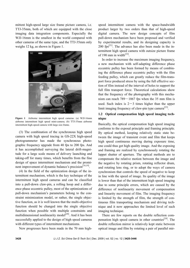
mittent high-speed large size frame picture camera, i.e. TTJ-35mm, both of which are equipped with the close imaging data integration components. Especially the WJJ-16mm is the smallest in the world compared with other cameras of the same type, and the TTJ-35mm only weighs 12 kg, as shown in Figure 1.
Figure 1 Airborne intermittent high speed cameras. (a) WJJ-16mm airborne intermittent high speed mini-camera; (b) TTJ-35mm airborne intermittent high-speed camera with large size frame.
(3) The combination of the synchronous high speed
camera with high speed tracing in GS-22X high-speed photogrammeter has made the synchronous photo-graphic frequency upgrade from 40 fps to 200 fps. And it has accomplished surveying the lateral drift- magni- tude for a large scale means of delivery launching and taking-off for many times, which benefits from the fine design of space intermittent mechanism and the promi- nent improvement of dynamic balance’s precision[18,19].
(4) In the field of the optimization design of the in-termittent mechanism, which is the key technique of the intermittent high speed cameras and can be classified into a pull-down claw-pin, a rolling hoop and a differ-ence phase eccentric pulley, most of the optimizations of pull-down mechanism’s parameters belong to the con-straint minimization model, or rather, the single objec-tive function, as it is well known that the multi-objective function should be changed into the single objective function when possible with multiple constraints and multidimensional nonlinearity model[20]. And it has been successfully applied to the design of high speed cameras with different types of intermittent mechanisms.
New progresses have been made in the 70 mm high-
speed intermittent camera with the space-bandwidth product larger by two orders than that of high-speed digital camera. The new design concepts of film pull-down mechanism have been proposed and verified by experimental results, and its designing capacity is 200 fps[21]. The advance has also been made in the in-termittent high speed camera with outsize picture frame of 190 mm in width[22].
In order to increase the maximum imaging frequency, a new mechanism with self-adapting difference phase eccentric pulley has been formed by means of combin-ing the difference phase eccentric pulley with the film feeding pulley, which can greatly reduce the film- trans-port force produced stress by using the full effective sec-tion of film instead of the interval of holes to support the full film transport force. Theoretical calculations show that the frequency of the photography with this mecha-nism can reach 789―1067 fps when the 35 mm film is used. Such index is 2―3 times higher than the upper limit imaging frequency of claw-pin type camera[23].
1.2 Optical compensation high speed imaging tech-nique
Basically, the optical compensation high speed imaging conforms to the exposal principle and framing principle. By optical method, keeping relatively static state be-tween the image of transient event and film that keeps high speed continuous moving during exposure time, one could thus get high quality image. And the exposing and framing are realized by synchronously rotating the lappet shutter of aperture. The optical methods are to compensate the relative motion between the image and the negative by rotating prism, rotating reflector drum, and rotating lens ring, or to adopt the ways of camera synchronism that controls the speed of negative to keep in line with the speed of image. Its quality of the image is lower than that of the intermittent high speed imaging due to some principle errors, which are caused by the difference of nonlinearity movement of compensation and linearity movement of film. The imaging frequency is limited by the strength of film, the strength of con-tinuous film transporting mechanism and driving tech-nique and it now approaches the limited level of such imaging technique.
There are few reports on the double reflection com-pensation high speed camera in other countries[24]. The double reflection mirror is relatively kept static between optical image and film by rotating a pair of parallel mir-
Li J Z. Sci China Ser E-Tech Sci | Dec. 2009 | vol. 52 | no. 12 | 3425-3446 3429
rors. The 16 pairs of reflection mirrors from 32 pieces of mirrors are fixed on the rotating drum, and each pair of mirrors are placed in this way, face to face, parallel, and by the angle of 45° to the axis of rotating drum, and the incident light axis is perpendicular to the axis. The main merit of this system is able to realize the full compensa-tion for the shutter coefficient of 1:1, without residual image drift and defocusing. Therefore, it can get high quality image and long exposure time. However, its size is bigger than that of other cameras. The HS-200 double reflection compensation high-speed camera uses the 35 mm film, the frequency is 2×10³ fps, the resolution of photography is 39 lp/mm, and the uncertainty of the frame stability is between ±0.045 mm and ±0.085 mm.
From the investigation of the past, the present and the future of the optical compensation high speed imaging technique, we conclude that[7] the optical compensation high-speed camera still holds large market share, and the high speed DV, based on the solid image device such as CCD or CMOS, cannot replace it for its good image quality of 20―60 lp/mm, wide imaging frequency of 102―104 fps, fine reliability, and the capability of working at hard conditions. For a requirement of the high space resolution and high frequency(103―4×10³ fps), this kind of camera is still the first choice. And now, the high-speed DV will be chosen for the low resolution and the fine work condition
2 Microsecond and sub-microsecond im- aging technique
In the field of the microsecond and sub-microsecond imaging, the interest is back to the rotating mirror high speed imaging after transferring from rotating mirror model to image converter tube model and solid image device model[10,25―29]. That is due not only to its fine properties such as big size frame, the large number of frames, high spatial resolution, broad spectral band, wide imaging frequency domain and good reliability, but also to the breakthroughs in theory of the ultra-high speed rotating mirror imaging. The new theories include the design theory without principle errors, the intensity theory and the lateral deformation theory of the rotating mirror, and the perfect design theory of the beryl-lium-like rotating mirror. The recent illumination tech-nique resolves the problems of power increase for feeble object and lightless object, which need to be studied.
The application of solid image device realizes real-time record of digital image as well as to improve the sensi-tivity. The success of optical accelerating deflector has greatly improved the imaging frequency and the tempo-ral resolution. At the same time, in the application area of the ultra-high speed imaging, the rotating mirror camera plays the main role in most of the ultra-high- speed process research[30].
Miller principle serves as a basis of the ultra-high speed rotating mirror imaging. The key of the imaging is that the middle image plane of the rotating mirror fram-ing imaging system must be located near the rotating mirror surface, and the image of the system enter dia-phragm must be conjugated with the enter pupil of the relay lenses, and when the mirror rotates the image of the diaphragm, optical shutter sweeps on the surface of the enter pupil array of the relay lenses which plays the role of framing and exposuring. This is one kind of rest-ing image technique.
Schardin limit illuminates the restricting relationship of the imaging frequency f, the spatial resolution of time orientation n and the imaging frame size of time orienta-tion B of ultra-high speed rotating mirror imaging. The product of them is dependent on the edge linear velocity of rotating mirror V and the wavelength of light wave λ, where V is limited by rotating mirror material, manufac-ture technology and process, section form of rotating mirror and lateral structure of rotating mirror. Schardin limit can be broken through using optical acceleration technique, and then the limit formula can be expressed as
4 ,VI Bnf kλ
= = (3)
where k is the optical acceleration ratio and depends on optical acceleration approach.
The ultra-high-speed imaging with rotating mirror is an imaging technique with high speed scanning of the optical shutter to expose sequentially at high speed rota-tion of the rotating mirror, and the resting negative. The limit principle of Schardin has claimed the restricted relationship among imaging frequency, spatial resolution and the size of the frame and the product of those three depends on the line-speed of the edge of rotating mirror and the wavelength of light.
The ultra-high speed imaging with rotating mirror could be divided into framing record, scanning record, and simultaneous record of framing and scanning. It
3430 Li J Z. Sci China Ser E-Tech Sci | Dec. 2009 | vol. 52 | no. 12 | 3425-3446
could also be classified into synchronous imaging and waiting imaging. It could form the rotating mirror holo-graphy, impact rotating mirror imaging, rotating mirror raster imaging, rotating mirror focal plane shutter imag-ing and rotating mirror scanning spectrograph, when it is combined with other techniques.
2.1 Synchronous imaging technique
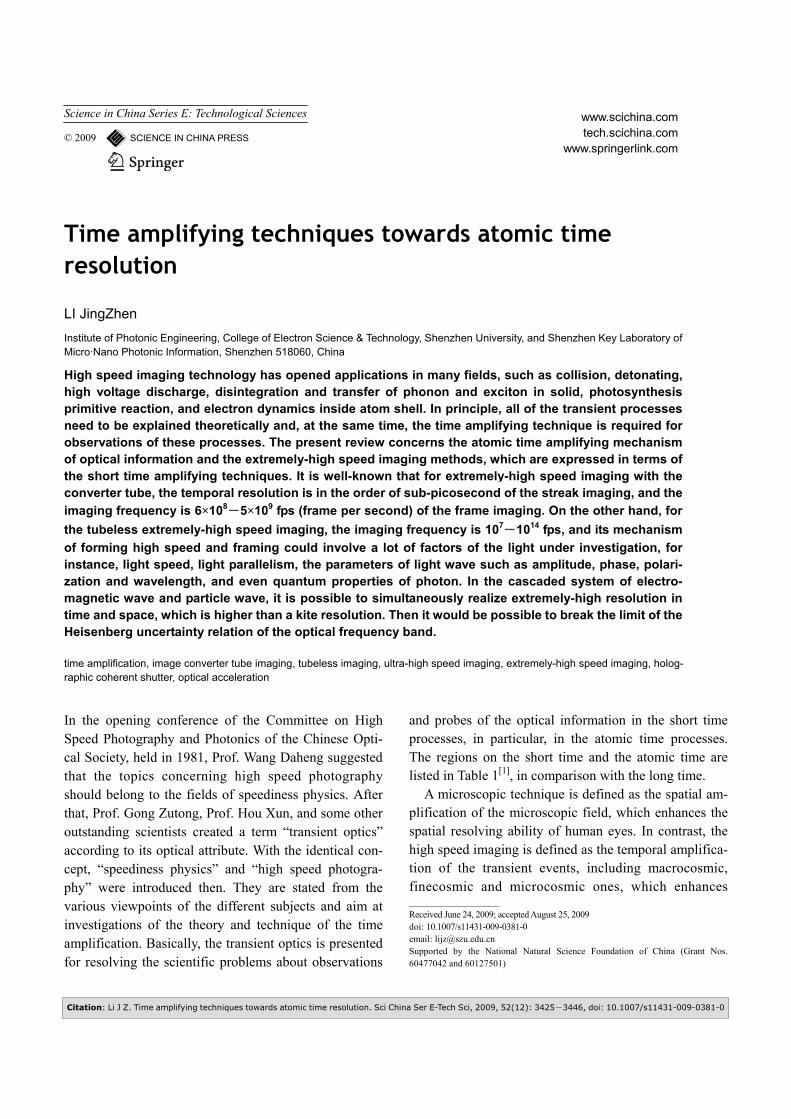
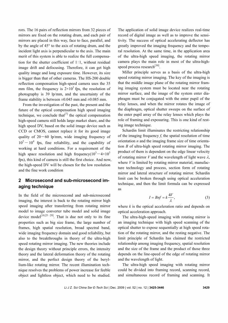
2.1.1 Synchronous framing technique. The key points of Miller theory as a basis of the rotating mirror frame imaging are: the second image plane should be close to the rotating mirror, the entrance pupil conjugates the entrance pupil of the relay lens after passing through the rotating mirror, and the optical shutter carries out the exposing and the framing during the scanning of rotating mirror. The so called synchronization means both the imaging beam reaching the film and the triggering pulse reaching the target under study at the same time, for re-cording the transient process. In the Miller imaging technique, there is still room for further development such as big size frame, more information, broader spec-trum and real time recording of digital image. The re-searchers in the US and Holland have successfully de-veloped the Grandaris 128 microscopic ultra-high speed camera with real time data output and imaging fre-quency of 2.5×10⁷ fps[29]. The China-made ZFK-2000 ultra-high speed camera has the imaging frequency of 2×10⁷ fps, as shown in Figure 2(a).
Figure 2 Synchronous high-speed camera. (a) Schematic figure of ZFK-2000 frame camera; (b) ZSK-30 Be rotating mirror scanning camera.
2.1.2 Synchronous scanning imaging technique. The lateral deformation and the driving power of a Be rotat-ing mirror in high-speed rotating are one tenth and one fourth of that of steel rotating mirror respectively. Therefore, the application of the Be rotating mirror and its performance index are the key landmark of evaluat-ing the level of synchronous scanning camera with ro-tating mirror. Of course, the technologic level of metal-lurgy, forging pressing, machining, rubbing and filming of Be rotating mirror can indicate the level and manu-facturing ability of this country. The ZSK-30 Be rotating mirror scanning camera, equipped with the nanosecond zero mark system which is two years earlier than ex-USSR, and made by Xi’an Institute of Optics and Precision Mechanics of CAS, has the scanning speed of 34 mm/μs and the equivalent relative aperture to the film of 7.75[31], as shown in Figure 2(b). Such technique and performance have attracted the attention of the in-ternational academe[25]. The 132 Be rotating mirror scanning camera with the scanning speed of 30 mm/μs and the equivalent relative aperture to the film of 11 has been made by USA.
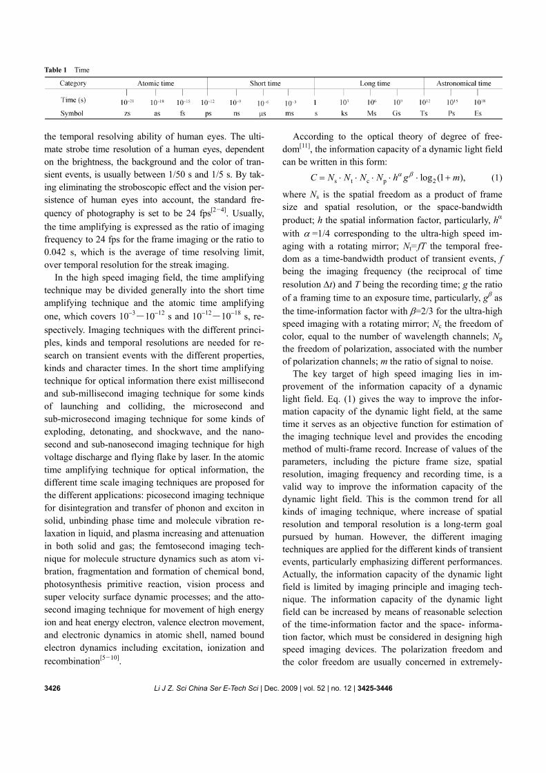
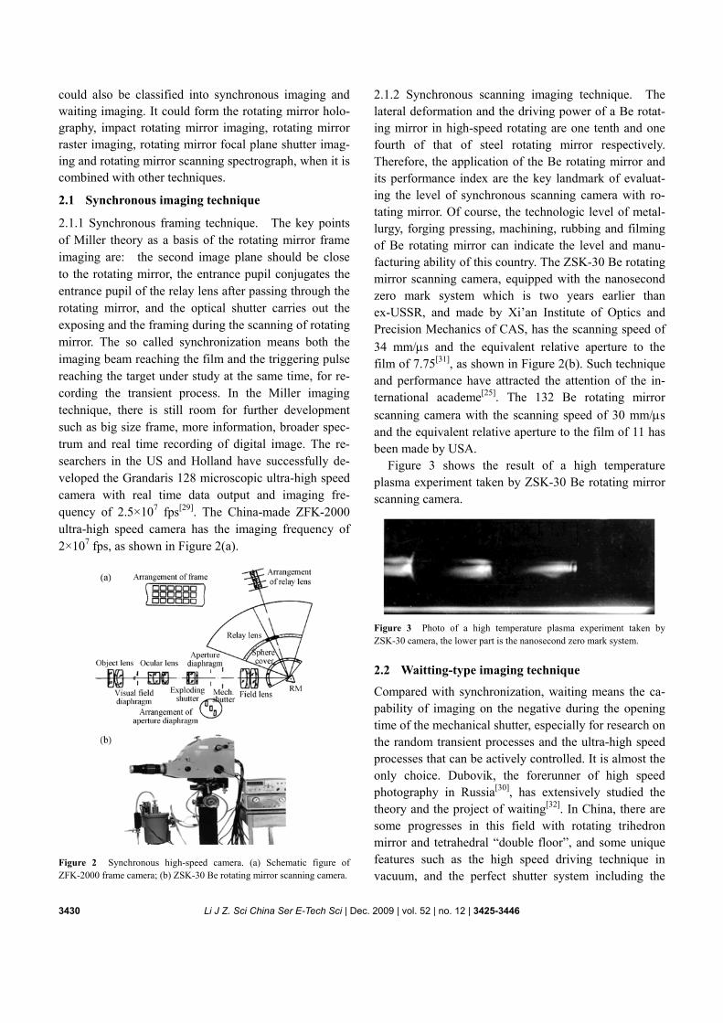
Figure 3 shows the result of a high temperature plasma experiment taken by ZSK-30 Be rotating mirror scanning camera.
Figure 3 Photo of a high temperature plasma experiment taken by ZSK-30 camera, the lower part is the nanosecond zero mark system.
2.2 Waitting-type imaging technique
Compared with synchronization, waiting means the ca-pability of imaging on the negative during the opening time of the mechanical shutter, especially for research on the random transient processes and the ultra-high speed processes that can be actively controlled. It is almost the only choice. Dubovik, the forerunner of high speed photography in Russia[30], has extensively studied the theory and the project of waiting[32]. In China, there are some progresses in this field with rotating trihedron mirror and tetrahedral “double floor”, and some unique features such as the high speed driving technique in vacuum, and the perfect shutter system including the
Li J Z. Sci China Ser E-Tech Sci | Dec. 2009 | vol. 52 | no. 12 | 3425-3446 3431
millisecond level mechanical shutter with the microsec-ond level fast-opening shutter driven by electric surges, and the microsecond level exploding shutter.
The ultra-high speed camera with the frequency of 2.5×10⁶ fps, which was made by Zhejiang University, has successfully recorded blasting instants of strong detonation tests for many times, and provided gold pic-ture data.
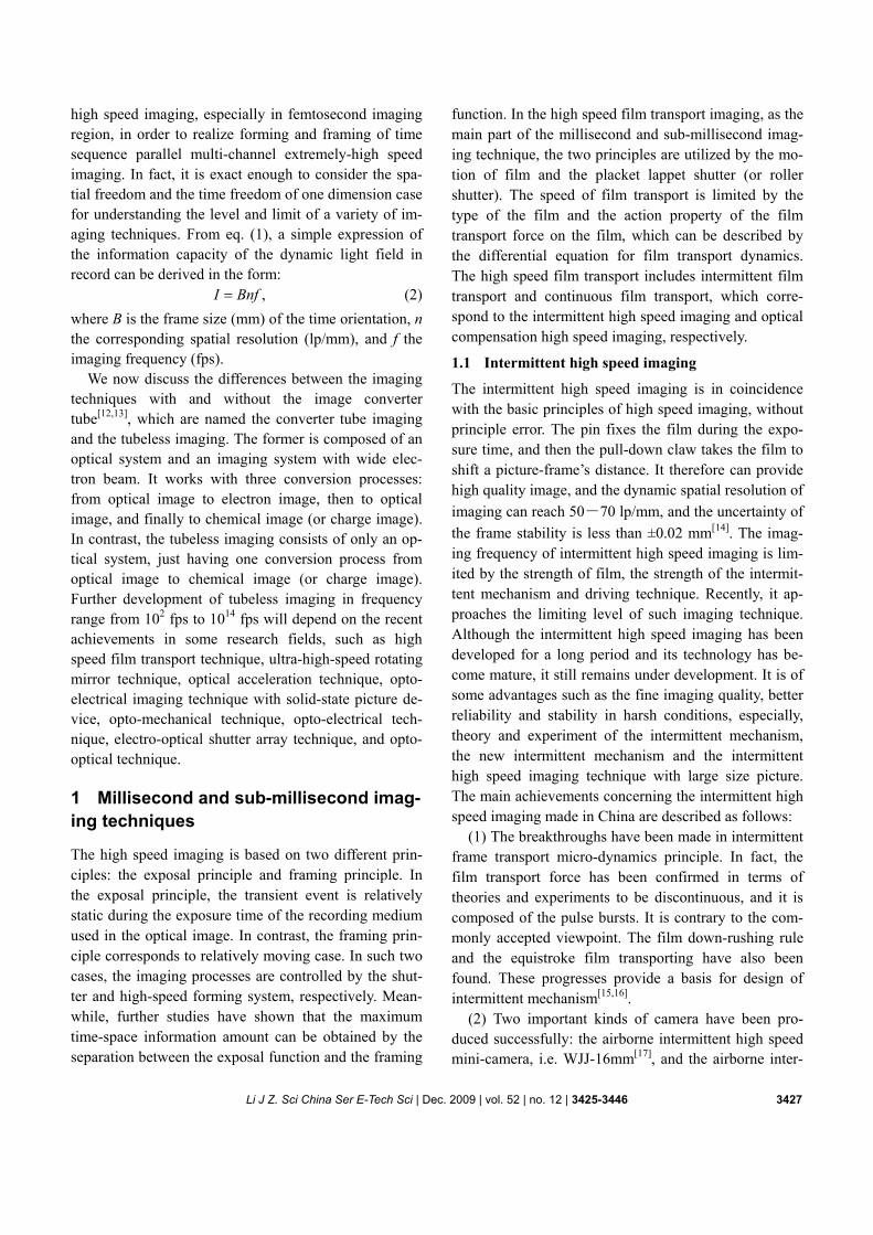
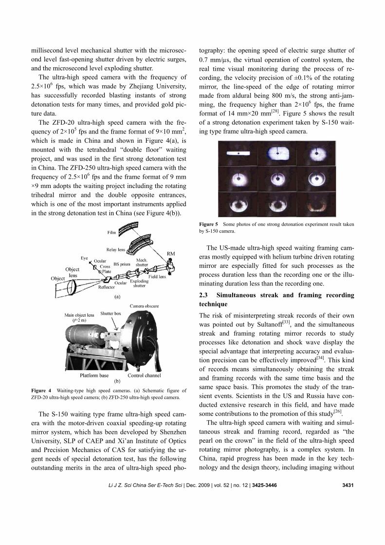
The ZFD-20 ultra-high speed camera with the fre-quency of 2×10⁵ fps and the frame format of 9×10 mm2, which is made in China and shown in Figure 4(a), is mounted with the tetrahedral “double floor” waiting project, and was used in the first strong detonation test in China. The ZFD-250 ultra-high speed camera with the frequency of 2.5×10⁶ fps and the frame format of 9 mm ×9 mm adopts the waiting project including the rotating trihedral mirror and the double opposite entrances, which is one of the most important instruments applied in the strong detonation test in China (see Figure 4(b)).
Figure 4 Waiting-type high speed cameras. (a) Schematic figure of ZFD-20 ultra-high speed camera; (b) ZFD-250 ultra-high speed camera.
The S-150 waiting type frame ultra-high speed cam-era with the motor-driven coaxial speeding-up rotating mirror system, which has been developed by Shenzhen University, SLP of CAEP and Xi’an Institute of Optics and Precision Mechanics of CAS for satisfying the ur-gent needs of special detonation test, has the following outstanding merits in the area of ultra-high speed pho-
tography: the opening speed of electric surge shutter of 0.7 mm/μs, the virtual operation of control system, the real time visual monitoring during the process of re-cording, the velocity precision of ±0.1% of the rotating mirror, the line-speed of the edge of rotating mirror made from aldural being 800 m/s, the strong anti- jam-ming, the frequency higher than 2×10⁶ fps, the frame format of 14 mm×20 mm[28]. Figure 5 shows the result of a strong detonation experiment taken by S-150 wait-ing type frame ultra-high speed camera.
Figure 5 Some photos of one strong detonation experiment result taken by S-150 camera.
The US-made ultra-high speed waiting framing cam-
eras mostly equipped with helium turbine driven rotating mirror are especially fitted for such processes as the process duration less than the recording one or the illu-minating duration less than the recording one.
2.3 Simultaneous streak and framing recording technique
The risk of misinterpreting streak records of their own was pointed out by Sultanoff[33], and the simultaneous streak and framing rotating mirror records to study processes like detonation and shock wave display the special advantage that interpreting accuracy and evalua-tion precision can be effectively improved[34]. This kind of records means simultaneously obtaining the streak and framing records with the same time basis and the same space basis. This promotes the study of the tran-sient events. Scientists in the US and Russia have con-ducted extensive research in this field, and have made some contributions to the promotion of this study[26].
The ultra-high speed camera with waiting and simul-taneous streak and framing record, regarded as “the pearl on the crown” in the field of the ultra-high speed rotating mirror photography, is a complex system. In China, rapid progress has been made in the key tech-nology and the design theory, including imaging without
3432 Li J Z. Sci China Ser E-Tech Sci | Dec. 2009 | vol. 52 | no. 12 | 3425-3446
principle defocusing, co-axis imaging of each relay lens, recording in uniform frequency and little lateral defor-mation of the rotating mirror not made from beryllium. The SSF simultaneous streak and framing recording system being manufactured in China, realized the plane optical path with the inclined beam incidence, and has fine qualities with the frequency of 2.2×10⁶ fps―5×10⁶ fps and the scanning speed of 16 mm/μs.
2.4 Optical accelerating technique
Achievements of the optical accelerating technique have promoted developments of the microsecond and sub- microsecond imaging technique and increased the im-aging frequency greatly. The galvanometer deflection type camera, based on the optical accelerator with the wedge-gap shape retroreflector, is an important break-through in the rotating mirror imaging field and has a lot of excellent merits: high sensitivity, broad linear dy-namic region, fine spatial contrast, high temporal resolu-tion, large information capacity and good adaptability[12]. The key of the accelerating is N time reflecting of the imaging beam and its deflecting velocity is 2N-fold of previous ones. The optical accelerator with the wedge-
gap shape retroreflector is a combination of the moving mirror and the static mirror, or the double mirrors in opposite directions. Both the moving mirror and the static mirror have the reflectivity of more than 99% for λ=0.532 μm and the face shape error of less than λ/4. Meanwhile, the combination of polyhedron mirrors and static mirrors can lead to a lot of projects with different accelerating ratios[13]. The research on this field is in the early stage in China.
The deflecting amplification is a new optical deflect-ing technique that is to amplify the deflecting angle, continuously or discretely. The imaging frequency of this kind of imaging technique which is now processed with advantage of nanosecond imaging field, can reach above 107―108 fps.
2.5 Some achievements in the field of microsecond and sub-microsecond imaging in China
In order to meet the demand of improving the level of strategic weapon test and modern scientific research, the research of the microsecond and sub-microsecond im-aging technique with rotating mirror has attracted great attention all along in China. Under the extended research and development of this kind of imaging technique, some vivid characteristics and special systems have been
formed. (1) A set of technologies of manufacturing the Be ro-
tating mirror have been developed and this kind of mir-ror has been successfully applied to the ultra-high speed rotating mirror camera.
(2) A set of technologies of manufacturing the aldural rotating mirror have been developed and this kind of rotating mirror has been successfully applied with the margin line speed of 800 m/s[35,36], which have not been reported in the other countries so far.
(3) In case of costliness and venomousness of the Be rotating mirror, the rotating mirror mechanism made from a non-Be material whose lateral deformation is the same as the Be rotating mirror has been developed[37].
(4) The designing, machining, assembling and appli-cation of the high velocity motor driven coaxial rotating mirror mechanism have formed the Chinese characteris-tics of driven technique, whereas in the US, the air im-peller is mainly adopted[28].
(5) The electric surge shutter with the opening speed of 0.7 mm/μs, no pollution of spatter and fragment, low voltage[38] is better than the shutter with the opening speed of 0.59 mm/μs reported by the US Patent Bureau.
(6) The complete and valuable equations[27] for imag-ing without principle defocusing, co-axis imaging of each relay lens, recording in uniform frequency, instead of the classic design theory, have been deduced, and applied to the design of SSF camera. The non- redun-dancy designing theory for improving the space-time information of camera has been successfully applied to the S-150 camera.
(7) The nanosecond zero mark system which was de-veloped two years earlier than ex-USSR has been ap-plied to the ZSK-30 Be rotating mirror scanning camera. The theory and the design of non-defocusing with the compensation of movement[39] are cited and developed by Egel[30].
3 Microsecond and sub-microsecond imaging with solid-state picture device
The solid-state picture device, including CCD and CMOS, is an array device within which optical image is translated into one-dimensional time sequence electronic output signals. With the development of solid-state pic-ture device, it has been used more and more widely in the field of high speed imaging, and becomes the chal-lenger of silver film as record medium. However it is
Li J Z. Sci China Ser E-Tech Sci | Dec. 2009 | vol. 52 | no. 12 | 3425-3446 3433
restricted by the essential limit of the electronic bottle-neck (electronic technique such as charge transportation frequency, charge storage and so on) for getting bigger space-bandwidth product and time-bandwidth product.
3.1 CCD imaging device
3.1.1 Spatial resolution of array imaging device. The spatial resolution of array imaging device depends not only on the pixel shape and its structure but also on the relative motion state between the target and the imaging device and the adopted wavelength. In general, the static optical resolution (N0) can be expressed by N0=1/2a for
the pixel shape of square and ( )0 1/ 3N a= for the
pixel of hexagon. However, for the motion state, the dynamic optical resolution limit D
0N is independent of
the pixel shape and D0 1.22 / .N a=
On the other hand, the transfer property of array im-aging device is directly related to the wavelength. The amplitude of this frequency component decreases as Gauss function in the visible region, and as the inverse proportion function in the infrared. The frequency con-trast function can be well approximated by the square sinc function. The width of half peak value of array CCD is 1.5 times of the distance between adjacent pixel in the visible region, and is 2 times in the infrared[40].
3.1.2 Main properties of a professional-quality CCD. The main properties of a professional-quality CCD are as follows: the pixel range covers from 512×512 to 5120×5120, and filling factor is 100% (no dead area between pixel), the size of pixel covers from less than 6.8 μm×6.8 μm to 27 μm×27 μm. If the quanta effi-ciency (QE) is 70%, the detective sensitivity of CCD refrigerated with liquid nitrogen is 6 photons per pixel. Until now the dynamic range, defined as the ratio of maximum and minimum signal that can be detected, is 6×10⁴:1, which far exceeds the dynamic range of pho-tography film (103:1).
3.2 Solid-state picture device in the ultra-high speed imaging technique
How to apply the solid-state picture device into the ul-tra-high speed imaging and even the extremely-high speed imaging is always an important problem. Obvi-ously, the parallel read-out technique cannot reach the imaging frequency of 105―107 fps[41,42]. A new tech-nique has been founded out. Now, there are two ap-
proaches. One is using the solid-state picture device only as record material which plays the role of framing and forming of ultra- or extremely-high speed by means of the optical principles. The other is using the solid-state picture device as both recording and framing at the same time, named the in-situ storage (ISIS) technique of CCD.
The imaging frequency of CCD of the in-situ storage can reach 106 fps, and the number of digital images re-corded is about 100 frames. The key is the manufacture of CCD chip, which uses parallel reading and ISIS with image pixel shift. The so called ISIS is “local storage” or “local memory”, which means one frame can be stored after shifting only a pixel distance.
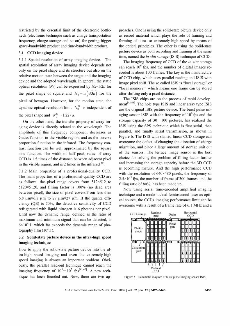
The ISIS chips are on the process of rapid develop-ment[43,44]. The hole type ISIS and linear array type ISIS are the original ISIS picture device. The burst pulse im-aging sensor ISIS with the frequency of 106 fps and the storage capacity of 30―100 pictures, has realized the ISIS using the SPS technique which is first serial, then parallel, and finally serial transmission, as shown in Figure 6. The ISIS with slanted linear CCD storage can overcome the defect of changing the direction of charge migration, and place a large amount of storage unit out of the sensors. The terrace image sensor is the best choice for solving the problem of filling factor further and increasing the storage capacity before the 3D CCD is becoming mature. And the high performance CCD with the resolution of 640×480 pixels, the frequency of 2.5×10⁵ fps, the number of frame of 300 frames, and the filling ratio of 80%, has been made up.
Now using serial time-encoded amplified imaging technique and a mode-locked femtosecond laser as opti-cal source, the CCDs imaging performance limit can be overcome with a result of a frame rate of 6.1 MHz and a
Figure 6 Schematic diagram of burst pulse imaging sensor ISIS.
3434 Li J Z. Sci China Ser E-Tech Sci | Dec. 2009 | vol. 52 | no. 12 | 3425-3446
shutter speed of 440 ps by mapping a two-dimensional (2D) image into a serial time-domain data stream, si-multaneously the image in the optical domain can be amplified, and an entire 2D image can be captured by using a single-pixel photodetector[45].
4 Extremely-high speed imaging tech- nique with an image converter tube[46―49]
The image converter tube, as the important means of the picosecond and femtosecond imaging techniques, is a kind of the wide electron beam imaging device com-posed of a photoelectric cathode, an electron optics sys-tem, a phosphor screen, and an imaging system. The imaging process of the tube in this way is that the elec-tron image transformed from the optical image through the cathode is imaged on the screen through the electron optics system and the deflecting system and translated into the visible optical image, and finally is translated into the chemical image or the charge image by the im-aging system. The imaging technique with the image converter tube, divided into the framing technique and the streak technique, has long been developed with its own features and system in China, and there is almost no gap compared to the world level.
There are many advantages of this kind of imaging such as realizing light wavelength transition of the in-frared, the ultraviolet, and the X-ray images into the visible images by means of the different cathodes, en-hancing the illuminance up to Maga-fold for some fee-ble imaging, carrying through the extremely-high speed imaging. In the present, in this imaging, the single frame exposure time can reach 45 ps, the multi-frame imaging frequency 6×10⁸―5×10⁹ fps, and the temporal resolu-tion of the streak imaging 10−13 s for the synchroscan model 280 fs. However both the space-bandwidth product and the frame number are limited by electron optics imaging system and electron deflexion system[49].
4.1 Framing imaging technique with the framing tube
The framing imaging with the tube, the main perform-ance indices of which include the exposure time, the imaging frequency, the dynamic spatial resolution, the frame number and the frame format, means getting a series of two-dimensional frames with time discontinu-ity and at different exposal centers on the screen. The key technique for imaging is how to make framing and
forming of the time sequence shutters with ex-tremely-high speed, and hereby can be divided into the framing with the voltage gating, the framing with the electron beam scanning and that with the sampling scanning. So far, the shortest exposure time is around 35 ps, and the frequency for the multi-frame imaging is 6×10⁸―5×10⁹ fps.
4.1.1 MCP (micro-channel plate) gated framing imag-ing. The superiority of this kind of imaging consists in the exposure time of 100 ps, the more frame, the bigger dynamic region, the higher sensitivity, and the stronger anti-jamming. The X-ray camera with the temporal resolution of ps is composed of the pinholes for imaging the MCP gated framing tube, the high voltage pulse generator with picosecond level, and the picture re-cording setup. MCP and the phosphor screen form the proximity focusing device. Its input surface coated with the multi-channel microstrip of transmission line is the golden photoelectric cathode, and the target is imaged on the different locations of the microstrips with multi- pictures through the array pinhole. When the picosecond high voltage pulse passed through the microstrip, each image location goes through different gain gating time to form a series of time sequence two-dimensional image. In general, its exposure time is less than the gated pulse width, its imaging frequency is dependent on the gated pulse transmission rate on the microstrip and the dis-tance of two adjoined imaging locations, and its spatial resolution depends on the pinhole and MCP.
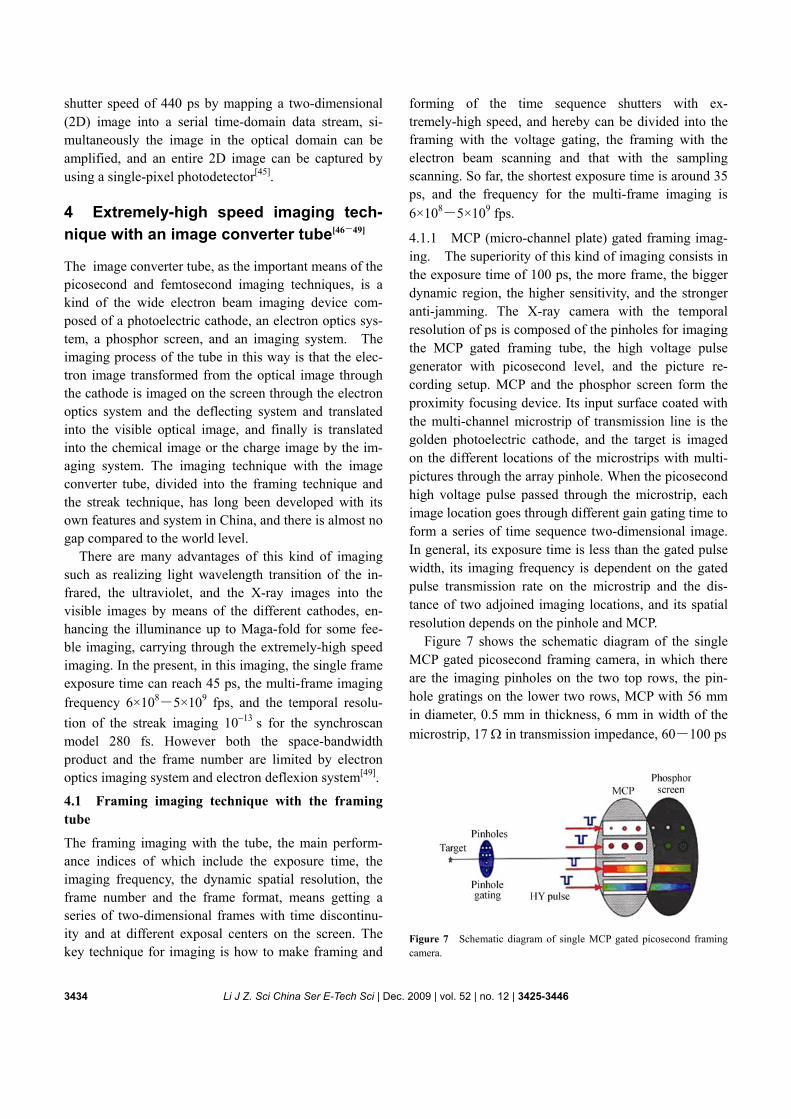
Figure 7 shows the schematic diagram of the single MCP gated picosecond framing camera, in which there are the imaging pinholes on the two top rows, the pin-hole gratings on the lower two rows, MCP with 56 mm in diameter, 0.5 mm in thickness, 6 mm in width of the microstrip, 17 Ω in transmission impedance, 60―100 ps
Figure 7 Schematic diagram of single MCP gated picosecond framing camera.
Li J Z. Sci China Ser E-Tech Sci | Dec. 2009 | vol. 52 | no. 12 | 3425-3446 3435
in the exposure time dependent on the gain. The double thin MCP (0.5 mm in thickness of each MCP) gated technique can make the exposure time from 60 ps to 35 ps, which is the best result in the world now[47].
4.1.2 Electron beam scanning framing imaging. The framing and shuttering of this imaging have been com-pleted by three pair deflecting plates behind the focusing system. The first pair deflecting plate, behind which there is the slit diaphragm, can play the role of shutter-ing. The second pair plate can compensate the lateral velocity difference of each part of the picture induced by the first plate through the same scanning rate, the same sensitivity, the same amplitude of the sine wave, and the opposite scanning direction and different phases, be-tween the first plate and the second plate, in order to get the sharp and stable pictures. The direction of the step voltage on the third pair plate is perpendicular to that on the first and second plates for framing. If more frames are required, it is necessary to increase the number of the slit.
Using this kind of imaging technique, it is successful to manufacture the picosecond X-ray framing camera with the typical experiment results such as three-step exposure times of 75, 145, 220 ps, the dynamic spatial resolution of more than 6 lp/mm on the cathode, 3 frames, three-step framing times of 300, 570, 870 ps. From the imaging principle of this imaging technique, it is hard to reach the spatial resolution of ten and several picometers, and the temporal resolution of ten and sev-eral picoseconds[50].
4.1.3 Sampling scanning framing imaging. This kind of imaging technique can be divided into the multi-picture slit sampled scanning framing technique and the picture disassembled scanning framing tech-nique. This two framing techniques are hard to meet the condition of the sampling theorem, and belong to the undersampling, thus limiting the spatial resolution and the space-bandwidth product. Therefore it is necessary to reconstruct images. However using the sampling concept and the interval between sampling points, we can improve the recording results for higher spatial resolution and more pictures, and longer exposure time (as high as that of the streak imaging).
The multi-picture slit sampled scanning framing technique can be defined, that is, the multipictures of the target are imaged on the different places of the slit on the cathode by the one-dimensional multi-channel pin-
hole and the array pinhole line is tilted with a little angle, e.g. 5.2° relative to the slit line to realize the one- dimen-sional sampling code of two-dimensional picture be-cause of the different places of the slit having sampled the different places of the picture. Because the scanning of the image converter tube can record the sets of the different time pictures, the framing and the exposure functions can be realized, and a series of time sequence two-dimensional images can be obtained through recon-struction. The experiment results with the exposure time of 11.7 ps, the spatial resolution of 14.9×15.8 μm (hori-zontal and vertical), and 10 frames, have been obtained through the pinhole of 11.6 μm in diameter and the in-terval of 150 μm of two close pinholes[51]. However, the picture is not full because of the pinhole itself and the imaging principle.
The picture disassembled scanning framing technique can realize the framing and the exposure functions while the two-dimensional sampling array of the picture on the cathode can be scanned for a little distance by the image converter tube in the scanning state, and then the picture sets of multipictures are obtained, and need to be recon-structed. Meanwhile, the reconstruction can be easily realized by the computer when the CCD is used to re-cord the digital picture sets. The essential of this kind of imaging is the combination of the picture dissembled principle with the scanning imaging to reach higher im-aging frequency. Nevertheless, there is the same expo-sure time as framing time and the space-bandwidth product limited by the cathode area and its spatial reso-lution. Now the experiment results with the exposure time of 7 ps, the spatial resolution of 3.5 lp/mm on the cathode and 16 frames, have been obtained in China[52]. This kind of imaging, more perfected, can obtain better pictures, more spatial information and more frames, than those of the multi-picture slit sampled scanning framing.
According to the actual technical level, with the sam-pling scanning framing imaging technique it would be difficult to reach higher space-bandwidth product, nor more frame number. However, the perfect performances including the imaging frequency of 108 fps, the exposure time of 3 ns, the spatial resolution of 15 lp/mm and 8 frames, can be reached by means of using the optical methods for framing, 8 framing tubes for imaging, and 8 CCD devices for reading out and recording[53].
4.2 Streak imaging technique with scanning tube
The streak camera with the tube, the main performances
3436 Li J Z. Sci China Ser E-Tech Sci | Dec. 2009 | vol. 52 | no. 12 | 3425-3446
of which are the temporal resolution and the dynamic region, is composed of the optical system, the scanning converter tube, the control circuit and the readout system, and can present one- dimensional varying picture of tar-get with time.
The temporal resolution would be defined as the re-solving power of the shortest time interval of two ad-joining time states, which is subject to the spatial resolu-tion of the scanning tube, the scanning voltage slope, the sensitivity of the deflecting plate and the bandwidth, and also to the response time of the cathode, the time disper-sion of photoelectron transition and the space charge effect. Its theoretical temporal resolution is 10 fs[54]. The temporal resolution of this tube has gone through mi-crosecond, nanosecond, picosecond and femtosecond steps. Although some designs and justifications have demonstrated that it could reach to100, 70, 50 fs, or even shorter[47,55], the experimental result of the temporal resolution is pacing up and down between 100 fs and 200 fs, and so far, its best recording is 180 fs[56].
The temporal resolution of the synchroscan model of the streak imaging is less than that of the single-scan model because of the scanning parameter drift induced by some noise fluctuation owing to the scanning image overlaid by a great deal of events for the synchroscan, and the actual best one is 280 fs[57]. The progressing slowness of the temporal resolution of femtosecond is directly determined by the space-charge effect of the photoelectron beam bunches, which would be solved by the dynamic electron optics of the time dependent elec-tric field[58].
There are some definitions of the dynamic region of the image converter tube camera. As a rule, it is defined by the ratio of the input intensity which can make the pulse width spread by 10% to noise intensity on the re-cording medium, and the dynamic region is between some tens and some hundreds depending on the detected target.
The developing trend of the streak imaging technique with the scanning tube is that for the detecting wave-band it will extend to near and middle infrared band, ultraviolet band, X-ray band and neutron band, for the detecting parameter it will develop towards the multi-dimensional aspect to simultaneously measure the temporal information, the spatial information and the spectrum information, and to spread the dynamic region, that is a long-term subject.
5 Tubeless extremely-high speed imag-ing technique
With the requirements of scientific researches at the ut-termost condition and for the finecosmic and the micro-cosmic ultra-high speed processes, the extremely-high speed imaging with the imaging frequency region being 107―1015 fps, or higher, is now being taken into con-sideration. So far, although the image converter tube technique itself would be difficult to break through 109 fps, the frequency of 1010 fps can be reached by means of the picture disassembled principle. Moreover, this technique itself is also difficult to reach more frames and higher imaging frequency, that is, the information ca-pacity would be limited. Therefore we should try to find some other ways to realize the extremely-high speed imaging, for example using the light itself special prop-erties to record light itself information, among which the tubeless extremely-high speed imaging has attracted people’s attention[12,13].
Light radiation has the twoness that it is not only the ultra-swift process information carrier, but also the re-source and method of studying the ultra-swift process, and the optical phenomena in the ultra-swift process can be studied using the light beam itself. Forming tubeless extremely-high speed imaging should depend on the application of such resources as light velocity and pho-ton itself, and its amplitude, phase, and polarization, and wavelengths of light, even the quantum property of photon, in addition, depends on the latest achievements of opto-machinery, opto-electrical, electro-optical, and opto-optical technologies. As to the tubeless ex-tremely-high speed imaging, its forming principles and technologies are as follows.
(1) Picture disassembled technique. Using the rotating mirror technique, the imaging frequency can reach to 109―1010 fps; using the image converter technique the frequency can reach to 1010―1011 fps. And the CCD of 5120×5120 pixels creates good condition for reconstruc-tion of the time sequence images with high quality.
(2) Array stroboflash source technique with picosec-ond level. It can form the multi-frame record with higher than 1010 fps, and its key technology is the combination of the electro-optical deflection (electro-optical crystal and electro-optical phase control wave-guide array) and Cranz-Schardin imaging system. It is noticeable that there has been the crystal scanning camera with the
Li J Z. Sci China Ser E-Tech Sci | Dec. 2009 | vol. 52 | no. 12 | 3425-3446 3437
temporal resolution of 20 ps[59]. (3) Ultra-high speed array shutter technique. It is the
time sequence electricity-induced nonlinear effect de-vice and light-induced effect device, e.g. Kerr cell, the imaging frequency is above 108―1014 fps. And this technique is related to the pulse width, the relaxation time of nonlinear materials, the delay time and its preci-sion.
(4) Holographic transient coherent shutter technique (coherent gated technique). It can reach 1014 fps, even higher. This technique can realize extremely-high speed imaging with the extremely-high frequency by using the light itself property.
(5) Extremely-high speed imaging by hologram tech-nique. The author thinks that it uses the light itself prop-erty, “fast” and “coherent gated”, which is the main field of extremely-high speed imaging.
5.1 Picture disassembled principle and Cranz- Schardin imaging principle
The picture disassembled principle and Cranz-Schardin imaging principle are important and available to realize the ultra- and extremely-high speed imaging: the former is the evolvement of the sampling theorem, and the latter is the evolvement of the time sequence array parallel imaging system. Both of them are easy to do high speed and have the inherent information bottle-neck and some shortages
5.1.1 Picture disassembled principle. It is also named the master principle, or the sampling theorem, and one of its theoretical bases is that a band limited picture can be precisely expressed by a series of discrete values, or rather, the sampling frequency is twice that of the maximum band-limited frequency and at each sampling point is the right sample function when the sampling interval is the same. Obviously, the picture disassembled imaging principle is difficult to meet the condition of the sampling theorem; therefore, this principle is approxi-mate. However, this approximation is accepted for the high speed imaging system being a low pass filter since some factors will influence the picture quality.
Its other theoretical base is that the sampling interval and the sampling point size should be appropriately proportional, in this case multi-frame record can be formed. Usually framing can be realized and a frame of master picture can be obtained by shifting one pixel, and the exposure time equals the framing time. The picture
disassembled imaging can be recognized as the simulta-neous scanning result of a great deal of streak cameras (equal to pixel number), and the imaging frequency is the reciprocal of the temporal resolution
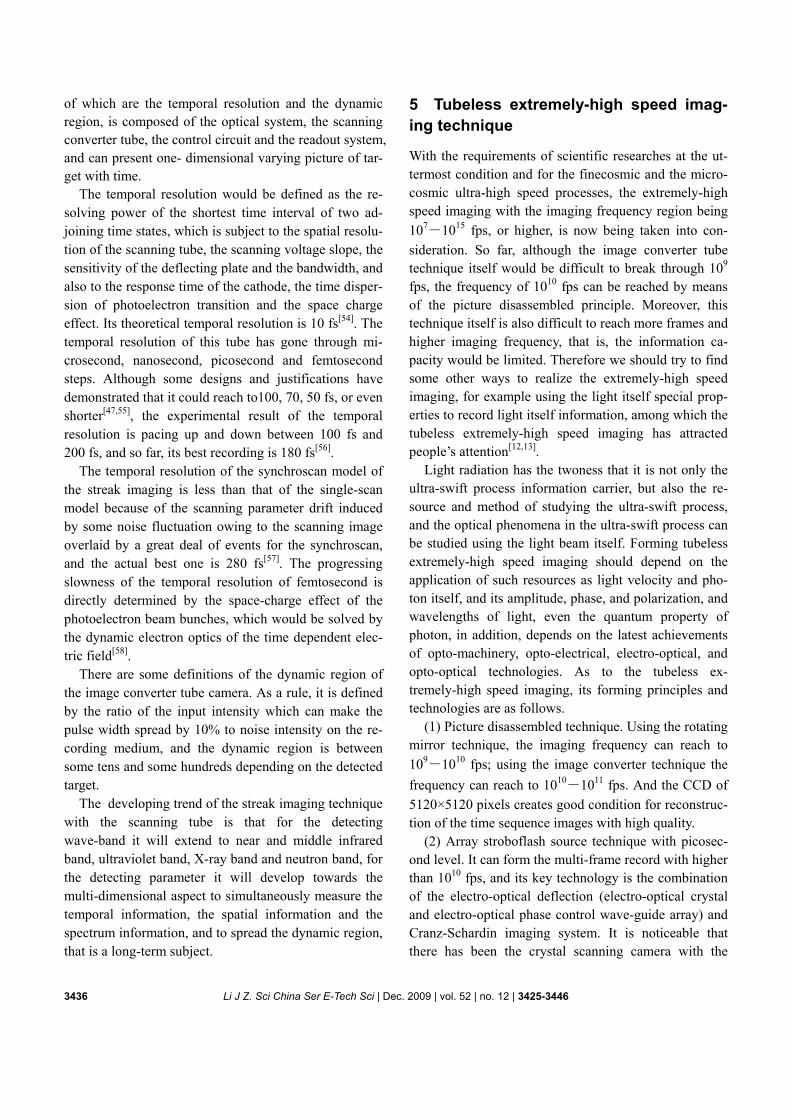
Calculation of main performance parameters in the picture disassembled imaging is shown in Figure 8 where s′ is the maximum distance of pixel scanning line, d is the distance of the two adjacent pixel scanning lines, he is the distance between two adjacent pixels. If step a is the movement distance of pixel which forms the mas-ter picture, for the microlens array board, the imaging frequency ν =V/a, the minimum step min 2 / 3a N= , and
the optimum pixel opt 1/ 2 ,Nδ = and the number of
frame C can be written as 2 sin / 1,ec h aaα ′= − (4) where V is scanning speed; N is the spatial resolution of this kind of imaging system which can be determined by experiments.
Figure 8 Multiple frame forming scheme of picture disassembled imaging.
Development of the picture disassembled board. The
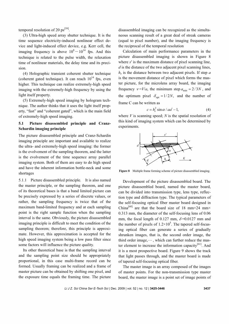
picture disassembled board, named the master board, can be divided into transmission type, lens type, reflec-tion type and diffraction type. The typical parameters of the self-focusing optical fiber master board designed in China[60] are that the board size of 18 mm×24 mm× 0.313 mm, the diameter of the self-focusing lens of 0.06 mm, the focal length of 0.127 mm, δ =0.0127 mm and the number of pixels of 1.2×10⁵. The tapered self- focus-ing optical fiber can generate a series of gradually shrunken images, that is, the second order image, the third order image, , which can further reduce the mas-ter element to increase the information capacity[61]. And it is a most prospective board. Figure 9 shows the track that light passes through, and the master board is made of tapered self-focusing optical fiber.
The master image is an array composed of the images of master points. For the non-transmission type master board, the master image is a point set of image points of
3438 Li J Z. Sci China Ser E-Tech Sci | Dec. 2009 | vol. 52 | no. 12 | 3425-3446
Figure 9 Master board made of tapered self-focusing optical fiber. (a) Single tapered self-focusing optical fiber; (b) master board. the exit pupil of the main objective through the mi-crolens array and is modulated by the object image in-tensity. The high speed scanning of the master image related to the recording medium can acquire multiframes of the master images. By the rotating mirror scanning and the electronic scanning, the imaging frequency can reach 109―1011 fps, and even higher.
Sultanoff realized the extremely-high speed photo- gaphy with the frequency of 108 fps and 150 frames by using slit transmission type master principle (the master image pixel is line, not point)[62]. It is the most original extremely-high speed photography to satisfy only some special requests, although its image quality is not good enough. In China, the imaging frequency of the picture disassembled imaging camera with the rotating mirror scanning, designed by Gong would reach to 5.1×10¹⁰
fps[61], and that with the electronic scanning has reach to 7.7×10¹⁰ fps[63].
The obtained result from this principle is a set of im-ages; therefore, it is necessary to get each image by means of the reconstruction. Developments of CCD and CMOS give this kind of imaging a new opportunity to develop. However it cannot reach a satisfying situation for the product of the space-bandwidth and the frame number because of manufacture technique of solid-state picture device (such as CCD and COMS).
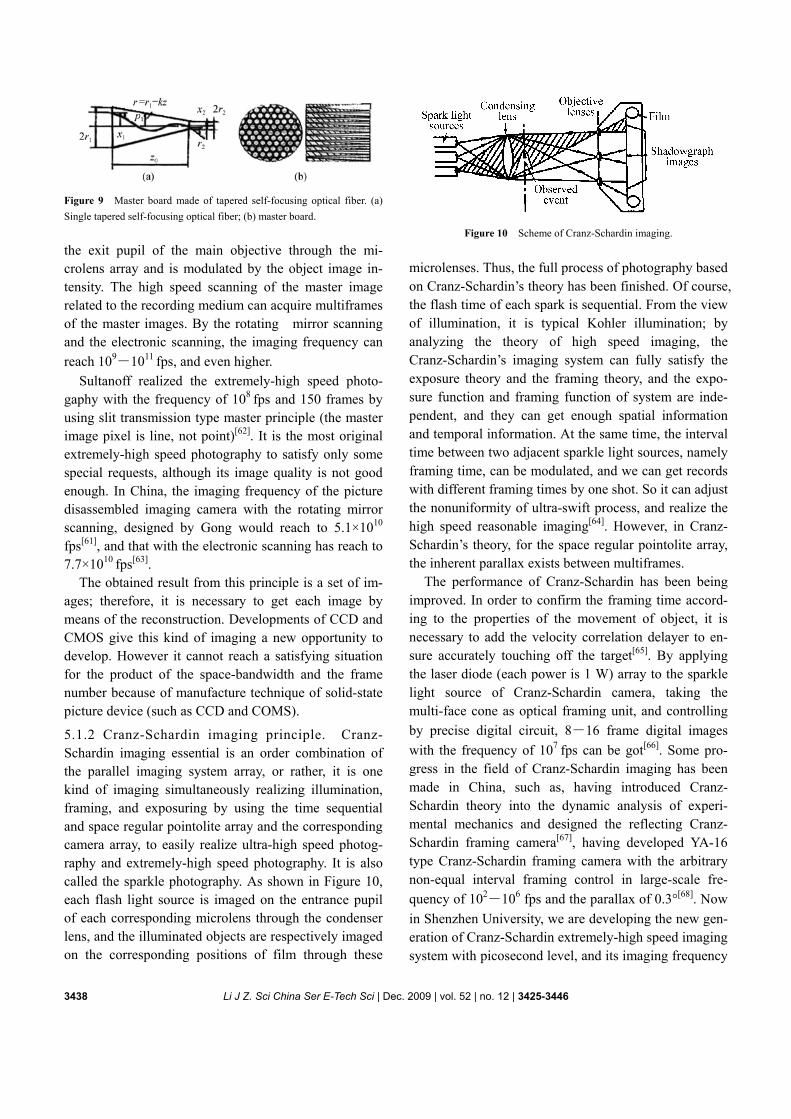
5.1.2 Cranz-Schardin imaging principle. Cranz- Schardin imaging essential is an order combination of the parallel imaging system array, or rather, it is one kind of imaging simultaneously realizing illumination, framing, and exposuring by using the time sequential and space regular pointolite array and the corresponding camera array, to easily realize ultra-high speed photog-raphy and extremely-high speed photography. It is also called the sparkle photography. As shown in Figure 10, each flash light source is imaged on the entrance pupil of each corresponding microlens through the condenser lens, and the illuminated objects are respectively imaged on the corresponding positions of film through these
Figure 10 Scheme of Cranz-Schardin imaging.
microlenses. Thus, the full process of photography based on Cranz-Schardin’s theory has been finished. Of course, the flash time of each spark is sequential. From the view of illumination, it is typical Kohler illumination; by analyzing the theory of high speed imaging, the Cranz-Schardin’s imaging system can fully satisfy the exposure theory and the framing theory, and the expo-sure function and framing function of system are inde-pendent, and they can get enough spatial information and temporal information. At the same time, the interval time between two adjacent sparkle light sources, namely framing time, can be modulated, and we can get records with different framing times by one shot. So it can adjust the nonuniformity of ultra-swift process, and realize the high speed reasonable imaging[64]. However, in Cranz- Schardin’s theory, for the space regular pointolite array, the inherent parallax exists between multiframes.
The performance of Cranz-Schardin has been being improved. In order to confirm the framing time accord-ing to the properties of the movement of object, it is necessary to add the velocity correlation delayer to en-sure accurately touching off the target[65]. By applying the laser diode (each power is 1 W) array to the sparkle light source of Cranz-Schardin camera, taking the multi-face cone as optical framing unit, and controlling by precise digital circuit, 8―16 frame digital images with the frequency of 107 fps can be got[66]. Some pro-gress in the field of Cranz-Schardin imaging has been made in China, such as, having introduced Cranz- Schardin theory into the dynamic analysis of experi-mental mechanics and designed the reflecting Cranz- Schardin framing camera[67], having developed YA-16 type Cranz-Schardin framing camera with the arbitrary non-equal interval framing control in large-scale fre-quency of 102―106 fps and the parallax of 0.3°[68]. Now in Shenzhen University, we are developing the new gen-eration of Cranz-Schardin extremely-high speed imaging system with picosecond level, and its imaging frequency
Li J Z. Sci China Ser E-Tech Sci | Dec. 2009 | vol. 52 | no. 12 | 3425-3446 3439
is as high as 1010 fps and the digital image is 8―16 frames.
5.2 Extremely-high speed imaging technique with time sequential array shutter
This kind of imaging technique is based on the devices manufactured by using the electro-optical nonlinear ef-fect and the light induced Kerr effect. Its shutter rate is very high related to the relaxation time of the nonlinear effect and the delay precision, and its imaging frequency could reach to 108―1014 fps.
Electro-optical polarizing framing device, composed of series of longitudinal operating KD*P and OE Glan- Foucault prism, is a core device possessing the optical rotation and the full polarizing beam-splitting features. The beam direction of transmission is deflected by the big angle according to the inner total reflection of OE prism, and its deflecting rate is dependent on the rate of the pulsed high voltage electric field. Using the time sequential array shutter technique of 8 EOFD devices, the imaging frequency of 2×10⁸ fps and 8 images have been obtained[69].
Under the effect of a giant laser pulse, CS2 liquid can create the Kerr effect which can be used to make the laser driven Kerr cell camera to freeze the green pulse propagation[70―72]. And adopting the steep front edge of the laser pulse can further shorten the shutter time. For the laser pulse with the width of 8 ps and the steep front edge time of 0.1―1ps, its shutter time is some 0.1―1 ps.
The limit of the shutter time is equal to the relaxation time of Kerr medium. For the femtosecond laser pulse, the relaxation time of CS2 medium is an obstacle to fur-ther shorten the shutter time; therefore, to seek after new mediums with shorter relaxation time is needed. The relaxation time of CCl4 is about 0.5 ps, and n2B=
21 2 20.36 10 m V ;−× that of optical glass BK7 is less
than 10 fs, and 22 2 22 2.18 10 m V .Bn −= × Obviously,
the nonlinear coefficients of the two kinds of medium are too small. However this kind of technique meets a new development opportunity: great progress of the mode-locked technique, the chirp technique, and other special laser technique to create the laser pulse as short as 130 as, as high in intensity as 1022 W/cm2, has offered the available precondition; meanwhile, the recent re-search indicates that using the charge transfer between molecules can realize resonance enhancing the three- order nonlinear effect by 2―3 orders[73], which would
be able to make the optical Kerr shutter array to be real-ized.
5.3 Holographic coherent shutter imaging technique
Holographic coherent shutter connotation is that if the optical path difference between the object light beam and the reference light beam is less than the coherent length, the coherent shutter is open with coherent re-cording; otherwise, if the difference is bigger than the length, the shutter is closed with no coherent recording. Here the coherent length ultra-short character of the ul-tra-short laser pulse is used to record the light-wave propagation process, which mostly shows that using the light itself character can realize the extremely-high speed imaging, and the frequency is limited by the laser pulse width.
According to Heisenberg uncertainty principle, which clarifies the connotation that it is impossible to simulta-neously precisely measure a pair of nonreciprocal ob-served physical quantity, the following relation for the pulse width τΔ and the spectral width νΔ can be ob-tained: ,kτ νΔ ⋅ Δ ≥ (5)
where k is a constant. According to Fourier analysis, k is related to shape of spectrum envelope: for ideal rectan-gular envelope k = 1, for Gaussian envelope k = 0.664 and for Lorentzian envelope k = 0.318. The ultra-short laser pulse width and its coherent time are of the same magnitude order, and the coherent length can be calcu-lated with product of light speed and coherent time. And now the ultra-short laser pulse has entered the attosec-ond domain.
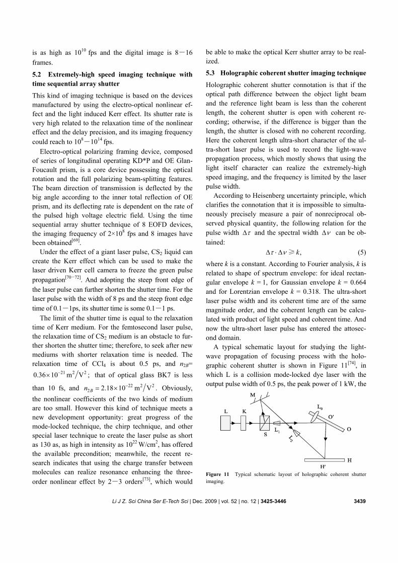
A typical schematic layout for studying the light- wave propagation of focusing process with the holo-graphic coherent shutter is shown in Figure 11[74], in which L is a collision mode-locked dye laser with the output pulse width of 0.5 ps, the peak power of 1 kW, the
Figure 11 Typical schematic layout of holographic coherent shutter imaging.
3440 Li J Z. Sci China Ser E-Tech Sci | Dec. 2009 | vol. 52 | no. 12 | 3425-3446
repetition rate of 100 MHz, the length of 0.632 μm, K is a mechanical shutter, S is a beam splitting unit and the ratio is changeable, L1 and L2 are bean expanders (30×), O is a diffuse reflection board with the area of 200 mm×249 mm including a lens L0, M is a mirror, and H is a holographic plate with the area of 90 mm×200 mm.
From the principle of holography, a hologram records merely a part of object that optical path differences be-tween the object light beams and the reference light beams are smaller than coherent length. If coherent length is very short, the part of object, the optical path difference of which is in range of coherent length, is only seen when reconstructing, namely the bright inter-ference fringe area with nearly-zero optical path differ-ence, which means that coherent length is nearly to zero, can be observed. And if sight is moved continuously from left to right along the film plane, propagation process of the light wave can be observed, from which the information about variations of the object can be acquired. In the experiment mentioned above, the imag-ing frequency is as high as 1012 fps, and 10 frame pic-tures have reconstructed the light-wave focusing propa-gation in which framing times are different and the framing time at focusing transient time is 1 ps. More-over, the frequency of 1010 fps was reached in Amer-ica[75], and the same light-wave propagation process was demonstrated by the Japanese scholars in 2004[76].
The opto-optical (all-light) extremely-high speed im-aging technique is capable of unifying the shuttering function (i.e. exposure function) and the framing func-tion. In essence, the recording process is a process of interference between object light and reference light. A femtosecond laser pulse moving along the film plane H carries through coherent pulse-gating, which acts as a extremely-high speed shutter. With further development of the attosecond laser pulse technique, it would be pos-sible to unify the highest temporal resolution and the highest spatial resolution through research in the micro-scopic field. The exposure time of the holographic co-herent shutter technique depends on the ultra-short laser pulse width, and the attainable imaging frequency is limited by the ultra-short laser pulse width, the interfer-ence fringe width and the spatial resolution of recording medium, and then the interference fringe width is related to wavelength and angle between object light and refer-ence light. With the actual techniques, the exposure time can reach up to 10−15 s, or even shorter, and the imaging
frequency can be as high as 1014 fps.
5.4 Extremely-high speed imaging technique with holography
The holographic extremely-high speed imaging (HEHSI) is the main field of all-light extremely-high speed imag-ing. The extremely-high speed with multiframes is real-ized by using the twoness of light and the multi- pa-rameter property of holographic recording, including the multi-frame forming mechanism and the high speed forming mechanism. The key of the former mechanism is how to make multiple frame encoding fit the ex-tremely-high speed imaging, and that of the latter mechanism is how to utilize the light beam parallel property and how to form the time delay between sub-light beams.
Hologram formation is the interaction result among the object beam, the reference beam and the recording medium and is a multi-parameter process in which the reference beam is a most active factor. In general, the key of extremely-high speed imaging is how to encode the reference beam, and how to realize multi-frame technique that the framing time is in the range of ps―fs. The coding resources of the reference beam are wave-length, amplitude, phase, polarization and the angle or orientation of incident. In the development history of dynamical hologram, these six coding methods have successively been applied to the recording of multi-frame holography[10]. At present, the main en-coded framing techniques applied to the extremely-high speed imaging emphasize particularly the following techniques:
(1) Grating orientation-framing technique. The coding framing is formed by using the difference of grating orientation, and the frequency is determined by the dif-ference of the delay time of each sub-light path, the up-per limit of the frequency is the reciprocal of the laser pulse width[77].
(2) Grating spectrum delay technique. Its framing is formed by using the spectrum components of grating, and the imaging frequency is determined by the differ-ence of each spectrum component delay, the upper limit is the reciprocal of the laser pulse width.
(3) Angle and orientation framing. It can be divided into the direction angle coding on the meridian plane and the bearing angle coding on the sagittal plane. The latter is also named the rotating angle coding. The fre-quency is calculated using the difference of each
Li J Z. Sci China Ser E-Tech Sci | Dec. 2009 | vol. 52 | no. 12 | 3425-3446 3441
sub-light beam delay, the upper limit is the reciprocal of the laser pulse width.
(4) Wavelength framing. Using the grating the collat-eral and apace-separated sub-light beams with different lengths can be formed, the frequency can be computed according to the optical path difference, and the upper limit is still the reciprocal of the laser pulse width.
5.4.1 Holographic multiple frame extremely-high speed imaging with angle and orientation coding. First of all, under the emulsion recording, the least direction angle
HθΔ for framing in the meridian plane and the least
bearing angle VθΔ for framing on the sagittal plane are given as follows, respectively:
( )1/ 2sr
2 cos , 2 / tg ,sin 2H V Hnd
λ θθ θ θ θ
ϕΔ = Δ = Δ (6)
where θs and θr are the incident angles of the object beam and the reference beam, respectively, 2ϕ is the angle between the object beam and the reference beam, λ is the wavelength in air, d is the thickness of holo-graphic recording medium, and n is the refractive index of the medium. In eq. (6), all the angles are measured in the medium. However, CCD can be only applied to re-cording the quasi on-axis hologram because its space bandwidth is far less than that of the emulsion.
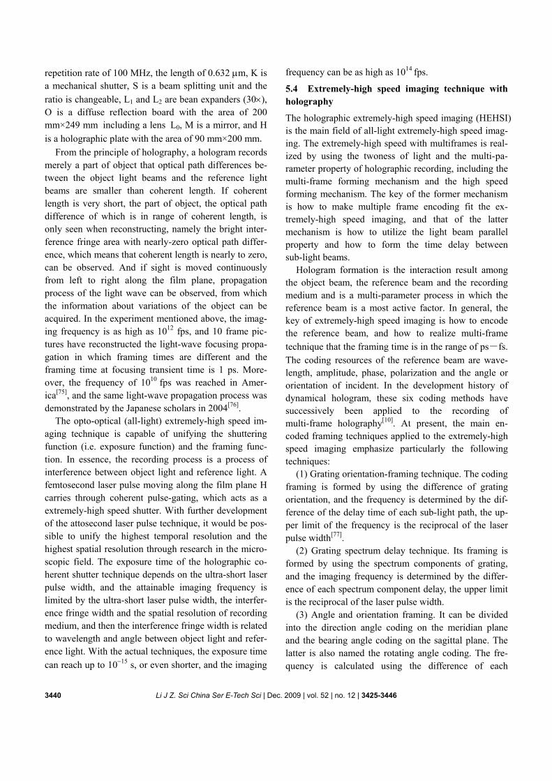
As is shown in Figure 12, there are 16 point light sources equally placed to make the bearing angle coding of the quasi on-axis holography. Experiments indicate that the on-axis lensless Fourier digital holography can to a great extent meet the requirements for the sampling condition of CCD, increase the object size studied and reduce the recording distance, thereby raise the defini-tion and the resolution of the reconstructed images. In these experiments, 4 frames, 8 frames, and 16 frames of the lensless Fourier on-axis hologram have been re-corded, respectively, and successfully reconstructed[78]. In this system there are two kinds of forming ex-tremely-high speed manner: one is the time sequential 16 point light sources with the framing time of picosec-ond order to form extremely-high speed recording with the frequency of 1010 fps, the other is the 16 point light sources provided with different phase units to form dif-ferent delaying times in which the smallest delay inter-val (the framing time) determines the highest frequency that could be 1014 fps order.
The digital quasi-on-axis holographic extremely-high speed imaging with the amplitude splitting and the
Figure 12 Scheme of on-axis lensless Fourier digital holography with the bearing angle coding.
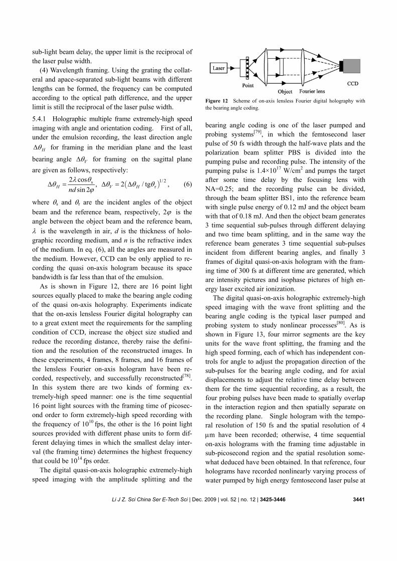
bearing angle coding is one of the laser pumped and probing systems[79], in which the femtosecond laser pulse of 50 fs width through the half-wave plats and the polarization beam splitter PBS is divided into the pumping pulse and recording pulse. The intensity of the pumping pulse is 1.4×10¹⁷ W/cm2 and pumps the target after some time delay by the focusing lens with NA=0.25; and the recording pulse can be divided, through the beam splitter BS1, into the reference beam with single pulse energy of 0.12 mJ and the object beam with that of 0.18 mJ. And then the object beam generates 3 time sequential sub-pulses through different delaying and two time beam splitting, and in the same way the reference beam generates 3 time sequential sub-pulses incident from different bearing angles, and finally 3 frames of digital quasi-on-axis hologram with the fram-ing time of 300 fs at different time are generated, which are intensity pictures and isophase pictures of high en-ergy laser excited air ionization.
The digital quasi-on-axis holographic extremely-high speed imaging with the wave front splitting and the bearing angle coding is the typical laser pumped and probing system to study nonlinear processes[80]. As is shown in Figure 13, four mirror segments are the key units for the wave front splitting, the framing and the high speed forming, each of which has independent con-trols for angle to adjust the propagation direction of the sub-pulses for the bearing angle coding, and for axial displacements to adjust the relative time delay between them for the time sequential recording, as a result, the four probing pulses have been made to spatially overlap in the interaction region and then spatially separate on the recording plane. Single hologram with the tempo-ral resolution of 150 fs and the spatial resolution of 4 μm have been recorded; otherwise, 4 time sequential on-axis holograms with the framing time adjustable in sub-picosecond region and the spatial resolution some-what deduced have been obtained. In that reference, four holograms have recorded nonlinearly varying process of water pumped by high energy femtosecond laser pulse at
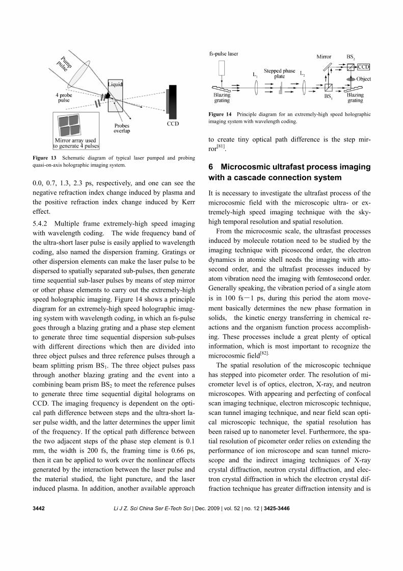
3442 Li J Z. Sci China Ser E-Tech Sci | Dec. 2009 | vol. 52 | no. 12 | 3425-3446
Figure 13 Schematic diagram of typical laser pumped and probing quasi-on-axis holographic imaging system.
0.0, 0.7, 1.3, 2.3 ps, respectively, and one can see the negative refraction index change induced by plasma and the positive refraction index change induced by Kerr effect.
5.4.2 Multiple frame extremely-high speed imaging with wavelength coding. The wide frequency band of the ultra-short laser pulse is easily applied to wavelength coding, also named the dispersion framing. Gratings or other dispersion elements can make the laser pulse to be dispersed to spatially separated sub-pulses, then generate time sequential sub-laser pulses by means of step mirror or other phase elements to carry out the extremely-high speed holographic imaging. Figure 14 shows a principle diagram for an extremely-high speed holographic imag-ing system with wavelength coding, in which an fs-pulse goes through a blazing grating and a phase step element to generate three time sequential dispersion sub-pulses with different directions which then are divided into three object pulses and three reference pulses through a beam splitting prism BS1. The three object pulses pass through another blazing grating and the event into a combining beam prism BS2 to meet the reference pulses to generate three time sequential digital holograms on CCD. The imaging frequency is dependent on the opti-cal path difference between steps and the ultra-short la-ser pulse width, and the latter determines the upper limit of the frequency. If the optical path difference between the two adjacent steps of the phase step element is 0.1 mm, the width is 200 fs, the framing time is 0.66 ps, then it can be applied to work over the nonlinear effects generated by the interaction between the laser pulse and the material studied, the light puncture, and the laser induced plasma. In addition, another available approach
Figure 14 Principle diagram for an extremely-high speed holographic imaging system with wavelength coding.
to create tiny optical path difference is the step mir-ror[81].
6 Microcosmic ultrafast process imaging with a cascade connection system
It is necessary to investigate the ultrafast process of the microcosmic field with the microscopic ultra- or ex-tremely-high speed imaging technique with the sky- high temporal resolution and spatial resolution.
From the microcosmic scale, the ultrasfast processes induced by molecule rotation need to be studied by the imaging technique with picosecond order, the electron dynamics in atomic shell needs the imaging with atto-second order, and the ultrafast processes induced by atom vibration need the imaging with femtosecond order. Generally speaking, the vibration period of a single atom is in 100 fs―1 ps, during this period the atom move-ment basically determines the new phase formation in solids, the kinetic energy transferring in chemical re-actions and the organism function process accomplish-ing. These processes include a great plenty of optical information, which is most important to recognize the microcosmic field[82].
The spatial resolution of the microscopic technique has stepped into picometer order. The resolution of mi-crometer level is of optics, electron, X-ray, and neutron microscopes. With appearing and perfecting of confocal scan imaging technique, electron microscopic technique, scan tunnel imaging technique, and near field scan opti-cal microscopic technique, the spatial resolution has been raised up to nanometer level. Furthermore, the spa-tial resolution of picometer order relies on extending the performance of ion microscope and scan tunnel micro-scope and the indirect imaging techniques of X-ray crystal diffraction, neutron crystal diffraction, and elec-tron crystal diffraction in which the electron crystal dif-fraction technique has greater diffraction intensity and is
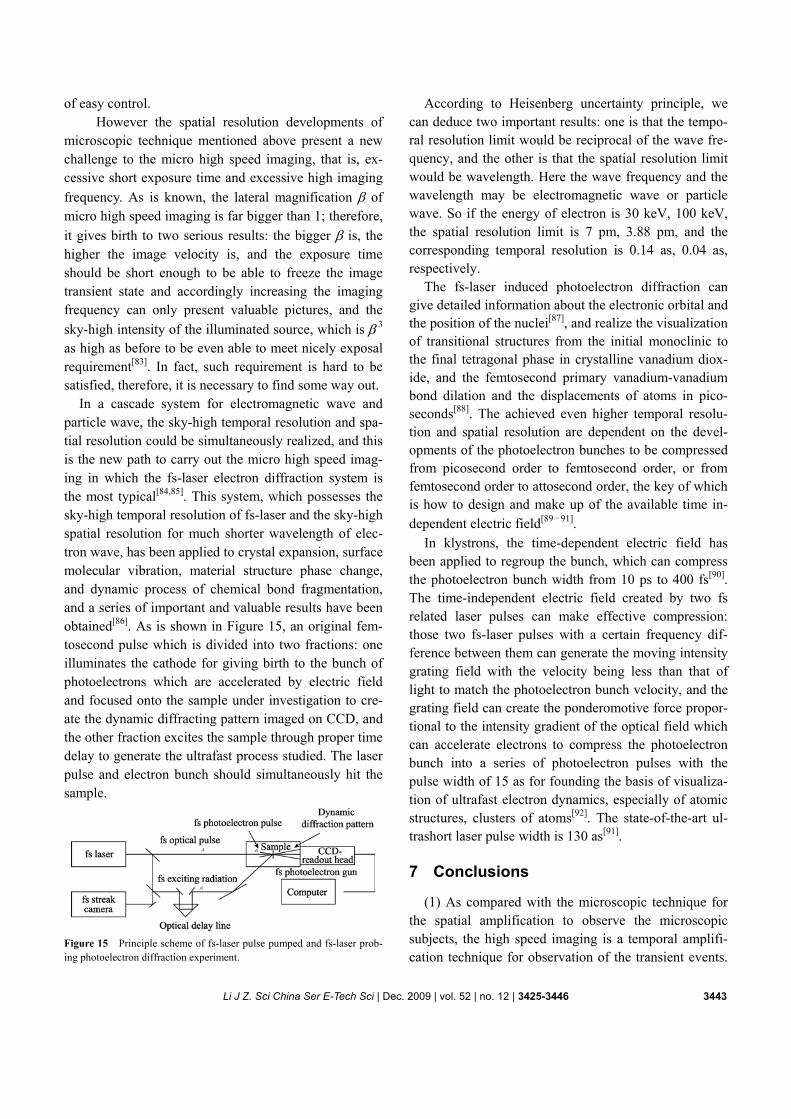
Li J Z. Sci China Ser E-Tech Sci | Dec. 2009 | vol. 52 | no. 12 | 3425-3446 3443
of easy control. However the spatial resolution developments of
microscopic technique mentioned above present a new challenge to the micro high speed imaging, that is, ex-cessive short exposure time and excessive high imaging frequency. As is known, the lateral magnification β of micro high speed imaging is far bigger than 1; therefore, it gives birth to two serious results: the bigger β is, the higher the image velocity is, and the exposure time should be short enough to be able to freeze the image transient state and accordingly increasing the imaging frequency can only present valuable pictures, and the sky-high intensity of the illuminated source, which is β 3 as high as before to be even able to meet nicely exposal requirement[83]. In fact, such requirement is hard to be satisfied, therefore, it is necessary to find some way out.
In a cascade system for electromagnetic wave and particle wave, the sky-high temporal resolution and spa-tial resolution could be simultaneously realized, and this is the new path to carry out the micro high speed imag-ing in which the fs-laser electron diffraction system is the most typical[84,85]. This system, which possesses the sky-high temporal resolution of fs-laser and the sky-high spatial resolution for much shorter wavelength of elec-tron wave, has been applied to crystal expansion, surface molecular vibration, material structure phase change, and dynamic process of chemical bond fragmentation, and a series of important and valuable results have been obtained[86]. As is shown in Figure 15, an original fem-tosecond pulse which is divided into two fractions: one illuminates the cathode for giving birth to the bunch of photoelectrons which are accelerated by electric field and focused onto the sample under investigation to cre-ate the dynamic diffracting pattern imaged on CCD, and the other fraction excites the sample through proper time delay to generate the ultrafast process studied. The laser pulse and electron bunch should simultaneously hit the sample.
Figure 15 Principle scheme of fs-laser pulse pumped and fs-laser prob-ing photoelectron diffraction experiment.
According to Heisenberg uncertainty principle, we can deduce two important results: one is that the tempo-ral resolution limit would be reciprocal of the wave fre-quency, and the other is that the spatial resolution limit would be wavelength. Here the wave frequency and the wavelength may be electromagnetic wave or particle wave. So if the energy of electron is 30 keV, 100 keV, the spatial resolution limit is 7 pm, 3.88 pm, and the corresponding temporal resolution is 0.14 as, 0.04 as, respectively.
The fs-laser induced photoelectron diffraction can give detailed information about the electronic orbital and the position of the nuclei[87], and realize the visualization of transitional structures from the initial monoclinic to the final tetragonal phase in crystalline vanadium diox-ide, and the femtosecond primary vanadium-vanadium bond dilation and the displacements of atoms in pico-seconds[88]. The achieved even higher temporal resolu-tion and spatial resolution are dependent on the devel-opments of the photoelectron bunches to be compressed from picosecond order to femtosecond order, or from femtosecond order to attosecond order, the key of which is how to design and make up of the available time in-dependent electric field[89―91].
In klystrons, the time-dependent electric field has been applied to regroup the bunch, which can compress the photoelectron bunch width from 10 ps to 400 fs[90]. The time-independent electric field created by two fs related laser pulses can make effective compression: those two fs-laser pulses with a certain frequency dif-ference between them can generate the moving intensity grating field with the velocity being less than that of light to match the photoelectron bunch velocity, and the grating field can create the ponderomotive force propor-tional to the intensity gradient of the optical field which can accelerate electrons to compress the photoelectron bunch into a series of photoelectron pulses with the pulse width of 15 as for founding the basis of visualiza-tion of ultrafast electron dynamics, especially of atomic structures, clusters of atoms[92]. The state-of-the-art ul-trashort laser pulse width is 130 as[91].
7 Conclusions
(1) As compared with the microscopic technique for the spatial amplification to observe the microscopic subjects, the high speed imaging is a temporal amplifi-cation technique for observation of the transient events.
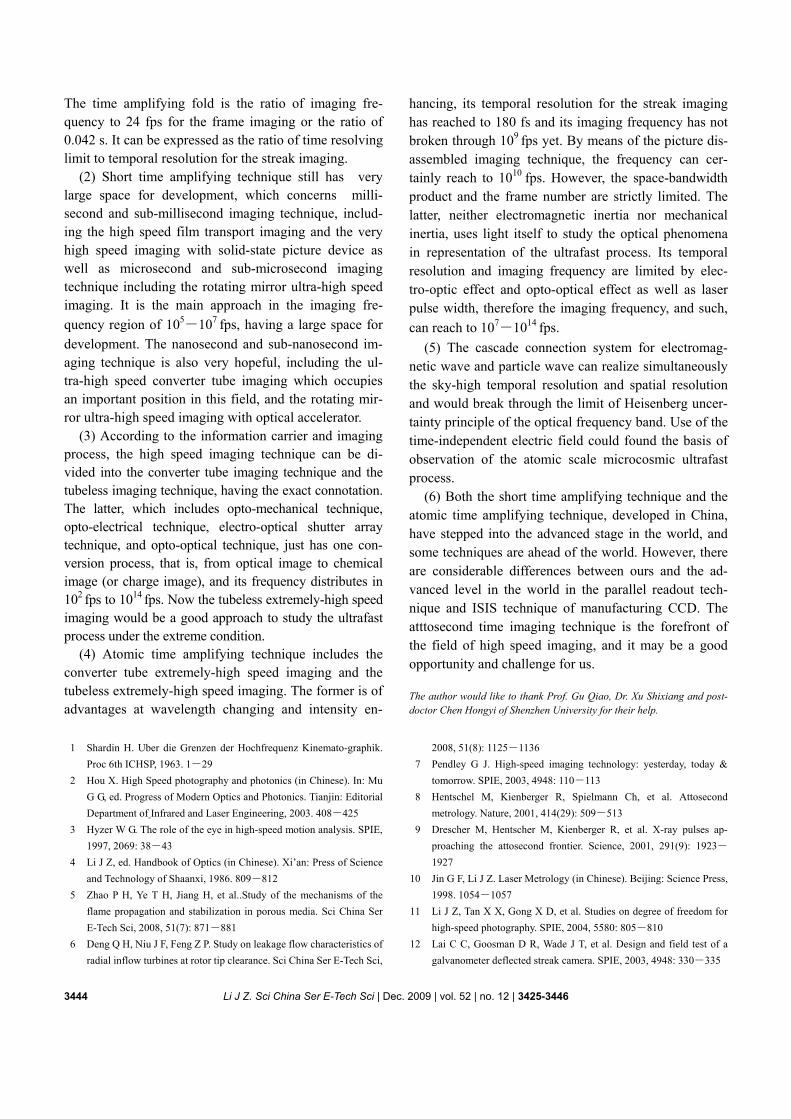
3444 Li J Z. Sci China Ser E-Tech Sci | Dec. 2009 | vol. 52 | no. 12 | 3425-3446
The time amplifying fold is the ratio of imaging fre-quency to 24 fps for the frame imaging or the ratio of 0.042 s. It can be expressed as the ratio of time resolving limit to temporal resolution for the streak imaging.
(2) Short time amplifying technique still has very large space for development, which concerns milli-second and sub-millisecond imaging technique, includ-ing the high speed film transport imaging and the very high speed imaging with solid-state picture device as well as microsecond and sub-microsecond imaging technique including the rotating mirror ultra-high speed imaging. It is the main approach in the imaging fre-quency region of 105―107 fps, having a large space for development. The nanosecond and sub-nanosecond im-aging technique is also very hopeful, including the ul-tra-high speed converter tube imaging which occupies an important position in this field, and the rotating mir-ror ultra-high speed imaging with optical accelerator.
(3) According to the information carrier and imaging process, the high speed imaging technique can be di-vided into the converter tube imaging technique and the tubeless imaging technique, having the exact connotation. The latter, which includes opto-mechanical technique, opto-electrical technique, electro-optical shutter array technique, and opto-optical technique, just has one con-version process, that is, from optical image to chemical image (or charge image), and its frequency distributes in 102 fps to 1014 fps. Now the tubeless extremely-high speed imaging would be a good approach to study the ultrafast process under the extreme condition.
(4) Atomic time amplifying technique includes the converter tube extremely-high speed imaging and the tubeless extremely-high speed imaging. The former is of advantages at wavelength changing and intensity en-
hancing, its temporal resolution for the streak imaging has reached to 180 fs and its imaging frequency has not broken through 109 fps yet. By means of the picture dis-assembled imaging technique, the frequency can cer-tainly reach to 1010 fps. However, the space-bandwidth product and the frame number are strictly limited. The latter, neither electromagnetic inertia nor mechanical inertia, uses light itself to study the optical phenomena in representation of the ultrafast process. Its temporal resolution and imaging frequency are limited by elec-tro-optic effect and opto-optical effect as well as laser pulse width, therefore the imaging frequency, and such, can reach to 107―1014 fps.
(5) The cascade connection system for electromag-netic wave and particle wave can realize simultaneously the sky-high temporal resolution and spatial resolution and would break through the limit of Heisenberg uncer-tainty principle of the optical frequency band. Use of the time-independent electric field could found the basis of observation of the atomic scale microcosmic ultrafast process.
(6) Both the short time amplifying technique and the atomic time amplifying technique, developed in China, have stepped into the advanced stage in the world, and some techniques are ahead of the world. However, there are considerable differences between ours and the ad-vanced level in the world in the parallel readout tech-nique and ISIS technique of manufacturing CCD. The atttosecond time imaging technique is the forefront of the field of high speed imaging, and it may be a good opportunity and challenge for us.
The author would like to thank Prof. Gu Qiao, Dr. Xu Shixiang and post-doctor Chen Hongyi of Shenzhen University for their help.
1 Shardin H. Uber die Grenzen der Hochfrequenz Kinemato-graphik.
Proc 6th ICHSP, 1963. 1―29 2 Hou X. High Speed photography and photonics (in Chinese). In: Mu
G G, ed. Progress of Modern Optics and Photonics. Tianjin: Editorial Department of Infrared and Laser Engineering, 2003. 408―425
3 Hyzer W G. The role of the eye in high-speed motion analysis. SPIE, 1997, 2069: 38―43
4 Li J Z, ed. Handbook of Optics (in Chinese). Xi’an: Press of Science and Technology of Shaanxi, 1986. 809―812
5 Zhao P H, Ye T H, Jiang H, et al..Study of the mechanisms of the flame propagation and stabilization in porous media. Sci China Ser E-Tech Sci, 2008, 51(7): 871―881
6 Deng Q H, Niu J F, Feng Z P. Study on leakage flow characteristics of radial inflow turbines at rotor tip clearance. Sci China Ser E-Tech Sci,
2008, 51(8): 1125―1136 7 Pendley G J. High-speed imaging technology: yesterday, today &
tomorrow. SPIE, 2003, 4948: 110―113 8 Hentschel M, Kienberger R, Spielmann Ch, et al. Attosecond
metrology. Nature, 2001, 414(29): 509―513 9 Drescher M, Hentscher M, Kienberger R, et al. X-ray pulses ap-
proaching the attosecond frontier. Science, 2001, 291(9): 1923―
1927 10 Jin G F, Li J Z. Laser Metrology (in Chinese). Beijing: Science Press,
1998. 1054―1057 11 Li J Z, Tan X X, Gong X D, et al. Studies on degree of freedom for
high-speed photography. SPIE, 2004, 5580: 805―810 12 Lai C C, Goosman D R, Wade J T, et al. Design and field test of a
galvanometer deflected streak camera. SPIE, 2003, 4948: 330―335
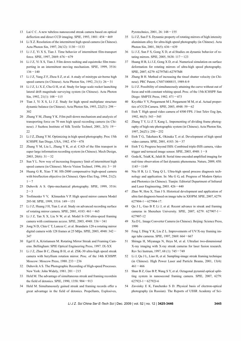
Li J Z. Sci China Ser E-Tech Sci | Dec. 2009 | vol. 52 | no. 12 | 3425-3446 3445
13 Lai C C. A new tubeless nanosecond streak camera based on optical deflection and direct CCD imaging. SPIE, 1993, 1801: 454―469
14 Li X Z. Resolution of the intermittent high speed camera (in Chinese). Acta Photon Sin, 1997, 26(12): 1130―1133
15 Li J Z, Yi X S, Tian J. Time behavior of intermittent film-transport force. SPIE, 1997, 2869: 676―679
16 Li J Z, Yi X S, Tian J. Film down rushing and equistroke film trans-porting in an intermittent moving mechanism. SPIE, 1999, 3516: 136―140
17 Li J Z, Yang Z F, Zhou S Z, et al. A study of minitype air-borne high speed camera (in Chinese). Acta Photon Sin, 1992, 21(1): 26―31
18 Li J Z, Li X Z, Cha G H, et al. Study for large scale rocket launching lateral drift magnitude surveying system (in Chinese). Acta Photon Sin, 1992, 21(1): 108―115
19 Tian J, Yi X S, Li J Z. Study for high speed multiplane structure dynamic balance (in Chinese). Acta Photon Sin, 1993, 22(Z1): 298―
302 20 Zhang Y M, Zhang Y K. Film pull-down mechanism and analysis of
transporting force on 70 mm high speed recording camera (in Chi-nese). J Suzhou Institute of Silk Textile Technol, 2001, 2(5): 19―
22 21 Li J Z, Zhang Y M. Optimizing in high speed photography. Proc 15th
ICHSPP, San Diego, USA, 1982. 474―478 22 Zhang Y M, Liu L, Zhang Y K, et al. CAD of the film transport in
super large information recording system (in Chinese). Mech Design, 2003, 20(6): 31―32
23 Sun Y L. New way of increasing frequency limit of intermittent high speed camera (in Chinese). Movie Vision Technol, 1996, (6): 3―10
24 Huang G R, Xiao T M. HS-2000 compensative high-speed camera with bireflection objective (in Chinese). Opto-Elec Eng, 1994, 21(2): 1―7
25 Dubovik A S. Opto-mechanical photography. SPIE, 1999, 3516: 2―3
26 Trofimenko V V, Klimashin V P. High speed mirror camera Model 203-M. SPIE, 1999, 3516: 149―151
27 Li J Z, Huang J H, Tian J, et al. Study on advanced recording surface of rotating mirror camera. SPIE, 2001, 4183: 461―465
28 Li J Z, Tan X X, Liu N W, et al. Model S-150 ultra-speed framing camera with continuous access. SPIE, 2003, 4948: 336―341
29 Jong N D, Chin C T, Lancee C, et al. Brandaris 128-a rotating mirror digital camera with 128 frames at 25 Mfps. SPIE, 2003, 4948: 342―
347 30 Egel E A, Kristiansen M. Rotating Mirror Streak and Framing Cam-
eras. Bellingham: SPIE Optical Engineering Press, 1997. IX-XX 31 Li J Z, Zhao B C, Zhang B H, et al. ZSK-30 ultra-high speed streak
camera with beryllium rotation mirror. Proc. of the 14th ICHSPP. Moscow: Moscow Press, 1980. 233―236
32 Dubovik A S. The Photographic Recording of High-speed Processes. New York: John Widely, 1981. 201―215
33 Held M. The advantage of simultaneous streak and framing recordsin the field of detonics. SPIE, 1990, 1358: 904―913
34 Held M. Simultaneously gained streak and framing records offer a great advantage in the field of detonics. Propellants, Explosives,
Pyrotechnics, 2001, 26: 148―155 35 Li J Z, Sun F S. Dynamic property of rotating mirrors of high intensity
aluminium alloy for ultra-high speed photography (in Chinese). Acta Photon Sin, 2001, 30(5): 636―639
36 Li J Z, Sun F S, Gong X D, et al.Studies on dynamic behavior of ro-tating mirrors. SPIE, 2005, 5638: 117―123
37 Huang H B, Li J Z, Gong X D, et al. Numerical simulation on surface deformation for rotating mirrors of ultra-high speed photography. SPIE, 2007, 6279: 62797M1-62797M8
38 Zhang B H. Method of increasing the tinsel shutter velocity (in Chi-nese). PRC Patent, CN871008815, 1989-8-9
39 Li J Z. Possibility of simultaneously attaining the curve without out of focus and with constant whiting speed. Proc. of the 15th ICHSPP. San Diego: SMPTE Press, 1982. 471―473
40 Kryzhko V V, Pergarment M I, Pergarnent M M, et al. Actual proper-ties of CCD-Camera. SPIE, 2003, 4948: 59―62
41 Etoh T. High speed video camera of 4500 FPS. J Inst Telev Eng Jpn, 1992, 46(5): 543―545
42 Zhang T Y, Li Z T, Kang L. Impementing of dividing frame photog-raphy of high rate photographic system (in Chinese). Acta Photon Sin, 1997, 26(Z1): 250―252
43 Etoh T G., Takehara K, Okinaka T, et al. Development of high speed video camera. SPIE, 2001, 4183: 36―37
44 Etoh T G. Progress beyond ISIS: Combined triple-ISIS camera, video trigger and terraced image sensor. SPIE, 2003, 4948: 1―8
45 Goda K, TsiaK K, Jalali B. Serial time-encoded amplified imaging for real-time observation of fast dynamic phenomena. Nature, 2009, 458: 1145―1149
46 Niu H B, Li J, Yang Q L. Ultra-high speed process diagnosis tech-nology and application. In: Mu G G, ed. Progress of Modern Optics and Photonics (in Chinese). Tianjin: Editorial Department of Infrared and Laser Engineering, 2003. 426―440
47 Zhao W, Hou X, Tian J S. Historical development and application of ultra fast diagnosis based on image tube in XIOPM. SPIE, 2007, 6279: 627904-1―627904-17.
48 Qu J L, Guo B P, Li J, et al. Recent advance in streak and framing cameras in Shenzhen University. SPIE, 2007, 6279: 627907-1―
627907-12 49 Xu D L. Image Converter Camera (in Chinese). Beijing: Science Press,
1990 50 Feng J, Ding Y K, Liu Z L. Improvements of UV/X-ray framing im-
age tube cameras. SPIE, 1997, 2869: 664―667 51 Shiraga H, Miyanaga N, Heya M, et al. Ultrafast two-dimensional
X-ray imaging with X-ray streak cameras for laser fusion research. Rev Sci Instrum, 1997, 68 (1): 745―749
52 Li J, Qu J L, Liao H, et al. Sampling-image streak framing technique (in Chinese). High Power Laser and Particle Beams, 2001, 13(4): 461―466
53 Shan B Z, Guo B P, Wang S Y, et al. Octagonal pyramid optical split-ting system in nanosecond framing camera. SPIE, 2007, 6279: 62792J-1―62792J-6
54 Zavoisky Е К, Fanchenko S D. Physical basis of electron-optical photography (in Russian). The Reports of USSR Academy of Sci-
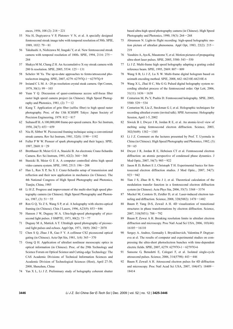
3446 Li J Z. Sci China Ser E-Tech Sci | Dec. 2009 | vol. 52 | no. 12 | 3425-3446
ences, 1956, 108 (2): 218―221 55 Niu H, Degtyareva V P, Platonov V N, et al. A specially designed
femtosecond streak image tube with temporal resolution of 50fs. SPIE, 1989, 1032: 79―81
56 Takahashi A, Nishizawa M, Inagaki Y, et al. New femtosecond streak camera with temporal resolution of 180fs. SPIE, 1994, 2116: 275―
284 57 Shakya M M, Chang Z H. An Accumulative X-ray streak camera with
280 fs resolution. SPIE, 2005, 5534: 125―131 58 Schelev M Ya. The up-to-date approaches to femto/attosecond pho-
toelectron imaging. SPIE, 2007, 6279: 62797Q-1―62797Q-9 59 Ireiand C L M. A ~20 ps resolution crystal steak camera. Opt Comm,
1979, 30(1): 99―103 60 Yuan Y Q. Discussion of quasi-continuous access self-focus fiber
raster high speed camera project (in Chinese). High Speed Photog-raphy and Photonics, 1981, (2): 7―12
61 Kung T. Application of grin fiber (selfoc fiber) to high speed raster photography. Proc. of the 13th ICHSPP. Tokyo: Japan Society of Precision Engineering, 1979. 812―817
62 Sultanoff H. A 100,000,000 frame-per-speed camera. Rev Sci Instrum, 1950, 24(7): 653―659
63 Niu H, Sibbet W. Picosecond framing technique using a conventional streak camera. Rev Sci Instrum, 1981, 52(8): 1190―1192
64 Fuller P W W. Pioneer of spark photography and their legacy. SPIE, 1997, 2869: 8―29
65 Bretthauer B, Meier G E A, Stasicki B. An electronic Cranz-Schardin Camera. Rev Sci Instrum, 1991, 62(2): 364―368
66 Stasicki B, Meier G E A. A computer controlled ulrtra high speed video camera system. SPIE, 1995, 2513: 196―208
67 Han L, Ren X P, Su X J. Cranz-Schardin setup of transmission and reflection and their new application in mechanics (in Chinese). The 4th National Congress of High Speed Photography and Photonics, Tianjin, China, 1985
68 Li H Z. Progress and improvement of the multi-shot high speed pho-tography camera (in Chinese). High Speed Photography and Photon-ics, 1987, (3): 51―55
69 Ren G Q, Ye Z S, Wang S P, et al. A holography with electro-optical framing (in Chinese). Chin J Lasers, 1996, A23(9): 853―846
70 Hanson J W, Duguay M A. Ultra-high-speed photography of pico-second light pulses. J SMPTE, 1971, 80(2): 73―77
71 Duguay M A, Mattick A T. Ultrahigh speed photography of picosec- ond light pulses and echoes. Appl Opt, 1971, 10(9): 2062―2070
72 Chen S Q, Zhao J R, Gao F Y. A collinear CS2 picosecond optical gating (in Chinese). Acta Opt Sin, 1981, 1(4): 365―370
73 Gong Q H. Application of ultrafast nonlinear mesoscopic optics in optical information (in Chinese). Proc. of the 29th Technology and Science Forum on Optical Science and Cutting-edge Technology: The CAS Academic Divisions of Technical Information Sciences and Academic Division of Technological Sciences (Host), April 27-30, 2008, Shenzhen, China
74 Yan X L, Li J Z. Preliminary study of holography coherent shutter
based ultra-high speed photography camera (in Chinese). High Speed Photography and Photonics, 1990, 19(3): 264―268
75 Abramson N. Light-in flight recording: high-speed holographic mo-tion picture of ultrafast phenomena. Appl Opt, 1983, 22(2): 215―
219 76 Yasuhiro A, Aya K, Masatomo Y, et al. Motion pictures of propagating
ultra-short laser pulses. SPIE, 2005, 5580: 543―550 77 Li J Z. Multi-frame high speed holography adapting a grating coded
reference beam. SPIE, 1995, 2869: 807―809 78 Wang S B, Li J Z, Lu X W. Multi-frame digital hologram based on
azimuth encoding method. SPIE, 2008, 662: 66210E-66210E-6 79 Wang X L, Zhai H C, Mu G G. Pulsed digital holography system re-
cording ultrafast process of the femtosecond order. Opt Lett, 2006, 31(11): 1636―1638
80 Centurion M, Pu Y, Psaltis D. Femtosecond holography. SPIE, 2005, 5580: 529―534
81 Centurion M, Liu Z, Steckman G J, et al. Holographic techniques for recording ultrafast events (invited talk). SPIE Aerosense: Holography Session, April 1-5, 2002
82 Siwick B J, Dwyer J R, Jordan R E, et al. An atomic-level view of melting using femtosecond electron diffraction. Science, 2003, 302(5649): 1382―1385
83 Li J Z. Comment on the lectures presented by Prof. T. Uyemula in China (in Chinese). High Speed Photography and Photonics, 1982, (3): 59―65
84 Dwyer J R, Jordan R E, Hebeisen CT et al. Femtosecond electron diffraction: an atomic perspective of condensed phase dynamics. J Mod Optic, 2007, 54(7): 905―922
85 Jason R D, Robert E J, Christoph T H. Experimental basics for fem-tosecond electron diffraction studies. J Mod Optic., 2007, 54(7): 923―942
86 Tian J S, Zhao B S, Wu J J, et al. Theoretical calculation of the modulation transfer function in a femtosecond electron diffraction system (in Chinese). Acta Phys Sin, 2006, 55(7): 3368―3374
87 Meckel M, Comtois D, Zeidler D, et al. Laser-induced electron tun-neling and diffraction. Science, 2008, 320(5882): 1478―1482
88 Baum P, Yang D-S, Zewail A H. 4D visualization of transitional structures in phase transformations by electron diffraction. Science, 2007, 318(5851): 788―792
89 Baum P, Zewai A H. Breaking resolution limits in ultrafast electron diffraction and microscopy. Proc Natl Acad Sci USA, 2006, 103(44): 16105―16110
90 Sergey A. Andree, Gennadiy I. Bryuklinevich, Valentina P. Degtyar- eva at el. The results of computer and experimental studies on com- pressing the ultra-short photoelectron bunches with time-dependent electric fields. SPIE, 2007, 6279: 62797O-1―62797O-6
91 Sansone G, Benedetti E, Calegari F, et al. Isolated single-cycle attosecond pulses. Science, 2006, 314(5798): 443―446
92 Baum P, Zewail A H. Attosecond electron pulses for 4D diffraction and microscopy. Proc Natl Acad Sci USA, 2007, 104(47): 18409―
18414