Embed Size (px)
Citation preview
Page 1
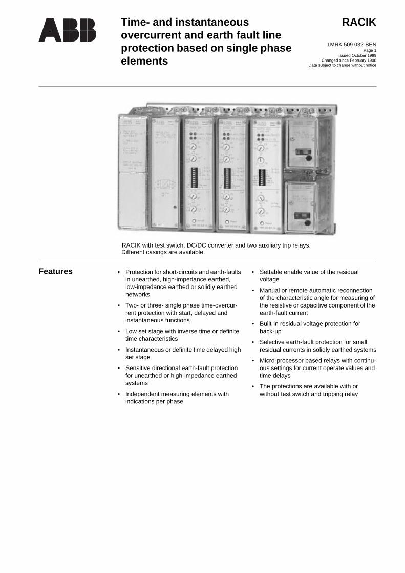
RACIK with test switch, DC/DC converter and two auxiliary trip relays.Different casings are available.
Time- and instantaneous overcurrent and earth fault line protection based on single phase elements
RACIK
1MRK 509 032-BEN
Issued October 1999Changed since February 1998
Data subject to change without notice
Features • Protection for short-circuits and earth-faults in unearthed, high-impedance earthed, low-impedance earthed or solidly earthed networks
• Two- or three- single phase time-overcur-rent protection with start, delayed and instantaneous functions
• Low set stage with inverse time or definite time characteristics
• Instantaneous or definite time delayed high set stage
• Sensitive directional earth-fault protection for unearthed or high-impedance earthed systems
• Independent measuring elements withindications per phase
• Settable enable value of the residual voltage
• Manual or remote automatic reconnection of the characteristic angle for measuring of the resistive or capacitive component of the earth-fault current
• Built-in residual voltage protection forback-up
• Selective earth-fault protection for small residual currents in solidly earthed systems
• Micro-processor based relays with continu-ous settings for current operate values and time delays
• The protections are available with or without test switch and tripping relay

Time- and instantaneous overcurrent and earth fault line protection based on single phase elements
RACIK1MRK 509 032-BEN
Page 2
-
d
c-a
t -
c-
e le
c
l
e.
r-
s
Application The RACIK is available in several versions and is used to protect feeders in networks. It can also be used as back-up protections in transmission network.
Overcurrent protectionTwo- or three-phase time-overcurrent relay is used as phase short-circuit protection in radial networks. The overcurrent protection func-tion of RACIK is provided by the single phase time-overcurrent relay elements RXIDK 2H.
In the three-phase protection, both phase cur-rents are always measured when a two-phase fault occurs. The relay operates even if one of the measuring circuits is faulty. Three phase elements are therefore more dependable than two phase elements. Compared to a summa-tion type of three-phase measurement protec-tion, that has a common measuring circuit, considerably greater reliability is achieved.
As there always will be fault current in at least one of the phases during short-circuit, it often is quite adequate to use two-phase pro-tection for feeders.
RXIDK 2H has a low set stage with start and trip functions and a high set stage function. Several different time characteristics are available to achieve selective fault clearance. The high set stage can be set instantaneous or definitive-time delayed. The relay has also a fully isolated binary input. It can be pro-grammed to enable or block the relay. As an alternative the binary input can raise the oper-ate value of the low set stage with 40%. This function is called ”cold load” and facilitates restoration of distribution systems after out-age.
In radially supplied networks, the start func-tion can be used for blocking a blockable bus-bar protection. It can also be used for starting recorders, autoreclosing or signalling.
In meshed systems inverse time overcurrent protections which all have the same setting can be used as back-up protections.
In some applications it is necessary to use directional overcurrent relays. In these cases the protection RAPDK is recommended, see 1MRK 509 007-BEN.
Earth-fault protectionThe earthing methods will influence the earth-fault current and therefore also the choice of the earth-fault protection. The sys-tem earthing can be either unearthed, high-impedance earthed, low-impedance earthedor solidly earthed.
Earth-fault protection in unearthed or high-impedance earthed systemsIn unearthed or high-impedance earthed systems where the capacitive current from the protected line is large compared to the wanteoperate value, directional residual current protections can be used for earth-fault protetion. The relay uses the residual voltage as polarizing quantity. The earth-fault protec-tions contain RXPDK 22H as measuring relay with independent time delay. The relayhas a characteristic angle α = 0° or α = -90°. The angle is set either by a switch on the fronside of the relay or by a binary input. Switching between α = 0° or α = -90° can thus be made externally via remote control or by means of a auxiliary contact in the disconnetor of the neutral point earthing equipment. The relay has a high sensitivity and a settingrange down to 3,7 mA.
In unearthed systems, the relay measures thcapacitive current and the characteristic angset to α = -90°. In high-impedance earthed system with a neutral point resistor with or without a reactor in parallel the characteristiangle shall be set to α = 0° and the relay mea-sures the resistive component of the earth-fault current.
The RXPDK 22H also measures the residuavoltage. This function is used for enabling directional operation. It is also used as a back-up protection. By selecting different time delay based on the failure rate for the different feeders and the priority of critical loads it is possible to reduce the conse-quences in case of a back-up fault clearanc
Earth-fault protection in solidly earthed HV & EHV systemIn solidly earthed systems the earth-fault curents can be of the same order of magnitudeas the short-circuit currents. By measuring the residual current the non-directional RXIDK 2H can be used as simple alternativeof earth-fault protections for radial feeders and as back-up protections. For pure RXIDK 2H 1-4 single phase element assemblieplease see 1MRK 509 002-BEN.

Time- and instantaneous overcurrent and earth fault line protection based on single phase elements
RACIK1MRK 509 032-BEN
Page 3
Earth-faults with high fault resistance can be detected by measuring the residual current. This type of protection provides maximum sensitivity to earth-faults with additional resistance. It is often required to clear earth-fault with residual currents of magnitudes which are as low as 50-100 A.
A sensitive non-directional inverse time residual overcurrent protection is a suitable solution to get a selective protection in most cases. A logarithmic characteristic is gener-ally the most suitable for the purpose of selectivity, since the time difference is con-stant for a given ratio between the currents. The combined definite and logarithmic inverse time characteristic available in the RXIDG 21H relay is designed to achieve
optimum selectivity. The same type of inverse time-current characteristic should be used for all earth-fault overcurrent protec-tions in the network. The selectivity is ensured when the largest infeed is less than 80% of the current on the faulty line. The set-tings for all objects shall be the same.
When energizing a solidly earthed power transformer, the residual inrush current can cause unwanted operation of the earth-fault overcurrent protection. RXIDG 21H is pro-vided with a fully isolated binary input, which is programmed to either enable or block the relay when activated. A second har-monic restraint relay type RAISB can be con-nected to prevent unwanted operation at transformer energizing.
Design The protection RACIK is designed in anumber of variants for two- or three-phase overcurrent protections and/or earth-fault protection. It is built up based upon time overcurrent relay RXIDK 2H, RXIDG 21H and directional time overcurrent relay RXPDK 22H. Each protection is available with or without test switch RTXP 18, DC-DC converter RXTUG 22H or tripping relay RXME 18. With RXTUG 22H all require-ments concerning disturbance emission and immunity with this protection assembly will be met.
All protections are built up by modules in the COMBIFLEX modular system mounted on apparatus bars. The connections to the protec-tions are done by COMBIFLEX socket equipped leads. A short circuiting connector RTXK is mounted on the rear of the terminal base and will automatically short-circuit the current input when the relay is removed from its terminal base.
RXIDK 2H measuring relayThe time-overcurrent relay RXIDK 2H con-sists mainly of an input transformer for cur-rent adoption and isolation, filter circuits, digital-analog converter, microprocessor, HMI consisting of a programming switch and potentiometers for setting and LEDs for start, trip and in service indications, and three out-put relays, each with a change-over contact, for the start and trip functions of the low set stage and for the trip function of the high set
stage respectively. The relay has also a binary input by which the operation can be enabled or blocked or the operate value of the low set stage increased by 40%.
RXIDG 21H measuring relayThe time-overcurrent relay RXIDG 21H con-sists mainly of an input transformer for cur-rent adoption and isolation, filter circuits, digital-analog converter, microprocessor, HMI consisting of a programming switch and potentiometers for setting and LEDs for start, trip and in service indications, and three out-put relays, each with a change-over contact, for the start and trip functions. The relay has also a binary input by which the operation can be enabled or blocked.
RXPDK 22H measuring relayThe directional time-overcurrent relay RXPDK 22H consists mainly of two input transformers for current and voltage adoption and isolation, filter circuits, digital-analog converter, microprocessor, HMI consisting of a programming switch and potentiometers for setting and LEDs for start, trip and in service indications, and three output relays, each with a change over contact, for the start and trip functions of the directional stage and for trip function of the over- or under-voltage func-tion. The relay has also two binary inputs for remote resetting of LED indications and for changing the characteristic angle from 0° to -90° or vice versa.

Time- and instantaneous overcurrent and earth fault line protection based on single phase elements
RACIK1MRK 509 032-BEN
Page 4
Technical data Time-overcurrent relay RXIDK 2HTable 1: Current input
Rated current Ir 1 A or 5 A
Scale constant Is (0,1 0,2 0,4 1,0) x Ir
Setting ranges1 A Variant I >
I>>5 A Variant I >
I>>
0,075-3,25 A0,1-40 A0,375-16,25 A0,5-200 A
Effective current range (0,75-65) x Is
Rated frequency frFrequency characteristics
50-60 HzFilter options: 50-60 Hz flat, (standard variant) see Fig. 1
Power consumption 1 A variant I = Is = 0,1 A
I = Is = 1 A5 A variant I = Is = 0,5 A
I = Is = 5 A
0,5 mVA50 mVA1 mVA100 mVA
Overload capacity for 1 A variant continuously5 A variant continuously1 A variant during 1 s5 A variant during 1 s
6 A20 A100 A350 A

Time- and instantaneous overcurrent and earth fault line protection based on single phase elements
RACIK1MRK 509 032-BEN
Page 5
Table 2: Current functions, standard variant
Current function Low set stage I> High set stage I>>
Setting range (0,75-3,25) x Is (1-40) x Is and ∞
Operate time, typicalI = 0 = > 1,3 x I > I = 0 = > 3 x I > I = 0 = > 10 x I >
35 ms25 ms20 ms
Reset time, typicalI = 1,3 = > 0 x I > I = 3 = > 0 x I > I = 10 = > 0 x I >
25 ms35 ms45 ms
Consistency of operate value < 0,5%
Reset ratio (typical)Consistency
95%< 1,5%
“Cold load” activated Operate valueincreases 40%
N.A
Transient over-reach L/R = 10, 50 and 100 ms < 5%
Overshoot time < 20 ms
Recovery time at I = 3 x I> < 40 ms
Frequency dependence within frequency range 47,5 - 63,0 Hz < 2,5%
Operate value at 150 Hz App. 1,5 x set op. value
Influence of harmonics100 / 120 Hz, 10%150 / 180 Hz, 20%250 / 300 Hz, 20%
< 3%< 6%< 4%
Temperature dependence within range -5°C to +55°C < 2%
Table 3: Time function
Time function Low set stage I> High set stage I>>
Time delay Inverse and definite time(Normal, Very, Extremely, Long time and RI inverse time)
Definite time
Setting rangeDefinite timeInverse time
0,05-8,1 sk = 0,05-1,1
0,03-1,0 s–
AccuracyDefinite timeInverse time
Consistency
1% and ±10 msNI, VI, EI and LI 2 x op. value 12,5% and ±30 msNI, VI, EI and LI 5 x op. value 7,5% and ±30 msNI, VI, EI and LI 10 x op. value 5% and ±30 msNI, VI, EI and LI 20 x op. value 5% and ±30 msRI 1,0 x op. value 12,5% and ±30 ms
1,3 x op. value 12,5% and ±30 ms1,5 x op. value 5% and ±30 ms10 x op. value 5% and ±30 ms20 x op. value 5% and ±30 ms
< 0,5%
1% and ±10 ms
< 0,5%

Time- and instantaneous overcurrent and earth fault line protection based on single phase elements
RACIK1MRK 509 032-BEN
Page 6
Technical data(cont’d)
See also technical data common for RXIDK 2H, RXIDG 21H and RXPDK 22H
Fig. 1 Typical frequency characteristic for RXIDK 50-60 Hz, standard, valid for I ≤ 65 x Is(There is risk for contact chattering with frequency ≤ 30 Hz)
Table 4: Filter options, deviation from technical data for RXIDK 2H, standard variant
Filter options
50-60 Hz,sharp
150-180 Hz,sharp
40-2000 Hz, flat
Operate time (typical)I = 0 = > 1,3 x op. valueI = 0 = > 2 x op. valueI = 0 = > 10 x op. value
65 ms 55 ms35 ms
45 ms35 ms25 ms
35 ms25 ms20 ms
Reset time (typical)I = 1,3 = > 0 x op. valueI = 2 = > 0 x op. valueI = 10 = > 0 x op. value
40 ms 50 ms100 ms
30 ms35 ms55 ms
20 ms25 ms50 ms
Reset ratio (typical) 95%
Recovery time at I = 3 x op. value < 65 ms < 45 ms < 40 ms
Overshoot time < 35 ms < 25 ms < 20 ms
Transient over-reach L/R = 10, 50and 100 ms < 2% < 2% < 20%
Frequency dependence within frequency range ±5% < 12% < 20% –
Influence of harmonics50, 60 Hz, 100%100, 120 Hz, 100%150, 180 Hz, 100%250, 300 Hz, 100%
–< 2%< 2%< 2%
< 1%< 4%–< 2%
–––
1
2
10
5
3
4
9876
20 30 40 50 60 100 150180 250300 500 1000
Operate current / set operate current
Frequency
Operate current / set operate current
Time- and instantaneous overcurrent and earth fault line protection based on single phase elements
RACIK1MRK 509 032-BEN
Page 7
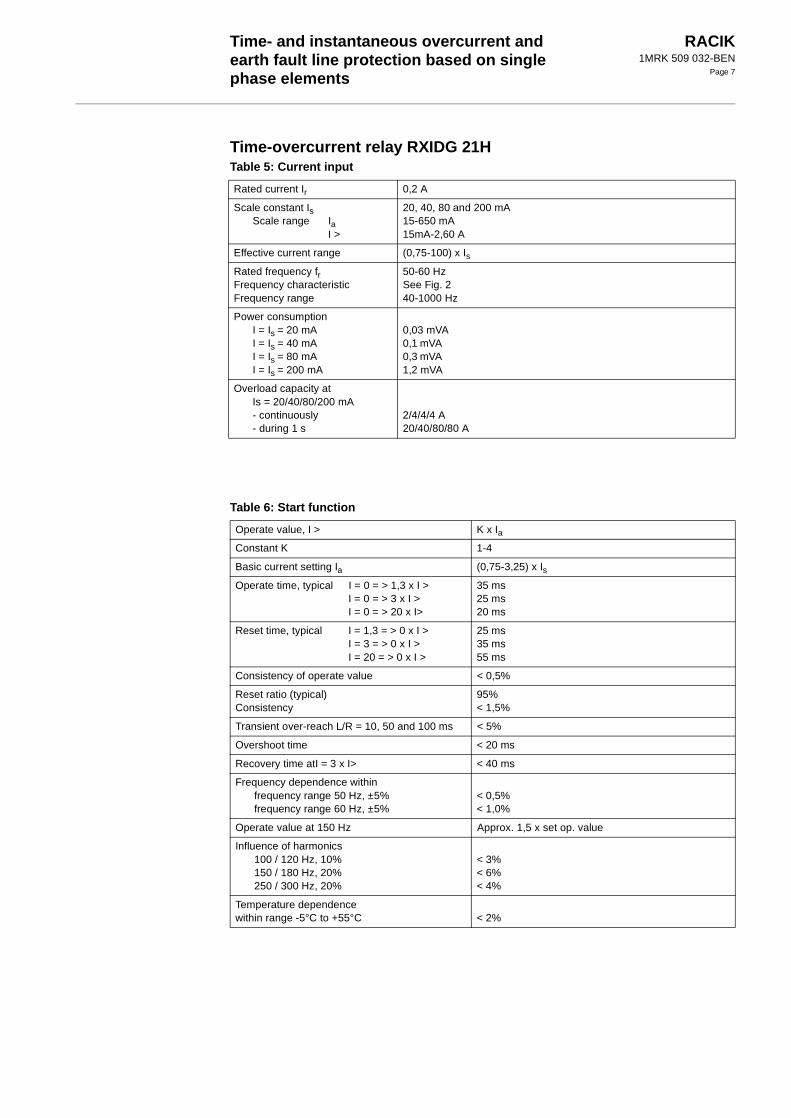
Time-overcurrent relay RXIDG 21HTable 5: Current input
Rated current Ir 0,2 A
Scale constant IsScale range Ia
I >
20, 40, 80 and 200 mA15-650 mA15mA-2,60 A
Effective current range (0,75-100) x Is
Rated frequency frFrequency characteristicFrequency range
50-60 HzSee Fig. 240-1000 Hz
Power consumption I = Is = 20 mAI = Is = 40 mAI = Is = 80 mAI = Is = 200 mA
0,03 mVA0,1 mVA0,3 mVA1,2 mVA
Overload capacity atIs = 20/40/80/200 mA- continuously- during 1 s
2/4/4/4 A20/40/80/80 A
Table 6: Start function
Operate value, I > K x Ia
Constant K 1-4
Basic current setting Ia (0,75-3,25) x Is
Operate time, typical I = 0 = > 1,3 x I > I = 0 = > 3 x I > I = 0 = > 20 x I>
35 ms25 ms20 ms
Reset time, typical I = 1,3 = > 0 x I > I = 3 = > 0 x I > I = 20 = > 0 x I >
25 ms35 ms55 ms
Consistency of operate value < 0,5%
Reset ratio (typical) Consistency
95%< 1,5%
Transient over-reach L/R = 10, 50 and 100 ms < 5%
Overshoot time < 20 ms
Recovery time atI = 3 x I> < 40 ms
Frequency dependence within frequency range 50 Hz, ±5%frequency range 60 Hz, ±5%
< 0,5%< 1,0%
Operate value at 150 Hz Approx. 1,5 x set op. value
Influence of harmonics100 / 120 Hz, 10%150 / 180 Hz, 20%250 / 300 Hz, 20%
< 3%< 6%< 4%
Temperature dependence within range -5°C to +55°C < 2%

Time- and instantaneous overcurrent and earth fault line protection based on single phase elements
RACIK1MRK 509 032-BEN
Page 8
Technical data (cont’d)Technical data (cont’d)
See also technical data common for RXIDK 2H, RXIDG 21H and RXPDK 22HTechnical data (cont’d)
Fig. 2 Typical frequency characteristic for RXIDG 50-60 Hz, valid for valid for I ≤ 100 x Is(There is risk for contact chattering with frequency ≤ 30 Hz)
Fig. 3 RXIDG logarthmic inverse characteristic with definite minimum time.
Table 7: Time function
Time delay Inverse time and definite time
Operate time for inverse time, InvAccuracy
Formula: t = 5,8 - 1,35 x ln I/Ia , at t > t0, see Fig. 3.Overall: ±100 ms
Setting range for definite time, Def.timeAccuracy
t0 = 1,0-2,0 sOverall: ±50 ms
1
2
10
5
3
4
9876
20 30 40 50 60 100 150180 250300 500 1000
Operate current / set operate current
Frequency
Operate current / set operate current
K = 1 K = 4
t0 = 2 s
t0 = 1 s1
2
3
4
5
6
7
1 2 3 5 7 10 20 30
t s
* Ia
I
40

Time- and instantaneous overcurrent and earth fault line protection based on single phase elements
RACIK1MRK 509 032-BEN
Page 9
Directional time-overcurrent relay RXPDK 22HTable 8: Voltage and current inputs
Rated voltage Ur 120 V
Rated current Ir 50 mA or 200 mA
Scale constant Is (0,1 0,2 0,4 and 1,0) x Ir
Setting ranges 50 mA Variant Iα >200 mA Variant Iα >
3,75 - 160 mA15 - 650 mA
Effective voltage range U 5-200 V
Effective current range (0,75-100) x Is
Rated frequency frOperating frequency range
50-60 Hz45-66 Hz
Power consumption for U = Ur
50 mA variant I = Is = 5 mAI = Is = 50 mA
200 mA variant I = Is = 20 mAI = Is = 200 mA
0,25 VA 0,05 mVA 1 mVA 0,1 mVA 1,5 mVA
Overload capacity voltage:- continuously- during 10 s
Overload capacity current:- continuously
50 mA variant Is = 5/10/20/50 mA200 mA variant Is = 20/40/80/200 mA
- during 1 s50 mA variant200 mA variant
250 V300 V
0,5/1/1/1 A2/4/4/4 A
5 A20 A

Time- and instantaneous overcurrent and earth fault line protection based on single phase elements
RACIK1MRK 509 032-BEN
Page 10
Table 9: Start function
Current function Stage I>
Setting range I > (0,75-3,25) x Is
Angle between U and I, ϕ Positive if I lags U
Settable characteristic angle α 0° or -90°
Operate conditions for I >, at selected program(U>, Iα>) and (U x I)(U>, Iα>) and (I indep U)(U<, I >) and (U enbl I)(U<, I >) and (I indep U)
I x cos (ϕ-α) ≥ set I > and U ≥ set U>I x cos (ϕ-α) ≥ set I > and U ≥ 5 VI ≥ set I > and U ≤ set U<I ≥ set I >
Logic for phase memory- low voltage phase memory- low voltage time out
Ignores angle changes when U < 5 VBlocks start function 1s after U has decreased to < 5 V
Binary input 1 “α-selection”Active signal on binary input 1,
Changes the characteristic angle α from 0 x ° to -90° or -90° to 0°
Accuracy for characteristic angle α1 to 8 x set op. value8 to 25 x set op. value25 to 100 x set op. value
Is = 0,1 x Ir< 5,5°< 2,5°< 1,5°
Is = 0,2 x Ir< 3,0°< 2,0°< 1,5°
Is = 0,4 x Ir< 2,0°< 2,5°< 2,0°
Is = 1,0 x Ir< 3,0°< 2,5°< 2,0°
Operate time at ϕ = α, typicalI = 0 = > 3 x I > I = 0 = > 10 x I >
Directional function85 ms80 ms
Non-directional function20 ms15 ms
Reset time at ϕ = α, typicalI = 3 = > 0 x I >I = 10 = > 0 x I >
Directional function30 ms40 ms
Non-directional function30 ms40 ms
Consistency of the op. value < 3% at ϕ = α < 2%
Reset ratio (typical) 90%
Transient over-reach L/R=10, 50 and 100 ms < 3% < 4%
Overshoot time < 50 ms < 20 ms
Recovery time at I = 3 x Iα> < 50 ms
Frequency dependence 45-65 Hz < ±5% < 3%
Influence of harmonics in:Voltage circuit
100 / 120 Hz, 30%150 / 180 Hz, 50%150 / 180 Hz, 180%250 / 300 Hz, 30%
Current circuit100 / 120 Hz, 5%150 / 180 Hz, 10%150 / 180 Hz, 20%150 / 180 Hz, 30%250 / 300 Hz, 20%
30%
Angle dependence
< 2°< 5°< 7°< 2°
< 2°< 6°< 9°< 12°< 7°< 11°
Current dependence
––––
< 3%< 3%< 7%< 7%< 4%< 6%

Time- and instantaneous overcurrent and earth fault line protection based on single phase elements
RACIK1MRK 509 032-BEN
Page 11
See also technical data common for RXIDK 2H, RXIDG 21H and RXPDK 22H
Table 10: Voltage function
Selected function U> or U< U> U<
Setting range U U = Us = (5-30) V U = 4 x Us = (5-120) V
Operate time Over-voltage (typical)U = 0 = > 1,1 x op. valueU = 0,9 = > 1,1 x op. value
Under-voltage (typical)U = 2,0 = > 0,9 x op. valueU = 1,1 = > 0,9 x op. value
60 ms45 ms
––
––
60 ms45 ms
Reset time Over-voltage (typical)U = 1,1 = > 0,9 x op. valueU = 1,1 = > 0 x op. value
Under-voltage (typical)U = 0,9 = > 1,1 x op. valueU = 0,9 = > 2,0 x op. value
60 ms35 ms
––
––
60 ms35 ms
Consistency of the op. value < 2%
Reset ratio, (typical) 90% 110%
Overshoot time < 40 ms
Recovery timeOver-voltage U= 0 = > 1,1 x op. valueUnder-voltage U= 2,0 = > 0,9 x op. value
< 55 ms–
–< 55 ms
Frequency dependence 45-55 Hz54-65 Hz
< ±2%< ±4%
Influence of harmonics in:Voltage circuit 100 / 120 Hz, 30%
150 / 180 Hz, 50%150 / 180 Hz, 100%250 / 300 Hz, 30%
Voltage dependence< 4%< 2%< 5%< 2%
Table 11: Time function
Function Stage I> Stage U> or U<
Time delay Definite time
Setting range for definite timeAccuracyConsistency
tI = 0-10 s1% and ±50 ms< 0,5%
tU = 0-20 s1% and ±50 ms< 0,5%

Time- and instantaneous overcurrent and earth fault line protection based on single phase elements
RACIK1MRK 509 032-BEN
Page 12
Technical data (cont’d)Technical data (cont’d)Technical data (cont’d) Technical data common for RXIDK 2H and RXIDG 21H and RXPDK 22HTable 12: Auxiliary DC voltage supply
Measuring relays RXIDK 2H RXIDG 21H RXPDK 22H
Standard Other filters
Auxiliary voltage EL for RXTUG 22HAuxiliary voltage to the relay
24-250 V DC, ±20%±24 V (from RXTUG 22H)
Power consumption24-250 V before operation
after operationwithout RXTUG 22H
±24 V before operationafter operation
Max. 4,5 WMax. 6,0 W
Max. 1,3 WMax. 3,0 W
Max. 5,5 WMax. 6,5 W
Max. 2,0 WMax. 3,0 W
Max. 4,5 WMax. 6,0 W
Max. 1,3 WMax. 3,0 W
Max. 6,5 WMax. 7,5 W
Max. 3,0 WMax. 4,0 W
Table 13: Binary input
Binary input voltage RL 48-60 V and 110-220 V DC, -20% to +10%
Power consumption48-60 V110-220 V
Max. 0,3 WMax. 1,5 W
Table 14: Output relays
Contacts 3 change-over
Maximum system voltage 250 V AC / DC.
Current carrying capacity- continuous- during 1 s
5 A15 A
Making capacity at inductive load with L/R >10 ms- during 200 ms- during 1 s
30 A10 A
Breaking capacity- AC, max. 250 V, cos ϕ > 0,4- DC, with L/R < 40 ms, 48 V
110 V220 V250 V
8 A1 A0,4 A0,2 A0,15 A

Time- and instantaneous overcurrent and earth fault line protection based on single phase elements
RACIK1MRK 509 032-BEN
Page 13
Table 15: Electromagnetic disturbance testsAll tests are done together with the DC/DC-converter, RXTUG 22H
Test Severity Standard
Surge immunity test 1 and 2 kV, normal service2 and 4 kV, destructive test
IEC 61000-4-5, class 3IEC 61000-4-5, class 4
AC injection test 500 V, AC SS 436 15 03, PL 4
Power frequency field immunity test 1000 A/m IEC 61000-4-8
1 MHz burst test 2,5 kV IEC 60255-22-1, class 3
Spark test 4-8 kV SS 436 15 03, PL 4
Fast transient test 4 kV IEC 60255-22-4, class 4
Electrostatic discharge test- In normal service with cover on 8 kV (contact)
15 kV (air)8 kV, indirect application
IEC 60255-22-2, class 4IEC 60255-22-2, class 4IEC 61000-4-2, class 4
Radiated electromagnetic field test 10 V/m, 26-1000 MHz IEC 61000-4-3, Level 3
Conducted electromagnetic test 10 V, 0,15-80 MHz IEC 61000-4-6, Level 3
Interruptions in auxiliary voltage110 VDC, no resetting for interruptions
2-200 ms< 40 ms
IEC 60255-11
Table 16: Electromagnetic emission tests
Test Severity Standard
Conducted 0,15-30 MHz, class A EN 50081-2
Radiated emission 30-1000 MHz, class A EN 50081-2
Table 17: Insulation tests
Test Severity Standard
Dielectric test- current circuit- other circuits- over open contact
2,5 kV AC, 1 min2,0 kV AC, 1 min1,0 kV AC, 1 min
IEC 60255-5
Impulse voltage test 5 kV, 1,2/50 µs, 0,5 J IEC 60255-5
Insulation resistance > 100 MΩ at 500 V DC IEC 60255-5

Time- and instantaneous overcurrent and earth fault line protection based on single phase elements
RACIK1MRK 509 032-BEN
Page 14
Technical data (cont’d)
Table 18: Mechanical tests
Test Severity Standard
Vibration Response: 2,0 g, 10-150-10 HzEndurance: 1,0 g, 10-150-10 Hz, 20 sweeps
IEC 255-21-1, class 2IEC 255-21-1, class 1
Shock Response: 5g, 11 ms, 3 pulsesWithstand: 15 g, 11 ms, 3 pulses
IEC 255-21-2, class 1
Bump Withstand: 10 g, 16 ms, 1000 pulses IEC 255-21-2, class 1
Seismic X axis: 3,0 g, 1-35-1 HzY axis: 3,0 g, 1-35-1 HzZ axis: 2,0 g, 1-35-1 Hz
IEC 255-21-3, class 2, extended (Method A)
Table 19: Temperature range
Storage -20° C to +70° C
Permitted ambient temperature -5° C to +55° C
Table 20: Weight and dimensions
Equipment Weight Height Width
RXIDK 2H without RXTUG 22H 0,7 kg 4U 6C
RXIDG 21H without RXTUG 22H 0,7 kg 4U 6C
RXPDK 22H without RXTUG 22H 0,7 kg 4U 6C

Time- and instantaneous overcurrent and earth fault line protection based on single phase elements
RACIK1MRK 509 032-BEN
Page 15
Diagrams
Fig. 4 Terminal diagram 1MRK 001 007-LAA
Fig. 5 Terminal diagram 1MRK 001 007-VAA
Time- and instantaneous overcurrent and earth fault line protection based on single phase elements
RACIK1MRK 509 032-BEN
Page 16
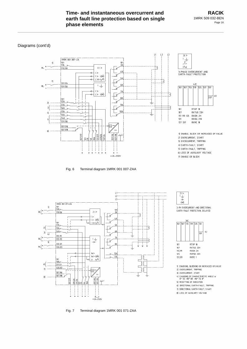
Diagrams (cont’d)
Fig. 6 Terminal diagram 1MRK 001 007-ZAA
Fig. 7 Terminal diagram 1MRK 001 071-ZAA

Time- and instantaneous overcurrent and earth fault line protection based on single phase elements
RACIK1MRK 509 032-BEN
Page 17
Fig. 8 Terminal diagram 1MRK 001 071-VAA

Time- and instantaneous overcurrent and earth fault line protection based on single phase elements
RACIK1MRK 509 032-BEN
Page 18
Protectionassemblies
RACIK is available in the following variants:
RACIK 2 Single-phase overcurrent and earth fault-protection
101 RTXP 18 101 RXTUG 22H 101 RTXP 18 101 RTXP 18
107 RXIDK 2H 107 RXIDK 2H 107 RXTUG 22H 107 RXTUG 22H
113 RXIDG 21H 113 RXIDG 21H 113 RXIDK 2H 113 RXIDK 2H
119 RXIDG 21H 119 RXIDG 21H
125 RXME 18
325 RXME 18
Order No.
Circuitdiagram
Order No.
Circuitdiagram
Order No.
Circuitdiagram
Order No.
Circuitdiagram
1MRK001 006-GA
1MRK001 007-GA
1MRK001 006-HA
1MRK001 007-HA
1MRK001 006-KA
1MRK001 007-KA
1MRK001 006-LA
1MRK001 007-LA
RACIK 3 Two-phase and earth fault protection
101 RTXP 18 101 RXTUG 22H 101 RTXP 18 101 RTXP 18
107 RXIDK 2H 107 RXIDK 2H 107 RXTUG 22H 107 RXTUG 22H
113 RXIDK 2H 113 RXIDK 2H 113 RXIDK 2H 113 RXIDK 2H
119 RXIDG 21H 119 RXIDG 21H 119 RXIDK 2H 119 RXIDK 2H
125 RXIDG 21H 125 RXIDG 21H
131 RXME 18
331 RXME 18
Order No.
Circuitdiagram
Order No.
Circuitdiagram
Order No.
Circuitdiagram
Order No.
Circuitdiagram
1MRK001 006-SA
1MRK001 007-SA
1MRK001 006-TA
1MRK001 007-TA
1MRK001 006-UA
1MRK001 007-UA
1MRK001 006-VA
1MRK001 007-VA
50,51I>I2
1=> 0
107101 113 107101 113 113107101 119
325
125107101 119113
50,51
1=> 0
2I>I2
107101 113 119 107101 113 119 113107101 119 125
331
131107101 113 119 125

Time- and instantaneous overcurrent and earth fault line protection based on single phase elements
RACIK1MRK 509 032-BEN
Page 19
RACIK 4 Three-phase overcurrent and earth fault protection
101 RTXP 18 101 RXTUG 22H 101 RTXP 18 101 RTXP 18
107 RXIDK 2H 107 RXIDK 2H 107 RXTUG 22H 107 RXTUG 22H
113 RXIDK 2H 113 RXIDK 2H 113 RXIDK 2H 113 RXIDK 2H
119 RXIDK 2H 119 RXIDK 2H 119 RXIDK 2H 119 RXIDK 2H
125 RXIDG 21H 125 RXIDG 21H 125 RXIDK 2H 125 RXIDK 2H
131 RXIDG 21H 131 RXIDG 21H
337 RXME 18
337 RXME 18
Order No.
Circuitdiagram
Order No.
Circuitdiagram
Order No.
Circuitdiagram
Order No.
Circuitdiagram
1MRK001 006-NA
1MRK001 007-NA
1MRK001 006-YA
1MRK001 007-YA
1MRK001 006-PA
1MRK001 007-PA
1MRK001 006-ZA
1MRK001 007-ZA
RACIK 223 Two-phase overcurrent and directional earth fault protection for high impedance earthed systems
101 RTXP 18 101 RXTUG 22H 101 RTXP 18 101 RTXP 18
107 RXIDK 2H 107 RXIDK 2H 107 RXTUG 22H 107 RXTUG 22H
113 RXIDK 2H 113 RXIDK 2H 113 RXIDK 2H 113 RXIDK 2H
119 RXPDK 22H 119 RXPDK 22H 119 RXIDK 2H 119 RXIDK 2H
125 RXPDK 22H 125 RXPDK 22H
131 RXME 18
331 RXME 18
Order No.
Circuitdiagram
Order No.
Circuitdiagram
Order No.
Circuitdiagram
Order No.
Circuitdiagram
1MRK001 070-NA
1MRK001 071-NA
1MRK001 070-YA
1MRK001 071-YA
1MRK001 070-PA
1MRK001 071-PA
1MRK001 070-ZA
1MRK001 071-ZA
50,51,3I>I2
1=> 0
51N107101 113 119 125 107101 113 119 125 113107101 119 125 131
337
137107101 113 119 125 131
50,51,
1=> 0
51N2I>I
107101 113 119 107101 113 119 113107101 119 125
331
131107101 113 119 125

Time- and instantaneous overcurrent and earth fault line protection based on single phase elements
RACIK1MRK 509 032-BEN
Page 20
Protection assemblies (cont’d)
Mountingalternatives
All protection can be delivered in the following alternatives:
- on apparatus bars (standard)
- in equipment frame
- in RHGS
- in RHGX
RACIK 224 Three-phase overcurrent and directional earth fault protection for high impedance earthed systems
101 RXTUG 22H 101 RTXP 18 101 RTXP 18
107 RXIDK 2H 107 RXTUG 22H 107 RXTUG 22H
113 RXIDK 2H 113 RXIDK 2H 113 RXIDK 2H
119 RXIDK 2H 119 RXIDK 2H 119 RXIDK 2H
125 RXPDK 22H 125 RXIDK 2H 125 RXIDK 2H
131 RXPDK 22H 131 RXPDK 22H
137 RXME 18
337 RXME 18
Order No.
Circuitdiagram
Order No.
Circuitdiagram
Order No.
Circuitdiagram
1MRK001 070-TA
1MRK001 071-TA
1MRK001 070-UA
1MRK001 071-UA
1MRK001 070-VA
1MRK001 071-VA
50,51,
1=> 0
51N3I>I
107101 113 119 125 113107101 119 125 131
337
137107101 113 119 125 131

Time- and instantaneous overcurrent and earth fault line protection based on single phase elements
RACIK1MRK 509 032-BEN
Page 21
Ordering Specify RACIK Protections
• Quantity
• Ordering number
• Code A, C, H, M
• Desired wording on the lower half of the test switch face platemax. 13 lines with 14 characters per line
Overcurrent relay
Auxiliary voltageFor included auxiliary relays
Mounting
Type Rated currentIr
Filter Article No. Code forphase
Code for earth fault
RXIDK 2H 1 A 50-60 Hz (standard) 1MRK 000 838-AA A1
RXIDK 2H 5 A 50-60 Hz (standard) 1MRK 000 838-HA A6
RXPDK 22H 0,05 A 50-60 Hz (standard) 1MRK 000 844-CA C3
RXPDK 22H 0,2 A 50-60 Hz (standard) 1MRK 000 844-DA C4
RXIDG 2H 0,2 A 50-60 Hz (standard) 1MRK 000 839-AA
Code
24 V dc H5
48-55 V dc H6
110-125 V dc H7
220-250 V dc H8
Mounting alternatives Size Article No. Code
Apparatus bars M10
Equipment frame without door
4U 19” 1MRK 000 137-GA M11
Equipment frame with door
4U 19” 1MRK 000 137-KA M12
RHGX 4 4U 12C RK 927 001-AB M71
RHGX 8 4U 24C RK 927 002-AB M72
RHGX 12 4U 36C RK 927 003-AB M73
RHGX 20 4U 60C RK 927 004-AB M74
RHGS 30 6U x 1/1 19” rack 1MRK 000 315-A M81
RHGS 12 6U x 1/2 19” rack 1MRK 000 315-B M82
RHGS 6 6U x 1/4 19” rack 1MRK 000 315-C M83

Time- and instantaneous overcurrent and earth fault line protection based on single phase elements
RACIK1MRK 509 032-BEN
Page 22
References Auxiliary relays
Time-overcurrent relays RXIDK 2H/RAIDK
Directional time-overcurrent relaysRXPDK/RAPDK
Connection and installation components inCOMBIFLEX
Relay accessoriesCOMBIFLEX
Test systemsCOMBITEST
User’s GuidePhase overcurrent and earth-fault protections,type RAIDK, RAIDG, RAPDK and RACIK
1MRK 508 015-BEN
1MRK 509 002-BEN
1MRK 509 007-BEN
1MRK 513 003-BEN
1MRK 513 004-BEN
1MRK 512 001-BEN
1MRK 509 031-UEN
Manufacturer ABB Automation Products ABSubstation Automation DivisionSE-721 59 VästeråsSwedenTel: +46 (0) 21 342000Fax: +46 (0) 21 146918