Embed Size (px)
Citation preview
Time Response of Reactive CircuitsTime Response of Reactive Circuits
Chapter 15
Thomas L. Floyd
David M. Buchla
DC/AC Fundamentals: A Systems DC/AC Fundamentals: A Systems ApproachApproach
DC/AC Fundamentals: A Systems ApproachThomas L. Floyd
© 2013 by Pearson Higher Education, IncUpper Saddle River, New Jersey 07458 • All Rights Reserved
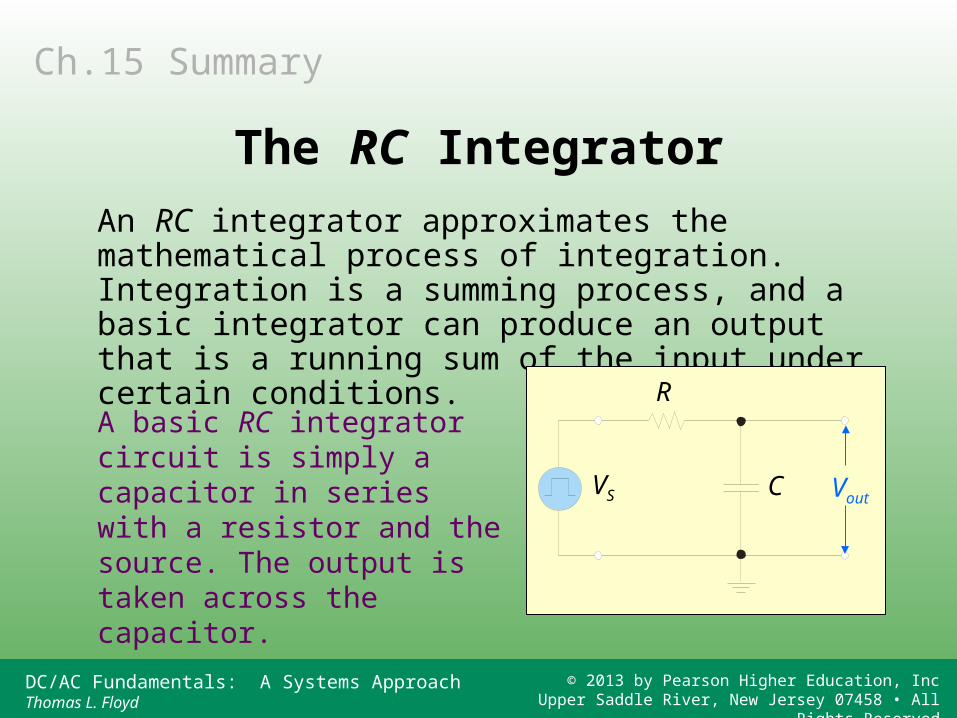
An RC integrator approximates the mathematical process of integration. Integration is a summing process, and a basic integrator can produce an output that is a running sum of the input under certain conditions.
A basic RC integrator circuit is simply a capacitor in series with a resistor and the source. The output is taken across the capacitor.
VS
R
C Vout
Ch.15 Summary
The RC Integrator
DC/AC Fundamentals: A Systems ApproachThomas L. Floyd
© 2013 by Pearson Higher Education, IncUpper Saddle River, New Jersey 07458 • All Rights Reserved
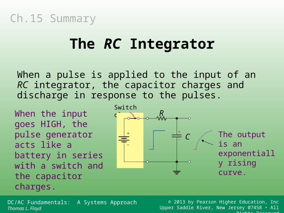
When a pulse is applied to the input of an RC integrator, the capacitor charges and discharge in response to the pulses.
When the input goes HIGH, the pulse generator acts like a battery in series with a switch and the capacitor charges.
Switch closes
The output is an exponentially rising curve.
R
C
Ch.15 Summary
The RC Integrator
DC/AC Fundamentals: A Systems ApproachThomas L. Floyd
© 2013 by Pearson Higher Education, IncUpper Saddle River, New Jersey 07458 • All Rights Reserved
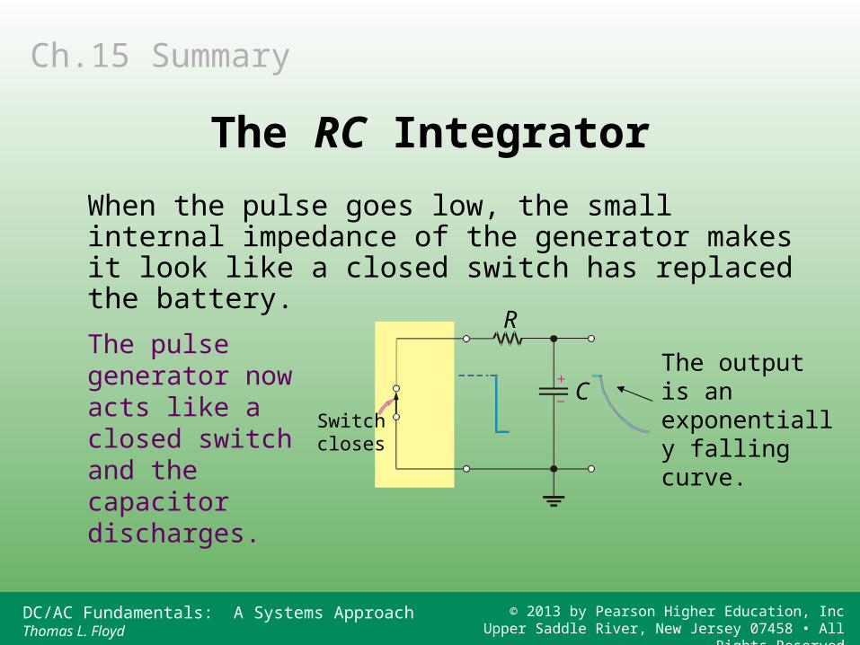
When the pulse goes low, the small internal impedance of the generator makes it look like a closed switch has replaced the battery.
The pulse generator now acts like a closed switch and the capacitor discharges.
Ch.15 Summary
The RC Integrator
The output is an exponentially falling curve.
R
CSwitch closes
DC/AC Fundamentals: A Systems ApproachThomas L. Floyd
© 2013 by Pearson Higher Education, IncUpper Saddle River, New Jersey 07458 • All Rights Reserved
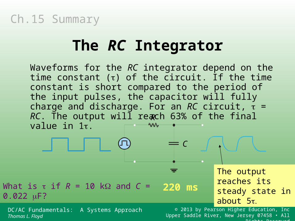
Waveforms for the RC integrator depend on the time constant () of the circuit. If the time constant is short compared to the period of the input pulses, the capacitor will fully charge and discharge. For an RC circuit, = RC. The output will reach 63% of the final value in 1.
R
C
What is if R = 10 k and C = 0.022 F? 220 ms
The output reaches its steady state in about 5
Ch.15 Summary
The RC Integrator
DC/AC Fundamentals: A Systems ApproachThomas L. Floyd
© 2013 by Pearson Higher Education, IncUpper Saddle River, New Jersey 07458 • All Rights Reserved
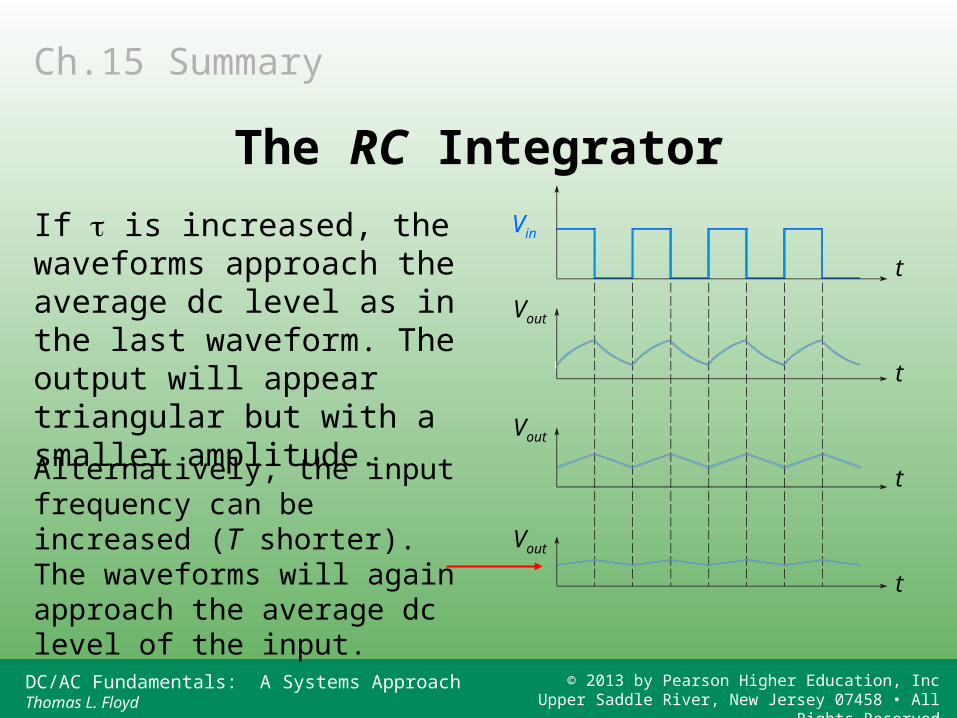
If is increased, the waveforms approach the average dc level as in the last waveform. The output will appear triangular but with a smaller amplitude.
Alternatively, the input frequency can be increased (T shorter). The waveforms will again approach the average dc level of the input.
t
t
t
t
Vin
Vout
Vout
Vout
Ch.15 Summary
The RC Integrator
DC/AC Fundamentals: A Systems ApproachThomas L. Floyd
© 2013 by Pearson Higher Education, IncUpper Saddle River, New Jersey 07458 • All Rights Reserved
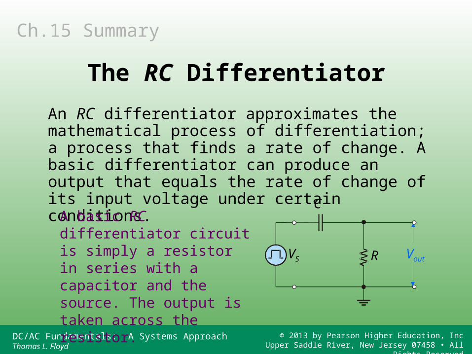
An RC differentiator approximates the mathematical process of differentiation; a process that finds a rate of change. A basic differentiator can produce an output that equals the rate of change of its input voltage under certain conditions.
A basic RC differentiator circuit is simply a resistor in series with a capacitor and the source. The output is taken across the resistor.
Ch.15 Summary
The RC Differentiator
VS R
C
Vout
DC/AC Fundamentals: A Systems ApproachThomas L. Floyd
© 2013 by Pearson Higher Education, IncUpper Saddle River, New Jersey 07458 • All Rights Reserved
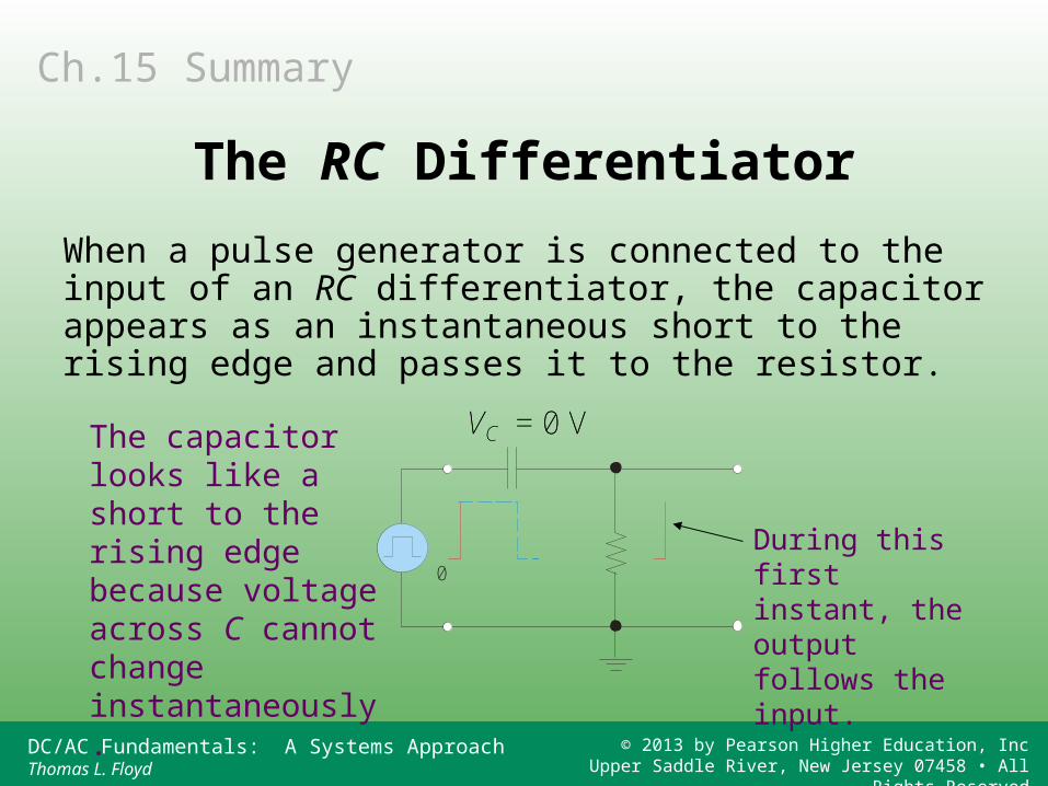
When a pulse generator is connected to the input of an RC differentiator, the capacitor appears as an instantaneous short to the rising edge and passes it to the resistor.
The capacitor looks like a short to the rising edge because voltage across C cannot change instantaneously.
During this first instant, the output follows the input.
Ch.15 Summary
The RC Differentiator
0
VC = 0 V
0
VC = 0 V
DC/AC Fundamentals: A Systems ApproachThomas L. Floyd
© 2013 by Pearson Higher Education, IncUpper Saddle River, New Jersey 07458 • All Rights Reserved
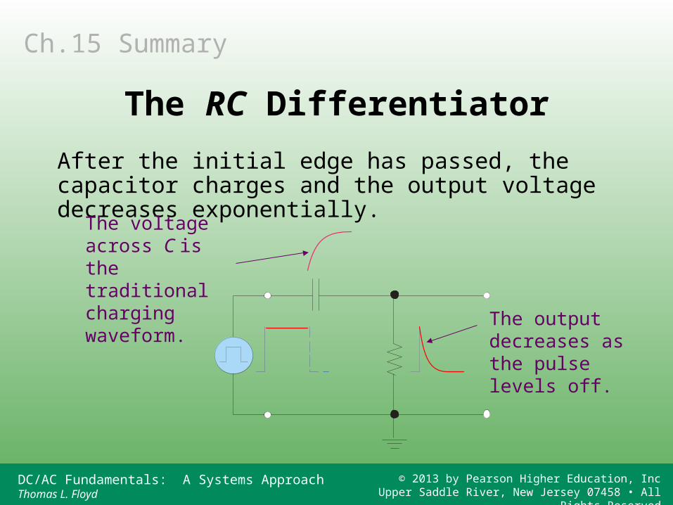
After the initial edge has passed, the capacitor charges and the output voltage decreases exponentially.
The voltage across C is the traditional charging waveform. The output
decreases as the pulse levels off.
Ch.15 Summary
The RC Differentiator
DC/AC Fundamentals: A Systems ApproachThomas L. Floyd
© 2013 by Pearson Higher Education, IncUpper Saddle River, New Jersey 07458 • All Rights Reserved
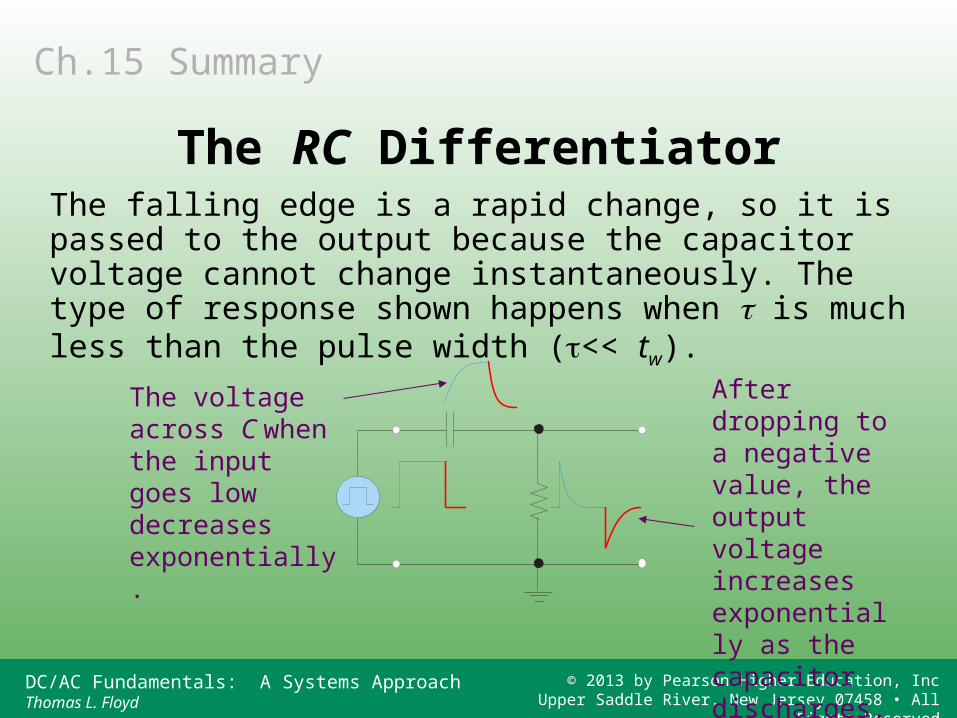
The falling edge is a rapid change, so it is passed to the output because the capacitor voltage cannot change instantaneously. The type of response shown happens when is much less than the pulse width (<< tw).
The voltage across C when the input goes low decreases exponentially.
After dropping to a negative value, the output voltage increases exponentially as the capacitor discharges.
Ch.15 Summary
The RC Differentiator
DC/AC Fundamentals: A Systems ApproachThomas L. Floyd
© 2013 by Pearson Higher Education, IncUpper Saddle River, New Jersey 07458 • All Rights Reserved
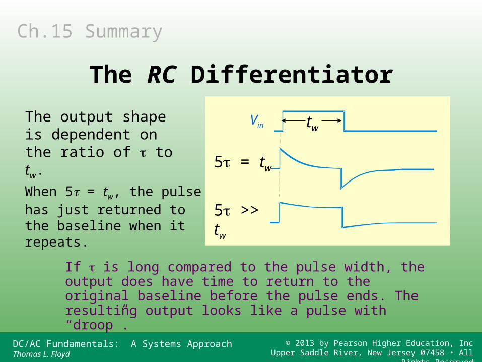
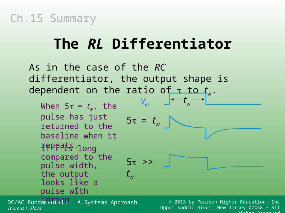
If is long compared to the pulse width, the output does have time to return to the original baseline before the pulse ends. The resulting output looks like a pulse with “droop”.
Vin
5 = tw
5 >> tw
tw
When 5 = tw, the pulse has just returned to the baseline when it repeats.
The output shape is dependent on the ratio of to tw.
Ch.15 Summary
The RC Differentiator
DC/AC Fundamentals: A Systems ApproachThomas L. Floyd
© 2013 by Pearson Higher Education, IncUpper Saddle River, New Jersey 07458 • All Rights Reserved
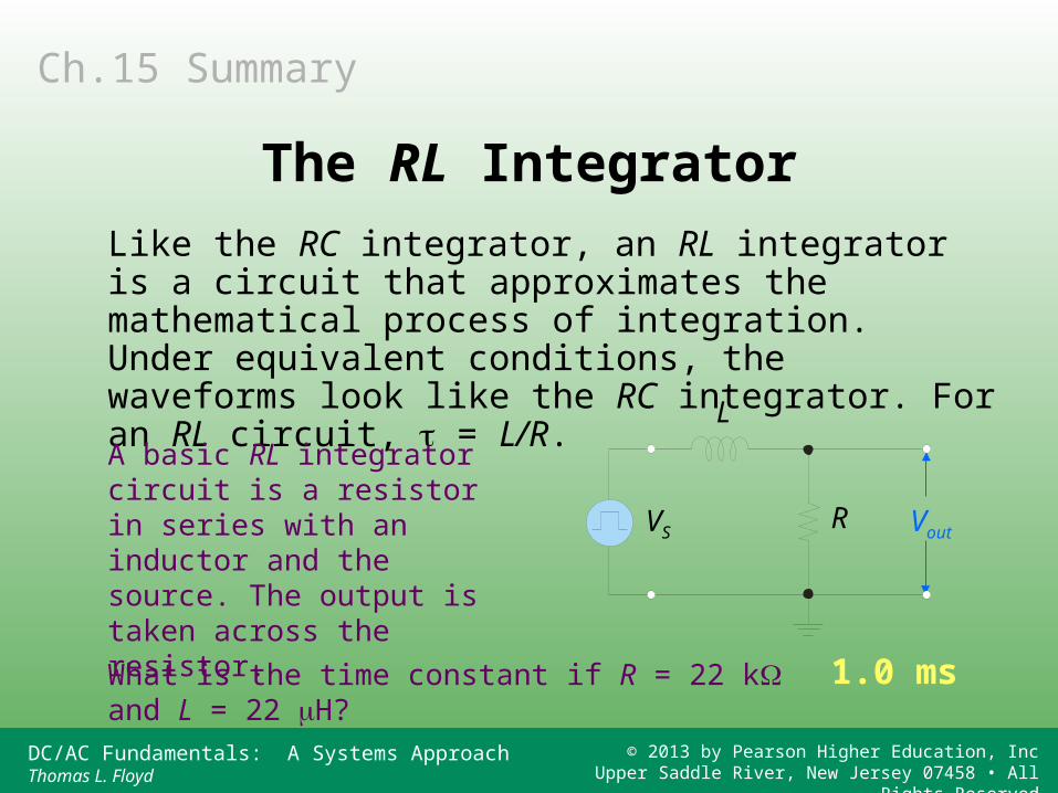
Like the RC integrator, an RL integrator is a circuit that approximates the mathematical process of integration. Under equivalent conditions, the waveforms look like the RC integrator. For an RL circuit, = L/R.
A basic RL integrator circuit is a resistor in series with an inductor and the source. The output is taken across the resistor.
VSR
L
Vout
What is the time constant if R = 22 k and L = 22 H? 1.0 ms
Ch.15 Summary
The RL Integrator
DC/AC Fundamentals: A Systems ApproachThomas L. Floyd
© 2013 by Pearson Higher Education, IncUpper Saddle River, New Jersey 07458 • All Rights Reserved
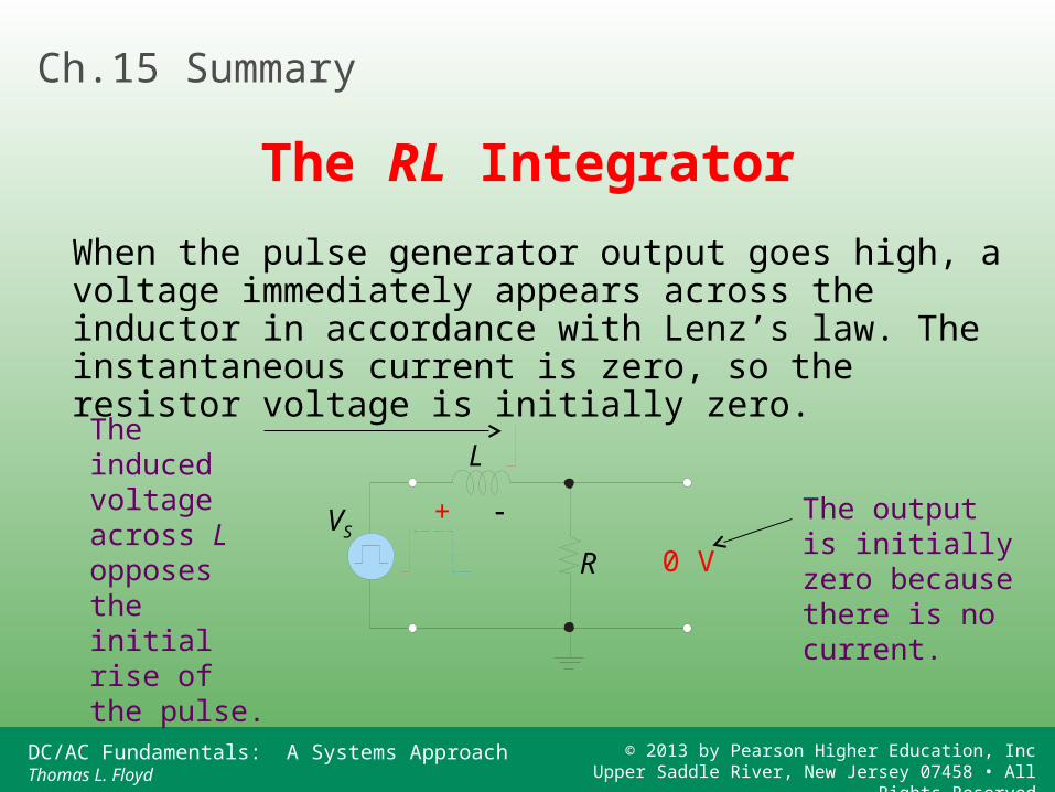
When the pulse generator output goes high, a voltage immediately appears across the inductor in accordance with Lenz’s law. The instantaneous current is zero, so the resistor voltage is initially zero.
VS
R
L
+
0 V
Ch.15 Summary
The RL Integrator
The output is initially zero because there is no current.
The induced voltage across L opposes the initial rise of the pulse.
DC/AC Fundamentals: A Systems ApproachThomas L. Floyd
© 2013 by Pearson Higher Education, IncUpper Saddle River, New Jersey 07458 • All Rights Reserved
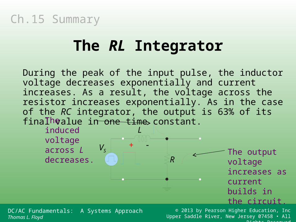
During the peak of the input pulse, the inductor voltage decreases exponentially and current increases. As a result, the voltage across the resistor increases exponentially. As in the case of the RC integrator, the output is 63% of its final value in one time constant.
VS
R
L
+
Ch.15 Summary
The RL Integrator
The induced voltage across L decreases.
The output voltage increases as current builds in the circuit.
DC/AC Fundamentals: A Systems ApproachThomas L. Floyd
© 2013 by Pearson Higher Education, IncUpper Saddle River, New Jersey 07458 • All Rights Reserved
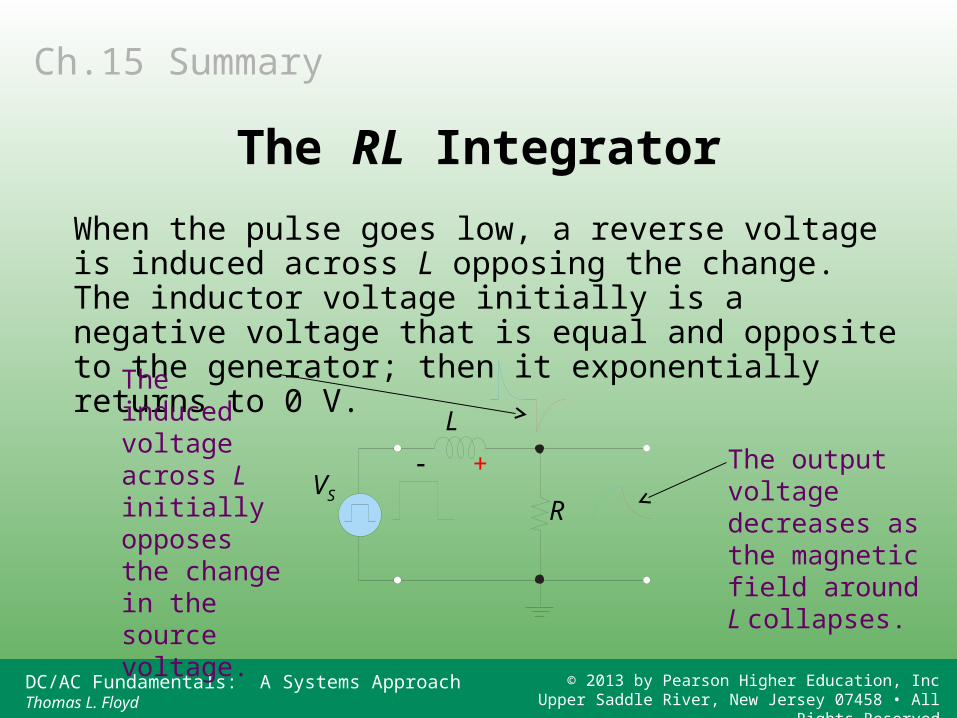
When the pulse goes low, a reverse voltage is induced across L opposing the change. The inductor voltage initially is a negative voltage that is equal and opposite to the generator; then it exponentially returns to 0 V.
VSR
L
+
Ch.15 Summary
The RL Integrator
The output voltage decreases as the magnetic field around L collapses.
The induced voltage across L initially opposes the change in the source voltage.
DC/AC Fundamentals: A Systems ApproachThomas L. Floyd
© 2013 by Pearson Higher Education, IncUpper Saddle River, New Jersey 07458 • All Rights Reserved
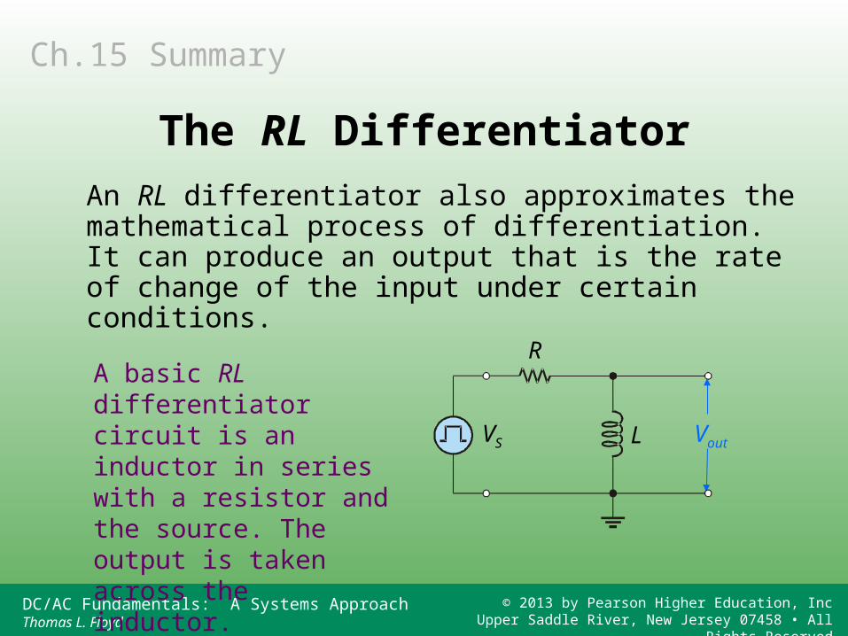
An RL differentiator also approximates the mathematical process of differentiation. It can produce an output that is the rate of change of the input under certain conditions.
A basic RL differentiator circuit is an inductor in series with a resistor and the source. The output is taken across the inductor.
VS L
R
Vout
Ch.15 Summary
The RL Differentiator
DC/AC Fundamentals: A Systems ApproachThomas L. Floyd
© 2013 by Pearson Higher Education, IncUpper Saddle River, New Jersey 07458 • All Rights Reserved
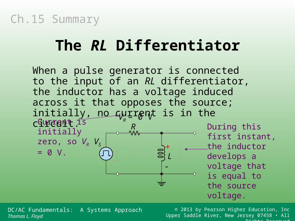
When a pulse generator is connected to the input of an RL differentiator, the inductor has a voltage induced across it that opposes the source; initially, no current is in the circuit.
During this first instant, the inductor develops a voltage that is equal to the source voltage.
VR = 0 V
VS
L
RCurrent is initially zero, so VR = 0 V.
+
Ch.15 Summary
The RL Differentiator
DC/AC Fundamentals: A Systems ApproachThomas L. Floyd
© 2013 by Pearson Higher Education, IncUpper Saddle River, New Jersey 07458 • All Rights Reserved
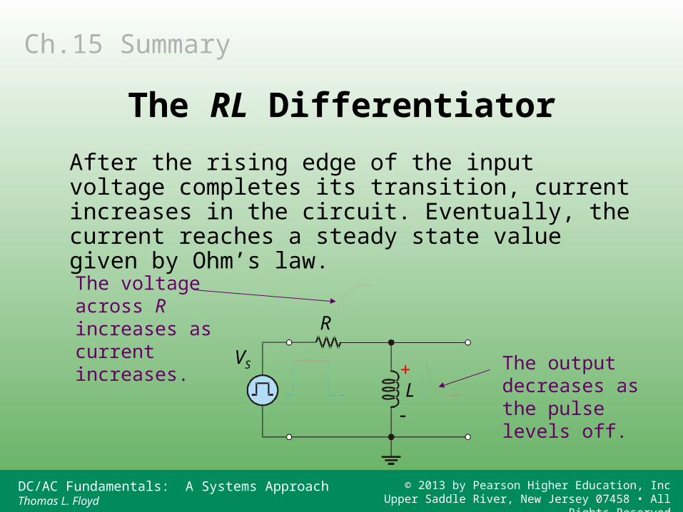
After the rising edge of the input voltage completes its transition, current increases in the circuit. Eventually, the current reaches a steady state value given by Ohm’s law.
The output decreases as the pulse levels off.
VS
L
R
The voltage across R increases as current increases.
+
Ch.15 Summary
The RL Differentiator
DC/AC Fundamentals: A Systems ApproachThomas L. Floyd
© 2013 by Pearson Higher Education, IncUpper Saddle River, New Jersey 07458 • All Rights Reserved
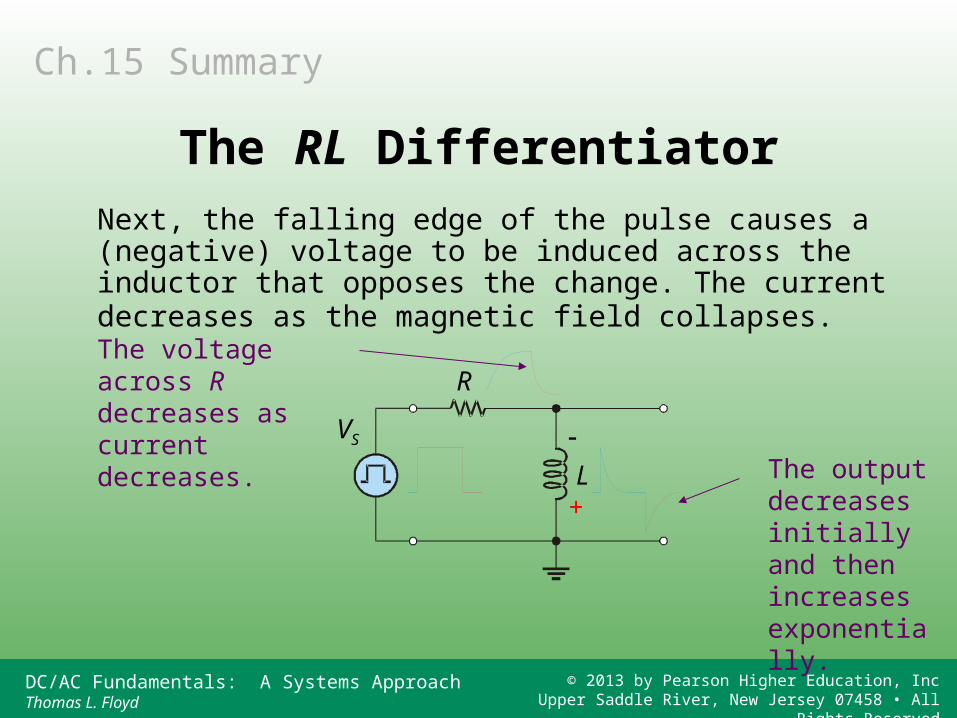
Next, the falling edge of the pulse causes a (negative) voltage to be induced across the inductor that opposes the change. The current decreases as the magnetic field collapses.
The output decreases initially and then increases exponentially.
VS
L
RThe voltage across R decreases as current decreases.
+
Ch.15 Summary
The RL Differentiator
DC/AC Fundamentals: A Systems ApproachThomas L. Floyd
© 2013 by Pearson Higher Education, IncUpper Saddle River, New Jersey 07458 • All Rights Reserved
If is long compared to the pulse width, the output looks like a pulse with “droop”.
Vin
5= tw
5 >> tw
twWhen 5 = tw, the pulse has just returned to the baseline when it repeats.
As in the case of the RC differentiator, the output shape is dependent on the ratio of to tw.
Ch.15 Summary
The RL Differentiator
DC/AC Fundamentals: A Systems ApproachThomas L. Floyd
© 2013 by Pearson Higher Education, IncUpper Saddle River, New Jersey 07458 • All Rights Reserved
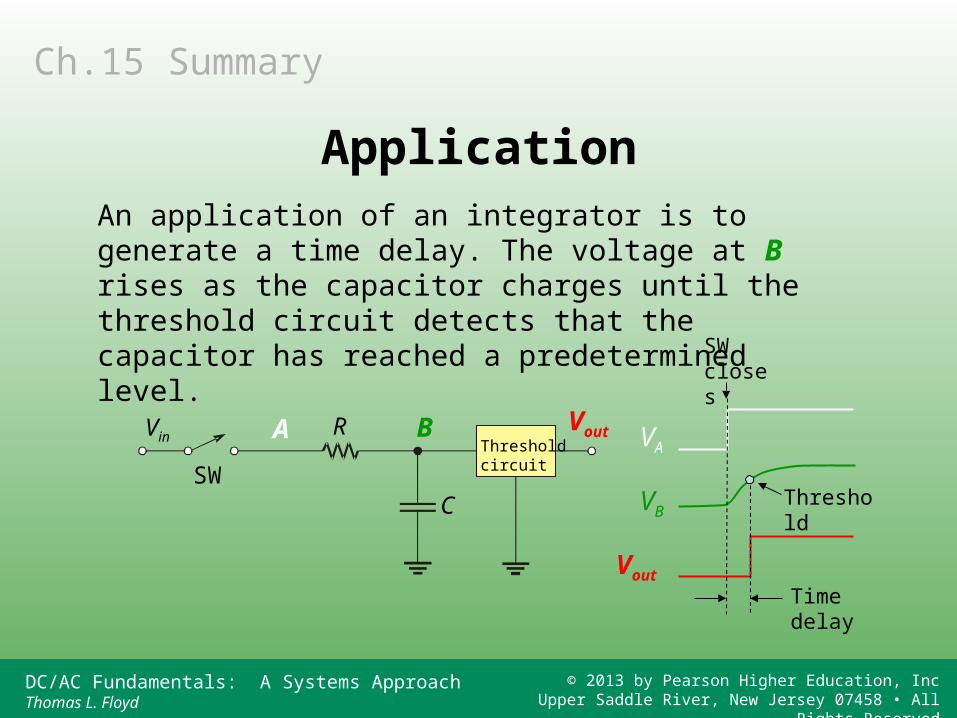
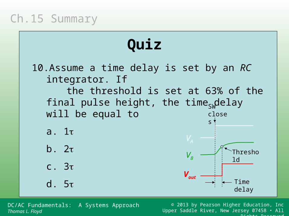
An application of an integrator is to generate a time delay. The voltage at B rises as the capacitor charges until the threshold circuit detects that the capacitor has reached a predetermined level.
SW closes
Threshold
Time delay
R VoutVin A B VA
VB
Vout
Threshold circuitSW
C
Ch.15 Summary
Application
DC/AC Fundamentals: A Systems ApproachThomas L. Floyd
© 2013 by Pearson Higher Education, IncUpper Saddle River, New Jersey 07458 • All Rights Reserved
A circuit producing an output that approaches the mathematical integral of the input.
A fixed time interval, set by R and C, or R and L values, that determines the time response of a circuit.
An interval equal to approximately five time constants.
Ch.15 Summary
Key Terms
Integrator
Time constant
Transient time
DC/AC Fundamentals: A Systems ApproachThomas L. Floyd
© 2013 by Pearson Higher Education, IncUpper Saddle River, New Jersey 07458 • All Rights Reserved
The equilibrium condition of a circuit that occurs after an initial transient time.
A circuit producing an output that approaches the mathematical derivative of the input.
Ch.15 Summary
Key Terms
Steady state
Differentiator
DC/AC Fundamentals: A Systems ApproachThomas L. Floyd
© 2013 by Pearson Higher Education, IncUpper Saddle River, New Jersey 07458 • All Rights Reserved
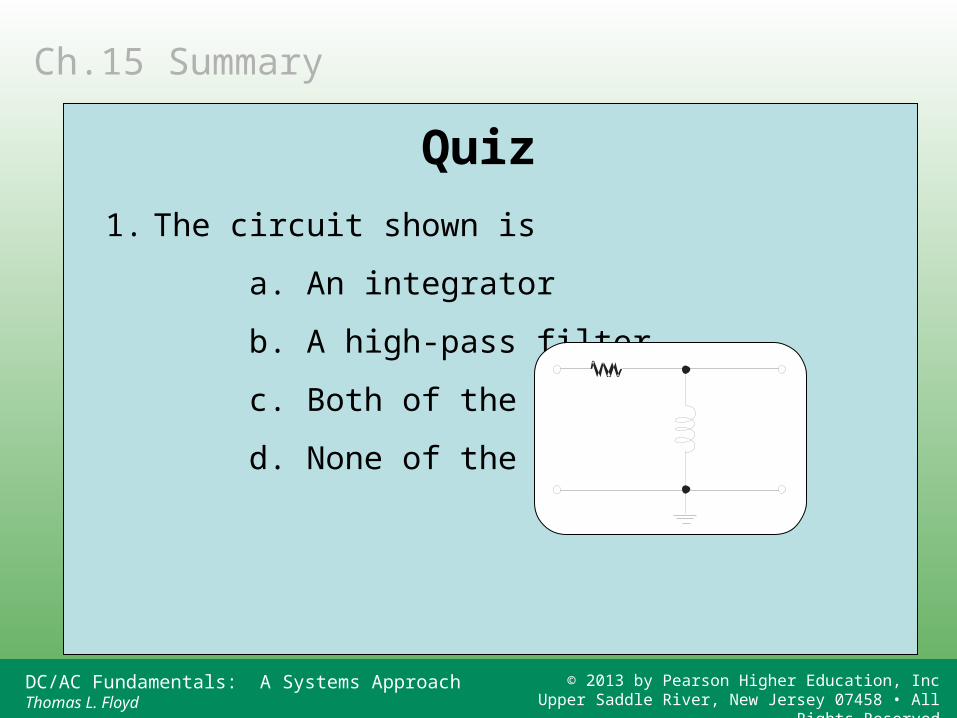
1. The circuit shown is
a. An integrator
b. A high-pass filter
c. Both of the above
d. None of the above
Ch.15 Summary
Quiz
DC/AC Fundamentals: A Systems ApproachThomas L. Floyd
© 2013 by Pearson Higher Education, IncUpper Saddle River, New Jersey 07458 • All Rights Reserved
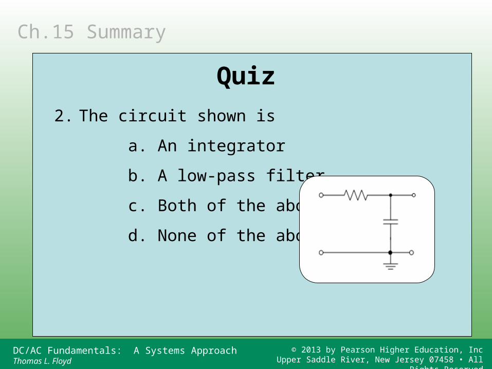
2. The circuit shown is
a. An integrator
b. A low-pass filter
c. Both of the above
d. None of the above
Ch.15 Summary
Quiz
DC/AC Fundamentals: A Systems ApproachThomas L. Floyd
© 2013 by Pearson Higher Education, IncUpper Saddle River, New Jersey 07458 • All Rights Reserved
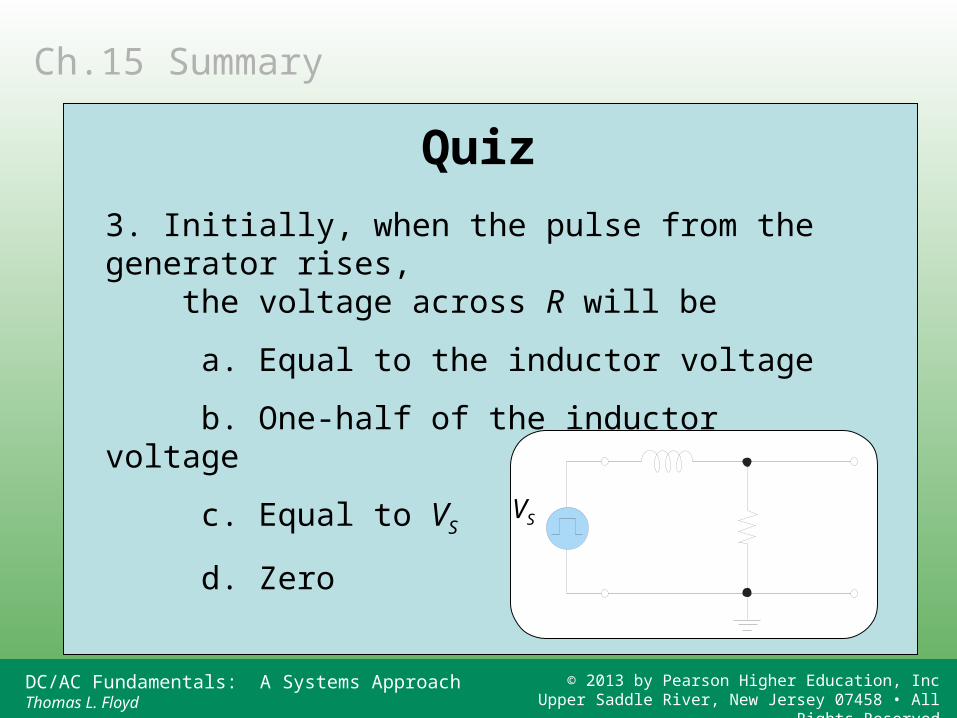
3. Initially, when the pulse from the generator rises, the voltage across R will be
a. Equal to the inductor voltage
b. One-half of the inductor voltage
c. Equal to VS
d. Zero VS
Ch.15 Summary
Quiz
DC/AC Fundamentals: A Systems ApproachThomas L. Floyd
© 2013 by Pearson Higher Education, IncUpper Saddle River, New Jersey 07458 • All Rights Reserved
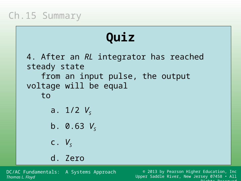
4. After an RL integrator has reached steady state from an input pulse, the output voltage will be equal to
a. 1/2 VS
b. 0.63 VS
c. VS
d. Zero
Ch.15 Summary
Quiz
DC/AC Fundamentals: A Systems ApproachThomas L. Floyd
© 2013 by Pearson Higher Education, IncUpper Saddle River, New Jersey 07458 • All Rights Reserved
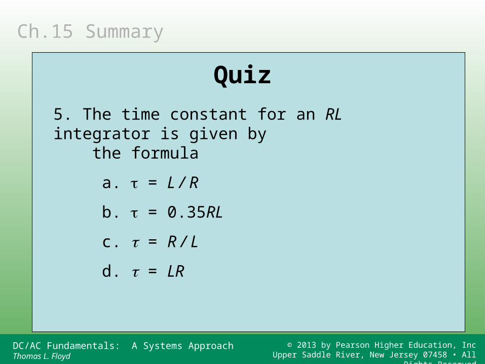
5. The time constant for an RL integrator is given by the formula
a. = L / R
b. = 0.35RL
c. = R / L
d. = LR
Ch.15 Summary
Quiz
DC/AC Fundamentals: A Systems ApproachThomas L. Floyd
© 2013 by Pearson Higher Education, IncUpper Saddle River, New Jersey 07458 • All Rights Reserved
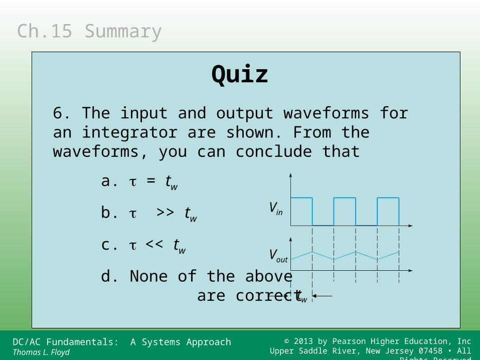
6. The input and output waveforms for an integrator are shown. From the waveforms, you can conclude that
a. = tw
b. >> tw
c. << tw
d. None of the above are correct
Vin
Vout
tw
Ch.15 Summary
Quiz
DC/AC Fundamentals: A Systems ApproachThomas L. Floyd
© 2013 by Pearson Higher Education, IncUpper Saddle River, New Jersey 07458 • All Rights Reserved
7. If a 20 k resistor is in series with a 0.1 F capacitor, the time constant is
a. 200 ms
b. 0.5 ms
c. 1.0 ms
d. None of the above
Ch.15 Summary
Quiz
DC/AC Fundamentals: A Systems ApproachThomas L. Floyd
© 2013 by Pearson Higher Education, IncUpper Saddle River, New Jersey 07458 • All Rights Reserved
8. After a single input transition from 0 to 10 V, the output of a differentiator will return to 0 V in
a. Less than one time constant
b. One time constant
c. Approximately five time constants
d. Approximately ten time constants
Ch.15 Summary
Quiz
DC/AC Fundamentals: A Systems ApproachThomas L. Floyd
© 2013 by Pearson Higher Education, IncUpper Saddle River, New Jersey 07458 • All Rights Reserved
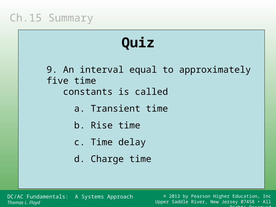
9. An interval equal to approximately five time constants is called
a. Transient time
b. Rise time
c. Time delay
d. Charge time
Ch.15 Summary
Quiz
DC/AC Fundamentals: A Systems ApproachThomas L. Floyd
© 2013 by Pearson Higher Education, IncUpper Saddle River, New Jersey 07458 • All Rights Reserved
10.Assume a time delay is set by an RC integrator. If the threshold is set at 63% of the final pulse height,
the time delay will be equal to
a. 1
b. 2
c. 3
d. 5
SW closes
Threshold
Time delay
VA
VB
Vout
Ch.15 Summary
Quiz
DC/AC Fundamentals: A Systems ApproachThomas L. Floyd
© 2013 by Pearson Higher Education, IncUpper Saddle River, New Jersey 07458 • All Rights Reserved
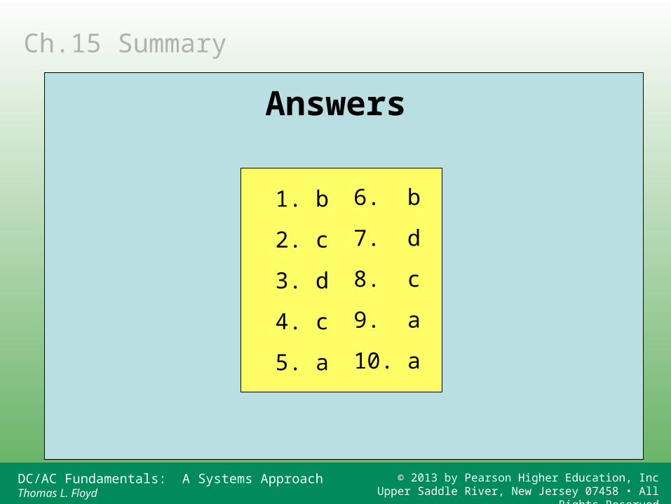
1. b
2. c
3. d
4. c
5. a
6. b
7. d
8. c
9. a
10. a
Ch.15 Summary
Answers