Embed Size (px)
Citation preview
11 ECNDT 2014 Prague, 6-10 October 2014
TIME REVERSAL SIGNAL PROCESSING IN ACOUSTIC EMISSION
Zdenek PREVOROVSKY1, Josef KROFTA1,Milan CHLADA1, Jan KOBER1,
and Serge DOS SANTOS2
1 - Institute of Thermomechanics Academy of Sciences CR, Prague, Czech Republic
www.it.cas.cz, E-mail: [email protected]
2 - INSA , Université François Rabelaise, Blois, France
1

OUTLINE
1. AE Source Location and Identification using Time Reversal
2. TR AE Signal Deconvolution (TRAED)
3. Transfer of AE signal and the source reconstruction on
similar body without AE source
4. Conclusions for AE signal analysis on remote objects
Z. Prevorovsky, J. Krofta, M. Chlada1, Z. Farova, V. Kus:
Progressive Approaches to Localization and Identification of AE Sources.
30 EWGAE / 7 ICAE 2012, Granada, Spain, 12-15 Sept. 2012, http://www.ndt.net/EWGAE-ICAE2012
11 ECNDT 2014 Prague, 6-10 October 2014 2
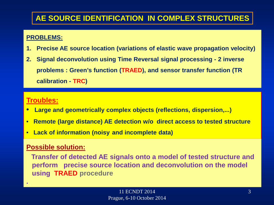
AE SOURCE IDENTIFICATION IN COMPLEX STRUCTURES
Troubles: • Large and geometrically complex objects (reflections, dispersion,...)
• Remote (large distance) AE detection w/o direct access to tested structure
• Lack of information (noisy and incomplete data)
PROBLEMS:
1. Precise AE source location (variations of elastic wave propagation velocity)
2. Signal deconvolution using Time Reversal signal processing - 2 inverse
problems : Green’s function (TRAED), and sensor transfer function (TR
calibration - TRC)
Possible solution:Transfer of detected AE signals onto a model of tested structure and perform precise source location and deconvolution on the modelusing TRAED procedure
.311 ECNDT 2014
Prague, 6-10 October 2014

B. E.. Anderson, M. Griffa, C. Larmat, T.J. Ulrich, P.A. Johnson: Time Reversal(Acoustics Today, Volume 4, Issue 1, January 2008)
2 implementations of TR:
source emission
a) standard TR
b) reciprocal TR
steps in TR
Time Reversal Mirrors (TRM)
- Improvement of S/N ratio- Space focusing of waves
- Source signal reconstruction
11 ECNDT 2014 Prague, 6-10 October 2014 4
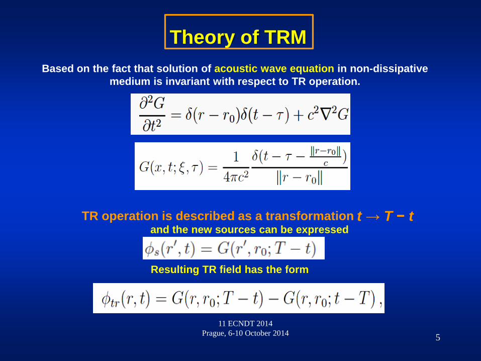
Based on the fact that solution of acoustic wave equation in non-dissipative medium is invariant with respect to TR operation.
Theory of TRM
TR operation is described as a transformation t → T − tand the new sources can be expressed
Resulting TR field has the form
11 ECNDT 2014 Prague, 6-10 October 2014 5

AE Signal Deconvolution using Time Reversal Mirrors
A point source function s(t) at the position r0 and a receiver at position ri. The signal detected at ri on time t arises from two convolutions:SG(t)
Detected AE signal is then time reversed and rebroadcast from the position ri to r0.
Resulting TR signal is expressed as multiple convolution:
Which is in the frequency domain
After inverse FT we obtain the TR signal reconstructed at the source
11 ECNDT 2014 Prague, 6-10 October 2014 6
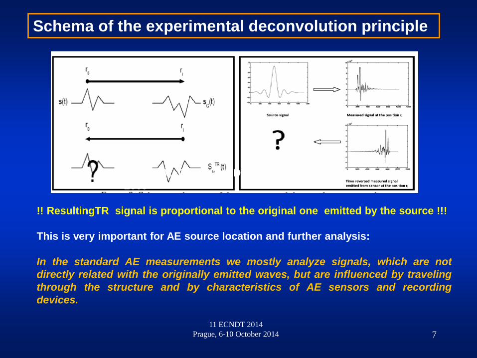
Schema of the experimental deconvolution principle
!! ResultingTR signal is proportional to the original one emitted by the source !!!
This is very important for AE source location and further analysis:
In the standard AE measurements we mostly analyze signals, which are notdirectly related with the originally emitted waves, but are influenced by travelingthrough the structure and by characteristics of AE sensors and recordingdevices.
JOURNAL OF APPLIED PHYSICS 106, 113504 2009
11 ECNDT 2014 Prague, 6-10 October 2014 7
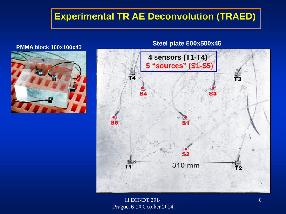
Experimental TR AE Deconvolution (TRAED)
4 sensors (T1-T4) 5 “sources” (S1-S5)
PMMA block 100x100x40 Steel plate 500x500x45
11 ECNDT 2014 Prague, 6-10 October 2014
8

TR AE Source Location
T1+t1=T, T2+t2=T, T3+t3=T11 ECNDT 2014
Prague, 6-10 October 2014
PERFECT SYNCHRONIZATION OF TR ARRIVAL TIMES AT THE SOURCE
9

EFFECT OF INACCURATE SOURCE LOCATIONSURFACE SCANNING a) by LASER interferometer, b) AE sensor (reciprocal TR)
2.95 3 3.05
x 104
-10
-5
0
5
10
2.98 2.99 3 3.01 3.02 3.03
x 104
-3
-2
-1
0
1
2
3
4
RECEIVER SHIFTS
SUMMATION OF TR SIGNAS
0 mm 10 mm 20 mm
Emitted signal (85 kHz)
11 ECNDT 2014 Prague, 6-10 October 2014
10

AE IN FATIGUE TESTS OF AIRCRAFT WING FLANGE
date/time: 12081800 used sensors: 1 3 4 5 7 9
50 100 150 200 250 300
100
200
300
400
500
600
700
800
900
date/time: 12091400 used sensors: 1 3 4 5 7 9
50 100 150 200 250 300
100
200
300
400
500
600
700
800
900
11 ECNDT 2014 Prague, 6-10 October 2014
11
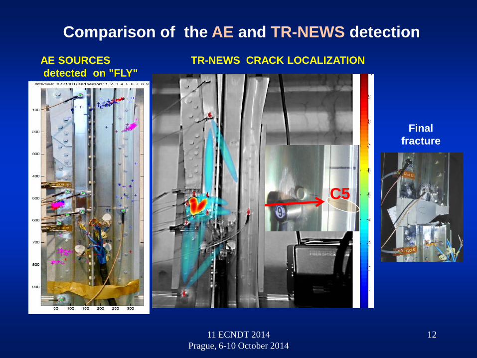
AE SOURCESdetected on "FLY"
TR-NEWS CRACK LOCALIZATION
C5
Final fracture
Comparison of the AE and TR-NEWS detection
11 ECNDT 2014 Prague, 6-10 October 2014
12

TYPICAL AE SOURCESARE CRACKS AT RIVETS
TRAED EXPERIMENTAL SETUP
11 ECNDT 2014 Prague, 6-10 October 2014
13

3-D NUMERICAL MODELING OF WAVE PROPAGATIONIN THE FLANGE CUTOFF
AE SOURCE (Ricker pulse)
11 ECNDT 2014 Prague, 6-10 October 2014
14
SIGNALS IN 10 POINTS

6200 6400 6600 6800 7000 7200 7400 7600 7800 8000 8200-5
0
5
6200 6400 6600 6800 7000 7200 7400 7600 7800 8000 8200-1
-0.5
0
0.5
1
6200 6400 6600 6800 7000 7200 7400 7600 7800 8000 8200-2
-1
0
1
2
6200 6400 6600 6800 7000 7200 7400 7600 7800 8000 8200-2
-1
0
1
2
6200 6400 6600 6800 7000 7200 7400 7600 7800 8000 8200-2
-1
0
1
2
6 6.05 6.1 6.15 6.2
x 104
-20
0
20
6 6.05 6.1 6.15 6.2
x 104
-20
0
20
6.05 6.1 6.15 6.2
x 104
-20
0
20
6 6.05 6.1 6.15 6.2
x 104
-20
0
20
6 6.05 6.1 6.15 6.2
x 104
-20
0
20
Source S1AE signals from T1-T4
T1
T2
T3
T4
LASER
TIME REVERSALRECONSTRUCTION
11 ECNDT 2014 Prague, 6-10 October 2014
TRAED TESTING OF THE WING FLANGE5 PEN-TEST SOURCES (S1-S5)
4 AE TRANSDUCERS (T1-T4)
LASER
15
6200 6400 6600 6800 7000 7200 7400 7600 7800 8000 8200-2
0
2
6200 6400 6600 6800 7000 7200 7400 7600 7800 8000 8200-2
0
2
6200 6400 6600 6800 7000 7200 7400 7600 7800 8000 8200
-2
0
2
6200 6400 6600 6800 7000 7200 7400 7600 7800 8000 8200-2
0
2
6 6.05 6.1 6.15 6.2
x 104
-2
0
2
6 6.05 6.1 6.15 6.2
x 104
-1
0
1
2
6 6.05 6.1 6.15 6.2
x 104
-1
0
1
2
6 6.05 6.1 6.15 6.2
x 104
-2
0
2
6 6.05 6.1 6.15 6.2
x 104
-1
0
1
2
6 6.02 6.04 6.06 6.08 6.1
x 104
-2
0
2
6 6.02 6.04 6.06 6.08 6.1
x 104
-1
0
1
6 6.02 6.04 6.06 6.08 6.1
x 104
-2
0
2
6 6.02 6.04 6.06 6.08 6.1
x 104
-2
0
2
6 6.02 6.04 6.06 6.08 6.1
x 104
-1
0
1
2
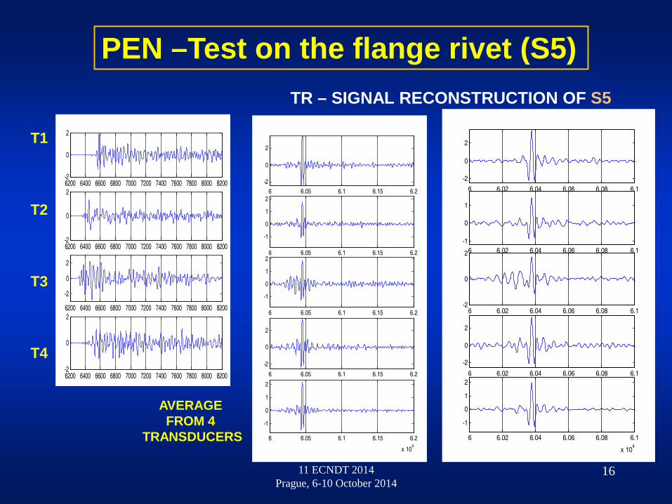
PEN –Test on the flange rivet (S5)
T1
T2
T3
T4
AVERAGEFROM 4
TRANSDUCERS
TR – SIGNAL RECONSTRUCTION OF S5
11 ECNDT 2014 Prague, 6-10 October 2014
16
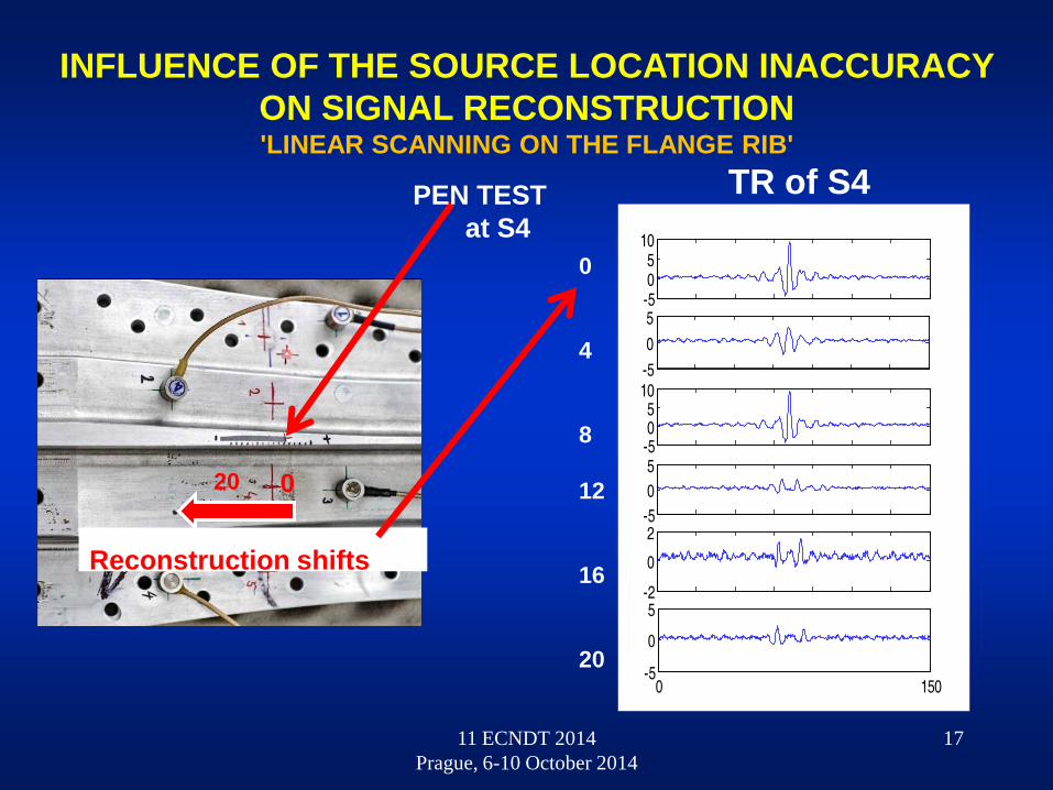
INFLUENCE OF THE SOURCE LOCATION INACCURACY ON SIGNAL RECONSTRUCTION'LINEAR SCANNING ON THE FLANGE RIB'
PEN TESTat S4
020
Reconstruction shifts
-505
10
-505
10-505
-505
-2
0
2
0 150-5
0
5
TR of S4
0
4
8
12
16
20
11 ECNDT 2014 Prague, 6-10 October 2014
17

AE SOURCE LOCATION ACCURACYFocusing of TR signal at the source
'LINEAR SCANNING ON THE FLANGE RIB'
11 ECNDT 2014 Prague, 6-10 October 2014
amplitude
18

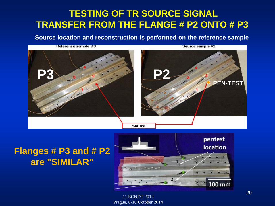
PEN – TESTS ON THE ONE FLANGE (SOURCE SAMPLE) ARE RECONSTRUCTED ON
OTHER (REFERENCE SAMPLE) of SIMILAR GEOMETRY AND
THE SAME SENSORS PLACEMENT.
IT CAN BE USEFUL e.g.ON FLYING AIRCRAFT OR SATELITE PARTS, HAVING
THEIR 'GROUND COPY'
TRANSFER OF TR AE DATA ONTO A SIMILAR PART3 BROKEN PARTS OF THE AIRCRAFT WING FLANGES P1, P2, P3
11 ECNDT 2014 Prague, 6-10 October 2014
19
11 ECNDT 2014 Prague, 6-10 October 2014
TESTING OF TR SOURCE SIGNALTRANSFER FROM THE FLANGE # P2 ONTO # P3 Source location and reconstruction is performed on the reference sample
PEN-TEST
20
Flanges # P3 and # P2are "SIMILAR"
P3 P2

Sample # P1
Sample # P3
11 ECNDT 2014 Prague, 6-10 October 2014
21
P1
P3
DIFFERENCES BETWEEN FLANGES # P1 and # P3 or # P2TR signal transfer P1 P3, P2 failed
Big rivet holes lead toadditional reflections,
which influences resultingTR signal composition
Tr 1Tr 2
Tr 3
Tr 4
yx
11 ECNDT 2014 Prague, 6-10 October 2014
Tr 1
Tr 3
Tr 2
Tr 4
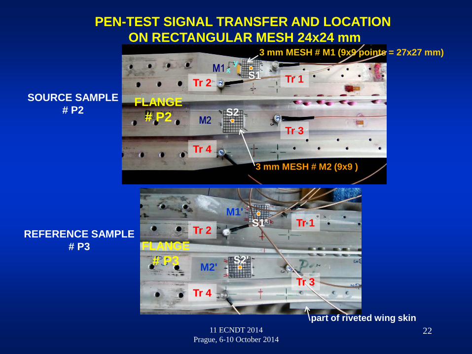
SOURCE SAMPLE# P2
REFERENCE SAMPLE# P3
3 mm MESH # M1 (9x9 points = 27x27 mm)
3 mm MESH # M2 (9x9 )
M1'
M2'
FLANGE# P2
FLANGE# P3
part of riveted wing skin
S1
S2
S2'
S1'
PEN-TEST SIGNAL TRANSFER AND LOCATION ON RECTANGULAR MESH 24x24 mm
22

11 ECNDT 2014 Prague, 6-10 October 2014
SCANNING OF TRANSFER MESHES USING LASER INTERFEROMETERMOUNTED ON 3-D ULTRASONIC SCANNER
by 3 mm steps in both directions
23
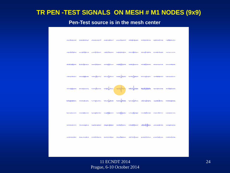
TR Pen-Test signals were transmitted by transducers T1-T4 and maximal TR amplitude received by interferometer indicates precise original source position
11 ECNDT 2014 Prague, 6-10 October 2014
24
TR PEN -TEST SIGNALS ON MESH # M1 NODES (9x9)Pen-Test source is in the mesh center

TR scan of mesh M1 on the flange P2 - T1 emits TR signal. Source location is in the center
TR scan of flange P2, mesh M1 – emitter T2
11 ECNDT 2014 Prague, 6-10 October 2014
25
RESULTS OF MESH M1 SCANNING ON THE FLANGE # P2
TR scan of flange P2, mesh M1 – emitter T3
TR scan of flange P2, mesh M1 – emitter T4
y1 y2 y3 y4 y5 y6 y7 y8 y9
TR signal sample(time)
x- mesh steps
y1..y9 y- mesh steps
colors...TR signalamplitudes
(spline interpolated)

11 ECNDT 2014 Prague, 6-10 October 2014
26
3-D MAPPING OF THE SOURCE RECONSTRUCTION ON THE FLANGE # P2 MESHES
Reconstruction on the Mesh # M1
Reconstruction on the Mesh # M2
TR signal source T1 T2 T3 T4

11 ECNDT 2014 Prague, 6-10 October 2014
27
PLANE PROJECTIONS OF SIGNAL RECONSTRUCTION AMPLITUDES ON MESH M1 AND M2 IN THE FLANGE P1
AND OF SIGNAL TRANSFER FROM FLANGE P1 TO P2
P1 / M1
P1 / M2
Transfer P1 to P2
Transfer is reconstructed only in 5x5 inner mesh points
(15x15 mm)

11 ECNDT 2014 Prague, 6-10 October 2014
28
TESTING OF TRAED RECONSTRUCTION USING DIFFERENT TRANSDUCERS(useful for reciprocal TR)

-10
0
10
-0.50
0.51
-200
20
0 300-505
SAMPLE P1 to P1
P2 to P2
P1 to P2
P2 to P3
AE SOURCE RECONSTRUCTION ON REFERENCE SAMPLES
11 ECNDT 2014 Prague, 6-10 October 2014
29

SHM - 2 ultrasonic NDT methods combined
1. AE - Enables real-time source detection
2. TR- NEWS - AE source verification
Advantages :- Both methods use the same array of piezoelectric transducers
- Common devices are used (NEWS needs additional AWG, MUX, and Power Amplifier – all are used also in AE calibration)
- Both can localize arising defects AE - needs structure stimulationNEWS – applied without stimulation but needs structure excitation
Using of both methods is highly effective
11 ECNDT 2014 Prague, 6-10 October 2014
30

CONCLUDING REMARKS AND RUNNING WORK
- Study of influences on transferred signal reconstruction (small geometry differences, differences of transducers, length of TR signal, ...)
- Development of large numerical models including more details
- Reconstruction of AE sources detected during performed loading tests
- Surface scanning with non-contact ultrasonic signal sources (reciprocal TR)
- Regularization of amplitudes and energy (corrections on attenuation)
- Design of new signal parameters for better identification of sources after TRAED
11 ECNDT 2014 Prague, 6-10 October 2014
31
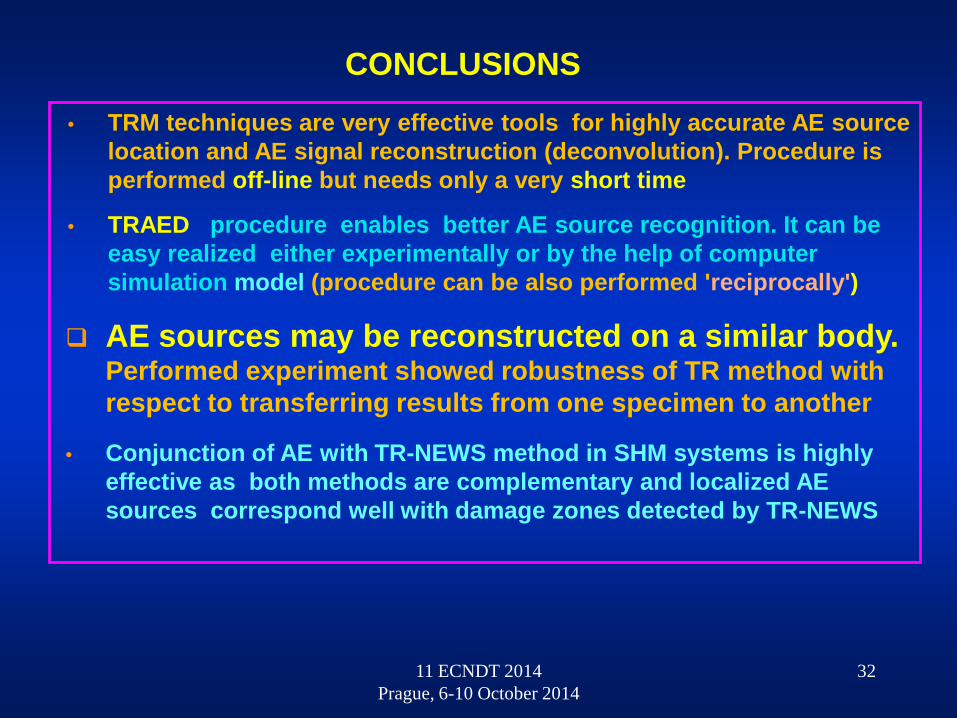
• TRM techniques are very effective tools for highly accurate AE source location and AE signal reconstruction (deconvolution). Procedure is performed off-line but needs only a very short time
• TRAED procedure enables better AE source recognition. It can be easy realized either experimentally or by the help of computer simulation model (procedure can be also performed 'reciprocally')
AE sources may be reconstructed on a similar body. Performed experiment showed robustness of TR method with respect to transferring results from one specimen to another
• Conjunction of AE with TR-NEWS method in SHM systems is highly effective as both methods are complementary and localized AE sources correspond well with damage zones detected by TR-NEWS
CONCLUSIONS
11 ECNDT 2014 Prague, 6-10 October 2014
32

THANK YOU
FOR YOUR KIND ATTENTION
11 ECNDT 2014 Prague, 6-10 October 2014
33


![SENTRO - Acoustic Emission Presentation [2016]](https://img.pdfslide.net/doc/110x75/5875c8511a28ab33128b6abf/sentro-acoustic-emission-presentation-2016.jpg)