Embed Size (px)
Citation preview
Time Synchronization
Keystone 2 Devices
1
2
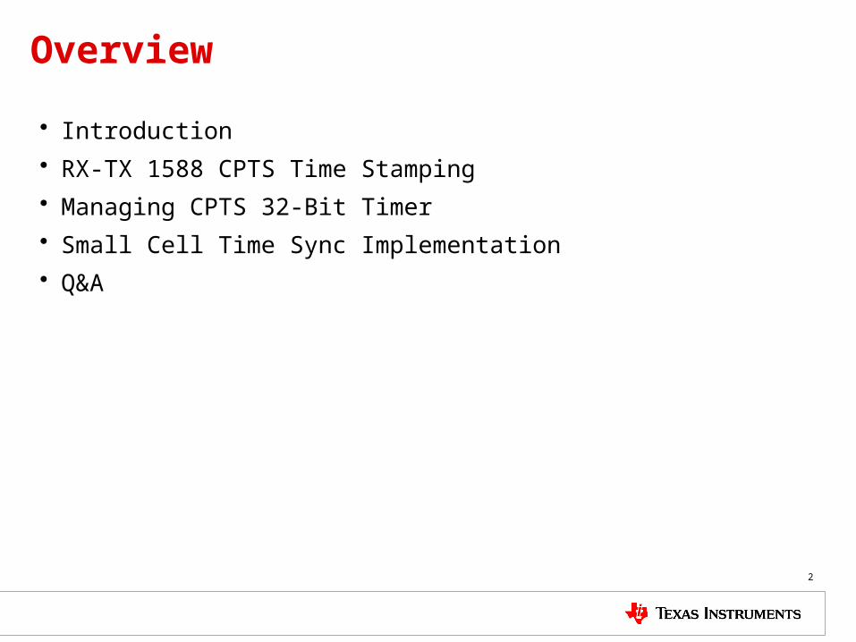
Overview
• Introduction
• RX-TX 1588 CPTS Time Stamping
• Managing CPTS 32-Bit Timer
• Small Cell Time Sync Implementation
• Q&A
Introduction
4
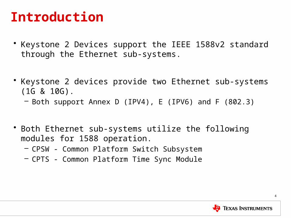
Introduction
• Keystone 2 Devices support the IEEE 1588v2 standard through the Ethernet sub-systems.
• Keystone 2 devices provide two Ethernet sub-systems (1G & 10G).– Both support Annex D (IPV4), E (IPV6) and F (802.3)
• Both Ethernet sub-systems utilize the following modules for 1588 operation.– CPSW - Common Platform Switch Subsystem– CPTS - Common Platform Time Sync Module
5
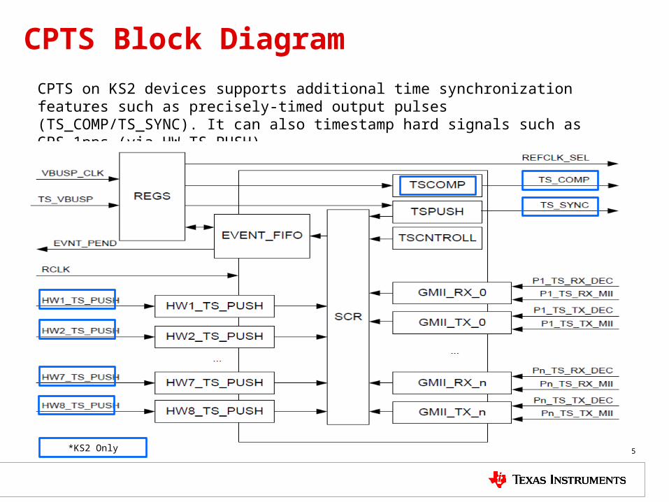
CPTS Block Diagram
CPTS on KS2 devices supports additional time synchronization features such as precisely-timed output pulses (TS_COMP/TS_SYNC). It can also timestamp hard signals such as GPS 1pps (via HW_TS_PUSH).
*KS2 Only
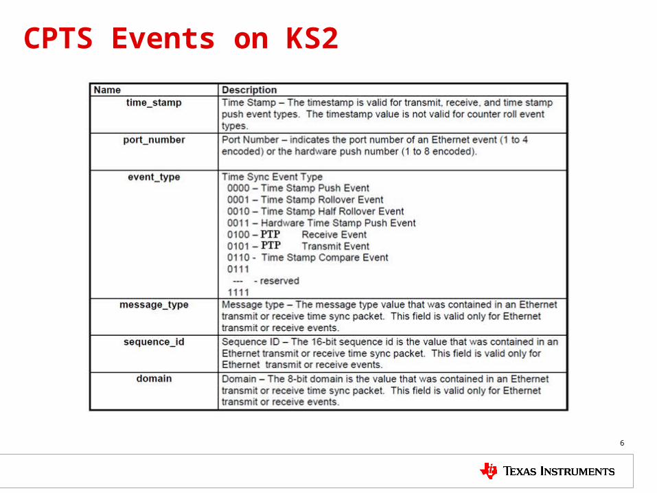
CPTS Events on KS2
6
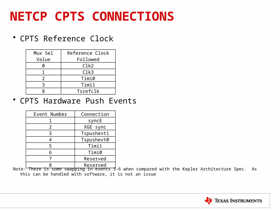
NETCP CPTS CONNECTIONS
• CPTS Reference Clock
• CPTS Hardware Push Events
Note- There is some swapping in events 3-6 when compared with the Kepler Architecture Spec. As this can be handled with software, it is not an issue
Mux Sel Value Reference Clock Followed
0 Clk21 Clk32 Timi03 Timi18 Tsrefclk
Event Number Connection1 syncE2 XGE sync3 Tspushevt14 Tspushevt05 Timi16 Timi07 Reserved8 Reserved
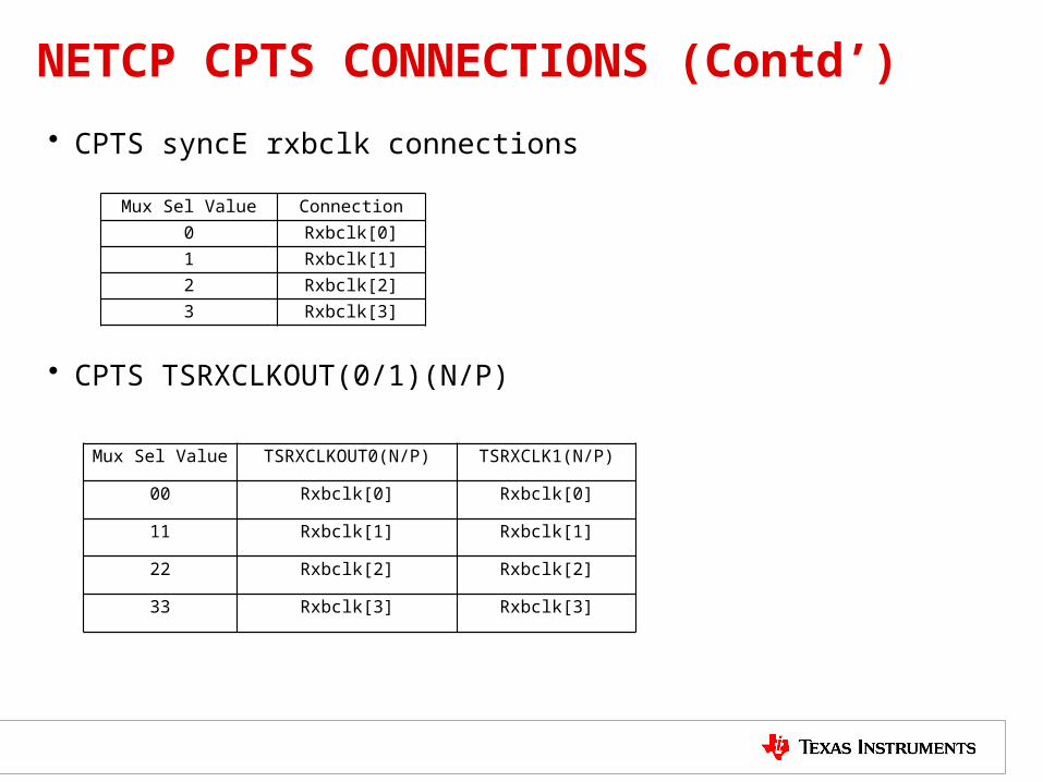
NETCP CPTS CONNECTIONS (Contd’)
• CPTS syncE rxbclk connections
• CPTS TSRXCLKOUT(0/1)(N/P)
Mux Sel Value Connection
0 Rxbclk[0]
1 Rxbclk[1]
2 Rxbclk[2]
3 Rxbclk[3]
Mux Sel Value TSRXCLKOUT0(N/P) TSRXCLK1(N/P)
00 Rxbclk[0] Rxbclk[0]
11 Rxbclk[1] Rxbclk[1]
22 Rxbclk[2] Rxbclk[2]
33 Rxbclk[3] Rxbclk[3]
RX-TX 1588 CPTS Time Stamping
9
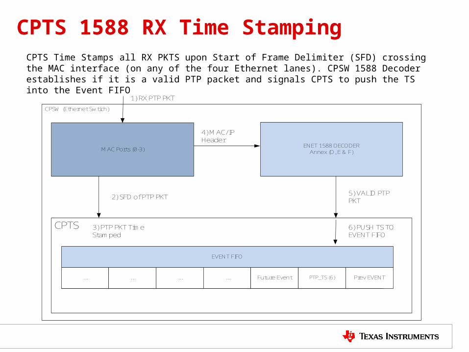
CPTS 1588 RX Time StampingCPTS Time Stamps all RX PKTS upon Start of Frame Delimiter (SFD) crossing the MAC interface (on any of the four Ethernet lanes). CPSW 1588 Decoder establishes if it is a valid PTP packet and signals CPTS to push the TS into the Event FIFO
EVENT FIFO
... ... ... ... Future Event PTP_TS (6) Prev EVENT
CPTS
ENET 1588 DECODERAnnex (D, E & F)MAC Ports (0-3)
1) RX PTP PKT
2) SFD of PTP PKT
4) MAC/IP Header
6) PUSH TS TO EVENT FIFO
5) VALID PTP PKT
3) PTP PKT Time Stamped
CPSW (Ethernet Swtich)
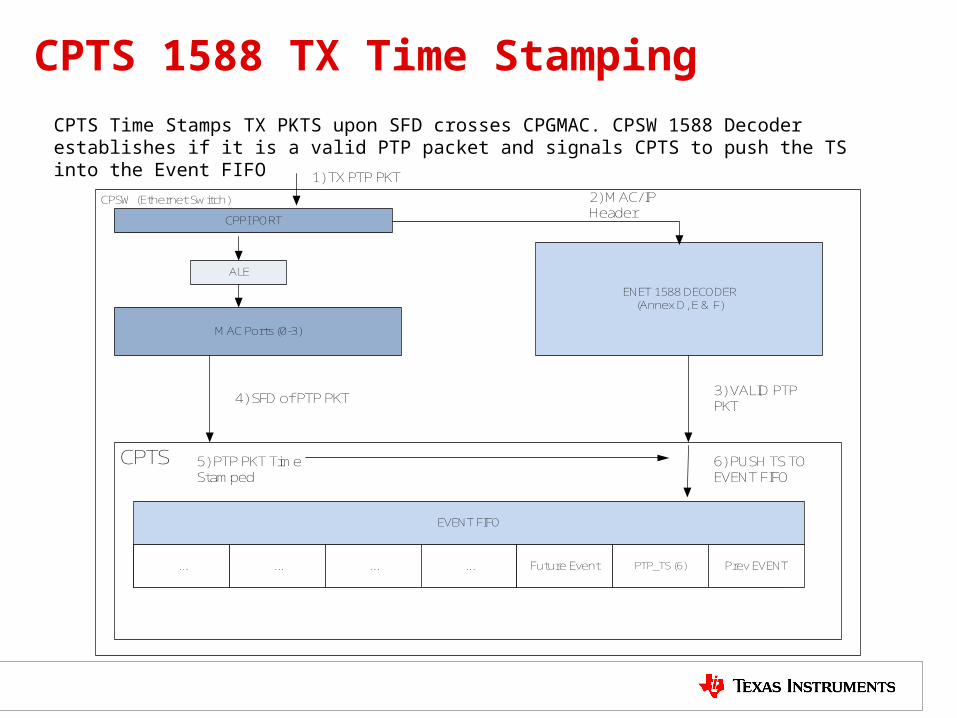
CPTS 1588 TX Time Stamping
CPTS Time Stamps TX PKTS upon SFD crosses CPGMAC. CPSW 1588 Decoder establishes if it is a valid PTP packet and signals CPTS to push the TS into the Event FIFO
EVENT FIFO
... ... ... ... Future Event PTP_TS (6) Prev EVENT
CPTS
ENET 1588 DECODER(Annex D, E & F)
MAC Ports (0-3)
1) TX PTP PKT
4) SFD of PTP PKT
2) MAC/IP Header
6) PUSH TS TO EVENT FIFO
3) VALID PTP PKT
5) PTP PKT Time Stamped
CPPI PORT
ALE
CPSW (Ethernet Switch)
Managing CPTS 32-Bit Timer
12
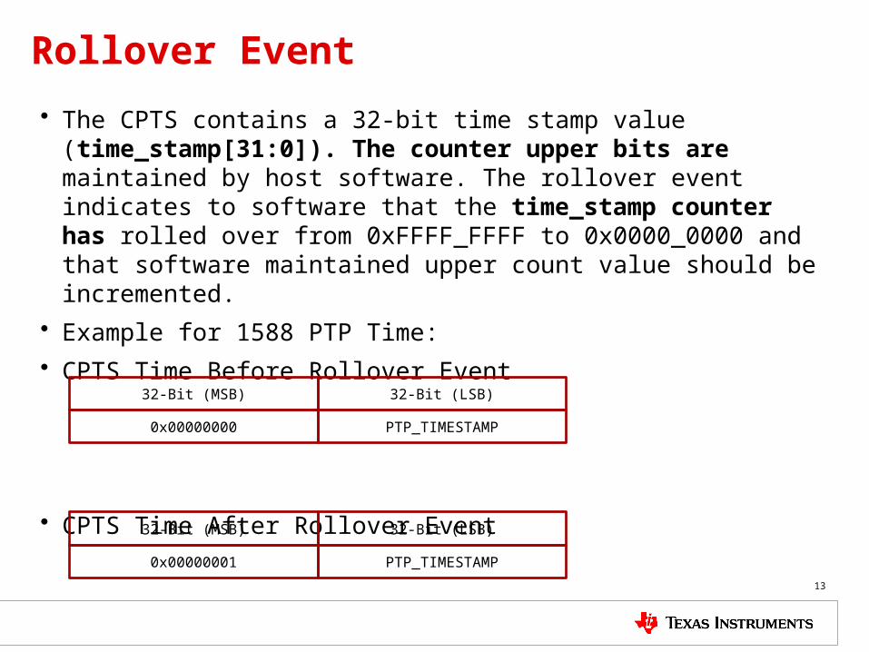
Rollover Event
• The CPTS contains a 32-bit time stamp value (time_stamp[31:0]). The counter upper bits are maintained by host software. The rollover event indicates to software that the time_stamp counter has rolled over from 0xFFFF_FFFF to 0x0000_0000 and that software maintained upper count value should be incremented.
• Example for 1588 PTP Time:
• CPTS Time Before Rollover Event
• CPTS Time After Rollover Event
13
32-Bit (MSB) 32-Bit (LSB)
0x00000001 PTP_TIMESTAMP
32-Bit (MSB) 32-Bit (LSB)
0x00000000 PTP_TIMESTAMP
Half-Rollover Event
• As the 1588 decoder takes some time to validate a packet it can happen that a PTP packet is timestamped just before a rollover event, but the rollover event is pushed into the EVENT FIFO first.
• The Half-Rollover event indicates to software that the time_stamp counter has rolled over from 0x7FFF_FFFF to 0x8000_0000.
• This allows the software to determine after a rollover event if the following PTP_TS happened after or before the rollover.
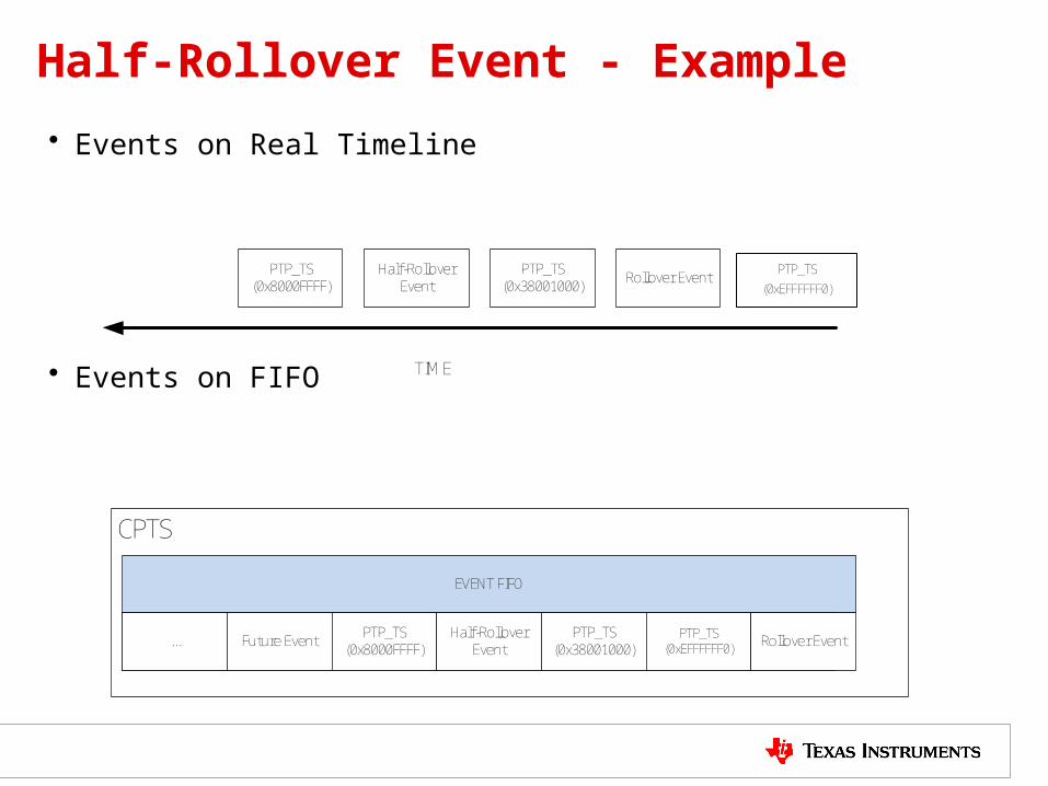
Half-Rollover Event - Example
• Events on Real Timeline
• Events on FIFO TIME
PTP_TS (0xEFFFFFF0)
Rollover EventPTP_TS(0x38001000)
Half-Rollover Event
PTP_TS(0x8000FFFF)
EVENT FIFO
... Future Event PTP_TS(0x8000FFFF)
Half-Rollover Event
PTP_TS(0x38001000)
PTP_TS (0xEFFFFFF0) Rollover Event
CPTS
Half-Rollover Event - Example
• To solve this issue software checks the MSB of the PTP_TS between a rollover event and a half-rollover event. – If it is 1, it happened before the rollover event. Thus the upper 32-bit CPTS time
needs to be decremented for this timestamp. – If it is 0 it happened after the rollover event.
Linux System Time and CPTS Time
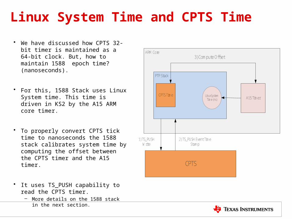
• We have discussed how CPTS 32-bit timer is maintained as a 64-bit clock. But, how to maintain 1588 epoch time? (nanoseconds).
• For this, 1588 Stack uses Linux System time. This time is driven in KS2 by the A15 ARM core timer.
• To properly convert CPTS tick time to nanoseconds the 1588 stack calibrates system time by computing the offset between the CPTS timer and the A15 timer.
• It uses TS_PUSH capability to read the CPTS timer.
– More details on the 1588 stack in the next section.
ARM Core
CPTS
PTP Stack
A15 Timer
2) TS_PUSH Event Time Stamp
CPTS Time LinuxSystem Time (ns)
1) TS_PUSH Write
3) Compute Offset

Small Cell Time Sync Implementation
18
IEEE 1588 Overview on Keystone 2
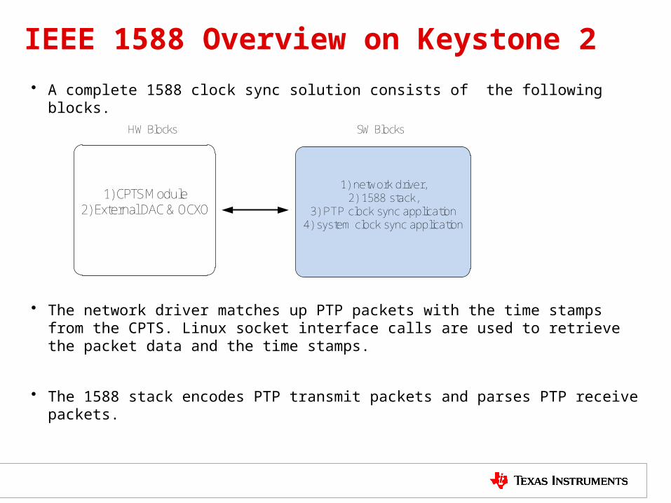
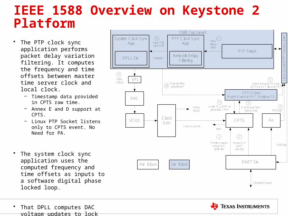
• A complete 1588 clock sync solution consists of the following blocks.
• The network driver matches up PTP packets with the time stamps from the CPTS. Linux socket interface calls are used to retrieve the packet data and the time stamps.
• The 1588 stack encodes PTP transmit packets and parses PTP receive packets.
1) CPTS Module2) External DAC & OCXO
1) network driver, 2) 1588 stack,
3) PTP clock sync application 4) system clock sync application
HW Blocks SW Blocks
IEEE 1588 Overview on Keystone 2 Platform
• The PTP clock sync application performs packet delay variation filtering. It computes the frequency and time offsets between master time server clock and local clock.
– Timestamp data provided in CPTS raw time.
– Annex E and D support at CPTS.– Linux PTP Socket listens only to
CPTS event. No Need for PA.
• The system clock sync application uses the computed frequency and time offsets as inputs to a software digital phase locked loop.
• That DPLL computes DAC voltage updates to lock the VCXO frequency to the master time server
– SPI write done by ARM. – No DSP needed.
1588 Top Level
ENET SW
Ethernet Packet
Pkt time stamp every SOF delimiter
Annex D, E and F
decode
Pkt Data
CPTS
1 2
PA
Lin
ux
So
cke
t P
TP
Pa
cke
t Lis
ten
Events and Time stamp Data
4
Pkt Data
3
PTP Stack
PTP Clock Sync App
Time stamp data
7
Freq. OffsTime Offs
8
Network Delay Filtering
System Clock Sync App
DPLL SW Statistics
DAC
VCXOClock Gen
TSREFCLKP/N
Other clocks
Write TS_COMP to generate 1 PPS
Freq. Adjust
9
10
HW Block SW Block
1pps
SPIForward freq adjustment
CPTS DriverMatch Event to PKT, Retrieve TS
11
Add Event and TS Data [CPTS & UCT time] to PKT
5
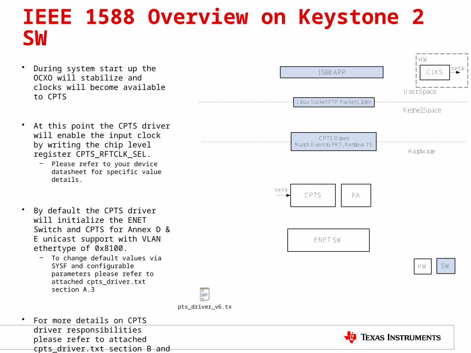
IEEE 1588 Overview on Keystone 2 SW
• During system start up the OCXO will stabilize and clocks will become available to CPTS
• At this point the CPTS driver will enable the input clock by writing the chip level register CPTS_RFTCLK_SEL.
– Please refer to your device datasheet for specific value details.
• By default the CPTS driver will initialize the ENET Switch and CPTS for Annex D & E unicast support with VLAN ethertype of 0x8100.
– To change default values via SYSF and configurable parameters please refer to attached cpts_driver.txt section A.3
• For more details on CPTS driver responsibilities please refer to attached cpts_driver.txt section B and go to http://processors.wiki.ti.com/index.php/MCSDK_UG_Chapter_Exploring#Common_Platform_Time_Sync_.28CPTS.29
1588 APP
ENET SW
CPTS PA
Linux Socket PTP Packet Listen
HW SW
CPTS DriverMatch Event to PKT, Retrieve TS
User Space
Kernel Space
Hardware
CLKS
HWtsrefclk
tsrefclk
cpts_driver_v6.txt
IEEE 1588 Overview on Keystone 2 SW
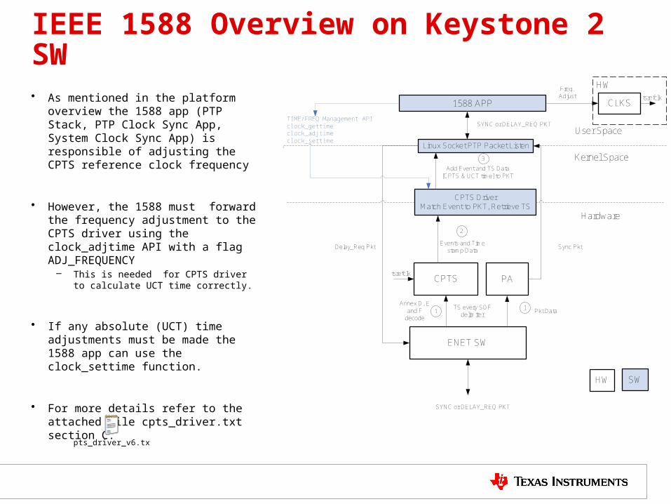
• As mentioned in the platform overview the 1588 app (PTP Stack, PTP Clock Sync App, System Clock Sync App) is responsible of adjusting the CPTS reference clock frequency
• However, the 1588 must forward the frequency adjustment to the CPTS driver using the clock_adjtime API with a flag ADJ_FREQUENCY
– This is needed for CPTS driver to calculate UCT time correctly.
• If any absolute (UCT) time adjustments must be made the 1588 app can use the clock_settime function.
• For more details refer to the attached file cpts_driver.txt section C.
1588 APP
ENET SW
SYNC or DELAY_REQ PKT
TS every SOF delimiter
Annex D, E and F
decodePkt Data
CPTS
1
PA
Linux Socket PTP Packet Listen
Events and Time stamp Data
Sync Pkt
HW SW
CPTS DriverMatch Event to PKT, Retrieve TS
Add Event and TS Data [CPTS & UCT time] to PKT
User Space
Kernel Space
Hardware
1
2
3
Delay_Req Pkt
SYNC or DELAY_REQ PKTTIME/FREQ Management APIclock_gettime clock_adjtime clock_settime
tsrefclk
CLKS
HWtsrefclk
Freq. Adjust
cpts_driver_v6.txt
IEEE 1588 DPLL Software
• Once the clock sync app calibrates CPTS clock it can program CPTS to generate the 1pps to AIF. However, the master Sync packets can be lost for a period of time. – When this happens the local clock can drift from the master time.– DPLL software needs to determine if it needs re-synchronization.
• Along with the DPLL SW the Clock Sync App needs a state machine to 1. perform initial synchronization,
2. generate output pulse,
3. keep frequency and time locked to master time,
4. hold frequency during master signal loss,
5. Re-establish synchronization upon signal return.
• In the next few slides the state machine and DPLL algorithm will be explained.
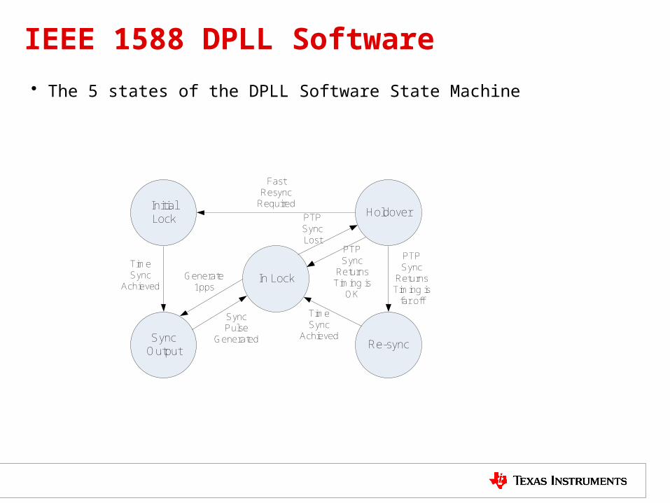
IEEE 1588 DPLL Software
• The 5 states of the DPLL Software State Machine
In Lock
Holdover
Re-sync
Initial Lock
Sync Output
Time Sync
Achieved
Sync Pulse
Generated
PTP Sync Lost
PTP Sync
ReturnsTiming is
far offTime Sync
Achieved
Fast Resync
Required
PTP Sync
ReturnsTiming is
OK
Generate 1pps
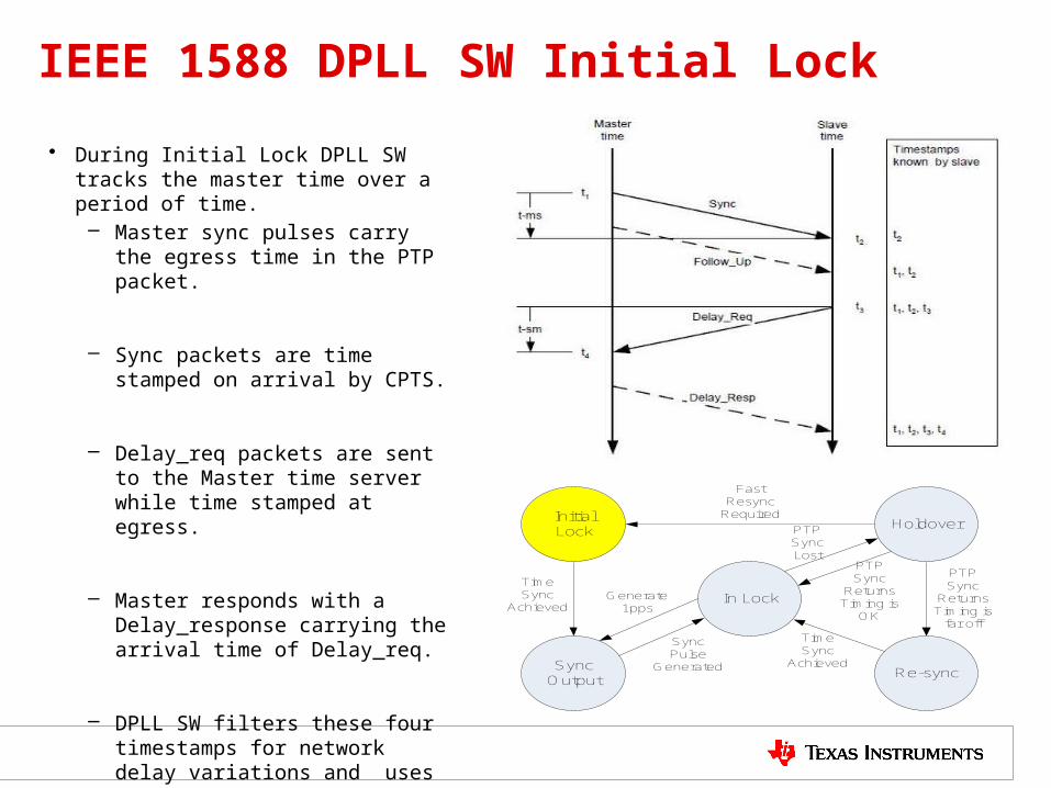
IEEE 1588 DPLL SW Initial Lock
• During Initial Lock DPLL SW tracks the master time over a period of time.– Master sync pulses carry the egress
time in the PTP packet.
– Sync packets are time stamped on arrival by CPTS.
– Delay_req packets are sent to the Master time server while time stamped at egress.
– Master responds with a Delay_response carrying the arrival time of Delay_req.
– DPLL SW filters these four timestamps for network delay variations and uses them as inputs to output a control voltage step to the DAC through the SPI interface.
In Lock
Holdover
Re-sync
Initial Lock
Sync Output
Time Sync
Achieved
Sync Pulse
Generated
PTP Sync Lost
PTP Sync
ReturnsTiming is
far offTime Sync
Achieved
Fast Resync
Required
PTP Sync
ReturnsTiming is
OK
Generate 1pps
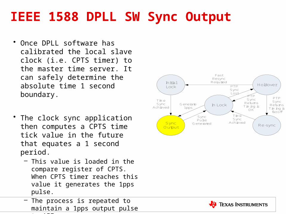
IEEE 1588 DPLL SW Sync Output
• Once DPLL software has calibrated the local slave clock (i.e. CPTS timer) to the master time server. It can safely determine the absolute time 1 second boundary.
• The clock sync application then computes a CPTS time tick value in the future that equates a 1 second period.– This value is loaded in the compare
register of CPTS. When CPTS timer reaches this value it generates the 1pps pulse.
– The process is repeated to maintain a 1pps output pulse to AIF.
In Lock
Holdover
Re-sync
Initial Lock
Sync Output
Time Sync
Achieved
Sync Pulse
Generated
PTP Sync Lost
PTP Sync
ReturnsTiming is
far offTime Sync
Achieved
Fast Resync
Required
PTP Sync
ReturnsTiming is
OK
Generate 1pps
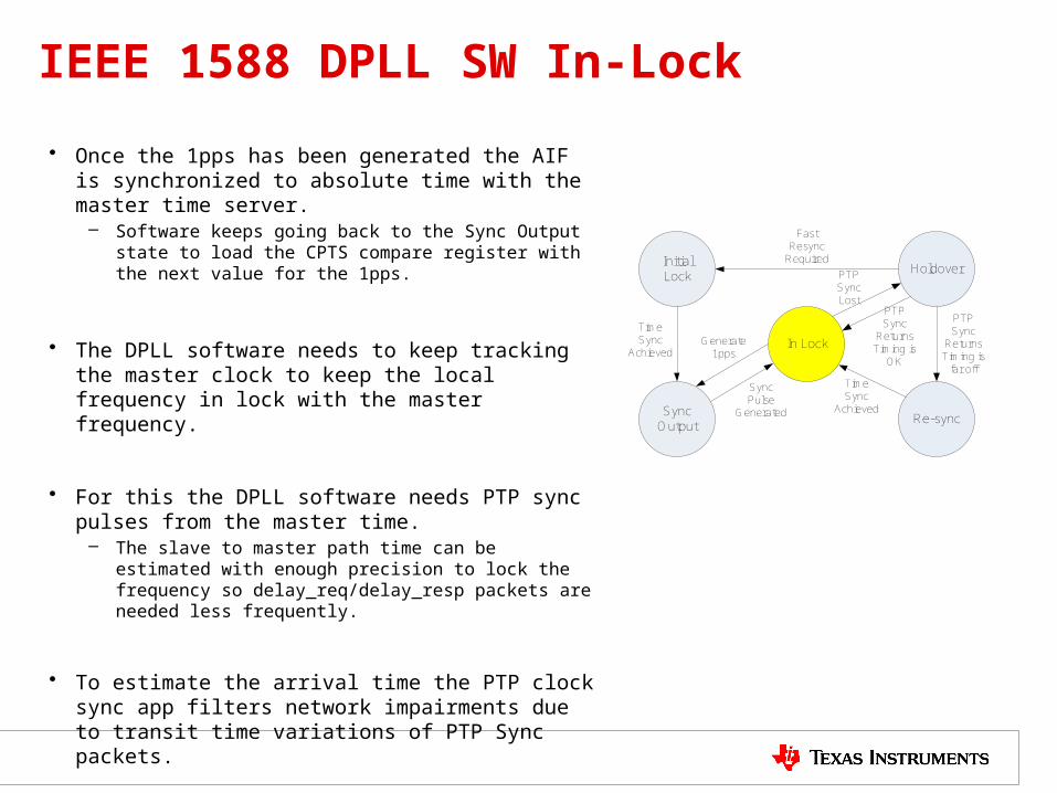
IEEE 1588 DPLL SW In-Lock
• Once the 1pps has been generated the AIF is synchronized to absolute time with the master time server.
– Software keeps going back to the Sync Output state to load the CPTS compare register with the next value for the 1pps.
• The DPLL software needs to keep tracking the master clock to keep the local frequency in lock with the master frequency.
• For this the DPLL software needs PTP sync pulses from the master time.
– The slave to master path time can be estimated with enough precision to lock the frequency so delay_req/delay_resp packets are needed less frequently.
• To estimate the arrival time the PTP clock sync app filters network impairments due to transit time variations of PTP Sync packets.
In Lock
Holdover
Re-sync
Initial Lock
Sync Output
Time Sync
Achieved
Sync Pulse
Generated
PTP Sync Lost
PTP Sync
ReturnsTiming is
far offTime Sync
Achieved
Fast Resync
Required
PTP Sync
ReturnsTiming is
OK
Generate 1pps
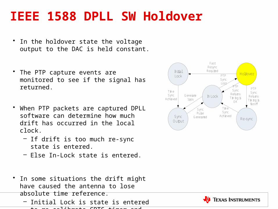
IEEE 1588 DPLL SW Holdover
• In the holdover state the voltage output to the DAC is held constant.
• The PTP capture events are monitored to see if the signal has returned.
• When PTP packets are captured DPLL software can determine how much drift has occurred in the local clock.– If drift is too much re-sync state is entered. – Else In-Lock state is entered.
• In some situations the drift might have caused the antenna to lose absolute time reference. – Initial Lock is state is entered to re-calibrate
CPTS timer and generate another sync pulse to the AIF.
In Lock
Holdover
Re-sync
Initial Lock
Sync Output
Time Sync
Achieved
Sync Pulse
Generated
PTP Sync Lost
PTP Sync
ReturnsTiming is
far offTime Sync
Achieved
Fast Resync
Required
PTP Sync
ReturnsTiming is
OK
Generate 1pps
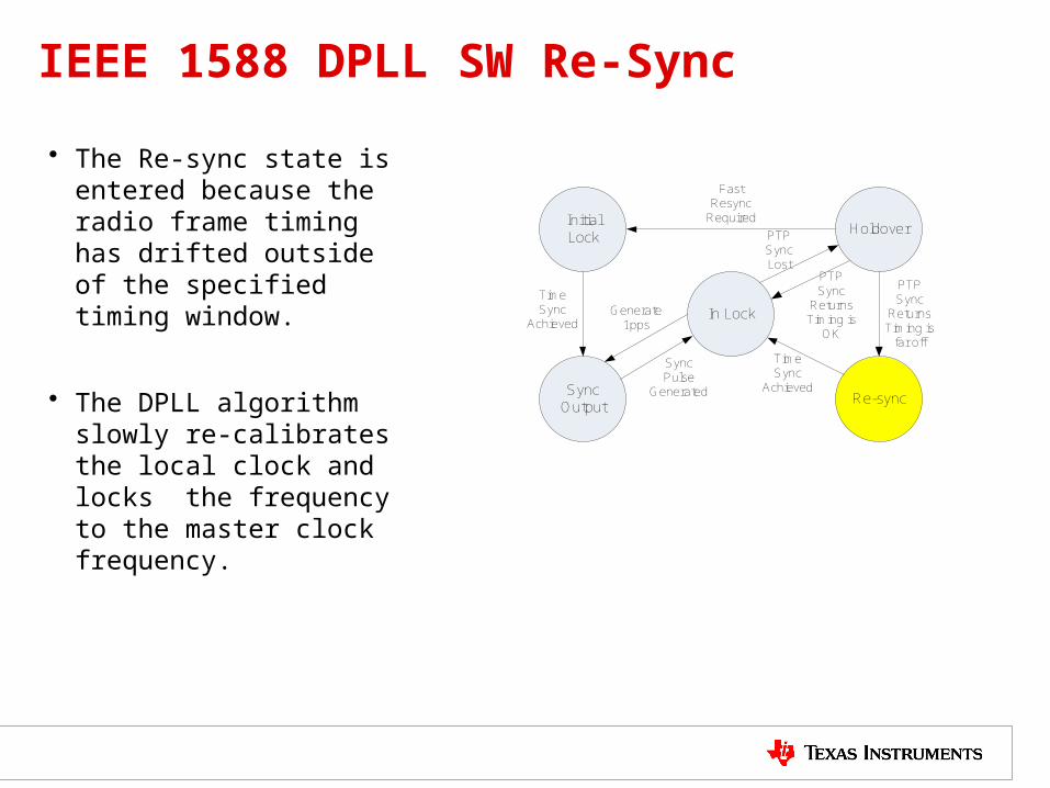
IEEE 1588 DPLL SW Re-Sync
• The Re-sync state is entered because the radio frame timing has drifted outside of the specified timing window.
• The DPLL algorithm slowly re-calibrates the local clock and locks the frequency to the master clock frequency.
In Lock
Holdover
Re-sync
Initial Lock
Sync Output
Time Sync
Achieved
Sync Pulse
Generated
PTP Sync Lost
PTP Sync
ReturnsTiming is
far offTime Sync
Achieved
Fast Resync
Required
PTP Sync
ReturnsTiming is
OK
Generate 1pps
GPS Time Sync
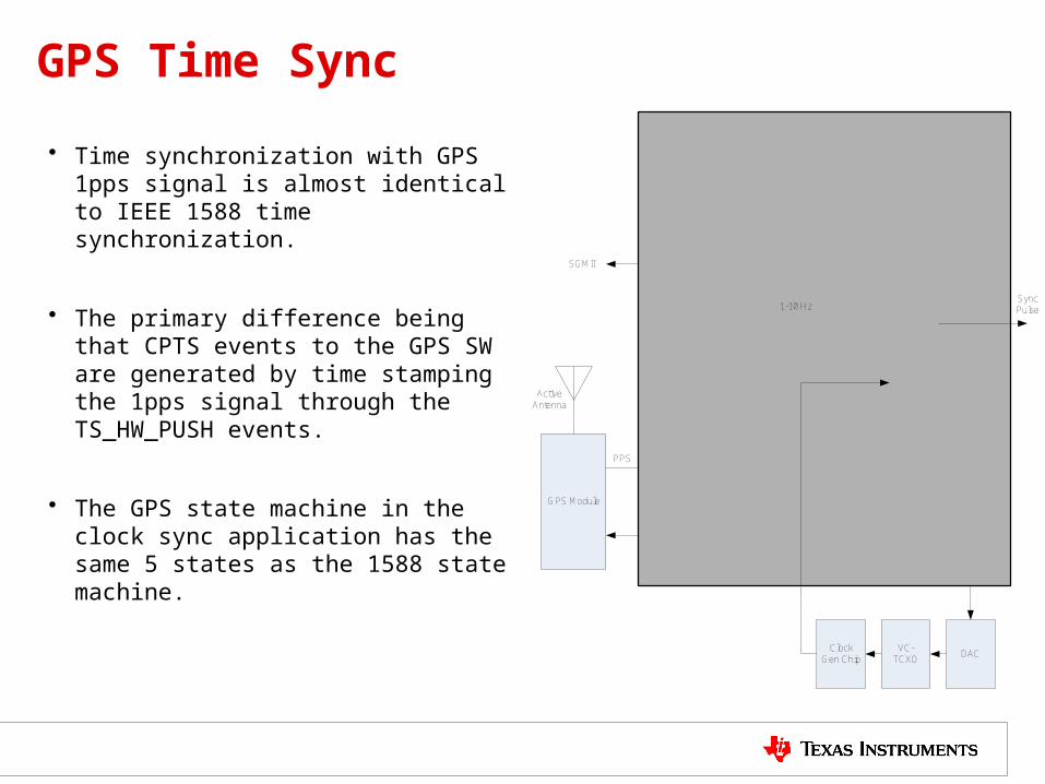
• Time synchronization with GPS 1pps signal is almost identical to IEEE 1588 time synchronization.
• The primary difference being that CPTS events to the GPS SW are generated by time stamping the 1pps signal through the TS_HW_PUSH events.
• The GPS state machine in the clock sync application has the same 5 states as the 1588 state machine.
Clock Gen Chip
DAC
DPLLSoftware
GPS Module
CPTS 1.3
Packet Accelerator
Clock Recovery
Ethernet PHY
Programmed Divider
SGMII
Active Antenna
HW Pulse 1
Ethernet Packets
HW Pulse 2
Sync Packets
UART
Ref CLK
1588 Stack
VC-TCXO
GPS SW
SPI
Sync Pulse1-10 Hz
PPS


![IEEE 1588/PTP: The Future of Time Synchronization in the Electric Power … · 2013. 4. 12. · With the Precision Time Protocol, the IEEE 1588 standard [3] defines a solution for](https://img.pdfslide.net/doc/110x75/6122dbd4f278286e344ec3f4/ieee-1588ptp-the-future-of-time-synchronization-in-the-electric-power-2013-4.jpg)