Embed Size (px)
Citation preview

TIME MAINTENANCE OF USER CLOCKS VIA THE TRACKING AND DATA RELAY SATELLITE SYSTEM
Gary Whitworth, J. W. McIntyre, and R. E. Downs The Johns Hopkins University Applied Physics Laboratory
Laurel, Maryland
ABSTRACT
During the 1980fs, all NASA-supported low earth orbital spacecraft will be supported by the Tracking Data and Relay Satellite System (TDRSS). User spacecraft will have the capability of time-tagging science and house- keeping data on board the spacecraft. This activity requires that the on-board time scale be relatable to a standard time scale such as Universal Time Coordinated (UTC). A system is described which uses the TDRSS itself to compare the user satellite clock with a clock at the White Sands station that is referenced to UTC. No command of the spacecraft by the system is required, and actual on-board clock corrections are made by the spacecraft control center at its discretion.
Computer models were constructed using basic orbital parameters for user and TDRS satellites. With only first-order corrections and simple averaging techniques for constant clock rates, error measurement precision of better than one microsecond was obtained. More sophis- ticated computations should allow considerable improve- ment over this.
NASA supported spacecraft in the future will require on board time tagging and operational timing requirements in the microsecond and sub- microsecond range. Such precision is not achievable using ground based clocks. It can only be obtained by having high quality clocks on board the spacecraft and a means of closely maintaining the spacecraft time scale to a universal standard such as UTC. These spacecraft will be supported by NASA's Tracking and Data Relay Satellite System (TDRSS), which is scheduled to become operational in 1984.
This paper describes a proposed system for high precision main- tenance of user spacecraft clocks which is planned to be a service of the TDRSS. Detailed descriptions have been given in an earlier report (1). This timing system determines coarse and fine spacecraft clock error with
Report Documentation Page Form ApprovedOMB No. 0704-0188
Public reporting burden for the collection of information is estimated to average 1 hour per response, including the time for reviewing instructions, searching existing data sources, gathering andmaintaining the data needed, and completing and reviewing the collection of information. Send comments regarding this burden estimate or any other aspect of this collection of information,including suggestions for reducing this burden, to Washington Headquarters Services, Directorate for Information Operations and Reports, 1215 Jefferson Davis Highway, Suite 1204, ArlingtonVA 22202-4302. Respondents should be aware that notwithstanding any other provision of law, no person shall be subject to a penalty for failing to comply with a collection of information if itdoes not display a currently valid OMB control number.
1. REPORT DATE DEC 1982 2. REPORT TYPE
3. DATES COVERED 00-00-1982 to 00-00-1982
4. TITLE AND SUBTITLE Time Maintenance of User Clocks via the Tracking and Data RelaySatellite System
5a. CONTRACT NUMBER
5b. GRANT NUMBER
5c. PROGRAM ELEMENT NUMBER
6. AUTHOR(S) 5d. PROJECT NUMBER
5e. TASK NUMBER
5f. WORK UNIT NUMBER
7. PERFORMING ORGANIZATION NAME(S) AND ADDRESS(ES) The Johns Hopkins University,Applied Physics Laboratory,Laurel,MD,20723
8. PERFORMING ORGANIZATIONREPORT NUMBER
9. SPONSORING/MONITORING AGENCY NAME(S) AND ADDRESS(ES) 10. SPONSOR/MONITOR’S ACRONYM(S)
11. SPONSOR/MONITOR’S REPORT NUMBER(S)
12. DISTRIBUTION/AVAILABILITY STATEMENT Approved for public release; distribution unlimited
13. SUPPLEMENTARY NOTES Proceedings of the Fourteenth Annual Precise Time and Time Interval (PTTI) Applications and PlanningMeeting, Greenbelt, MD, 30 Nov - 2 Dec 1982
14. ABSTRACT see report
15. SUBJECT TERMS
16. SECURITY CLASSIFICATION OF: 17. LIMITATION OF ABSTRACT Same as
Report (SAR)
18. NUMBEROF PAGES
18
19a. NAME OFRESPONSIBLE PERSON
a. REPORT unclassified
b. ABSTRACT unclassified
c. THIS PAGE unclassified
Standard Form 298 (Rev. 8-98) Prescribed by ANSI Std Z39-18

respect to UTC. Coarse error is determined from the spacecraft clock time code to one second resolution. Fine error is defined as the error in the once per second clock "tick."
To begin, a brief description of the TDRSS and its communications link to user satellites is in order. Figure 1 shows the basic geometry of the TDRS system. Here the communications paths between the single ground station at White Sands New Mexico and a low earth orbital user spacecraft via the geosynchronous Tracking and Data Relay (TDR) satellite are shown. The TDR satellite is transparent to data between ground station and user spacecraft. The command link to the user spacecraft is referred to as the "forwardt' link. Spacecraft telemetry returns to the ground station via the "return" link.
Three main elements make up the TDRS communications system, shown in Figure 2. A user spacecraft is commanded by and returns telemetry to a Project Operations Control Center (POCC), which is located remotely from the White Sands station. Command and telemetry data streams between the POCC and the TDRS ground station are carried over NASCOM (NASA Communi- cations) circuits which may involve any of several private and commercial communications paths including communications satellites. (The resulting unpredictability of time delay renders virtually impossible the precise monitoring of a user spacecraft clock from the POCC.)
As the forward (command) and return (telemetry) data streams enter and depart the White Sands station, they are monitored for quality. Capability exists for passively and noninterruptively monitoring the data flow between any and all of the user POCCts and spacecraft.
The TDRS ground terminal accepts command data as it enters from a POCC, modulates it on an S- or Ku-bank RF link, and transmits it to the user spacecraft via the TDR satellite. Likewise, telemetry returned from the spacecraft via the TDR satellite is demodulated and routed to the POCC .
A prime function of the TDRS system is to measure the radio range of the user spacecraft from the White Sands station via the TDR satellite. This is done by means of a pseudo-random noise (PRN) code which is modu- lated on the forward RF link along with the command data. A t the user spacecraft, the third element of the communication system, the PRN code is received along with command data in a transponding receiver.
A second PRN code, exactly like that received from the ground in length and chip rate but different in bit pattern, is modulated on the return RF link along with telemetry by the user spacecraft transponder. The code epoch, i.e., the defined "starting" point of the return code, is made to occur either simultaneously or in very precisely controlled synchronism with the received code epoch.

When the return code is received at the White Sands station, the round trip delay and thereby an estimate of one-way range to the user spacecraft may be determined by measuring the delay between the forward and return link code epochs. Although ranging may not be performed continuously on a user spacecraft during support periods, the forward and return PRN codes will still be present.
In addition to a TDRS compatible transponder, a user spacecraft will have command and telemetry processing equipment. Also, since this dis- cussion assumes the presence of a relatively stable oscillator and clock on board the user spacecraft, these are included in Figure 2.
The ready-made PRN code provides the TDRSS with the built-in capa- bility for precise time monitoring of a user spacecraft. The high bit rate of these codes (bit period equal to approximately 325 nanoseconds) provide the wide frequency bandwidth required to observe small increments of time. The high autocorrelation function of the codes, performed by the ground and spacecraft receivers, provide the high signal-to-noise ratios required to make precise measurements.
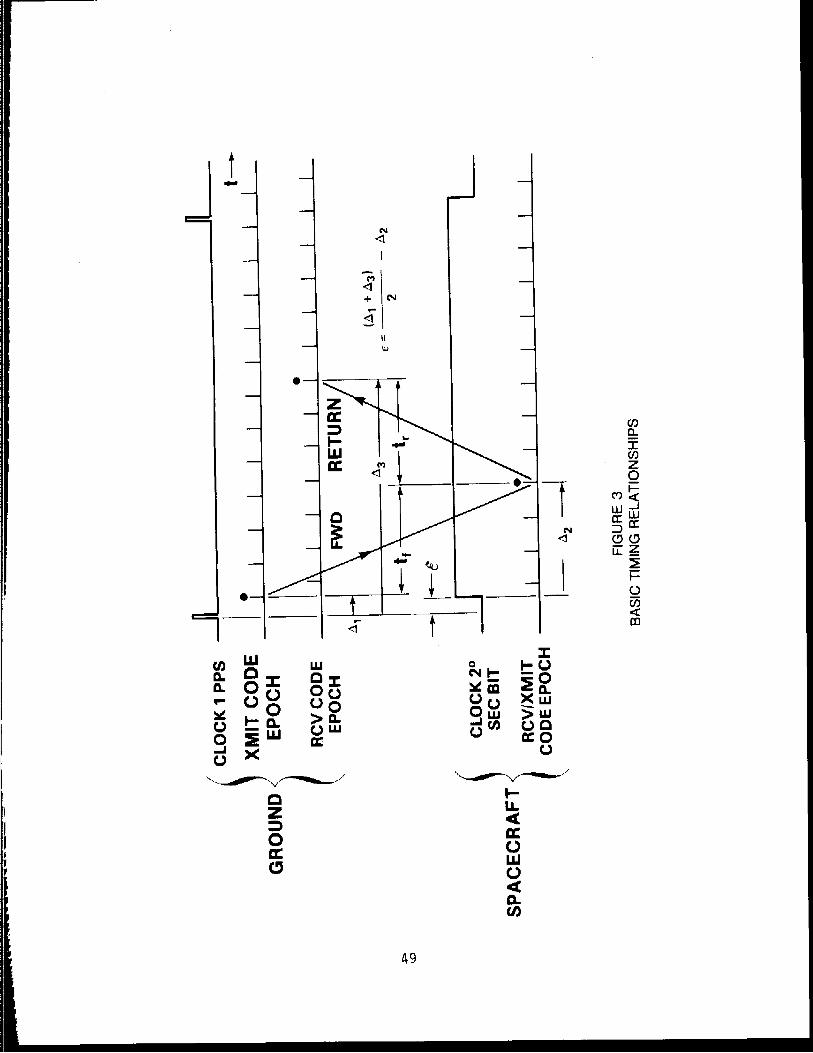
The basic time error calculation to be performed is that typical of all PRN time transfer systems. Figure 3 shows the timing relationships involved, in an oversimplified form. The ground clock once per second tick is indicated as the characteristic short pulse. The once per second mark of the user spacecraft clock, with error E , is shown as the transi- tion of the 2 O (i-e., unit) second bit in the spacecraft parallel time code. Measurements at both ground and spacecraft begin with a clock one second mark and end with a code epoch. Repeating code epochs are repre- sented by a series of short pulses, one PRN chip wide, The primary TDRSS code period is approximately 85 milliseconds.
The time interval between the ground clock one second tick and a particular code epoch, indicated by the dot, is measured as A . The dotted epoch propagates to the user spacecraft via the forwara link and its time of arrival measured as A . The coherently transponded code epoch is transported to the groung via the return link where its time of arrival is measured as A 3
To a first approximation, the forward path delay tf is equal to the return path delay tr. This approximation permits the slmplest clock fine error calculation to be

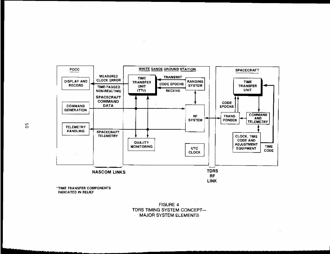
It can be seen that there must be timing system equipment on both the spacecraft and at the ground station in order to perform the measure- ments and calculations. This equipment fits into the existing TDRS communications system as shown in Figure 4. The minicomputer-controlled ground station Time Transfer Unit (TTU) will have access to the return telemetry stream by way of the data quality monitoring equipment. As with the latter equipment, the TTU only passively observes the data. It is particularly important to note that the TTU at no time interferes with or takes control of the command data.
To minimize the burden to the spacecraft, all mathematical manipula- tions are performed in the ground station TTU. The spacecraft TTU is required only to measured and perform certain other logic operations
2 necessary to compensate for real world complications not included in the simple model shown (such as how to identify the dotted epoch). Addition- ally, the spacecraft equipment must provide these measurements and logic results to the spacecraft telemetry system.
In addition to the telemetry data, the ground TTU also receives the ground station transmitted and received code epochs related to the space- craft whose clock is being monitored. These code epochs at this point are precision digital signals. The delays between the TDRS and TTU are precisely known to within a predictable tolerance within the TTU. The TTU uses these epochs to ultimately determine A and 4 1 3 '
The ground TTU then unravels the practical complications involved, corrects for known biases throughout the entire system, and determines the error between the spacecraft clock and the ground station clock which is maintained with respect to UTC. This operation can be performed as frequently as once per second. Averaging and curve fitting techniques are then used on a set of such data to refine the determination of clock error and clock error rates. Error prediction calculations can also be performed. This information is then time tagged and sent to the space- craft POCC over NASCOM lines by the TTU* At its discretion, the POCC may simply note the clock error or send corrective commands to the spacecraft immediately or at some future time.
We now examine the two TTU's in functional form. The ground station TTU, Figure 5, is under operational control of the Computer and Controller to which all hardware is connected by a standard data and control bus. A bus extender provides for communications with the POCC via NASCOM. The Telemetry and Command Monitor is able to monitor data of all spacecraft, which may vary widely in bit rate, frame length and format. Command data is monitored only to dbserve POCC commands for enabling the spacecraft TTU.
Gating and Counting Logic in the ground TTU controls both the time interval measurements and performs the necessary manipulations of timing

information in telemetry, to determine clock error. The Time Code Buffer supplies the ground station clock time code in proper format to the computer and controller for determining coarse time error.
The spacecraft TTU, shown in Figure 6.consists basically of Gating and Logic Circuitry and a holding register. The arrival of a received code epoch loads the holding register with the contents of a timing counter driven by the spacecraft clock. The contents of the holding register, which is reset to zero by the transition of the 2 O second bit of the spacecraft time code constitutes a measure of A 2 , and this is entered into the telemetry stream.
Note that t h e resolution of the A; measurement depends on the frequency of the spacecraft oscillator. As shown in Figure 6 the spacecraft time code has a resolution of only microseconds and thus is driven at 1/10 the oscillator frequency, while the A measurement reso- 2 lution is 0.1 microsecond. If the time code and h measurement resolu- 2 tions are the same, the timing counter could be eliminated and the time code read directly into the holding register.
It is necessary that the spacecraft time code for unit (2') seconds and above be entered into telemetry to monitor coarse time.
In general, the code epoch timing, telemetry data and frame rates, and the clock one second tick will be asynchronous. The timing system has been designed with this in mind, but this in no way precludes the use of synchronous timing aboard the spacecraft.
Also of course, the real world is not as simple as the pictures just discussed. One of the major complications is differential delay between return link code and telemetry data. This problem arises because refer- ence marks in the telemetry are used to identify the particular epoch (i-e., the dotted epoch of Figure 3) to which A2 was measured. Differ- ential delay occurs at the ground station due to delays in decoding the telemetry which has been convolutionally encoded on the spacecraft (a TDRSS requirement). This differential delay can confuse the ground TTU unless a sufficient number of logic cues are provided in the telemetry. Supplying these cues is the major function of the spacecraft Gating and Logic circuitry.
A second major complication is doppler frequency shift which necessitates modification of the basic propagation time calculation. It also alters the period of the PRN code, T , which i s important in the resolution of range ambiguity caused by tke s h o r t code length. These complications are all worked out by t h e ground based TTU.
Without exploring further the equipment or processing involved, t h e precision to be expected from this system is now considered. It is ex- pected that all TDRSS equipment and transmission delays will be known to

within a tolerance sufficient to meet the specified TDRSS ranging error of +50 nanoseconds. User spacecraft delays should be determined to equal tolerance. These uncertainties will result in systematic errors which will vary from one service interval to the next due to equipment switch- ing and spacecraft location.
Random errors will be caused primarily by RF system noise-induced jitter on the code epochs. This error, which will generally be filtered by the averaging of many measurements, is estimated to be a few percent of the code bit period of 325 nanoseconds.
The remaining errors are those caused by the degree of refinement of the measurements and calculations. To obtain information on the perform- ance to be expected, a computer simulation was performed. In this simu- lation, asynchronous counters were run to simulate ground and spacecraft clocks, code period, and telemetry frame rate. Also, delay parameters which mimic the differential delays were incorporated. Time interval measurements were made to one-quarter microsecond resolution. The posi- tions of the White Sands station, the TDR Satellite, and the user space- craft as a function of time were simulated by describing the satellite orbits with standard Kepler parameters in an earth centered inertial coordinate system. The ground station was modeled as a fixed point on a slightly oblate spheroid with a rotation period equal to one sidereal day,
Two sets of results of this simulation, which used only simple first order calculations to determine clock error are presented here. The first, Figure 7 shows the results when the user clock rate was set to zero, and the error estimate calculated by averaging a set of individual measurements over a 10 second interval (10 individual measurements). On the left are shown the results with no c0rrecti.m made for doppler shift for cases of user spacecraft approaching and retreating from the TDR satellite at maximum doppler shift, and for minimum doppler shift. The dot is the average error and the extremes are maximum excursions of individual measurements.
The results on the right are for the same conditions but with a simple first-order doppler correction added. The doppler correction was obtained from successive differences in the round trip range estimates (A - A ) Maximum deviations with doppler corrections are seen to be wi?hin A. 1 microseconds.
The second simulation result is shown in Figure 1. Here the user clock rate was set to a fixed rate with some initial error, and the capa- bility for error prediction examined. The simulation program gathered two small sets of individual error measurements separated by minutes or hours. A line fit to this data was made and the time error projected to 5 minutes past the last data point. Data are shown for relatively high

and low rates of the user clock. It may be seen that comparable results are obtained when more time is taken to determine the smaller rate.
The results indicate that the system will be able to predict short-term clock error to within one microsecond. With no measurement procedure changes, more sophisticated computations should permit even better performance.
Although the timing system is primarily intended to service earth orbital spacecraft, service to surface or airborne vehicles is also possible. Indeed time transfer to fixed locations using this system could provide precision comparable to results achieved in earlier ground-to-ground PRN timing experiments (2) , One such application is the maintenance of the ground station clock itself by links through the TDRSS with USNO or NBS.
This work was sponsored by NASA Goddard Space Flight Center.

REFERENCES
1. McIntyre, J.W., G . G. Whitworth, and R. E . Downs, Time Correc t ion For User S a t e l l i t e Clocks Via t h e Tracking and Data Relay S a t e l l i t e System, S3C-1-113 (SHU/APL), Feb. 1, 1982.
2. Chi, A.R. and E . Byron, Two Way Time Trans fe r Experiment Using a Synchronous S a t e l l i t e . Proceedings of t h e Seventh Annual P r e c i s e Time and Time In te rva l Planning Meeting, pp. 357-377.


POCC -- WHITE SANDS GROUND STATION - SPACECRAFT MEASURED
TlME TRANSMIT A
RANGING TRANSFER CODE EPOCHS SYSTEM TlME
RECORD TIME-TAGGED UNIT TRANSFER MON-REALTIME (TTU) UNIT
7
SPACECRAFT A A L COMMAND CODE
COMMAND DATA - EPOCHS GENERATION 1. 4 RF TRANS- COMMAND
SYSTEM j TELEMETRY
TELEMETRY HANDLING SPACECRAFT
TELEMETRY CLOCK, TlME CODE AND
MONtTORlNG EQUIPMENT CODE
P - NASCOM LINKS TDRS
RF LINK
TIME TRANSFER COMPONENTS INDICATED IN RELIEF
CLOCK El
FIGURE 4 TDRS TIMING SYSTEM CONCEPT-
MAJOR SYSTEM ELEMENTS

k t , z o > t o n - 5 + g g a
0


MICROSECONDS DEVIATION
MICROSECONDS DEVIATION

TRIAL I TRIAL 2
Ln CLOCK ERROR RATE $ MlCROSECONDlSECOND 0.1 NANOSECONDISECOND
P
INITIAL CLOCK ERROR 1 MICROSECOND -2.5 MICROSECOND
NO POINTS PER DATA SET 3 5
TIME BETWEEN DATA SETS 5 MINUTES ONE ORBIT
ERROR FOR 5 MINUTE PROJECTION 0.158 MlCROSECOND 0.273 MICROSECOND
TABLE 1 SIMULATION RESULTS SPACECRAFT CLUCK
MODELED WlTH CONSTANT DRIFT RATE (TWO DATA SET LINE FIT)

QUESTIONS AND ANSWERS
MR. PETER WOOD, Goddard Space F l i g h t Center
If one would make a comparison and t rade o f f between the GPS systems f o r t ime t r a n s f e r versus the TDRS, what a re the c r i t e r i o n s and how does your proposed system compare i n performance and o ther f a c t o r s ?
MR. GARY WHITWORTH, JHUIAPL
I ' m n o t sure I can comment d i r e c t l y on how they would compare i n per- formance when one o f t he major d i f f e rences would be expense o f course. The TDRS user has a l ready invested money i n a standard transponder, The t ime t r a n s f e r u n i t t h a t we've described here would probably be a very inexpensive op t i on on t h a t transponder. And e s s e n t i a l l y s ince t h i s i s a TDS se rv i ce i t would be e s s e n t i a l l y very small a d d i t i o n a l cos t t o t he user. I would t h i n k t h a t a t t h i s p o i n t t h a t performance w i t h the ref inement t h a t can take p lace i n the processing o f t he TDRS t i m i n g sys- tem, performance can be achieved t o be q u i t e comparable.
DR. WINKLER:
Two way, one way?
MR. GARY WHITWORTH:
Yes, t h i s i s a two-way system and as I ' v e pointed o u t before, i t can achieve t h a t type o f accuracy, c e r t a i n l y f o r f i x e d users, i n t h i s case i f compensated f o r proper ly , the o r b i t a l user can achieve that same accuracy.
DR. WINKLER:
I would 1 i ke t o ask you a quest ion concerning the l a s t $1 ide . On the l a s t s l i d e the comparison was between the two c locks, where the c lock which was 10,000 times b e t t e r a t the r a t e o f o n l y a t e n t h of a nano-
second per second, y e t f o r a 90 minute ca l i b r a t i o n i n t e r v a l you end up w i t h an e r r o r i n the p r e d i c t i o n tw i ce as l a r g e as the o the r one. Is t h a t ma in ly due t o g reater data r a t e on the f i r s t c lock?
MR. GARY WHITWORTH:
No, I t h i n k t h a t probably the answer t o t h a t i s t h a t you are us ing t o determine a very small break, i t i s very d i f f i c u l t t o do t o s t a r t w i th ; one needs t o --

DR. WINKLER:
Well t he c lock r a t e i s much smaller, a l r i g h t , bu t t he p r e d i c t i o n e r r o r ought t o be smal ler a l so commensurate I would guess. It i s somewhat paradoxical ly , t he r e s u l t , and I was wondering whether----
MR. GARY WHITWORTH:
Yes, t h i s has been po in ted o u t before. The on ly t h i n g I can say i n t h i s case t h a t t h i s i s a r e s u l t of very simple co r rec t i ons t o t h e a lgor i thms and I t h i n k fo r t h a t s o r t o f rate, probably one would need t o ex t rapo la te over several o r b i t s .
This i s j u s t a f i r s t c u t r e s u l t and we were shoot ing t o demonstrate one microsecond c a p a b i l i t y and we haven' t proceeded f u r t h e r than t h a t .

![F RELAY LOCATIONS [Cowl Side J/B LH Assembly Inner Circuit]myfirewood.com/TOYOTA/LAND_CRUISER/rm2660e/PDFs/...LAND CRUISER Station Wagon (EM2660E) 7.5A ACC ACC Relay IG1 NO.1 Relay](https://img.pdfslide.net/doc/110x75/60b9e5f70fb9a157c828543e/f-relay-locations-cowl-side-jb-lh-assembly-inner-circuit-land-cruiser-station.jpg)