Embed Size (px)
Citation preview
42 JUNE 2015 MotorAge.Com
Ô DRIVABILIT YÔ DRIVABILIT Y
Figure 1Ô ELECTRICAL
Photos: Bernie Thompson
As one goes through life, it is said that timing is everything. In the case of the internal com-bustion engine, this could not be truer. In order for the engine
to operate correctly, the event timing and event sequence must be correct. This means the location of the crank-shaft and camshaft positions must be
known, as well as their relationship to one another. So the physical position of the crankshaft and camshaft must be known.
In order to determine where in space these shafts’ physical positions are a sensor will be used. A sensor reads the physical quantity and con-verts this to an electrical signal. This
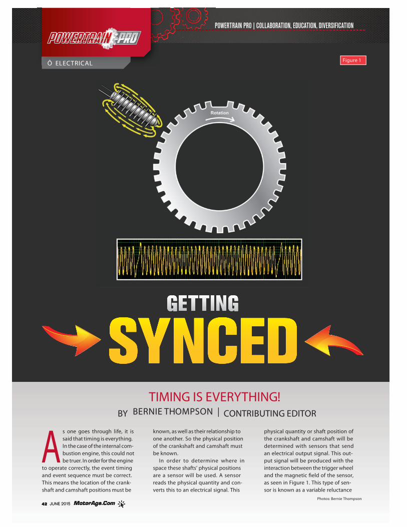
physical quantity or shaft position of the crankshaft and camshaft will be determined with sensors that send an electrical output signal. This out-put signal will be produced with the interaction between the trigger wheel and the magnetic �eld of the sensor, as seen in Figure 1. This type of sen-sor is known as a variable reluctance
TIMING IS EVERYTHING!BY BERNIE THOMPSON | CONTRIBUTING EDITOR
44 JUNE 2015 MotorAge.Com
POWERTRAIN PRO ELECTRICAL
sensor, but sensors that rectify this analog voltage will also be used; recti�cation of an analog signal means that it is converted to a digital signal or square wave. The trigger wheel is mounted on the shaft and will have some type of indexing means, such as a missing tooth, so the shaft’s orientation can be calculated. If the engine is rotating, the interaction between the trigger wheel and sensor will pro-duce a waveform or a voltage that changes over time.
The internal clockThe voltage change produced from a sensor is just that, a volt-age change. In order for the Engine Control Module (ECM) to be able to interpret the voltage change, a program must be written. The ECM microprocessor uses an internal clock to run with the software so that the shaft’s position can be calculated. This clock produces pulses that set up the rate at which tasks can be carried out. Each clock pulse sets up a machine cycle that caches the registers that carry out the pro-gramming tasks. Clock speed refers to the number of pulses per second generated by an oscillator that sets the tempo for the processor. Clock speed in the automotive computer is usu-ally measured in megahertz (MHz), or millions of pulses per second. In order for the microprocessor to work accurately, the clock will need to have a high oscillator stability, so a quartz crystal oscillator circuit is used.
The quartz crystal used in a quartz crystal oscillator cir-cuit is a thin, small piece of cut quartz. At the ends of the cut quartz, the surfaces are metallized in order to attach elec-trical connections. When producing the quartz crystal, the size and thickness are important because it a�ects the fun-damental frequency of oscillations. Once the quartz crystal is cut and shaped, the crystal cannot be used at any other frequency. In other words, its size and shape produce an oscillation frequency that is directly proportional to it size.
When a voltage source is applied to the quartz crystal, it begins to change shape, producing a characteristic known as the Piezoelectric E�ect. This Piezoelectric E�ect is the property of a crystal by which an electrical charge produces a mechanical force by changing the shape of the crystal and vice versa; a mechanical force applied to the crystal produces an electrical charge. This Piezoelectric E�ect pro-duces mechanical vibrations or oscillations that will directly change the voltage. It will be necessary to maintain a very accurate constant supply voltage on the quartz crystal so that the frequency output is maintained. This quartz clock circuit will send a continuous stream of square waves that will set the master clock and system timing within the microprocessor.
This master clock is built into the hardware of the micro-processor. The program that runs the engine is part of the software that is running on the hardware of the micropro-cessor. The software uses this hardware clock to carry out the instructions that will allow the microprocessor to set up the timing sequence for the internal combustion engine. This is accomplished by the crankshaft position sensor’s electrical signal. The signal is monitored by the software so the crankshaft position and velocity can be calculated. By having the crankshaft sensor indexed, the position of the No. 1 piston can be calculated, and this will allow all of the piston positions to be set by the mechanical con�guration of
the crankshaft. Additionally, using the clock and the sensor to monitor the rate at which the crankshaft is changing will provide the velocity or speed that the crankshaft is rotating. On a four-stroke engine, the crankshaft rotates two times to complete a �re cycle. This means that the piston is at Top Dead Center (TDC) and Bottom Dead Center (BDC) twice for each �re cycle. By using the crankshaft position sensor, one can calculate the position of the crankshaft and know if the piston is at TDC or BDC. However, with this limited information, one cannot calculate which of the four strokes (intake, compression, power, exhaust) the crankshaft is on. Since the piston is at TDC on compression and exhaust, it will be di�cult to calculate which of these strokes the
Figure 2
Figure 3
Figure 4
POWERTRAIN PRO ELECTRICAL
46 JUNE 2015 MotorAge.Com
engine is currently on. In order to calculate the crank angle space, a second sensor will be needed; this sensor is the camshaft position sensor. The camshaft position sensor will allow one to calculate which stroke the crankshaft is cur-rently on. By using the software to compare the crankshaft to camshaft position, a timing sequence can be calculated.
Running in harmonyThe microprocessor and software work together to oper-ate the internal combustion engine. It is critical to have these two components work together to set up the tim-ing sequences. These timing sequences will provide the operation of the ignition coils and the operation of the fuel injectors. The ignition spark event will need to be timed to the crankshaft rotational position and crankshaft rota-tional velocity. This spark event will ignite the air/fuel mixture within the cylinder. Since hydrocarbons comprise the fuel stock, there is a set amount of time to burn these. This burning of the fuel stock is a chemical reaction occur-ring between the hydrocarbons and oxygen. The reaction between these components will take a set amount of time to complete. It will be important to start the reaction at the correct time so that the majority of the reaction is com-pleted by the time the crankshaft reaches the 90-degree point after TDC. This is the point at which the piston has the best leverage position to push the crankshaft around, thus producing the best torque. As the crankshaft velocity increases, the reaction start time between the hydrocarbons and oxygen will need to happen earlier. This in turn will allow the maximum pressure from the reaction to be built by the 90-degree point. This is why the ignition timing is advanced as the engine speed increases. If the spark event is too early or too late, the engine e�ciency will drop.
The operation of the fuel injectors is also a timed event. On the port fuel injection system, the injector is opened when the intake valve is in the closed position. This usually occurs when the engine is on the exhaust stoke. The injec-tor spray is directed at the back of the intake valve since this is the hottest part of the induction system. When the injector is opened, it sprays the fuel in an aerosol format, or as small liquid droplets suspended in the air. These small droplets can take heat energy on more rapidly from the intake valve, thus �ashing the liquid fuel into a fuel vapor. If the injector delivers the fuel too early, the fuel vapor at the intake valve pocket can be pulled to another cylinder that is currently on an intake stroke. This will allow an imbalance of fuel from one cycle to the next cycle, which can a�ect the combustion e�ciency and emissions of the engine. If the injector delivery is too late, all the fuel may not vaporize, which may also a�ect the combustion e�ciency and emis-sions of the engine.
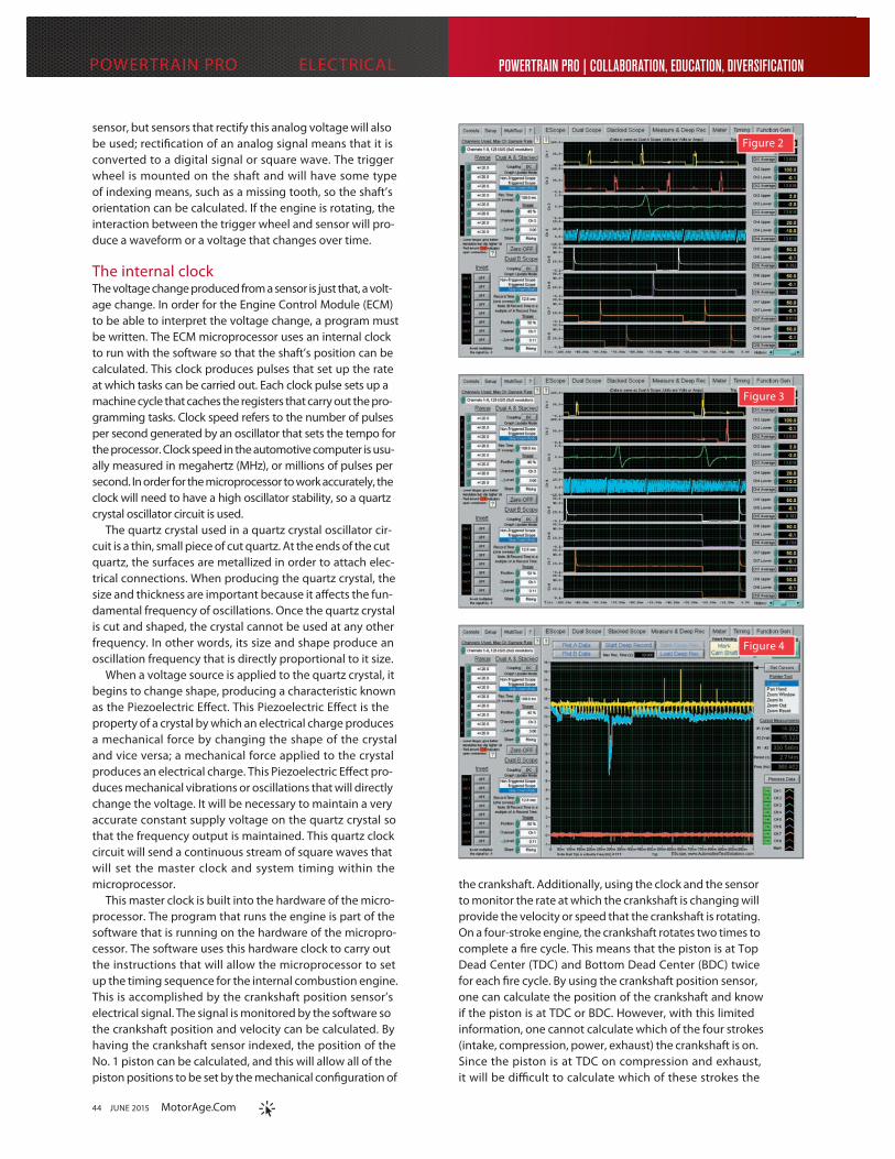
Putting it to workNow that an understanding of the engine timing events has been established, let us look at Figure 2. This is an oscilloscope reading of a good 4-cylinder port-injected engine where the ignition events are shown at the top of the screen, channel 1 (yellow) and channel 2 (red). The cam-shaft position sensor is on channel 3 (green), and the crank-shaft position sensor is on channel 4 (blue). The fuel injec-
tors are on channels 5 (white), 6 (purple), 7 (orange), and 8 (brown). It can be determined that the timing sequence events are occurring in order. The ignition coil packs are a waste spark system and are �ring in sequence one after another in order, each coil �ring on one crankshaft revolu-tion. The camshaft and crankshaft signals are in time and have no breakdown occurring. The fuel injectors are �ring in sequence with the proper injection on time.
In Figure 3, the same engine is having a drivability issue. The oscilloscope capture was taken during an intermit-tent failure. This vehicle had to be driven for 30 minutes to an hour before a “very brief” cut out occurred. As can be determined, the timing sequence events are not occur-ring in order. The ignition events at the top on channel 1 (yellow) and channel 2 (red) have multiple ignition events missing. The camshaft position sensor on channel 3 (green) and the crankshaft position sensor on channel 4 (blue) are in time and have no breakdown occurring. The fuel injectors on channels 5 (white), 6 (purple), 7 (orange) and 8 (brown) are no longer in sequence. These fuel injector events are aligned and the injection on time is commanded for a longer time interval.
The question now is what is occurring with these tim-ing sequence events. Perhaps the most important part of these sequences are the fuel injectors. These fuel injector events are timed sequence events, but during the failure, these events have lost their sequence. The injector events are occurring in a bank �re mode where all the injectors are command on at once. Additionally, the fuel injection on
Figure 5
Figure 6

48 JUNE 2015 MotorAge.Com
POWERTRAIN PRO Ô ELECTRICAL
time has been increased as well. This sequence is what happens when one �rst starts the engine. When starting the engine, the microprocessor does not know where the crank angle space is so it bank �res all the injectors at one time. This strategy insures that the cylinder will have fuel in it when the spark sequence can be calculated by the microprocessor. Once calcu-lated, a spark can be delivered to the air/fuel mixture within the combus-tion chamber, thus igniting it. When the engine is �rst started, more fuel is needed to make a combustible mixture within the cylinder. This additional fuel will wet the induction port, valve and chamber and is the reason the fuel injector on time has been increased.
When the timing sequence events occur like these, the microprocessor is in a reset mode. When a reset mode is activated, the program no longer knows where the engine’s crank angle space is, so it carries out the task of a �rst-start sequence. This problem will be associated with the microproces-sor’s quartz crystal oscillator circuit. When the clock goes down, the pro-gram will restart, causing a reset to occur. This problem can be caused by the powers or grounds to the ECM, an ignition coil that is shorted between the primary and secondary, or can be an internal computer failure. Since the ignition coils have already been checked and are good, one must check the other possibilities. To determine which of these is causing the problem,
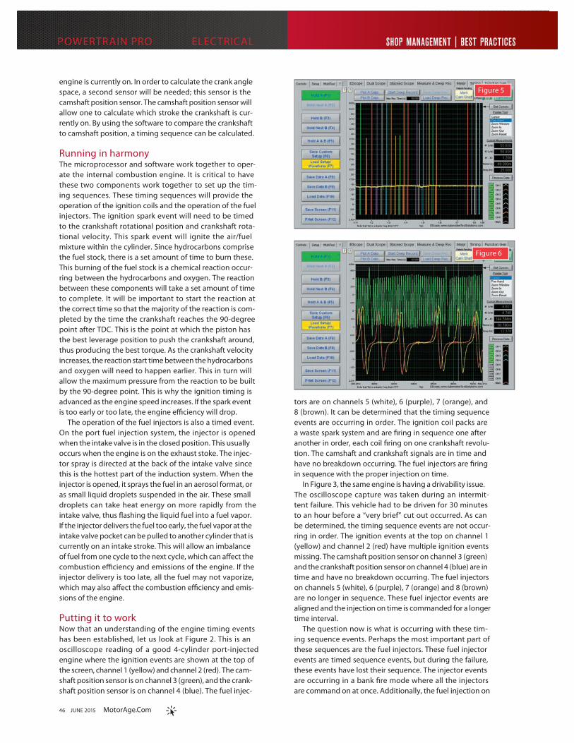
the powers and grounds to the ECM will need to be monitored during the failure. If no problem occurs on the powers or grounds, the problem is internal and the ECM will need to be replaced. In Figure 4, the oscilloscope is connected to all the powers and grounds at the ECM. The vehicle was then driven until the problem reoc-curred. The scope capture shows the powers and grounds being monitored. As can be seen, the power is failing for about 3 milliseconds on channels 4 (blue) and 5 (white) to the micropro-cessor. This very quick power inter-ruption a�ects the quartz crystal oscil-lator circuit causing a computer reset to occur.
Now let us examine another engine exhibiting a drivability problem. In Figure 5, an 8-cylinder port-injected engine injectors are shown. On this oscilloscope capture, the injectors at the left of the screen are in sequence. The oscilloscope channel colors rep-resent the engine’s injector sequence events. The injector sequence is green, orange, red, purple, white, blue, brown, yellow, and then return-ing to green. As you continue across the screen you will see a break in the timing where the red injector event is present followed by a pause. After the pause, the purple then follows, show-ing the sequence is not broken. Again the injector events continue until the orange injector event is followed by a much larger pause. After the pause the red injector event occurs showing the sequence again was not broken. These pauses create a problem where no fuel is injected to the cylinder in the engine, thus creating an engine cut out.
The question now is what is occurring with these injector timing sequence events? It is clear that the injectors are not being activated cor-rectly; it is also clear that the injec-tor event sequence remains intact. This is caused by a software timing error where the algorithm written for the sensor events does not correlate with the actual sensor positions. The software timing is accomplished with the crankshaft and camshaft position sensors. The program uses the micro-processor’s clock to calculate the crank angle space. If the sensors are not in the correct location for the program to
calculate their position, an error within the program occurs. This programming error can create many di�erent timing sequence failures depending on how the program instructions are written.
In Figure 6, the oscilloscope capture is from this same 8-cylinder engine and shows the camshaft position sensors on channel 1 (yellow), chan-nel 2 (red) and the crankshaft position sensor on channel 3 (green). It can be determined that the two camshaft position sensor waveforms are not in the same position compared to the crankshaft position sensor. The red camshaft position sensor waveform is 3.5 teeth after the missing index tooth on the crankshaft position waveform. The yellow camshaft position sensor waveform is 5 teeth after the miss-ing index tooth on the crankshaft position waveform. The red camshaft position signal at 3.5 teeth is in the wrong position. This mechanical tim-ing problem causes the program to be unable to correctly identify the crank angle space, thus creating an injector timing problem.
It is important to understand how the timing sequence events are cre-ated, so when a problem occurs one can quick identify the cause. Pay particular attention to the way these output signals fail. It is not that they failed, but the exact way in which they failed — did the sequence fail, did the commanded time fail, or was a command issued? These are the out-put commands that when incorrect are caused by input errors, software errors or electrical supply errors. Each of these di�erent errors will change the commands in di�erent ways. By monitoring the timing sequence events, some of the most di�cult problems will become routine in your service bay.
BERNIE THOMPSONCONTRIBUTING EDITOR
Bernie Thompson is an automotive diagnostician and trainer, and co-founder of Automotive Test Solutions in Albuquerque, N.M. He is an expert at diagnostics and repair strategy and designs award winning diagnostic tools and software for the automotive industry.
E-mail [email protected]
“The software timing is accomplished with the crankshaft and camshaft position sensors. If the sensors are not in the correct location for the program to calculate their position, an error within the program occurs.” — Thompson