Embed Size (px)
Citation preview

Edbro PLCNelson Street, Bolton BL3 2JJ UK
Tel: +44 (0) 120 4528888 Fax: +44 (0) 120 4531957 E-mail: [email protected] Web: www.edbro.com
EDBRO TRAILER INCLINOMETER
TINC01 (12V AND 24V VERSIONS)
Installation & Operating Instructions
E5541 rev 5 (Sept 2015)

Edbro Trailer Inclinometer – Installation & Operating Instructions E5541 rev 5 (Sept 2015)
Page 1
WARNING!
Before using this product please read and fully understand the instructions provided. ThisEdbro plc product is to be used for guidance purposes ONLY and must not be relied upon toprevent an accident occurring.
Edbro plc or its representatives accept no responsibility for direct or indirect damage orinjury whilst using this product.
SAFETY IS THE SOLE RESPONSIBILITY OF THE OPERATOR

Edbro Trailer Inclinometer – Installation & Operating Instructions E5541 rev 5 (Sept 2015)
Page 2
INTRODUCTION
Vehicle Over turning is a major safety issue within the Transport Industry. The EdbroInclinometer is a cost effective solution that warns the driver when a potentially unsafecondition occurs during tipping.
The inclinometer is supplied in kit form complete with Tractor Cable, Suzi Cable, TrailerCable, Cut-Off Valve and Sensor Unit and should be installed by a competent engineer.
The unit is supplied to suit either a 12V or 24VDC circuit. The voltage dictates whichsolenoid is supplied in the kit.
SYSTEM OPERATION
The inclinometer is intended to measure the angle of the vehicle chassis and alert the driverto an unsafe angle prior to tipping. Chassis angle is displayed on the Display unit LCD screenup to 8 degrees left or right (factory set to 5º)
An alarm limit is set on the control unit which will cause an audio alarm to trigger and thetipper cut-off valve to activate when the chassis angle meets or exceeds the set alarm. Thisaction puts the tipper valve into the hold position.
TO OPERATE:
Switch on the Inclinometer - “EDBRO INCLINOMETER” will be displayed followed by thesoftware version number and then the current set alarm angle.
If the chassis angle is below the set alarm limit then the chassis angle and direction of leanwill be displayed on the LCD. The angle is displayed in whole degrees I.e. 1,2,3 and so onup to the point where the alarm limit is reached.
The system will bleep to the number of degrees indicated on the LCD. e.g. 3 bleep = 3degrees. The volume of these bleeps can be controlled via the volume dial on the front ofthe control unit.
If at any point during tipping (or prior to tipping when the unit is switched on) the set alarmangle limit is reached or exceeded then the system will go into alarm. An audio/visual alarmwill sound in the cab and “DANGER UNSAFE VEHICLE ANGLE” and “VEHICLE OVERTURNRISK” will be displayed on the LCD screen. The tipper cut-off valve will activate preventingthe tipper body from being raised.
At this point the operator should CAREFULLY LOWER THE TIPPER BODY DOWN ONTO THECHASSIS then move the vehicle to level ground before re-attempting to tip. DO NOT MOVETHE VEHICLE WITH THE TIPPER BODY RAISED.
Once tipping is completed the Inclinometer should be switched off.

Edbro Trailer Inclinometer – Installation & Operating Instructions E5541 rev 5 (Sept 2015)
Page 3
Contents of the Inclinometer kit
1 x Inclinometer Control Unit (Serial No: …………)1 x Sensor Unit (Serial No: …………)1 x Data Connection Unit c/w cable loom1 x Valve Unit1 x Suzi Cable2 x Suzi Connector1 x Trailer Cable1 x Sensor Cover2 x Control Unit mounting bracket2 x Grip Knob1 x Override Key1 x Trailer label4 x 2.9 x 9.5 ST screw8 x M4 x 20 pozipan head screw8 x M4 Washer8 x M4 Nylock Nut8 x M5 x 20 Hex Bolt8 x M5 Washer8 x M5 Nylock Nut1 x Quick ref. guide1 x Instruction Manual60 x Black Cable Ties
4 x M5 x 50 Hex Bolt*4 x 25mm spacer*4 x Rubber washer*
* Only required when mounting sensor to rearward facing cross member.

Edbro Trailer Inclinometer – Installation & Operating Instructions E5541 rev 5 (Sept 2015)
Page 4
INSTALLATION ADVICE
IMPORTANT: CAREFULLY READ THIS INSTRUCTION MANUAL BEFORE STARTINGTHE INSTALLATION OF THE INCLINOMETER.
Before mounting the Inclinometer Control Unit, following points should be takeninto consideration:
Ensure the tipper body is empty.
Park the tipper/ trailer in a straight line on firm level ground.
Check for any overhead obstructions before raising the tipper body in particularoverhead power lines
Prop the tipper body following manufacturer instructions before underneath it.
If the vehicle cab has to be tilted forward, ensure all heavy and loose objects areremoved from the cab to avoid any items falling through the windscreen.
The Inclinometer needs to take power from a 12v or 24vDC Ignition switched feed (livewhen the ignition is in the on position). We recommend that power for the Inclinometeris picked up from the following:
o A fuse spare located in the vehicles fuse box. This is often marked ‘Auxiliary’ or‘AUX’.
o Or the vehicle cigarette lighter socket. Be sure to check that it is 12v or 24vDCignition switched.
o Any other suitable 12v or 24vDC ignition switched supply.
o We DO NOT recommend connecting to the following circuits:-
o The braking system (ABS, EBS)
o Engine management
o If you are unsure always consult the vehicle manufacturer handbook.
o Ensure the Inclinometer Control Unit does not obstruct items such as gear shift,brake handle, pedals, switches and other controls.
o The control unit must not obstruct the driver’s line of sight – this can lead toMOT failure.
o When choosing the position for the Inclinometer bear in mind the how easily thecables can be routed and hidden behind the dashboard and facia panels.

Edbro Trailer Inclinometer – Installation & Operating Instructions E5541 rev 5 (Sept 2015)
Page 5
INSTALLATION INSTRUCTIONS
1. Using the two Control Unit mounting brackets, two Grip Knobs and four 2.9 x 9.5 STscrews mount the unit to a suitable location in the cab.
2. Place the Data connection unit behind the dash/fascia of the cab. The ideal position isbehind the passenger foot well panel. Connect the cable marked ‘POWER’ to the vehicleelectrical supply. The BLUE lead is connected to the vehicles ‘GROUND’ or ‘0v’ (on mostmodern vehicles the chassis is ground, always check with a voltage meter). The FUSEDlead is connected to the vehicles 12v or 24v this should be an ignition switched supply.
3. Connect the cable marked ‘SENSOR’ to the sensor socket on the Inclinometer controlunit. The sensor cable needs to be routed through the dash of the vehicle, through thebulkhead to the exterior of the cab. The sensor cable is routed through the vehicle dashand exits through cable gland in passenger foot well (often found on Scania vehicles). Byremoving the cover and the dash panel in the passenger foot well, the sensor cable canbe routed to the outside of the vehicle (some DAF, Foden & other vehicles)
4. Connect the cable marked ‘VALVE’ or ‘AUX’ * to the valve or AUX socket on theInclinometer control Unit. The cable will be marked either ‘VALVE’ or ‘AUX’ depending onspecification and optional accessories supplied with the kit. The valve cable needs to berouted through the dash and brought out behind the PTO control handle.
5. Connect the Valve Unit to the push fit terminals on the end of the valve lead. The leadsto the Valve Unit can be connected up any way round (the valve is not polarised)
6. The Valve Unit has three ports, air in, air out and exhaust. They are marked on the valveas ’IN’, ’OUT’ and ’EXH’. The valve needs to be connected to the PTO airline marked ‘TIP’or ‘UP’. If it is not marked on the rear of the PTO control the correct air line can befound by the following procedure:
With the PTO in the ‘HOLD’ position remove one of the air lines from the connectorsin the rear of the PTO control, it is often better to start with one in the centre(remember which connector you removed the airline from).
With one air line removed, engage the PTO control, and then put the PTO controlinto the ‘TIP or ‘UP’ position. If air escapes from the rear of the PTO control youhave found the ‘TIP’ or ‘UP’ air line.
If no air escapes or air escapes as soon as the air line is removed from the connectorthis is NOT the correct airline. Re-connect the air line to the PTO control and repeatthe procedure with one of the other air lines.
Once you have located the ‘TIP’ or ‘UP’ air line the valve unit needs to be connected so thatit will interrupt it. Make sure the airflow passes through the valve as marked on the valvebody.

Edbro Trailer Inclinometer – Installation & Operating Instructions E5541 rev 5 (Sept 2015)
Page 6
7. The Sensor Cable, which should now be running from the inside of the vehicle to theexterior, needs to be routed under the cab to the Suzi connection point at the rear of thecab.
On most vehicles it can be routed though a gland or electrical cover. Then followingthe vehicles electrical cable loom to the rear of the cab. YOU MAY NEED TO TIP THECAB AT THIS POINT
The Sensor Cable should be secured to the vehicle’s existing cable loom with cableties.
Ensure the cable is not routed such that it can be damaged or trapped when the cabis returned to the normal position and that the cable is kept away from hot surfaces.
8. Mount one of the Suzi Connectors to the rear of the cab. Mount the Suzi using four M4 x20 PAN Screws, four M4 Washers and four M4 Nylock Nuts. Do not fix the Suzi bracketto any part of the cab that will move when the cab is tilted.
9. Mount the second Suzi Connector to a suitable location on the Trailer using the four M4x 20 PAN screws, four M4 Washers and four M4 Nylock nuts.
10. Connect the trailer cable to the Suzi Connector. See wiring diagram below.
Cable wiring colours have changed in kits manufactured from January 2015.
Ensure the equipment is installed according to this amendment and retain this documentwith the Installation and Operating Instruction Manual.
Failure to connect the equipment correctly may result in malfunction of the equipment.
TRACTOR SUZI CONNECTORWire Colours
2015 onwards
Serial# ≥011501
1. BLACK (0v sensor)2. BROWN (sensor)3. GREEN (sensor ground)4. NOT USED5. RED (+v supply to sensor)6. SCREEN7. WHITE(NOT USED)8. NOT USED9. NOT USED10. NOT USED
Before 2015
Serial# ≤121401
1. BLACK(0v sensor)2. BROWN(sensor)3. GREEN (sensor ground)4. White (sensor buzzer signal)5. RED (+v supply to sensor)6. SCREEN7. Grey (NOT USED)8. NOT USED9. NOT USED10. NOT USED

Edbro Trailer Inclinometer – Installation & Operating Instructions E5541 rev 5 (Sept 2015)
Page 7
TRAILER SUZI CONNECTOR
Wire Colours
Example: Serial Number code 121401 = month,month,year,year,i/d number,i/d number = December 2014 number 01
Note: Internal sensor buzzer signal no longer used on 2015 versions
11. Connect the Suzi cable to the trailer and tractor connectors. Linking the trailer to thetractor.
12. Bring the trailer cable out through the cable gland in the side of the Suzi connector androuted down the length of the trailer to the rear most cross member. Leave enoughloose cable at the rear of the trailer to connect the sensor unit. Secure cable using cableties.
13. Install and calibrate the Sensor.
The accuracy of the system depends on the sensor installation being done with precisionand accuracy. The Sensor should be attached to the middle of the rear most cross memberor the nearest one accessible to the rear of the trailer.
Connect all the cables together before fitting the Sensor.
Clean the top of the cross member and place the Sensor on top.
2015 onwards
Serial# ≥ 011501
1. BLACK (0v for sensor)2. BROWN ( sensor output)3. GREEN (sensor ground)4. NOT USED5. RED (+v supply to sensor)6. SCREEN7. NOT USED8. NOT USED9. NOT USED10. NOT USED
Before 2015
Serial# ≤ 121401
1. BLACK (0v for sensor)2. BROWN (sensor output)3. GREEN (sensor ground)4. WHITE (sensor buzzer signal)5. RED (+v supply to sensor)6. SCREEN7. NOT USED8. NOT USED9. NOT USED10. NOT USED

Edbro Trailer Inclinometer – Installation & Operating Instructions E5541 rev 5 (Sept 2015)
Page 8
Switch on the Inclinometer, and observe the reading on the LCD display on theControl Unit. An audible warning should also be heard from the Control Unit andSensor. i.e. 1 beep = 1 degree, 2 beeps = 2 degrees….and so on.
If the cross member is level then the display will show a Zero, and no beep.
Should the Inclinometer show that it is not level, establish which way the trailer isleaning. (+ / -), and make a note of the LCD reading.
The Sensor is very sensitive and can fluctuate between two numbers, so allow itenough time to stabilise.
Disconnect the Sensor, mark and drill a small hole in the cross member, with theSensor being placed in the middle of the cross member. Secure the sensor to thecross member with one bolt which will allow the Sensor to be pivoted to position.Reconnect the Sensor and switch the Inclinometer on. The Sensor can now bepivoted until the previous reading is matched, again allowing for the (+ / -).
Mark and drill the remaining three holes, again test for calibration before tighteningall the bolts, then finally applying a locking solution.
Note: If you are fitting the Inclinometer to multiple vehicles it may be worth investing ina digital protractor which can measure the exact angle of the vehicles chassis. Precisionmounting of the sensor will result in increased accuracy of the Inclinometer.
14. Mount the Sensor Cover over the Sensor Unit using four M5 x 40 HEX bolts. Use Siliconesealant or other waterproof sealant to make a waterproof seal between the SensorCover and the trailer cross member.

Edbro Trailer Inclinometer – Installation & Operating Instructions E5541 rev 5 (Sept 2015)
Page 9
Fig A
The front of the sensor must face towards the cab as in figure ‘A’. Occasionally it is notpossible to mount the sensor directly to a rear cross member so that the front faces the cab.
See figure ‘B’.
Fig B
If the sensor cannot be mounted as shown in fig A above it must be mounted as in fig B.Use the four M5x50 Hex Bolts, four rubber washers & four 25mm Steel Spacers. M5x50 Hex
Bolt, Rubber Washer & 25mm Steel Spacer.

Edbro Trailer Inclinometer – Installation & Operating Instructions E5541 rev 5 (Sept 2015)
Page 10
Circuit Diagram

Edbro Trailer Inclinometer – Installation & Operating Instructions E5541 rev 5 (Sept 2015)
Page 11
OPERATING INSTRUCTIONS
1. Power Switch: The unit must be switched on to operate the tipper.
2. LCD Display: Displays maximum tipping angle at start up followed by the vehiclecurrent angle and direction of camber. It also displays warning messages when it isunsafe to tip. The display is back lit for day/night use.
3. Mode Button: Allows the operator to set the maximum safe tipping angle inconjunction with the Override Key.
4. Volume Control: During tipping the unit will display the current angle of the vehicleand emit audible tones which also indicate the angle. i.e. 1 bleep = 1 degree, 2 bleeps =2 degrees and so on. During normal safe tipping, the volume can be adjusted or evenmuted. If the vehicle angle exceeds the safe tipping angle the system will go into alarmmode where the volume automatically goes to full and can not be adjusted or muted.
5. Power Socket: The power lead is connected to this socket.
6. Sensor Socket: The Sensor Socket has two functions, the first is to connect the sensorlead, and the second is to set the control unit to override in conjunction with theoverride key.
7. Valve or AUX Socket: The valve or AUX lead is connected to this socket.
8. Warning Indicator: Green = OK to tip; Red – Danger! Tipping stopped
1
23
4
5
6
7
8

Edbro Trailer Inclinometer – Installation & Operating Instructions E5541 rev 5 (Sept 2015)
Page 12
Setting the maximum safe tipping angle
The Inclinometer is factory set to 5° maximum safe tipping angle. If the angle of the vehicleexceeds 5° in respect to the horizontal plane it will alarm and prevent the tipper body frombeing raised.
Edbro recommends that you contact your trailer manufacturer to obtain information on itsmaximum safe tilt limit.
To set the maximum safe tipping angle of the inclinometer:
1. Switch the power to the unit OFF.
2. Remove the lead marked ‘SENSOR’ from the sensor socket on the control unit.
3. Insert the override key into the sensor socket.
4. Push and hold the button marked ‘MODE’.
5. Keeping your finger on the ‘MODE’ button, switch the power to the unit ON.
6. When the unit powers up it will display the current maximum safe tipping angle then itwill flash ‘OVERRIDE’ on the display.
7. Keeping the mode button depressed, remove the override key.
8. The display will now start to count up from the minimum available angle to themaximum angle.
9. When the display reaches the desired angle, take your finger off the mode button.
10. Wait a couple of seconds for the unit to store the angle setting and reset.
11. Turn the power to the unit OFF
12. Re-connect the sensor lead and switch the unit on.
13. When the unit powers up, the new maximum safe tipping angle will be displayedmomentarily.
NOTE: The Inclinometer Control Unit should NOT be set to 0° max tipping angle.This will cause the Inclinometer to alarm as soon as it is switched on. The abilityto set the max tipping angle to 0° is for test purposes only.

Edbro Trailer Inclinometer – Installation & Operating Instructions E5541 rev 5 (Sept 2015)
Page 13
TROUBLESHOOTING
Problem Possible Cause/Corrective Action
1. There is no power to the Inclinometer Control Unit.
The unit is powered by ignition feed from the vehicle. The vehicle ignition must be in thePOWER ON position
Check that all the leads to the Inclinometer are in the correct sockets, properlyconnected and the power switch is in the ON position.
The fuse to the inclinometer may have blown, check the 3A blade fuse located at theend of the power supply lead (usually under the vehicle dash where the power has beenpicked up), if this is intact check the 2A fuse which is mounted in the InclinometerControl Unit.
2. The Inclinometer Control Unit shows that it is safe to tip but tipper body willnot raise.
Check that the lead marked ‘valve’ or ‘V’ is correctly connected to the correspondingsocket on the
Inclinometer Control Unit.
Check that the Shut-Off Valve is installed correctly. The valve is marked for air IN andOUT. Also check that it is installed in the PTO airline marked TIP or UP.
Occasionally excessive dirt and moisture in the airline may cause the valve to stick. Trypushing the RED button on the valve to free the valve shuttle. If this fails the valve mustbe replaced.
3. The Inclinometer Control Unit is alarming but the vehicle seems to be on levelground.
The unit will alarm if the chassis angle is greater than the maximum tipping angle set onthe Inclinometer

Edbro Trailer Inclinometer – Installation & Operating Instructions E5541 rev 5 (Sept 2015)
Page 14
4. The Inclinometer Control Unit is alarming but the vehicle seems to be on levelground.
If the Inclinometer Control Unit has been set at a low angle of degrees i.e. <3° it maylook as if the vehicle is alarming on level ground. Try setting the inclinometer at itsmaximum angle setting then read the angle that is displayed.
ALWAYS REMEMBER TO SET THE INCLINOMETER BACK TO ITS ORIGINALSETTING AFTER THIS TEST.
Check that the Inclinometer Control Unit has NOT been set to 0° max tipping angle bymistake. This will cause the Inclinometer to alarm as soon as it is switched on. Themaximum tipping angle is displayed every time the unit is switched on.
Note: The ability to set the max tipping angle to 0° is for test purposes only.
Check the following connections:
o All leads are correctly connected to the Inclinometer control Unit.
o Both sides of the suzi cable are connected correctly.
o The sensor is correctly connected to the trailer cable.
o On a new installation check that the suzi connector has been wired correctly.
o The trailer, suzi, or tractor cable may have been damaged. Check that there is nocable damage from the control unit through to the sensor.
5. The Inclinometer behaves erratically when CB radio, cellular telephone orother transmitting device is used in close proximity to it.
Occasionally powerful transmitting devices or non-legal CB radios/ transmitters mayinterfere with the Inclinometer.
FOR REASONS OF SAFETY DO NOT USE CELLULAR TELEPHONES, CB RADIOS, OR OTHERTRANSMITTING DEVICES DURING THE TIPPING PROCESS.
The use of such devices only serves to distract the operator during the tipping process.
Edbro Trailer Inclinometer – Installation & Operating Instructions E5541 rev 5 (Sept 2015)
Page 15
MAINTENANCE
Providing the installation is done correctly, the Inclinometer should require very littlemaintenance.
Service
The Inclinometer control unit, sensor and data connection unit contain no user serviceableparts. DO NOT OPEN THE UNIT.
For service contact Edbro Service on +44 (0) 1204 902263.
Cleaning
The control unit can be cleaned using a soft damp cloth. DO NOT use detergents, abrasives,solvents or alcohol. Prevent moisture around the power switch and connectors. DO NOTallow liquid to enter the control unit. If any liquid is spilt into the control unit, it should notbe switched on and returned for Repair, stating the cause of the defect.
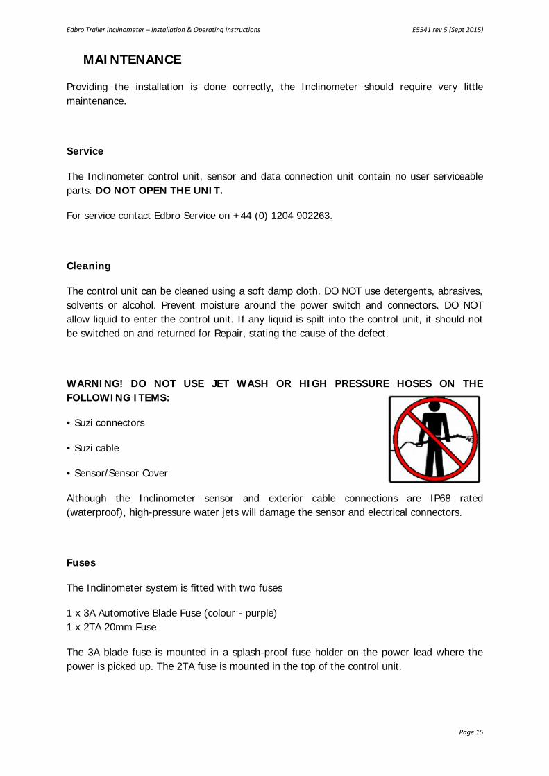
WARNING! DO NOT USE JET WASH OR HIGH PRESSURE HOSES ON THEFOLLOWING ITEMS:
• Suzi connectors
• Suzi cable
• Sensor/Sensor Cover
Although the Inclinometer sensor and exterior cable connections are IP68 rated(waterproof), high-pressure water jets will damage the sensor and electrical connectors.
Fuses
The Inclinometer system is fitted with two fuses
1 x 3A Automotive Blade Fuse (colour - purple)1 x 2TA 20mm Fuse
The 3A blade fuse is mounted in a splash-proof fuse holder on the power lead where thepower is picked up. The 2TA fuse is mounted in the top of the control unit.

Edbro Trailer Inclinometer – Installation & Operating Instructions E5541 rev 5 (Sept 2015)
Page 16
TECHNICAL SPECIFICATIONS
TINC01/12v TINC24V
Display and Sensor
Operating Voltage 12 or 24v DC
Nominal Operating Current 400mA
Measurement Range ± 8° (Factory set to ± 50)
Sensor Operating Temperature -30°C to +55°C
Resolution 1°
Solenoid Valve
Valve Operating Voltage 12vDC 24vDC
Valve Operating Current 170mA
Valve Operating pressure 0-125 P.S.I
Valve Operating Temperature 0° to +50°C

Edbro Trailer Inclinometer – Installation & Operating Instructions E5541 rev 5 (Sept 2015)
Page 17
SERVICE RECORD
Date Details EngineerManufactured and tested.Installed at: …………………………………………………………………………Vehicle ………………………………………………… Reg: …………………


![Untitled-1 [sairushpowersupply.com] Catalogue.pdf5V/10A 5V/20A 12V/5A 12V/10A 24V/2A 24V/5A 24V/10A 60V/1A 60V/2A • Telephone Exchanges / Railways. NOTE: Any Voltage or Current rating](https://img.pdfslide.net/doc/110x75/60947bf0ddc7a728b24390b2/untitled-1-cataloguepdf-5v10a-5v20a-12v5a-12v10a-24v2a-24v5a-24v10a.jpg)