Embed Size (px)
Citation preview
MOBILE VEHICLE TRACKER USING RF (HARDWARE)
TING PICK HUI
This project is submitted in partial fulfillment of the requirements for the degree of Bachelor of Engineering with Honours
(Electronics and Telecommunication Engineering)
Faculty of Engineering UNIVERSITI MALAYSIA SARAWAK
2004

DEDICATION
For my family members and friends,
especially to my mom and dad for your morale support.
iv
ACKNOWLEDGEMENT
First of all, I would like to take this opportunity to thanks my family members especially
my mom and dad for the greatest love and support for all these years. Not to forget, my
brothers and sister for being there when I need them. Meanwhile, I want to sincerely thank
my supervisor for all the guidance and concern on my thesis. Without the encouragement,
care and enlightenment form the supervisor, I will be lost.
This followed by gratitude to the Faculty of Engineering kindness of providing the best
laboratory and complete supplies of components for me to carry out my project. Special
thanks to fellow lecturers especially to Mr. Martin Anyi, Mr. Wan Azlan Wan Zainal Abidin,
Dr. Awangku Abdul Rahman, Mr. Thelaha Masri, Dr. Lim Tiong Heng and Miss Nordiana
for guiding my four years studies.
The phrase "A friend in need is a friend indeed" could be best describe these few friends
of mine. Chong Kok Sheong is the best friend I could ever have. He has been there for me
during my high and low. Not to forget, Chua Chee Seng, Kow Foo Ping, and Loo Wai Chong
who's always be there and caring when I needed help and morale support. Appreciation to
my fellow course mates like Andy Siaw, Chua Tiong Chong, and Lim Kim Hua for your care
and suggestion on the project. Million thanks to every single course mate help me through my
four years of studies here. Last but not least, I would like to convey thankfulness to everyone
who's directly or indirectly contributed to the thesis.
V
ABSTRAK
Kejadian pencurian kereta dalam negara semakin menular-nular kebelakangan ini.
Penggera konvensional bukanlah pilihan terbaik lagi. Kereta yang dicuri lebih sukar dicari
kerana pencuri kereta kebiasannya memotong kereta yang dicuri dan menjualnya sebagai alat
ganti kereta. Alat penjejak digunakan untuk menjejak kereta yang dicuri sebelum sebarang
kerosakkan terjadi kepada kereta yang dicuri. Penjejakkan boleh dibahagikan kepada
penjejakkan frekuensi radio (RF) atau penjejakkan dengan menggunakan Satelit Penempaten
Global (GPS). Penjejakkan dengan menggunakan Satelit Penempatan Global menjejak kereta
dengan menggunakan satelit tetapi it sangat mahal untuk digunakan. Penjejakkan frekuensi
radio menyediakan penjejakkan yang lebih murah dan baik.
Dalam projek ini, kesemua penjejakkan frekuensi radio yang ada haruslah diketahui.
Dengan pengetahuan setiap penjejakkan frekuensi radio yang menggunakan rekabentuk yang
berlainan memberi kesan kepada litar elektronik , pertimbangan wajar adalah penting untuk
menentukan langkah yang dilaksanakan. Dengan menyempurnakan rekabentuk untuk
langkah penjejakkan frekuensi radio, penjejak frekuensi radio boleh dibina. Litar elektronik
yang dipilih dalam peringkat rekabentuk akan dilaksanakan. Apabila peringkat perlaksanaan
telah dijalankan, penjejak frekuensi radio yang sempurna dan boleh berfungsi akan dibina.
VI
ABSTRACT
Car thief incidents have increased tremendously in our country recently. Conventional
alarm is not the best option anymore. Stolen cars are harder to be recovered because car thief
normally cut down the car into small parts and sell then as spare parts. Tracking device is
used to track down stolen car before any harmed could be done on the stolen cars. Tracking
methods are divided into Radio Frequency (RF) tracking and Global Positioning Satellite
(GPS) tracking. GPS track down cars using satellite but it is expensive to implement. RF
tracking could provide a cheaper and better tracking method.
In this project, available RF tracking methods should be known. By knowing each RF
tracking methods utilizing different design and circuitry, careful consideration need to be
taken when choosing which method should be used. By completing the design of the RF
tracking method, the mobile vehicle tracker could be built. The circuit selected during design
stage is used. After going through the implementation stage, mobile vehicle tracker is
completed and tested.
vii

TABLE OF CONTENTS
DEDICATION iv ACKNOWLEDGEMENT v ABSTRAK vi ABSTRACT vii TABLE OF CONTENTS viii - ix LIST OF FIGURES x LIST OF TABLES xi
CHAPTER 1 INTRODUCTION 1.0 Introduction 1-4 CHAPTER 2 LITERATURE REVIEW 2.0 Introduction 5 2.1 Definition of Radio Frequency 6-7 2.2 Types of Radio Tracking Method 7-10 2.3 Types of Antenna System 10-14 2.4 Types of Transmitter and Receiver Used in Tracking 14-17 2.5 Types of Transceiver Used in Tracking 17 - 18 2.6 Timer for Interfacing Circuit 18 - 22 2.7 Types of Communication Port 22 - 25 2.8 Types of Processor for Interfacing Circuit 26 - 29 2.9 Conclusion 29 CHAPTER 3 METHODOLOGY 3.0 Introduction 30 3.1 Project Process Flow 30 - 32 3.2 Flow Chart of Project 33 - 35 3.3 Conclusion 36 CHAPTER 4 DESIGN AND ANALYSIS 4.0 Introduction 37 4.1 Choosing the RF Tracking Methods 37 - 39 4.2 Initial Design and Problems 40 - 41 4.3 Alternative Design and Problems 41-43 4.4 Latest Design and Operation 43 - 50 4.5 Conclusion 51 CHAPTER 5 IMPLEMENTATION 5.0 Introduction 52 5.1 Implementation on the FM Transmitter Circuit 52 - 54 5.2 Implementation on the FM Receiver Circuit 54 - 56 5.3 Implementation on the FM Transceiver Circuit 56 - 58 5.4 Implementing on the Timer Circuit 59 - 65 5.5 Implementation on the Interfacing Circuit 65 - 69 5.6 Conclusion 69 CHAPTER 6 CONCLUSION
viii
6.0 Conclusion 70 - 71 REFERENCES 72 - 76 APPENDIX 77 -114
ix
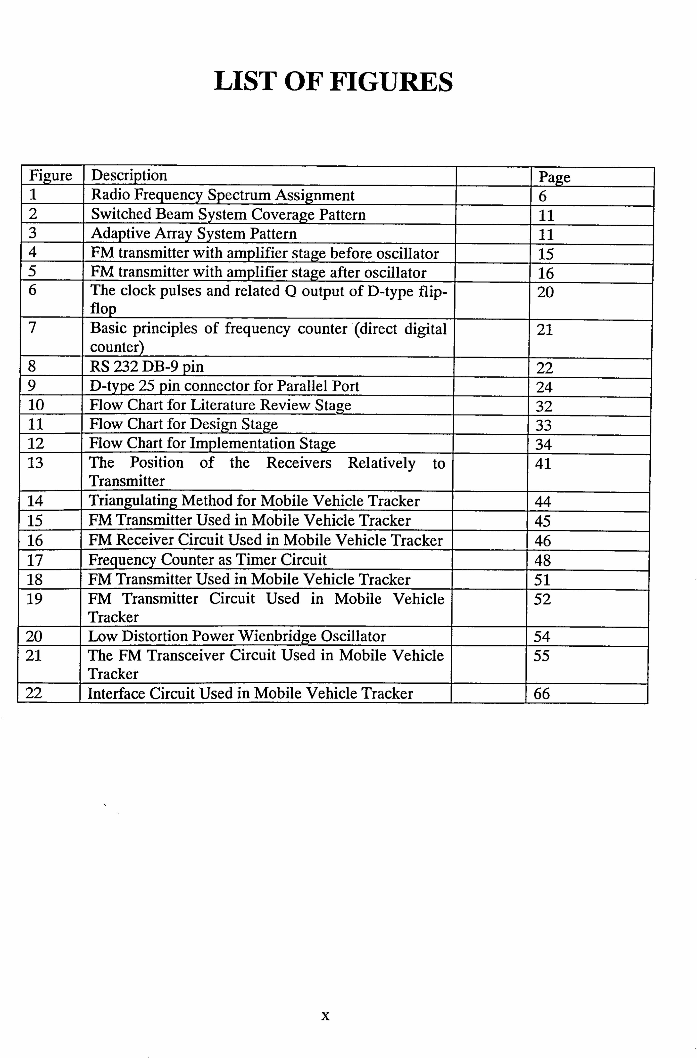
LIST OF FIGURES
Figure Description Page 1 Radio Frequency Spectrum Assignment 6 2 Switched Beam System Coverage Pattern 11 3 Adaptive Array System Pattern 11 4 FM transmitter with amplifier stage before oscillator 15 5 FM transmitter with amplifier stage after oscillator 16 6 The clock pulses and related Q output of D-type flip-
flop 20
7 Basic principles of frequency counter (direct digital counter)
21
8 RS 232 DB-9 pin 22 9 D-type 25 pin connector for Parallel Port 24 10 Flow Chart for Literature Review Stage 32 11 Flow Chart for Design Stage 33 12 Flow Chart for Implementation Stage 34 13 The Position of the Receivers Relatively to
Transmitter 41
14 Triangulating Method for Mobile Vehicle Tracker 44 15 FM Transmitter Used in Mobile Vehicle Tracker 45 16 FM Receiver Circuit Used in Mobile Vehicle Tracker 46 17 Frequency Counter as Timer Circuit 48 18 FM Transmitter Used in Mobile Vehicle Tracker 51 19 FM Transmitter Circuit Used in Mobile Vehicle
Tracker 52
20 Low Distortion Power Wienbridge Oscillator 54 21 The FM Transceiver Circuit Used in Mobile Vehicle
Tracker 55
22 Interface Circuit Used in Mobile Vehicle Tracker 66
X
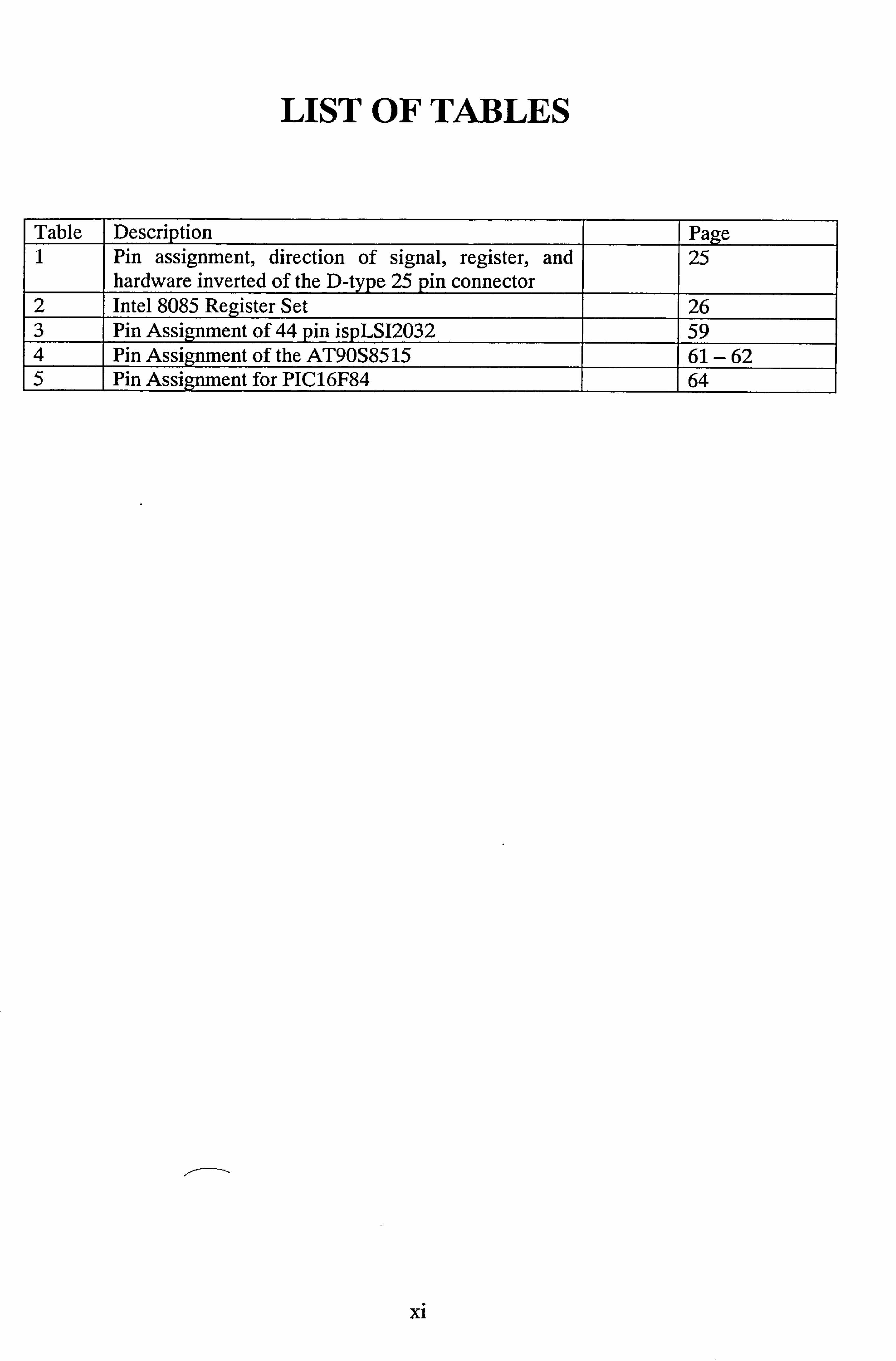
LIST OF TABLES
Table Description Page 1 Pin assignment, direction of signal, register, and
hardware inverted of the D-type 25 pin connector 25
2 Intel 8085 Register Set 26 3 Pin Assignment of 44 pin ispLS12032 59 4 Pin Assignment of the AT90S8515 61-62 5 Pin Assignment for PIC16F84 64
X1
Chapter 1
Introduction
1.0 Introduction
Car thief incidents have increase tremendously in our country in recent years. Conventional
car alarm is not the only protection that can be provided because it is far too common and could
be disarmed easily. Therefore, it is not the best option anymore. If the stolen cars have not being
track down within few hours, the possibility of getting the stolen cars back is very low. Stolen
cars will be total lost because car thief normally cut down the car into small part and sell them as
spare parts. The best backup protection in the market is using tracking device to track down
stolen cars before any damaged can be done on stolen cars. There are two widely known tracking
systems in the market. One of them is utilizing satellite known as Global Positioning Satellite to
track down stolen cars while the other system implementing Radio Frequency (RF) tracking.
Current available market products for tracking mobile vehicle are implementing Global
Positioning System (GPS) but it is relatively expensive. RF tracking is less popular method
because it uncommon. By improvising a new more reliable RF tracking system, all people can
have a better protection for their mobile vehicle at much reasonable price.
1
When talking about mobile vehicle tracking, GPS is definitely the first thing that came into
everyone mind. This system is used by United States (US) government for defensive purposes
but it is open to public used recently. There is 24 Global Positioning Satellite orbit the earth
where a GPS receiver can receive radio signals. It can calculate the receiver position within few
feet if the receiver can receive a signal from at least 3 satellites at a time. This information will
be displayed on computerized map by transmitting the location information to the base station.
There are a lot of advantages by using GPS tracking system. This included it can track down
plentiful of mobile vehicle simultaneously accurately. It will show vehicle current location,
which direction the vehicle is headed, how fast it is going within few minute to computer. The
down sides of GPS are it is expensive, hard to install, and the antenna must install so that it under
open sky. If the mobile vehicle is situated inside a closed area, for example inside cargo
container, underground car parks, garage or even tunnel, the GPS system couldn't detect the
vehicle location. Therefore, GPS system is not suitable for tracking down a stolen car but it is
much better for fleet management. Fleet management is managing transportation of products
from factory to destination.
There is another type of tracking systems. It is using RF and is known as RF tracking
systems. If search online on tracking system, there are abundant companies selling GPS tracking
products while there is hardly any companies producing RF tracking technologies. In RF
tracking system, a radio transceiver which is known as Vehicle Locator Unit (VLU) is set up
inside the mobile vehicle. The VLU stays dormant until the mobile vehicle needs to be tracked.
The VLU is activated by a remote radio activation signals that is transmitted when a specific
2
vehicle is needs to be detected. After the VLU activation, it will send signals that can be received
by receivers. These signals are then pass through the computer and show it on computerized map.
The distance between receiver station and the mobile vehicle can be measured by using angle of
the arrival or signals strength or using both. RF tracking technologies have many advantages in
oppose to GPS tracking system. RF tracking system is more suitable for tracking stolen vehicle.
The tracking capacity of RF tracking system is smaller because there is only small amount of
mobile vehicle simultaneously. It can track virtually unlimited numbers of vehicle and it saves
energy consumption because VLU remains inactive until it is need for tracking the stolen vehicle.
If a well improvise RF tracking system is developed, it will be more easy market penetration and
widespread implementation because of it easier installation processes and inexpensive prices.
The vehicle locator unit that is produce could be hidden within several places in the car is
another advantage. The last but not less advantage is it could find cars that GPS system can't
because the powerful RF signals could pass through close areas such as cargo container,
underground car parks and garage.
Actually RF tracking system can be divided into two types. They are active tracking systems
while the other is passive tracking systems. The passive tracking systems normally set up the
receiver to receive any incoming signals coming from all sources. Therefore, the VLU is sending
information all the times even when we don't want to track that particular mobile vehicle. There
are quite a few disadvantages of using passive tracking systems because the VLU is always on.
The power source of the VLU is easily to get drain because it is always on. Not only that, it will
slow down the tracking of another mobile vehicle at the same time because of signal congestion
3

of unwanted mobile vehicle signals. The better solution to this problem is to use active tracking
systems. Active tracking systems need remote radio activation signals to activate the VLU. After
the activation of the VLU, signals from the mobile vehicle is detected by using at least 3 base
stations and the information is send to the computer to process. The advantages of active tracking
systems by cutting down the power consumption of the VLU power supply. Not only that, the
signal congestion of unwanted signals that from passive tracking systems is free here because
there is only few mobile vehicle that is activated for tracking.
To solve the car thief problem, the most suitable tracking system is RF tracking systems.
With this system, car thief problem could be reduced if not eliminated. This is because the price
of RF tracking systems is much cheaper than GPS tracking systems. Not only that, it can
function better in track down stolen mobile vehicle than GPS tracking systems. The RF tracking
systems must be active tracking system because this will help in track down specific mobile
vehicle with the vehicle locator unit (VLU). This is much more efficient ways to track down
mobile vehicle compare to the passive tracking systems.
4
Chapter 2
Literature Review
2.0 Introduction
Before even start going into the building the whole hardware of RF tracking system,
consideration should be given on knowing the basic of RF tracking. Without strong basic on
these fields, the hardware of RF tracking system build will be very problematic and eventually
unusable. This basic knowledge includes:
1. Definition of Radio Frequency.
2. Types of Radio Tracking Method.
3. Types of Antenna System.
4. Types of Transmitter and Receiver Used in Tracking.
5. Types of Transceiver Used in Tracking.
6. Timer for Interfacing Circuit.
7. Types of Communication Port.
8. Types of Processor for Interfacing Circuit
5
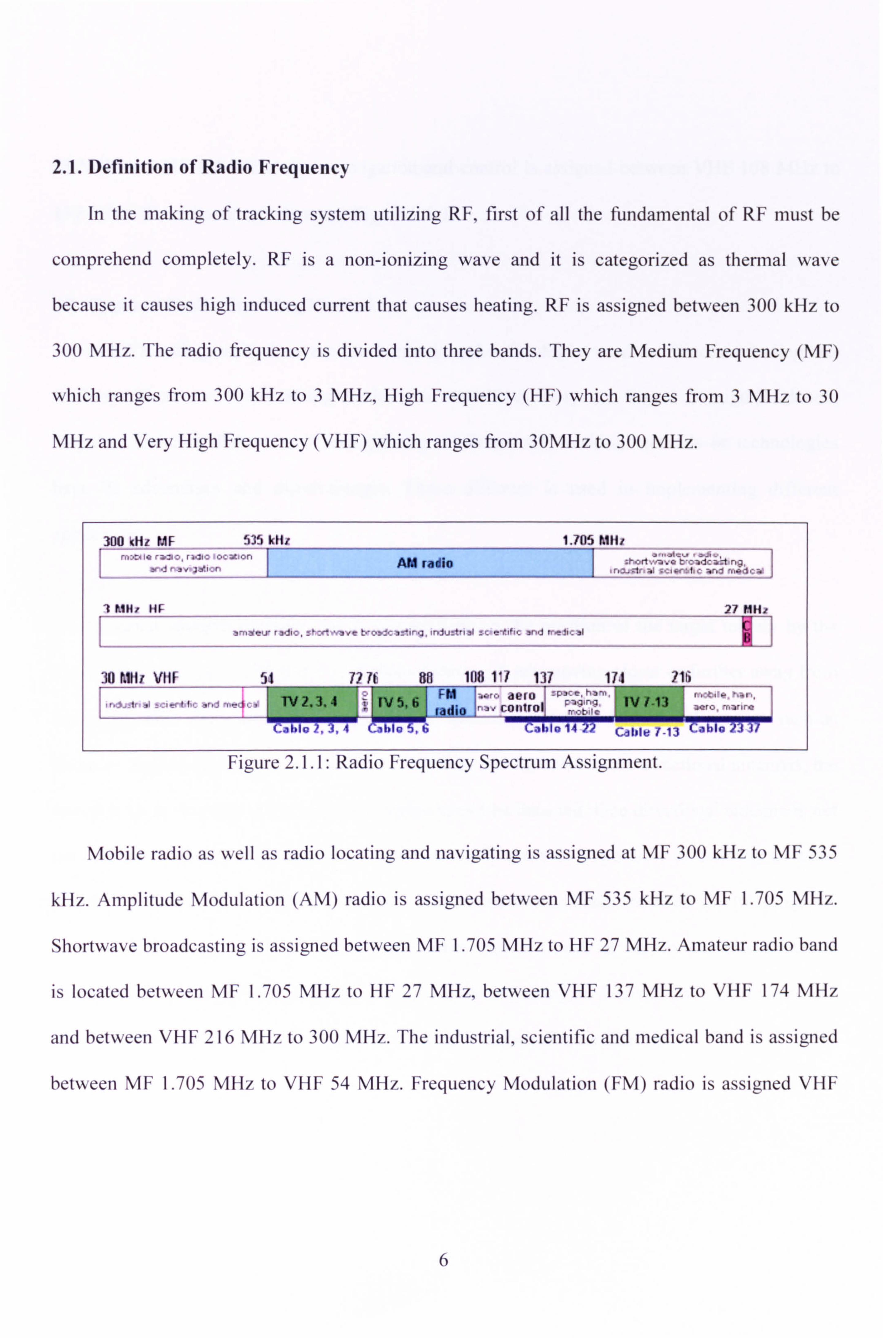
2.1. Definition of Radio Frequency
In the making of tracking system utilizing RF, first of all the fundamental of RF must be
comprehend completely. RF is a non-ionizing wave and it is categorized as thermal wave
because it causes high induced current that causes heating. RF is assigned between 300 kHz to
300 MHz. The radio frequency is divided into three bands. They are Medium Frequency (MF)
which ranges from 300 kHz to 3 MHz, High Frequency (HF) which ranges from 3 MHz to 30
MHz and Very High Frequency (VHF) which ranges from 30MHz to 300 MHz.
300 kHz IdF 535 kHr 1.705 hill. rr,: "C. io ra. yo, raqýo iocYwn
�ý radio rd nav7ýion
ý"�ýýý, srý. crort. vavo O, oadca: t, ng,
ý n; 7r :1 cciKaLc and modcal ..
7 KIM. - HIP 27 MHz
amatev radic, _fxhvave No>. cae'irg, iniutt nal a. c eY. if. r and rnelical
30 ftätr V11F 54 717c 88 108 117 137 171 116 FIII ,. r" aero `'` J,. aelr_eil., ný rnes . 1NZ. 3.4 N5,6 ,; N7-13 1
n', controlj ladi nc o Co hl r 2, A, I (: 110n S" f; al-fl-014 22 LjhIe /-13 ýhlo
Figure 2. I. I: Radio Frequency Spectrum Assignment.
Mobile radio as well as radio locating and navigating is assigned at MF 300 kHz to MF 535
kHz. Amplitude Modulation (AM) radio is assigned between MF 535 kHz to MF 1.705 MHz.
Shortwave broadcasting is assigned between MF 1.705 MHz to HF 27 MHz. Amateur radio band
is located between MF 1.705 MHz to HF 27 MHz, between VHF 137 MHz to VHF 174 MHz
and between VHF 216 MHz to 300 MHz. The industrial, scientific and medical band is assigned
between MF 1.705 MHz to VHF 54 MHz. Frequency Modulation (FM) radio is assigned VHF
6
88 MHz to VHF 108 MHz. Aero navigation and control is assigned between VHF 108 MHz to
137 MHz. These bands are shown in Figure 2.1.1.
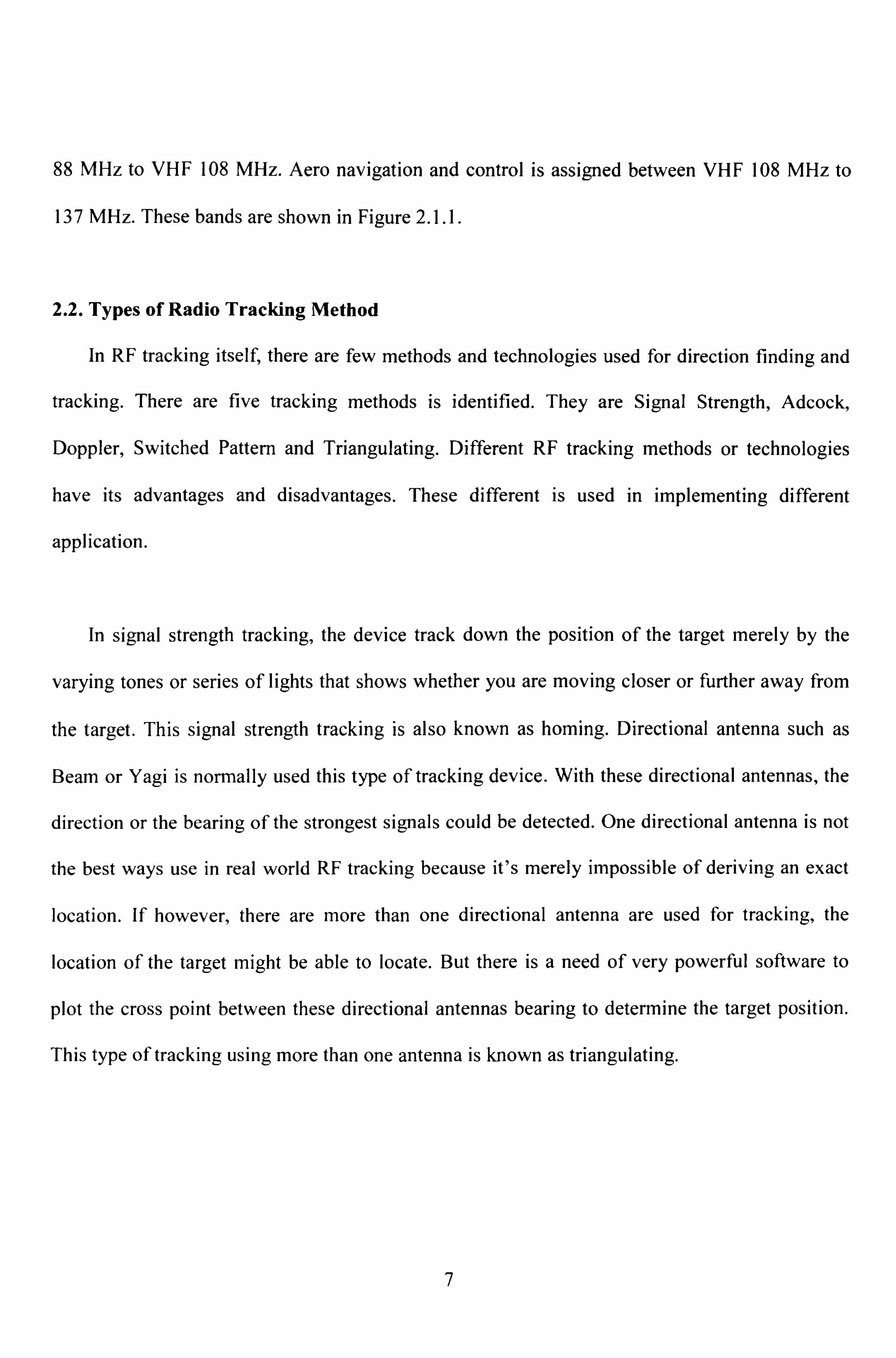
2.2. Types of Radio Tracking Method
In RF tracking itself, there are few methods and technologies used for direction finding and
tracking. There are five tracking methods is identified. They are Signal Strength, Adcock,
Doppler, Switched Pattern and Triangulating. Different RF tracking methods or technologies
have its advantages and disadvantages. These different is used in implementing different
application.
In signal strength tracking, the device track down the position of the target merely by the
varying tones or series of lights that shows whether you are moving closer or further away from
the target. This signal strength tracking is also known as homing. Directional antenna such as
Beam or Yagi is normally used this type of tracking device. With these directional antennas, the
direction or the bearing of the strongest signals could be detected. One directional antenna is not
the best ways use in real world RF tracking because it's merely impossible of deriving an exact
location. If however, there are more than one directional antenna are used for tracking, the
location of the target might be able to locate. But there is a need of very powerful software to
plot the cross point between these directional antennas bearing to determine the target position.
This type of tracking using more than one antenna is known as triangulating.
7
Adcock is another system of RF tracking. Adcock is referred to the technique of deriving
bearing information. In an Adcock system, four vertical antennas in box pattern with a fifth
antenna, called the sense antenna in the middle. With a low profile antenna, the antenna can be
hidden rather easy. Comparisons between transmitter's signals received by the sense antenna and
the four other side antennas done by the appropriate electronics. The comparison results are then
displayed and it tells you where the target transmitter position relatives to receivers. Adcock
tracking systems works the best with vertically polarized antenna and very poor with signals with
mixed polarization. Adcock tracking systems works well with short pulses signal which might be
connected data transmission to and from satellite This method of RF tracking is much larger
than practical mobile tracking. It works much better with tracking down target transmitter in the
cleared area like coast or sea than at crowded area like forest or town because of multi-path
interference.
Other type of RF tracking method is using Doppler system. A Doppler system normally is
assembled with four antennas giving it's the characteristics of 360° device. Doppler receivers are
more like a compass that can track all around its 360°. Severe multipath will cause the signals
seems to be received in every direction even though in theory, a specific direction of signals
incoming will be detected. A Doppler system needs stronger signal to indicate accurately the
wanted signals with the multipath interference through field test. For Doppler systems,
comparison is done on transmitter's signals received by the four antennas through a smart
electronics and it will determine which antenna is closest to the transmitter. Doppler systems are
good in determining bearing but are quite poor in determining range. This doesn't imply that
8

other systems are good in determining range but they could make more accurate extrapolation of
range to the signal strength than Doppler systems. It is harder to operate in crowded area like in
city for Doppler systems. Accurate bearing information with a quick transmission is the main
advantage of Doppler systems. For mobile vehicle tracker applications, the advantages of fast
detecting on the transmission are not that important. Even though, Doppler direction finding is a
viable technique but it is not suitable for mobile vehicle tracker.
Switched pattern technique is another method of RF tracking. Switched pattern involves two
for 180° or four for 360° coverage antennas with switched alternately one at a time of the
receiver. It can switch up to 120 each second. The antenna must affix on roof of a vehicle
because with the approximate "pattern" of the antenna the signal received from the beacon
transmitter will be stronger at one of the antenna in the system. Receiving electronics can
reliably derive bearing information because the system knows which antenna can receive the
signal better and where the vehicle is. Multi-path interference is easier to differentiate due to the
fact that a single antenna is connected to the receiver at a particular time. It is the best solution
for mobile vehicle RF tracking method.
Another RF tracking method is utilizing the concept of triangulating. Two or more signals
bearing coming from different locations (preferably at angles of about 90° to one another) is
implicated in this triangulating method. The more bearings for example more than two, is better
for a better determine the tracking location because of antenna directionality is imprecise. By
using more than two antennas, the precision of locating a tracking beacon on a map is improve
9
tremendously. If the bearing is taken in a relatively short period then significant error no need to
be introduced and vice versa. In this method, if combination could be done with switched pattern
antenna, the beacon could be detected more precisely.
2.3. Types of Antenna System
For the transmitter part, the antenna system should have a radiation pattern of omni
directional. This is because the transmitter should send out its signals in all direction of a single
plane so that the receiver antenna at different location could detect the transmitter signals. The
most suitable antenna that could be use at the transmitter part is a dipole antenna. This is because
it is common and easy to implement. Not only that, it has omni directional radiation pattern that
achieve the requirement of the transmitter antenna systems.
For the receiver part, one of antenna system that has potential in radio frequency tracking is
smart antenna system. From the name, it seems that its antenna is smart but actually it isn't, the
system is. Smart antenna systems have a digital signal-processing capability in transmitting and
receiving in adaptive manner. This adaptive system could change the directionality of its
radiation patterns with the changes in its environment. This help in increasing the performance
characteristics dramatically.
Smart antenna could be categorized into two main groups known as beam switched or
adaptive array systems. The difference between beam switched and adaptive array systems is the
10
beam switched system has a finite numbers of pre-specific patterns while adaptive array system
has infinite numbers of patterns that adjust during real time.
.z Source: http: //www. iec. org/online/tutorials/smart_ant/topicO3. html
Figure 2.3.1 Switched Beam System Coverage Pattern.
Source: http: //www. iec. org/online/tutorials/smart_ant/topic03. html Figure 2.3.2 Adaptive Array System Pattern
Multiple fixed beams with specific sensitivity in a particular direction are formed in beam
switched antenna systems. One of several predetermined, fixed beams are chosen of this antenna
system through detection of signal strength. As the mobile moves from a sector to another, it
switched from one beam to another. Switched beam systems combine the outputs of multiple
antennas to form finely sectorized (directional) beams with more spatial selectivity that can be
achieved with conventional, single-element approaches. This is different with the conventional
11
methods of shaping the directional antenna pattern with metallic properties or physical design of
a single element (like sectorized antenna).
The most advanced smart antenna nowadays is known as adaptive antenna technology. This
adaptive has an advantages of locate and track various types of signals effectively to dynamically
minimize interference and maximize intended signal reception. The adaptive provides optimal
gain while simultaneously identifying, tracking, and minimizing interference signals.
Omni-directional could be easily differentiated from the intelligent antenna by the numbers
of antenna element implemented. Both switched beam and adaptive array system share the
similarities in the hardware characteristics with the intelligent counterpart. They are
distinguished primarily by their adaptive intelligence. An array of antenna elements typically 4 to
12 elements are needed for directionally sensitive information for process. These elements could
be arranged in linear, circular, or planar configurations. This smart antenna system smart because
of its digital signal-processing facilities. Numerous advantages in terms of accuracy and
flexibility of operation are offer by electronic systems today through manipulation of RF data in
digital format.
Even though, a smart antenna systems will be a great advantages to radio tracking system,
this system is hard to get in the market and it is still in its early stage of development. Both the
antenna and the intelligent systems are hard to get and the algorithm itself are very rare. It's hard
12
to implement in this project but maybe in further future, this is not impossible and at that time,
this RF tracking efficiency will increase enormously.
Another suggestive solution for an antenna system is using more mechanical part. The
mechanical part is actually control by electronic. That is different from the smart antenna system
that is using pin diodes to control the parasitic element and thus control direction of the receiver
antenna. Implement a good operational directional antenna and mounted it on a stepper motor
that is connected to a control circuit. This stepper motor is control to tune on to the strongest
signal received from the transmitter. If the directional antenna located the strongest signal
received at a specific bearing, it will send the bearing data to the computer to process. Even this
method is not as smart as the smart antenna systems, it is the most economical and yet easy to be
build compare to a complex smart antenna systems.
A directional antenna such as Yagi-Uda antenna is easy to build. The problem is of this
system is to design an operational antenna with relatively small in size problem concern on
multipath interference signals. A better solution to this multipath interference is using a smaller
antenna with very small beam width. This is because with smaller beam width, the scanning
process could be more precise. When using directional antenna such as Yagi-Uda antenna, the
beam width is too broad to use in tracking. An alternative to using Yagi-Uda antenna is by much
smaller beam width antenna such as patch antenna. The polarization of both antennas should be
vertically polarized. This is because the transmitter antenna should transmit in omni directional
13
and the receiver antenna should use the same polarization of the transmitter antenna to receive
correctly.
2.4 Types of Transmitter and Receiver Used in Tracking
In radio frequency tracking, a transmitter which is sending a pulsed signal out in every
direction so that the receiver could pick up the pulsed signal is needed. At the receiver ends, the
receiver must be able to detect pulsed signals. This detection is depending on different methods.
The detection is depended on the signals strength, signal direction of arrival or other parameters.
Therefore, the both design of the transmitter and receiver should be similar in frequency transmit
and receive.
For the transmitter, a suitable frequency should be selected so that the transmitter could be
build easily and yet the directional antenna such as Yagi-Uda antenna size will be decrease. A
frequency in 100 MHz and above that is not interfered with local radio station frequency will be
the best frequency. This is because transmitter circuit within radio station frequency range is
easy to build because it is quite common. The frequency above 100MHz is selected because for a
directional antenna, such as Yagi-Uda antenna will have smaller size if the frequency is high.
This is because frequency is inverse proportional to the wavelength and the wavelength is
proportional to antenna size. Therefore, both transmitter and receiver should be transmitting and
receiving signals frequency ranges 100MHz and above.
14

There are several transmitter circuit that could used and implement on this project. These
transmitter circuits could be easily obtained online. Some of the circuits are home-brewed but
most of the circuits that is posted online are done by people involve in amateur radio worldwide.
From all the circuits online, it noticeable that they could be divided into two large sections
known as Frequency Oscillator or Modulator and Amplifier Stage.
The most important section of the transmitter is the frequency oscillator or modulator. This
part of the FM transmitter normally could contain oscillator which consist of capacitor and
inductor. Tuning the oscillator could be done by varying the capacitor or inductor. By fixing the
inductance, the capacitance should be varied and vice versa. Colpitts Oscillator is one of
oscillator that used varying inductor or capacitor.
zzx
nic
I"
22n
sex 11 47x
J",. ) BC547
100n
114
6-45pF
TRIM CAP
AERIAL
T I
T (1-61T
BC647
2 S. 6p
47dR
Zip 3-SVA
22nT
Source: electronickits. com/kit/complete/surv/ck200. pdf Figure 2.4.1: FM transmitter with amplifier stage before oscillator
The other section of the transmitter is amplifier stage. Some of the circuits contrast from
each other in number of amplifier stages. All FM transmitters have amplifier stage. Some have
15