Embed Size (px)
Citation preview

INSTAI I .anoN, OPERATION, MAINTENANCE MANUAL
'
1RUC'n0fi CAR:!AA.I.Y IO OR.Met
I 11.A.Ctaltft A CCftftfCT fUN'Cl10H lbfQ .
TIRE CHANGER

1. Warning Sign
1
2
3
4
5
6
2 • 15
Keep safety for electrified devices.
Do not put your leg between the bead breaker are and the tire when
the bead breaking is used.
Do not put your hand between the tire and turntable when machine is
operated.
Do not put your hand between the M/D head and the tire.
It is forbidden to put your hand or tools in the claws when they are
opened or closed.
Do not stand behind the vertical arm when machine is operated.
I

2. Introduction
Thank you for purchasing our tire changers. The machine has been
manufactured in accordance with the very best quality principles. This manual
is one integral part of the product. Before using the tire changer, read carefully
the warnings and instructions contained in this manual since they provide
important information on operation safety and maintenance.
Keep this manual for future reference.
1). Techn ical Data
Max tire diameter 1000mm
Internal locking rim dimensions 10" -18"
External locking rim dimensions 12 "-20"
Force on bead breaker blade 2000Kg
Working pressure 0.8--1.2Mpa
Power supply voltage 220V /11 OV /380V
Motor power 1.1 kw/0. 75Kw
Noise level in working conditions <70dB
2). Description of Machine
1. Reverser Control Pedal
2. Bead Breaker Control Pedal8-----···-----·
3. Clamp Control Pedal
4. Jaw
5. Turntable
6. M/D Head
7. Hex Arm
8. Swivel Arm
9. Tire Pressing Rubber
10. Bead Breaker Blade
11. Bead Breaker Arm
12. Column
13. Locking Handle
3 - 15

3. Safety Requirement
1). Usage
This tire changer has been designed and manufactured exclusively for
removing and mounting tires from/into rims from 1 O" to 21" and a maximum
diameter of 1000mm.
Any other use is to be considered incorrect and unreasonable.
In particular THE MANUFACTURE can't be held responsible for any damage
caused through the use of this tire changer for purposes other than those
specified in this manual, and therefore inappropriate, incorrect and
unreasonable.
2). General Safety Precautions
This tire changer may only be used by specially trained and authorized expert
personnel.
Any tampering and modification to the equipment carried out without the
manufacturer's prior authorization will free him from all responsibility for
damage caused directly or indirectly by the above actions.
The tire changer comes complete with instructions and warning transfers
which are designed to be long-lasting. If they should for any reason be
damaged or destroyed, please ask immediately for replacements from the
manufacture.
Keep it away from combustible, explosive objectives, avoid strong light,
sunshine, and keep it in good ventilation.
Make sure to use original spare parts and accessories, installed by authorized
personnel according to manual.
Be careful if there are any dangers happen, stop the machine, contact
manufacturer.
Non-operation personnel should be kept away from the machine.
Operators should be protected by protective (glove, eye-protection glasses,
and working-clothes) to avoid any accidental injuries.
4. Transport
This tire changer must be transported in its original packaging and kept in the
position shown on the package itself.
4- 15
f' I

The packaged machine may be moved by means of a fork lift truck of suitable
capacity. Insert the forks at the points shown at figure below.
5. Unpacking
Use proper protection tools to unpack (gloves etc)
Check that the equipment is in perfect condition 1 making .sure that no parts are
damaged or missing, if in doubt do not use the machine and contact your
retailer.
Put the packing materials (plates, nails, screws, plastic bags) in safety place.
6. Installation.
1). Space Required
When choosing the place of installation is sure that it complies with current
safety at work regulations.
This machine must be connected to the mains electric power supply and the
compressed air system. It is therefore advisable to install the machine near
these power sources.
The place of installation must also provide at least the space shown in figure
below so as to allow all parts of the machine to operate correctly and without
any restriction.
5 - 15

500ftfl
If this machine is installed outside it must be protected by a lean-to.
2). Commission
Before making the connections, check that the characteristics of your systems
correspond to those required by the machir)e.
Even small jobs done on the electrical system must be carried out by
professional personnel.
Connect the machine to the electrical network, which must be provided with
line fuses, a good earth plate in compliance with regulations in force and it
must be connected to automatic circuit breaker.
Warning: Should the tire changer be lacking in electric plug, so the user must
set one, which is at least 16A and which conforms to the voltage of the
machine, in compliance with the regulations in force.
3). Operation Test
When the pedal (1) is pressed down the turntable should turn in clockwise
direction. When the pedal is pulled up the turntable should turn in the
anticlockwise direction.
Warning: if the turntable turns in the opposite direction to that shown, reverse
the wires in the three-phase plug.
Pressing the pedal (2) activates the bead breaker; when the pedal is released
the bead breaker returns to its original position.
Pressing the pedal (3) opens the four clamps; when the pedal is pressed
again they close.
Pressing the pedal (4) tilts the arm; when the pedal is pressed again it returns
to its working position.
6 - 15

When the pedal located on the left side of the machine is pressed dowh to the
first gear, air is released from the airline gauge. Gauge will indicate the
pressure after release of air.
When the pedal located on the left side of the machine is pressed down to the
second gear, air is released from the airline gauge along with a powerful jet
from the nozzles located on the turntable clamps. This part is suitable for the
machines which contains the quick inflation system.
Don't lean on the turntable during this operation, possible dirty dust on the
turntable could offend the operator's eyes. For the same reason, be carefully
as not to accidentally push the inflating pedal while working.
7. Operation
Don't use the machine until you have read and understood the entire manual
and the warnings it provides.
The operation of the tire changer is divided into three parts:
1 ). Breaking the bead
2). Demounting the tire
3). Mounting the tire;
Warning: before carrying out any operation, deflate the tire and take off all the
wheel balancing weights.
1). Breaking the bead
Warning: when the bead breaker pedal is operated, anything within the action
range of bead breaker arm can be in the danger of being crushed.
Check that tire is deflated, if not, deflate it.
Close the turntable clamps completely.
Warning: bead breaker with the clamps in the open position can be extremely
dangerous for operator's hands; during the bead breaking operations never
touch the side of the tire.
Position the wheel against the rubber stop on the right side of the tire changer.
Position the bead breaking blade against the tire bead at a distance of about 1
cm from the rim. Pay attention to the blade, which must be correctly onto the
tire not onto the rim.
Press down the pedal (2) to activate the bead breaker and release it when the
blade has reached to the end of its travel or in any case when the bead is
broken.
7 - 15

Rotate the tire slightly and repeat the , operation around the entire
circumference of the rim and from both sides until the bead is completely
detached from the rim
Figure 7-1
2). Demounting the Tire
Figure 7 .. 2
Before any operations remove the old wheel balancing weights and check that
the tire is deflated.
When tilting the vertical arm; be sure· that nobody stands behind the tire
changer.
Press down pedal (4), tilt the vertical arm.
Spread the grease onto the tire bead.
Failure to use the grease risks causing serious damage the tire bead. ,
When clamping the tire, never have your hands under the tire. To clamp the
tire correctly, position the wheel exactly at the center ofthe turntable.
Rim locking from outside:
Position the clamps according to the reference mark on the turntable by
pressing the pedal down to its intermediate position.
Place the tire on the clamps and, keeping the rim pressed down, press the
pedal (3) as far as it will go.
Rim locking from inside:
Position the clamps so that it they are completely closed.
Place the tire on the clamps and press down the pedal (3) to open the clamps
and thereby lock the rim.
Make sure the rim is firmly fixed to the clamps.
I

Press the pedal (4), restore the vertical arm to its working position.
Push out the locking button in the handle, release hex bar.
Lower the hex bar until the mounting tools rests against the edge of the rim.
Then lock it using the locking button in the handle. This way the mounting arm
is locked in a vertical and horizontal direction and the mounting head is
automatically moved to a distance of about 2mm from the rim.
Do not put hands on the wheel, when moving the mounting arm to its working
position your hand could be crushed between the rim and the mounting head
with the crowbar inserted between the bead and the front section of the
mounting head, move the tire bead over the mounting head.
WARNING: In order not to damage the inner tube, it there is one, it is
advisable to carry out this operation with the valve 10cm to the right of the
mounting head.
Chains, bracelets, loose clothing or foreign objectives in the vicinity of moving
parts can cause danger to the operator.
With the crowbar held in this position, rotate the turntable in a clockwise
direction by pressing down on pedal (1) until the tire is completely separated
from the wheel rim.
To prevent industrial accidents, keep hands and other parts of the body as far
as possible from the tool arm when the table top is turning.
Remove the inner tube if there is one, need not release the mounting arm,
press down pedal(4),directly tilt the vertical arm.
Repeat the operation for the other tire bead
Figure 7-3 Figure 7-4
9-15
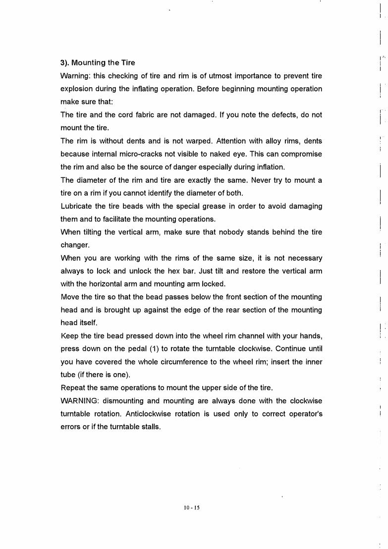
3). Mounting the Tire
Warning: this checking of tire and rim is of utmost importance to prevent tire
explosion during the inflating operation. Before beginning mounting operation
make sure that:
The tire and the cord fabric are not damaged. If you note the defects, do not
mount the tire.
The rim is without dents and is not warped. Attention with alloy rims, dents
because internal micro-cracks not visible to naked eye. This can compromise
the rim and also be the source of danger especially during inflation.
The diameter of the rim and tire are exactly the same. Never try to mount a
tire on a rim if you cannot identify the diameter of both.
Lubricate the tire beads with the special grease in order to avoid damaging
them and to facilitate the mounting operations.
When tilting the vertical arm, make sure that nobody stands behind the tire
changer.
When you are working with the rims of the same size, it is not necessary
always to lock and unlock the hex bar. Just tilt and restore the vertical arm
with the horizontal arm and mounting arm locked.
Move the tire so that the bead passes below the front section of the mounting
head and is brought up against the edge of the rear section of the mounting
head itself.
Keep the tire bead pressed down into the wheel rim channel with your hands,
press down on the pedal (1) to rotate the turntable clockwise. Continue until
you have covered the whole circumference to the wheel rim; insert the inner
tube (if there is one).
Repeat the same operations to mount the upper side of the tire.
WARNING: dismounting and mo1,1nting are always done with the clockwise
turntable rotation. Anticlockwise rotation is used only to correct operator's
errors or if the turntable stalls.
10 - 15

8. Moving
Move the tire changer you need a fork-lift truck.
Disconnect the pneumatic and electric power supplies.
Apply leverage to one side of the base so as to raise it slightly from the floor,
Insert the forks of the truck under the base and slide the tire changer onto
them.
Set the tire changer down in its new position.
9. Storage
In the event of storage for long periods of time, make sure to disconnect all
sources of power and grease the clamp sliding guides on the turntable to
prevent from oxidizing.
10. Scrapping
If you decide scrape the machine, be sure to make it inoperative by
disconnecting it from all sources of power.
Remove all non-ferrous materials and dispose of them as prescribed by
national law.
Collect the oil and dispose of it at an authorized point as prescribed by
national law.
Scrape the rest ferrous material.
11 - 15

11. Maintenance
1) General warning
Unauthorized personnel may not carry out maintenance work.
Regular maintenance as described in the instructions is essential for correct
operation and long lifetime of the tire changer.
If maintenance is not carried out regularly, the operation and reliability of the
machine may be compromised, thus placing the operator and anyone else in
the vicinity at risk.
Before carrying out any maintained work, disconnect the electric and
pneumatic supplies. Moreover, it is necessary to break the bead load less 3-4
times in order to let the air in pressure go out of the circuit.
Defective parts must be replaced exclusively by expert personnel using the
manufacture's spare parts.
Removing or tampering with safety devices (pressure limiting and regulating
valves) represents a contravention of safety regulations.
In particular, the manufacturer shall not be held responsible for complaints
deriving from the use of spare parts made by other manufacturers or for
damage caused by tampering or removal of safety systems.
2). Maintenance Operations
Clean the turntable once a week with diesel fuel so as to prevent the
formation of dirt, and grease the clamp sliding guides.
Carry out the following operations at least once every 30 days:
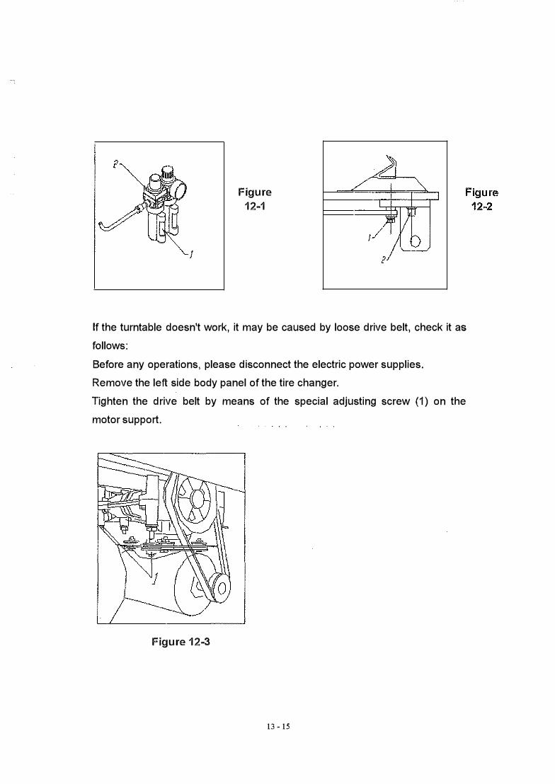
Check the oil level in the lubricator tank. If necessary, fill up by unscrewing
screw 2; only use SAE30 oil (figure 12-1)
12 - 15
J
Figure
12-1
If the turntable doesn't work, it may be caused by loose drive belt, check it as
follows:
Before any operations, please disconnect the electric power supplies.
Remove the left side body panel of the tire changer.
Tighten the drive belt by means of the special adjusting screw (1) on the
motor support.
Figure 12-3
13 • 15

llf the clamps open/close slowly, it should be preceded as follows: (1 ). Clean the turntable (2). Adjust the air valve bolt.
If the bead breaker opens/closes does not flexible, it should be preceded as follows: (1 ). Check whether the air tank got any leaks or not. (2). Adjust the air valve bolt.
Figure 12..S
14 - 15

12. Electric Connection Diagram
r�����������
N----i--��-�----�
PE-- --·-------.:/i r --·
i i..·-·
NIL2 11: ii
I I
I ...-2-0
1____,
I L ___ �
110V /220-
11-11: >< 9-10 >< 7-8 >< 5-6
'.3-4
l-2 >< D R
R ��--�------------S -----+-�-----------
T ----+-��-----------
11-12 ;,: 7-8 ><
5-6
-4
1-1: ><
���� L
PE - - - -
><
><
><
D R
r I L _ _J
-------------:;;.
15 - 15
-R
-R

TYR.E· CHANGER l·NS�f�LLATION,OPERATION,·MAINTENANCE MANUAL
'"; ,\ . ' '
' , '
KEEP TME MANJAL NEAR THE P..+1ACHINE ALL TIME
AND MAl<;J �iURE ALL USERS HAVE READ TH1S

Table of Contents
Technical Specifications ............... : .............. '.1Specifications · .... · · · · · · · · · · · .... · .... · · .... · · · · · · .. · 1
Applicable Range · · · · · · · · · · · · · · · ... · ... · · ..... · · · · · · 1
.Structure 1•• • • • ••••••• ················� • ••••••• • •••••••••••••• 1
Installation ·0•••••••••••••••••••••••••••••••••••• .. •••1·······2
Operation Procedures .................................. 2Demounting · .. · .. · .. · .. · · · · .. · .. · .... · · · · · ........ · .. 2Mounting .. · .. · · · · · · .. · · · · · .. · · · · · · · · .. · · · .. · · · · .... ,. · · 3Inflating · · · · · · · ... · · · · · · ...... · · .. · · · · · ..... · · · ........ · 3
Package & Transport .. · · .. · ................. · · .......... 4Maintenance ........................................... ; .... 4Troubleshooting • · · · · · · · · · · ..... · · · · · · .. · · · · · · · · · · · · · · · · · ·7
ii
Technical Specifications
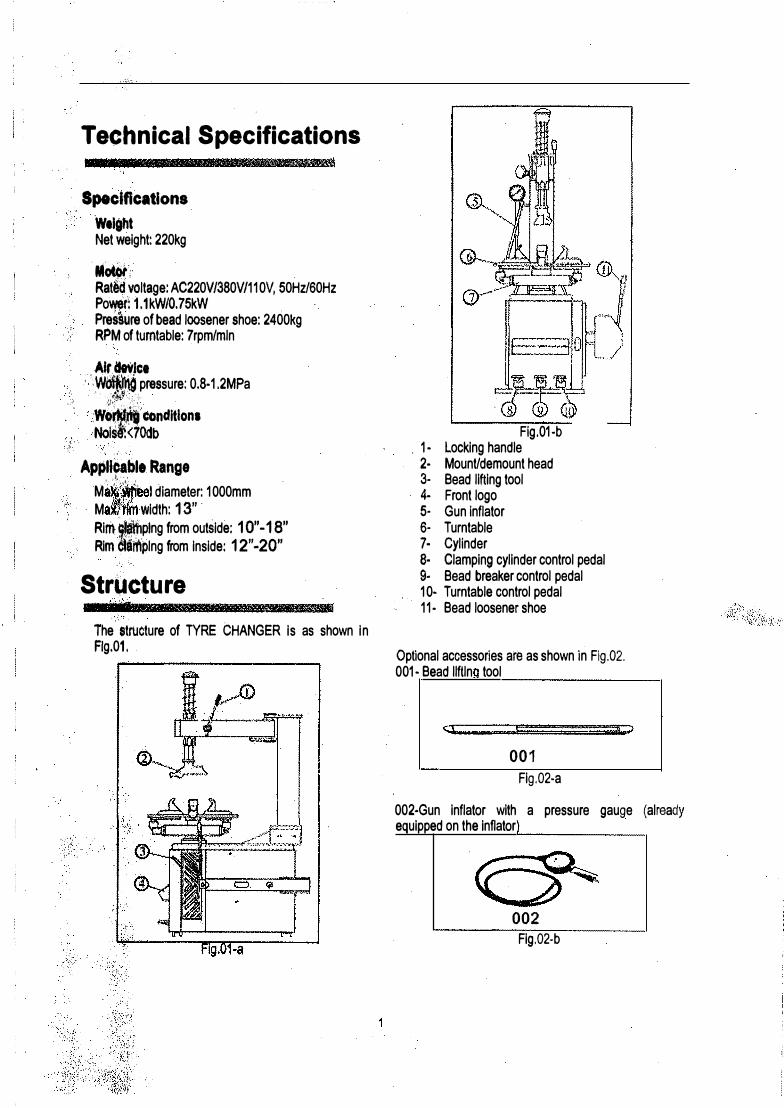
Specifications Weight Net weight: 220kg
.Motor, Rat� voltage: AC220V/380V/110V, 50Hz/60Hz Power� ·1.1kW/O. 75kW Pressure of bead loosener shoe: 2400kg RPM of turntable: 7rpm/mln
Alr.clevlc:t ; 'Woi)!hO pressure: 0.8-1.2MPa
,. , ' . ' ' ·;:;���'}:)_'
. : ::=��ndltlon,
,, .,·._ ,
Applicable Range . <--}\:t-'·.: .
M · I diameter: 1000mm· · M Width: 13"
Rim �afhplng from outside: 1 O" -18" Rim !tifflplng from Inside: 12"-20"
Structure
The t1tructure of TYRE CHANGER Is as shown In Flg.01.
Fig.01-b . 1- Locking handle 2- Mount/demount head3- Bead lifting tool4- Front logo5- Gun inflator6- Turntable1· Cylinder B· Clamping cylinder control pedal 9- Bead breaker control pedal10- Turntable control pedal11· Bead loosenershoe
Optional accessories are as shown in Fig.02. 001- Bead llftln tool
001
Fig.02-a
002-Gun inflater with a pressure gauge (alreadyequipped on the Inflater
002
Fig.02-b

Installation
Installation requirements: • Install TYRE CHANGER close to the main
power and air compressor system.• The minimum installation space of TYRE
CHANGER is as shown in Fig.03, which canensure the free operation of tiremounting/demounting.
s It is necessary to build a protective shield for TYRE CHANGER if it is installed outdoors.
!II Do not operate TYRE CHANGER if there is flammable gas.
960mm
Fig.03-a
·1100mm
2
Fig.03-b Note: + It is suggested to keep at least 500mm
distance between TYRE CHANGER and thewall.
+ Holes are prepared on the chassis of TYRE ,CHANGER Be sure to fix it to the groundwith expansion bolts. Otherwise, it maycause loud noise.
Operation Procedure� --·-&B"JR\U--
Note: Operators of TYRE CHANGER must be trained · and qualified.
Demounting
Preparation • Release all the air inside the tire.• Remove the counterweight on the wheel. (See ·
Fi .04.
Fig.04
Demounting Tire • · Place the tire between the bead loosener shoe
and tire control rubber, and make the shoebetween the bead and tire, about 1cm to the bead. And then step on the tire control pedal (see 9 of Fig.01) to separate the bead from the rim. See Fi .05 .
Fig.05
Note: Lubricate the bead with thick soap suds before demounting the tire, so as to avoid wear and worn.
I
r
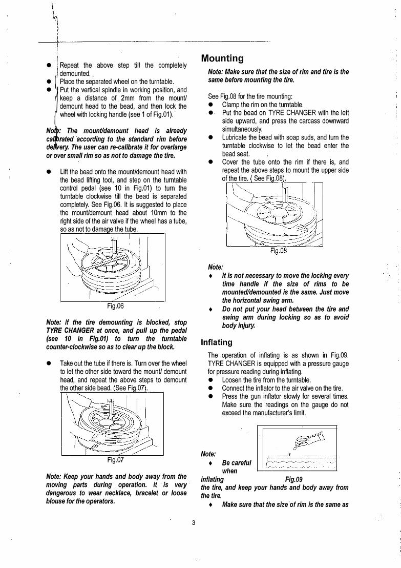
• JI Repeat the above step till the completelydemounted ..
• ( Place the separated wheel on the turntable.•
1 Put the vertical spindle in working position, and
( keep a distance of . 2mm from the mounU demount head to the bead, and then lock the
{ wheel with locking handle (see 1 of Fig.01). ·
Not
: The mount/demount head is already call rated ·according to the standard rim before del. ery. The user can re-calibrate it for overlarge or over small rim so as not to damage the tire.
• Lift the bead onto the mounUdemount head withthe bead lifting tool, and step on the turntablecontrol pedal (see 10 in Fig.01) to turn theturntable clockwise till the bead is separatedcompletely. See Fig.06. It is suggested to placethe mounUdemount head about 10mm to theright side of the air valve if the wheel has a tube,so as not to dama e the tube.
Fig.06
Note: If the tire demounting is blocked, stop TYRE CHANGER at once, and pull up the pedal (see 10 in Fig.01) to turn the · turntable counter-clockwise so as to clear up the block.
• Take out the tube if there is. Turn over the wheelto let the other side toward the mounU demounthead, and repeat the above steps to demountthe other side bead. See Fi .07 .
Fig.07
Note: Keep your hands and body away from the moving parts during operation. It is very · dangerous to wear necklace, bracelet or loose blouse for the operators.
3
Mounting
Note: Make sure that the size of rim and tire is the same before mounting the tire.
See Fig.08 for the tire mounting: • Clamp the rim on the turntable.
. •. Put the bead on TYRE CHANGER with the left side upward, and press the carcass downward simultaneously.
• Lubricate the bead with soap suds, and turn theturntable clockwise to let the bead enter thebead seat.
• Cover the tube onto the rim if there is, andrepeat the above steps to mount the upper sideof the tire. See Fi .08 .
Note: + It is not necessary to move the locking every
time handle if the size of rims to bemounted/demounted is the same. Just movethe horizontal swing arm.
+ Do not put your head between the tire andswing arm during locking so as to avoidbody injury.
Inflating
The operation of inflating is as shown in Fig.09. TYRE CHANGER is equipped with a pressure gauge for pressure reading during inflating. • Loosen the tire from the turntable.• Connect the inflator to the air valve on the tire.• Press the gun inflator slowly for several times.
Note:
Make sure. the readings on the gauge do notexceed the manufacturer's limit.
+ Be carefulwhen
inflating Fig.09 the tire, and keep your hands and body away from the tire.
+ Make sure that the size ·of rim is the same as

that of the tire. Check the wear of the tire. Be sure that the tire Is not damaged before inflating. And remember the pressure inside · the tire could not exceed 3.5bar.
Package & Transport
Note: Take every step to protect TYRE CHANGER when moving and/or transporting.
Make sure to transport with Its original package, and place it according to the marks on the package.
Cable connections inside N L) L., L, 1 SA I I I ..
111 li\JI()\
Maintenance
Note: Only qualified technicians can perform the repairs of TYRE CHANGER.
To take full use of TYRE CHANGER and prolong its usage, it is necessary to maintain it periodically according to the User Manual. Otherwise, the · performance of TYRE CHANGER may be reduced, and the operators or stander-bys may be hurt.
Note: Make sure to cut off the power supply before maintenance. (See Flg.10 for electronical dla ram.
Oable�,:provlded by the user: · 3 x 1 ... !'
f
nmt> •
-------- ___ ,....
'I - i
Mot.:.r l"ever1:1ing switch 1.1\'�I) - H, I(,,\ !.'.')O!)V
Dc,ublc oo.pa.dtor, single pha,;e motor I, 4 K\V JA.Olhpn1
··-····--- ·1Cables provhfod by the user: ,t X I . � ll
llU1'
-...-------·1'- "'""'*-"""""-�
I _/
r - -- -- - 1 Q�
L... � ......... -- ........ ..J
Motor resel"lling switch, L\V5D-16 IG:V500V
Three phase motor
---" ·�� ) ··)80\i 0, 75K\\1 l400q1m ..,._,,,__.,-.. +'"
Fig.10-b Cable connection diagram for three phase TYRE CHANGER • Check the level of lubricating oil in the • Clear the water segregator periodically,
air-compressed cup periodically, and refill • Clean the moving parts of the turntable. (Seeit with oil SAB20 if necessary. Fig.11.)
4 '
... \
I \
\
' .
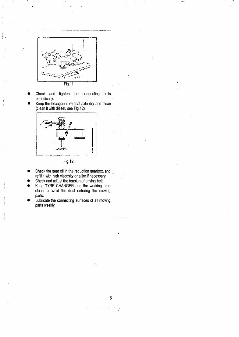
Fig.11
• Check and tighten the connecting boltsperiodically.
• Keep the hexagonal vertical axle dry and clean(clean it with diesel, see Flg.12).
Fig.12
• Check the gear oil in the reduction gearbox, and ..refill it with high viscosity or alike if necessary.
• Check and adjust the tension of driving belt.• Keep TYRE CHANGER and the working area
clean to avoid the dust entering the movingparts.
• Lubricate the connecting surfaces of all movingparts weekly.
5

l
Troubleshooting
Symptom Possible Cause Solution
The turntable rotates only in one + The reversing switch is + Replace the reserving switch.direction. damaged.The turntable does not rotate. + The belt is damaged. + Replace the belt.
� The reversing switch is • Replace the reserving switch.damaged. • Check the motor power, or
• The mbtor malfunctions . cable connection of the terminalblock.
+ Replace the motor if broken.+ The belt is too loose. + Adjust the belt tension. (Fig. 13)
The turntable cannot lock the rim. + The clamps are worn. + Replace the clamps.+ Sealing gasket on the + Replace the sealing gasket.
turntable is damaged.The pedal does not reset after + The spring is damaged. + Replace the spri�g.depressing.
Fig.13
6