Embed Size (px)
DESCRIPTION
TITAC: Design of a QDI microprocessor. TITAC: Tokyo Institute of Technology TITAC-1: IEEE Design & Test (Summer 94) 1. main goal: explore the design methodology 2. 8-bit Von Neumann microprocessor is designed TITAC-2: ICCD’97 32-bit fully functional - PowerPoint PPT Presentation
Citation preview

TITAC: Design of a QDI microprocessor
• TITAC: Tokyo Institute of Technology• TITAC-1: IEEE Design & Test (Summer 94) 1. main goal: explore the design methodology 2. 8-bit Von Neumann microprocessor is designed• TITAC-2: ICCD’97 32-bit fully functional microprocessor based on MIPS 2000
Reading 6

Outline
• Goal of TITAC-1• Organization and Instruction sets• Design methodology 1. control path 2. data path

Goal of TITAC-1
• Not to design a fully functional microprocessor but to explore the design methodology
A. determine suitable specification B. Implementation.
• Establish a library of building blocks for design automation of Async. VLSI systems.

Organization of TITAC
• TITAC is an 8-bit Von Neumann microprocessor• Single-accumulator architecture• TITAC consists of * Control section: 1. controls data flow of datapath section 2. two controllers: hardwired and
microprogrammed A. selectable by an external switch. B. designed by two authors independently. * Datapath section:

Organization of TITAC
• Datapath section: 1. An ALU (Arithmetic Logic Unit). 2. Instruction Register (IR) 3. One Accumulator (Acc) 4. Program Counter (PC) 5. Memory Address Register (MAR) 6. Input Buffer (In) 7. Output Buffer (Out) 8. Memory Interface (to Main Memory)• See Fig 1(TITAC organization) in pp. 53

TITAC’sOrganization

Instruction Set of TITAC
• Memory Reference Instructions: (two Bytes) A. opcode + operand B. address modes: 1. Immediate 2. Stack pointer relative 3. Indirect 4. Direct C. ADD mem ==> Acc := mem + Acc ADC mem: add with carry ...• Branch Instructions: (two bytes)• Miscellaneous Instructions: (one byte)

Instruction Set of TITAC

Protocol of TITAC
• Two phase, event-driven scheme: ( i.e. four-phase handshaking or return to zero) A: working phase: 1: working transient
2: working stable B: idle phase: 3: idle transient 4: idle stable

Specification: Data dependency graph
• High Performance ==> Execute as many micro-operations as possible. • Need to analyze dependency relations:• Use dependency graph to analyze micro-operations.• Five types of primitive elements: (see Fig 3) A. micro-operations: register to register data transfer B. fork: parallel execution threads C. join: synchronization of parallel execution D. select: condition branch. E. merge: merge signals.• Example: DDG of jmp instruction (Fig 4).

Five Basic Elements:

Data dependency graph: Jump
Write After Read
Write After Write

Implementation: dependency graph• Five types of primitive elements: (see Fig 3) A. micro-operations: Q-element (read + write). B. fork: fan-out wires C. join: Muller’s C element D. select: decoder (one out of n code) E. merge: EX-OR• Example: Fig 5.

Jump:
Control path Data path
Jump:
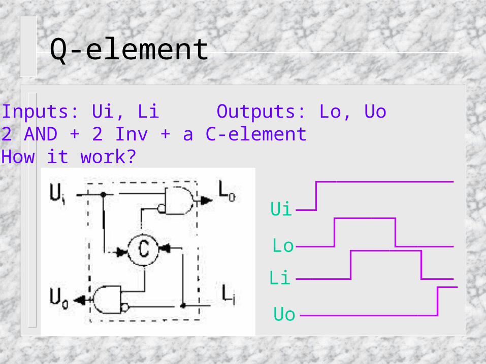
Q-element
• Inputs: Ui, Li Outputs: Lo, Uo• 2 AND + 2 Inv + a C-element• How it work?
Ui
Lo
Uo
Li

Performance Issue
• Performance problems:Need to reset (idle phase) the circuit.
• Solution: data analysis + Auto Sweeping Module

Auto Sweeping Module (ASM)
• Improve the latency.
Uo+ ==> start next computation ==> reset current computation
Parallel execution of working phase and idle phase
Ui
Lo
Uo
Li

Auto Sweeping Module (ASM)
• Replacement Q-element with ASM: A. replace each Q-element with one ASM. B. Analyze data dependency: WAW and WAR C. add AND gates to ensure the dependency.

ASM JUMP DDG

ASM JUMP Q JUMP

Microprogrammed Controller

Data Path Design
• Binary Decision Diagram (BDD) to implement combination logic such as ALU functions• For example: C BABAF

Data Path Design
• Binary Decision Diagram (BDD) to implement combination logic such as ALU functions• For example: C BABAF

Multiport Register
• Two port register:

• Two-port register:

Memory