Embed Size (px)
Citation preview

Titan Implement, LLC 3 6000 Series Moldboard Plows (423) 334-0012 January 2016
Pre-Delivery ChecklistThe Dealer should inform the Purchaser of this product of the Warranty terms, provisions, and procedures that are applicable. The Dealer and Purchaser should review the contents of the Operation and Parts Manual including safety equipment, safe operation and maintenance, review the Safety Signs on the implement (and tractor, if necessary), and the Purchaser’s responsibility to train their operators in correct operating procedures.
• MOUNTED IMPLEMENTS: I have explained that Defl ectors, Guards, or Shields must be installed and maintained in good repair, and that the operator is responsible for watching out for persons in the work area.
PRE-DELIVERY SERVICECHECK AND ADJUST AS REQUIRED
See Operation and Parts Manual for DetailsInspection Performed - Warranty and Safety Procedures Explained - Installation Complete
IMPLEMENT
Review Procedure to Adjust Plow
Make Sure All Hardware is Properly Tightened
ATTACHMENTS & INSTALLATION
Make Sure All Bolts, Pins, and Nuts are Properly Installed and Tightened
I have thoroughly instructed the purchaser on the above-described equipment. This review included the Operation and Parts Manual contents, equipment care, adjustments, safe operation, and applicable warranty policy.
Date__________________ Dealer Rep. Signature_________________________________________
The above equipment and Operation and Parts Manual have been received by me, and I have been thoroughly instructed as to equipment care, adjustments, safe operation, and applicable warranty policy.
Date__________________ Purchaser’s Signature_________________________________________
IMPLEMENT TO TRACTOR CONNECTIONS
Make Sure A-Frame Pivot and Links are Properly Installed
Make Sure Lift Arms are Adjusted Equally
Complete All Pre-Operation Checks
SAFETY ITEMS
Make Sure Protective Shields are Properly Installed
Review Operation and Parts Manual (Supplied)
Make Sure Tractor PTO Shield is Installed
Make Sure S.M.V. Sign is Installed, if Needed(Customer Supplied)
Cut
Her
e to
Rem
ove
Page
or M
ake
Cop
ies
of T
his
Page

Titan Implement, LLC 5 6000 Series Moldboard Plows (423) 334-0012 January 2016
1. Table of Contents
1. INTRODUCTION . . . . . . . . . . . . . . . . . . . . . . . . 61.1 Welcome . . . . . . . . . . . . . . . . . . . . . . . . . . . . . . 61.2 Safe Operation . . . . . . . . . . . . . . . . . . . . . . . . . 61.3 Specifi cations . . . . . . . . . . . . . . . . . . . . . . . . . . 71.4 Intended Usage . . . . . . . . . . . . . . . . . . . . . . . . . 71.5 Operator Orientation . . . . . . . . . . . . . . . . . . . . . 71.6 Serial Number Location (Typical) . . . . . . . . . . . 71.7 Product Improvements . . . . . . . . . . . . . . . . . . . 81.8 Disposal of Equipment at End of Useful Life . . . 81.9 Unanswered Questions . . . . . . . . . . . . . . . . . . . 8
2. SAFETY . . . . . . . . . . . . . . . . . . . . . . . . . . . . . . . 92.1 General . . . . . . . . . . . . . . . . . . . . . . . . . . . . . . . 92.2 Safety Alert Symbols . . . . . . . . . . . . . . . . . . . . . 92.3 Safety Icon Nomenclature . . . . . . . . . . . . . . . . 10
2.3.1 Personal Protection/Important Information . . . . . . . . . . . . . . . . . . . . . . 102.3.2 Prohibited Actions . . . . . . . . . . . . . . . . 102.3.3 Hazard Avoidance . . . . . . . . . . . . . . . . 10
2.4 General Safety Instruction. . . . . . . . . . . . . . . . 112.5 Training . . . . . . . . . . . . . . . . . . . . . . . . . . . . . . 122.6 OSHA Training Requirements . . . . . . . . . . . . . 122.7 Federal Laws and Regulations . . . . . . . . . . . . 132.8 Sign-Off Form . . . . . . . . . . . . . . . . . . . . . . . . . 142.9 Operation Safety . . . . . . . . . . . . . . . . . . . . . . . 152.10 Transporting Safety . . . . . . . . . . . . . . . . . . . . . 152.11 Storage Safety. . . . . . . . . . . . . . . . . . . . . . . . . 152.12 Maintenance Safety. . . . . . . . . . . . . . . . . . . . . 15
3. NOMENCLATURE . . . . . . . . . . . . . . . . . . . . . 16
4. OPERATION. . . . . . . . . . . . . . . . . . . . . . . . . . . 174.1 User Safety Training . . . . . . . . . . . . . . . . . . . . 174.2 Tractor Requirements . . . . . . . . . . . . . . . . . . . 18
4.2.1 Tractor Safety Devices. . . . . . . . . . . . . 184.2.2 ROPS and Seat Belt . . . . . . . . . . . . . . 184.2.3 Wheel Confi guration . . . . . . . . . . . . . . 184.2.4 3-Point Hitch . . . . . . . . . . . . . . . . . . . . 19
4.3 Attaching to Tractor . . . . . . . . . . . . . . . . . . . . 194.4 Setting the Moldboard Plow . . . . . . . . . . . . . . 20
4.4.1 Leveling the Frame . . . . . . . . . . . . . . . 204.4.2 Setting the Depth . . . . . . . . . . . . . . . . . 204.4.3 Setting the Width . . . . . . . . . . . . . . . . . 20
4.5 Optional Coulter Kit . . . . . . . . . . . . . . . . . . . . . 214.5.1 Coulter Adjustment. . . . . . . . . . . . . . . . 21
4.6 Optional Gauge Wheel Kit. . . . . . . . . . . . . . . . 214.6.1 Gauge Wheel Adjustment . . . . . . . . . . 21
4.7 Initial Setup Checklist . . . . . . . . . . . . . . . . . . . 224.8 Implement Break-In . . . . . . . . . . . . . . . . . . . . 224.9 General Operating Instructions . . . . . . . . . . . . 224.10 Detaching From Tractor . . . . . . . . . . . . . . . . . 23
5. TRANSPORTING. . . . . . . . . . . . . . . . . . . . . . . 245.1 Transporting Safety (Road) . . . . . . . . . . . . . . . 24
6. STORAGE. . . . . . . . . . . . . . . . . . . . . . . . . . . . . 256.1 Storage Safety. . . . . . . . . . . . . . . . . . . . . . . . . 256.2 Placing in Storage . . . . . . . . . . . . . . . . . . . . . . 256.3 Removing From Storage . . . . . . . . . . . . . . . . 25
7. SERVICE AND MAINTENANCE . . . . . . . . . . 267.1 Maintenance Safety. . . . . . . . . . . . . . . . . . . . . 267.2 Greasing . . . . . . . . . . . . . . . . . . . . . . . . . . . . . 277.3 Ground Engaging Components. . . . . . . . . . . . 27
7.3.1 Plow Share Replacement . . . . . . . . . . 277.3.2 Moldboard Replacement . . . . . . . . . . . 277.3.3 Skid Shoe Replacement . . . . . . . . . . . 27
7.4 Shear Bolt Replacement . . . . . . . . . . . . . . . . 287.5 Welding Repairs . . . . . . . . . . . . . . . . . . . . . . . 287.6 Bolt Torque Requirements. . . . . . . . . . . . . . . . 297.7 Service Record . . . . . . . . . . . . . . . . . . . . . . . . 30
8. TROUBLESHOOTING . . . . . . . . . . . . . . . . . . 31
9. WARRANTY . . . . . . . . . . . . . . . . . . . . . . . . . . 32
10. PARTS . . . . . . . . . . . . . . . . . . . . . . . . . . . . . . . 3510.1 Ground Engaging Components. . . . . . . . . . . . 3510.2 Plow Frame . . . . . . . . . . . . . . . . . . . . . . . . . . . 3610.3 A-Frame . . . . . . . . . . . . . . . . . . . . . . . . . . . . . 3710.4 Optional Coulter Kit . . . . . . . . . . . . . . . . . . . . . 3810.5 Optional Gauge Wheel Kit. . . . . . . . . . . . . . . . 39
6000 Series Moldboard Plows 6 Titan Implement, LLC January 2016 (423) 334-0012
2. INTRODUCTION
2.1 Welcome
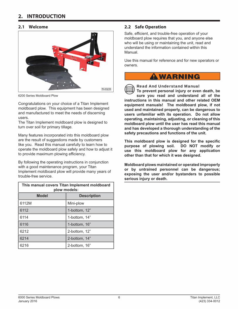
6200 Series Moldboard Plow
Congratulations on your choice of a Titan Implement moldboard plow. This equipment has been designed and manufactured to meet the needs of discerning users.The Titan Implement moldboard plow is designed to turn over soil for primary tillage.
Many features incorporated into this moldboard plow are the result of suggestions made by customers like you. Read this manual carefully to learn how to operate the moldboard plow safely and how to adjust it to provide maximum plowing effi ciency.
By following the operating instructions in conjunction with a good maintenance program, your Titan Implement moldboard plow will provide many years of trouble-free service.
This manual covers Titan Implement moldboard plow models:
Model Description
6112M Mini-plow
6112 1-bottom, 12”
6114 1-bottom, 14”
6116 1-bottom, 16”
6212 2-bottom, 12”
6214 2-bottom, 14”
6216 2-bottom, 16”
2.2 Safe Operation
Safe, effi cient, and trouble-free operation of your moldboard plow requires that you, and anyone else who will be using or maintaining the unit, read and understand the information contained within this Manual.
Use this manual for reference and for new operators or owners.
WARNINGRead And Understand Manual To prevent personal injury or even death, be sure you read and understand all of the
instructions in this manual and other related OEM equipment manuals! The moldboard plow, if not used and maintained properly, can be dangerous to users unfamiliar with its operation. Do not allow operating, maintaining, adjusting, or cleaning of this moldboard plow until the user has read this manual and has developed a thorough understanding of the safety precautions and functions of the unit.
This moldboard plow is designed for the specifi c purpose of plowing soil. DO NOT modify or use this moldboard plow for any application other than that for which it was designed.
Moldboard plows maintained or operated improperly or by untrained personnel can be dangerous; exposing the user and/or bystanders to possible serious injury or death.
Titan Implement, LLC 7 6000 Series Moldboard Plows (423) 334-0012 January 2016
2.3 Specifications
One Bottom
Model 6112M 6112 6114 6116
HorsepowerRequired 18 18 22 25
Hitch CAT lPlowshare Width 12” 14” 16”
Two Bottom
Model 6212 6214 6216
HorsepowerRequired 36 44 50
Hitch CAT lPlowshare Width 12” 14” 16”
Specifi cations subject to change without notice.
2.4 Intended Usage
Do not use this moldboard plow for any other purpose than its intended use of plowing soil.
2.5 Operator Orientation
The directions left, right, front, and rear, as mentioned throughout this manual, are as seen from the tractor operator’s seat and facing in the direction of travel.
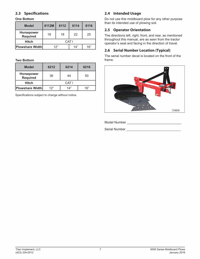
2.6 Serial Number Location (Typical)
The serial number decal is located on the front of the frame.
Model Number ______________________________
Serial Number ______________________________
6000 Series Moldboard Plows 8 Titan Implement, LLC January 2016 (423) 334-0012
2.7 Product Improvements
Because Titan Implement, LLC maintains an ongoing program of product improvement, we reserve the right to make improvements in design or changes in specifi cations without incurring any obligation to install them on units previously sold.
2.8 Disposal of Equipment at End of Useful Life
The Titan Implement, LLC moldboard plow has been designed for the specifi c purpose of plowing soil. When this unit is no longer capable of doing its designed purpose, it should be dismantled and scrapped. Do not use any materials or components from this unit for any other purpose.
2.9 Unanswered Questions
If you have any questions not answered in this manual, require additional copies, or the manual is damaged, please contact your dealer or:
Titan Implement, LLCP.O. Box 649232 Industrial LaneDecatur, TN 37322
Phone: (423) 334-0012Fax: (423) 334-0023
The manual is also available for download at: www.titanimplement.com
1. Select “Products”.
2. Select “Moldboard Plows”.
3. Click the “Specs., Manuals, Warranty” tab.
4. Click “Download Manual”.
Titan Implement, LLC 9 6000 Series Moldboard Plows (423) 334-0012 January 2016
3. Safety
3.1 General
Safety of the operator and bystanders is one of the main concerns in designing and developing a new piece of equipment. Designers and manufacturers build in as many safety features as possible. However, every year many accidents occur which could have been avoided by a few seconds of thought and a more careful approach to handling the equipment.
Most work-related accidents are caused by failure to observe basic safety rules or precautions. An accident can often be avoided by recognizing potentially hazardous situations before an accident occurs. As you assemble, operate, or maintain the moldboard plow (unit), you must be alert to potential hazards. You should also have the necessary training, skills, and tools to perform any assembly or maintenance procedures.
Improper operation and maintenance of this unit could result in a dangerous situation that could cause injury or death.
If you have any questions not answered in this manual or require additional copies or the manual is damaged, please contact your dealer or:Titan Implement, LLC P.O. Box 649232 Industrial LaneDecatur, TN 37322 Phone: (423) 334-0012Fax: (423) 334-0023
WARNINGDo not assemble, operate, or maintain the unit until you read and understand the information contained in this manual.
Safety precautions and warnings are provided in this manual. If these hazard warnings are not heeded, bodily injury or death could occur
to you or to other persons.
Titan Implement, LLC cannot anticipate every possible circumstance that might involve a potential hazard. The warnings in this manual are, therefore, not all-inclusive. If a method of assembly, operation, or maintenance not specifi cally recommended by us is used, you must satisfy yourself that it is safe for you and for others. You should also ensure that the unit will not be damaged or be made unsafe by the methods that you choose.
The information, specifi cations, and illustrations in this manual are based on the information that was available at the time this material was written and can change at any time without notice.
3.2 Safety Alert Symbols
This is the safety alert symbol. It is used to alert you to potential personal injury hazards. Obey all safety messages that follow this symbol to avoid possible injury or death.
This manual contains DANGERS, SAFETY INSTRUCTIONS, CAUTIONS, IMPORTANT NOTICES, and NOTES which must be followed to prevent the possibility of improper service, damage to the equipment, personal injury, or death. The following key words call the readers’ attention to potential hazards.
Hazards are identifi ed by the “Safety Alert Symbol” and followed by a signal word such as “DANGER”, “WARNING”, or “CAUTION”.
DANGERIndicates an imminently hazardous situation which, if not avoided, will result in death or serious injury. This signal word is limited to the most extreme situations.
WARNINGIndicates a potentially hazardous situation which, if not avoided, could result in death or serious injury.
CAUTIONIndicates a potentially hazardous situation which, if not avoided, may result in minor or moderate injury.
NOTICEIndicates that equipment or property damage can result if instructions are not followed.
SAFETYINSTRUCTIONS
Safety instructions (or equivalent) signs indicate specifi c safety-related instructions or procedures.
Note: Contains additional information important to a procedure.
6000 Series Moldboard Plows 10 Titan Implement, LLC January 2016 (423) 334-0012
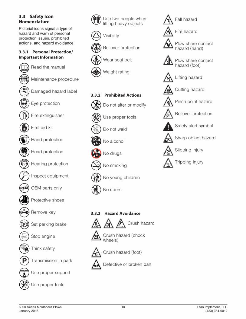
3.3 Safety Icon Nomenclature
Pictorial icons signal a type of hazard and warn of personal protection issues, prohibited actions, and hazard avoidance.
3.3.1 Personal Protection/
Important Information
Read the manual
Maintenance procedure
N INGAR
Damaged hazard label
Eye protection
Fire extinguisher
First aid kit
Hand protection
Head protection
Hearing protection
Inspect equipment
OEMOEM OEM parts only
Protective shoes
Remove key
Set parking brake
STOP Stop engine
THINKSAFETY! Think safety
Transmission in park
Use proper support
Use proper tools
Use two people when lifting heavy objects
Visibility
Rollover protection
Wear seat belt
Weight rating
3.3.2 Prohibited Actions
Do not alter or modify
Use proper tools
Do not weld
No alcohol
No drugs
No smoking
No young children
No riders
3.3.3 Hazard Avoidance
Crush hazard
Crush hazard (chock wheels)
Crush hazard (foot)
Defective or broken part
Fall hazard
Fire hazard
Plow share contact hazard (hand)
Plow share contact hazard (foot)
Lifting hazard
Cutting hazard
Pinch point hazard
Rollover protection
Safety alert symbol
Sharp object hazard
Slipping injury
Tripping injury
Titan Implement, LLC 11 6000 Series Moldboard Plows (423) 334-0012 January 2016
3.4 General Safety Instruction
The owner/operator is responsible for the SAFE use and maintenance of the moldboard plow. Make sure anyone who is operating, maintaining, or working around the moldboard plow is familiar with the operating and maintenance procedures and related SAFETY information contained in this manual. This manual will take you step-by-step through your working day and alerts you to all good safety practices that should be used while using the moldboard plow.
In addition to the design features of the moldboard plow, including safety signs, accident prevention is dependent upon the awareness, concern, prudence, and proper training of the people involved in the operation, maintenance, and storage of the moldboard plow.
In addition to this safety section, refer also to safety messages and instructions in each of the appropriate sections of this manual.
These general safety instructions apply to the overall use and maintenance of the moldboard plow.
More specifi c instructions on safety are found in the operation, maintenance, and storage sections of this manual. Refer to these sections before performing any of these tasks.
WARNINGFailure to comply with the following safety instructions could result in serious injury and possibly even death.
Provide User with Literature Titan Implement, LLC moldboard plow owners must provide operator instructions to
anyone using the moldboard plow before use, and at least annually thereafter. Refer to “3.6 OSHA Training Requirements” on page 12.
Stay Clear Clear the area of people, especially small children, before using the moldboard plow.
Under no circumstances should young children be allowed to work with or around the moldboard plow.
Impaired User Hazard Do not attempt to assemble, operate, or maintain this moldboard plow under
the infl uence of drugs or alcohol. Consult your doctor before using this moldboard plow while taking prescription medications.
WARNINGCrush Hazard Do not allow anyone to ride on the tractor or the moldboard plow. Falling
or crushing hazards can result in severe injuries or death.
Damaged Parts Hazard Do not use the moldboard plow if any parts are damaged. If the moldboard plow has a
defect, immediately stop using it and remedy the problem before continuing.
CAUTIONThe following safety instructions are provided to help prevent potential injury. Not following these instructions could result in minor to moderate injury.
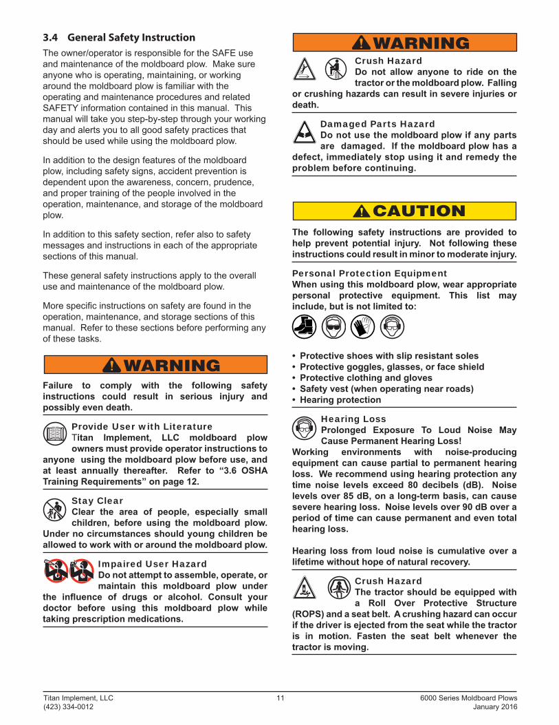
Personal Protection Equipment When using this moldboard plow, wear appropriate personal protective equipment. This list may include, but is not limited to:
• Protective shoes with slip resistant soles • Protective goggles, glasses, or face shield • Protective clothing and gloves • Safety vest (when operating near roads) • Hearing protection
Hearing Loss Prolonged Exposure To Loud Noise May Cause Permanent Hearing Loss!
Working environments with noise-producing equipment can cause partial to permanent hearing loss. We recommend using hearing protection any time noise levels exceed 80 decibels (dB). Noise levels over 85 dB, on a long-term basis, can cause severe hearing loss. Noise levels over 90 dB over a period of time can cause permanent and even total hearing loss.
Hearing loss from loud noise is cumulative over a lifetime without hope of natural recovery.
Crush Hazard The tractor should be equipped with a Roll Over Protective Structure
(ROPS) and a seat belt. A crushing hazard can occur if the driver is ejected from the seat while the tractor is in motion. Fasten the seat belt whenever the tractor is moving.
6000 Series Moldboard Plows 12 Titan Implement, LLC January 2016 (423) 334-0012
SAFETYINSTRUCTIONS
The following safety instructions are provided to help prevent injury or limit equipment damage.
First Aid Kit Have a fi rst aid kit available for use should the need arise and know how to use it.
Fire Extinguisher Have a fi re extinguisher available for use should the need arise and know how to use it.
THINKSAFETY! Think SAFETY!
Work SAFELY!
3.5 Training
Anyone who will be using and/or maintaining the moldboard plow must read, clearly understand, and follow ALL safety, operation, and maintenance information presented in this manual and other related OEM manuals.
If you do not understand any information in this manual, see your dealer or contact Titan Implement before proceeding.
Do not use or allow anyone else to use this moldboard plow until all information has been reviewed. Annually review this manual before the season start-up.
Make periodic reviews of SAFETY and OPERATION of the moldboard plow a standard practice. An untrained operator is not qualifi ed to use this moldboard plow.
3.6 OSHA Training Requirements
The following training requirements have been taken from Title 29, Code of Federal Regulations Part 1928.57 (a) (6). www.osha.gov.
Operator instructions. At the time of initial assignment and at least annually thereafter, the employer shall instruct every employee who operates an agricultural tractor and implements in the safe operating practices and servicing of equipment with which they are or will be involved, and of any other practices dictated by the work environment.
Titan Implement, LLC 13 6000 Series Moldboard Plows (423) 334-0012 January 2016
3.7 Federal Laws and Regulations
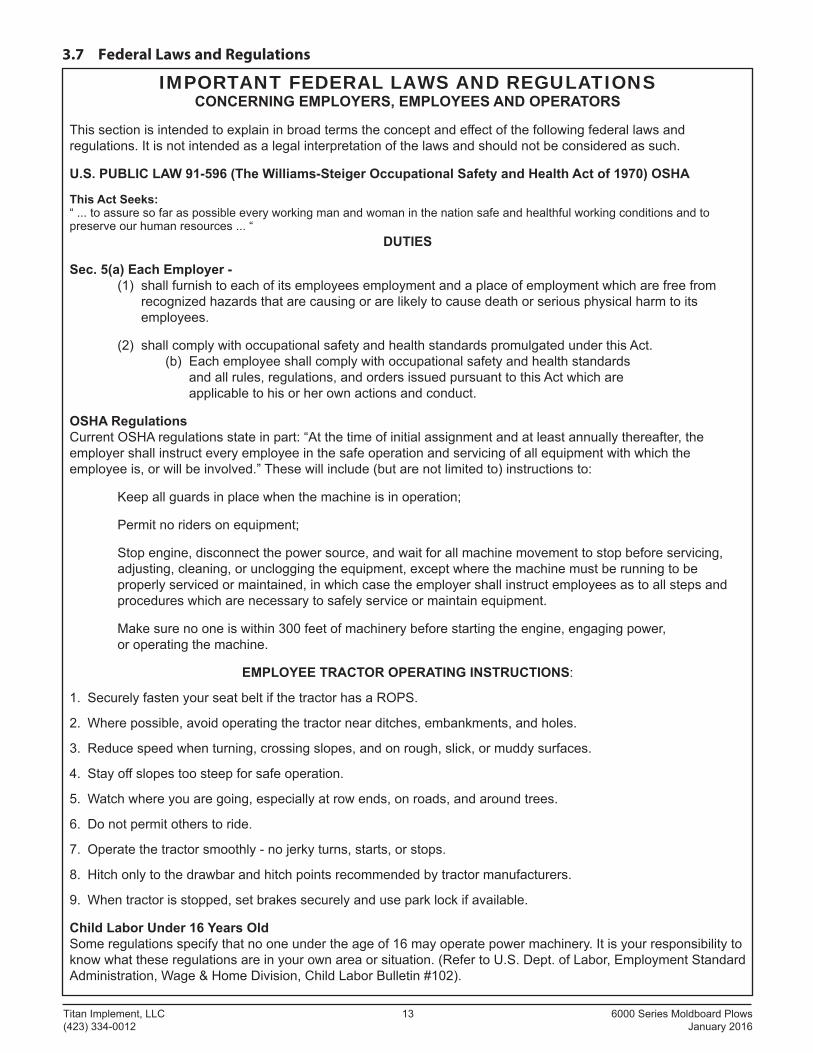
IMPORTANT FEDERAL LAWS AND REGULATIONS CONCERNING EMPLOYERS, EMPLOYEES AND OPERATORS
This section is intended to explain in broad terms the concept and eff ect of the following federal laws and regulations. It is not intended as a legal interpretation of the laws and should not be considered as such.
U.S. PUBLIC LAW 91-596 (The Williams-Steiger Occupational Safety and Health Act of 1970) OSHA
This Act Seeks:“ ... to assure so far as possible every working man and woman in the nation safe and healthful working conditions and to preserve our human resources ... “
DUTIES
Sec. 5(a) Each Employer - (1) shall furnish to each of its employees employment and a place of employment which are free from
recognized hazards that are causing or are likely to cause death or serious physical harm to its employees.
(2) shall comply with occupational safety and health standards promulgated under this Act. (b) Each employee shall comply with occupational safety and health standards
and all rules, regulations, and orders issued pursuant to this Act which areapplicable to his or her own actions and conduct.
OSHA RegulationsCurrent OSHA regulations state in part: “At the time of initial assignment and at least annually thereafter, the employer shall instruct every employee in the safe operation and servicing of all equipment with which the employee is, or will be involved.” These will include (but are not limited to) instructions to:
Keep all guards in place when the machine is in operation;
Permit no riders on equipment;
Stop engine, disconnect the power source, and wait for all machine movement to stop before servicing,adjusting, cleaning, or unclogging the equipment, except where the machine must be running to beproperly serviced or maintained, in which case the employer shall instruct employees as to all steps andprocedures which are necessary to safely service or maintain equipment.
Make sure no one is within 300 feet of machinery before starting the engine, engaging power,or operating the machine.
EMPLOYEE TRACTOR OPERATING INSTRUCTIONS:
1. Securely fasten your seat belt if the tractor has a ROPS.
2. Where possible, avoid operating the tractor near ditches, embankments, and holes.
3. Reduce speed when turning, crossing slopes, and on rough, slick, or muddy surfaces.
4. Stay off slopes too steep for safe operation.
5. Watch where you are going, especially at row ends, on roads, and around trees.
6. Do not permit others to ride.
7. Operate the tractor smoothly - no jerky turns, starts, or stops.
8. Hitch only to the drawbar and hitch points recommended by tractor manufacturers.
9. When tractor is stopped, set brakes securely and use park lock if available.
Child Labor Under 16 Years OldSome regulations specify that no one under the age of 16 may operate power machinery. It is your responsibility to know what these regulations are in your own area or situation. (Refer to U.S. Dept. of Labor, Employment Standard Administration, Wage & Home Division, Child Labor Bulletin #102).
6000 Series Moldboard Plows 14 Titan Implement, LLC January 2016 (423) 334-0012
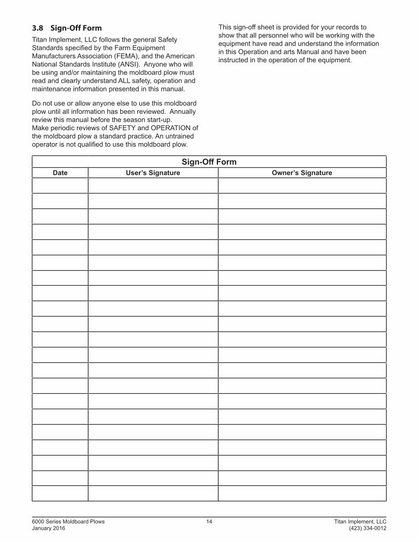
3.8 Sign-Off Form
Titan Implement, LLC follows the general Safety Standards specifi ed by the Farm Equipment Manufacturers Association (FEMA), and the American National Standards Institute (ANSI). Anyone who will be using and/or maintaining the moldboard plow must read and clearly understand ALL safety, operation and maintenance information presented in this manual.
Do not use or allow anyone else to use this moldboard plow until all information has been reviewed. Annually review this manual before the season start-up. Make periodic reviews of SAFETY and OPERATION of the moldboard plow a standard practice. An untrained operator is not qualifi ed to use this moldboard plow.
Sign-Off FormDate User’s Signature Owner’s Signature
This sign-off sheet is provided for your records to show that all personnel who will be working with the equipment have read and understand the information in this Operation and arts Manual and have been instructed in the operation of the equipment.
Titan Implement, LLC 15 6000 Series Moldboard Plows (423) 334-0012 January 2016
3.9 Operation Safety
Refer to “5.1 User Safety Training” on page 17 for safety recommendations related to using the moldboard plow. All applicable safety recommendations in other sections should also be followed.
3.10 Transporting Safety
Refer to “6.1 Transporting Safety (Road)” on page 24 for safety recommendations related to transporting the moldboard plow. All applicable safety recommendations in other sections should also be followed.
3.11 Storage Safety
Refer to “7.1 Storage Safety” on page 25 for safety recommendations related to storing the moldboard plow. All applicable safety recommendations in other sections should also be followed.
3.12 Maintenance Safety
Refer to “8.1 Maintenance Safety” on page 26 for safety recommendations related to maintaining the moldboard plow. All applicable safety recommendations in other sections should also be followed.
6000 Series Moldboard Plows 16 Titan Implement, LLC January 2016 (423) 334-0012
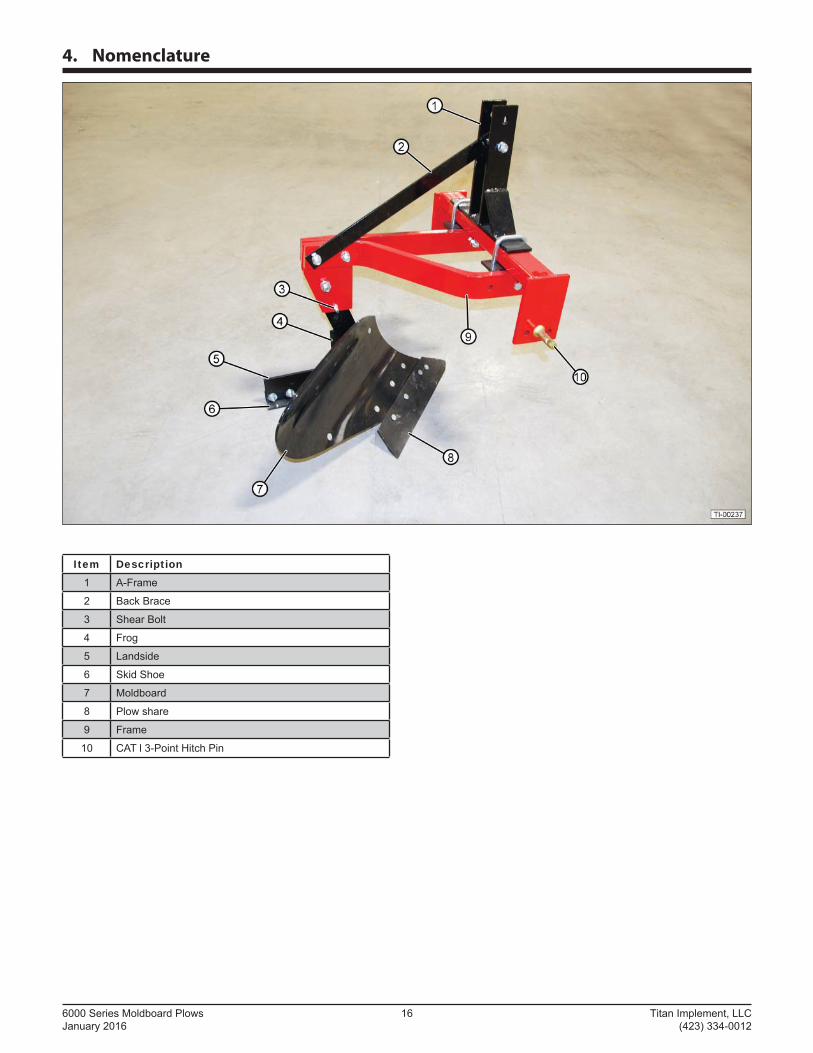
4. Nomenclature
Item Description1 A-Frame
2 Back Brace
3 Shear Bolt
4 Frog
5 Landside
6 Skid Shoe
7 Moldboard
8 Plow share
9 Frame
10 CAT l 3-Point Hitch Pin
Titan Implement, LLC 17 6000 Series Moldboard Plows (423) 334-0012 January 2016
5. Operation
5.1 User Safety Training
Refer to “3.4 General Safety Instruction” on page 11 for general user safety training requirements.
WARNINGSTOP
Roll Away Hazard Before leaving the tractor seat, make sure
the engine is stopped, the transmission is placed in park, the key is removed, and the parking brake is set.
The weight of the tractor, plus the implement, if it rolls onto a person, can cause serious crushing injury or death.
Crush Hazard The tractor should be equipped with a Roll Over Protective Structure
(ROPS) and a seat belt. A crushing hazard can occur if the driver is ejected from the seat while the tractor is in motion. Fasten the seat belt whenever the tractor is moving.
Call 811 To avoid serious injury or death from contacting underground utilities, call local
utilities to mark the location of all underground cables, pipelines, and other hazards in the area.
Stay Clear Clear the work area of all unnecessary people and obstructions to prevent personal injury.
Moldboard Plow Contact Hazard (hand) To avoid serious injury or death, keep away from ground-engaging components. Do
not put hands under moldboard plow.
Moldboard Plow Contact Hazard (foot) To avoid serious injury or death, keep away from ground engaging components. Do not
put feet under moldboard plow.
SAFETYINSTRUCTIONS
The following safety instructions are provided to help prevent injury or limit equipment damage.
THINKSAFETY!
Train Unfamiliar Users It is the moldboard plow owner’s responsibility to make sure any person
using the moldboard plow, especially if it is loaned or rented, has been thoroughly trained on its proper and safe use.
Be certain only physically-able persons will use the moldboard plow.
Untrained users expose themselves and bystanders to possible serious injury or death.
If the elderly are assisting with the work, their physical limitations need to be recognized and accommodated.
Never allow children to operate equipment.
6000 Series Moldboard Plows 18 Titan Implement, LLC January 2016 (423) 334-0012
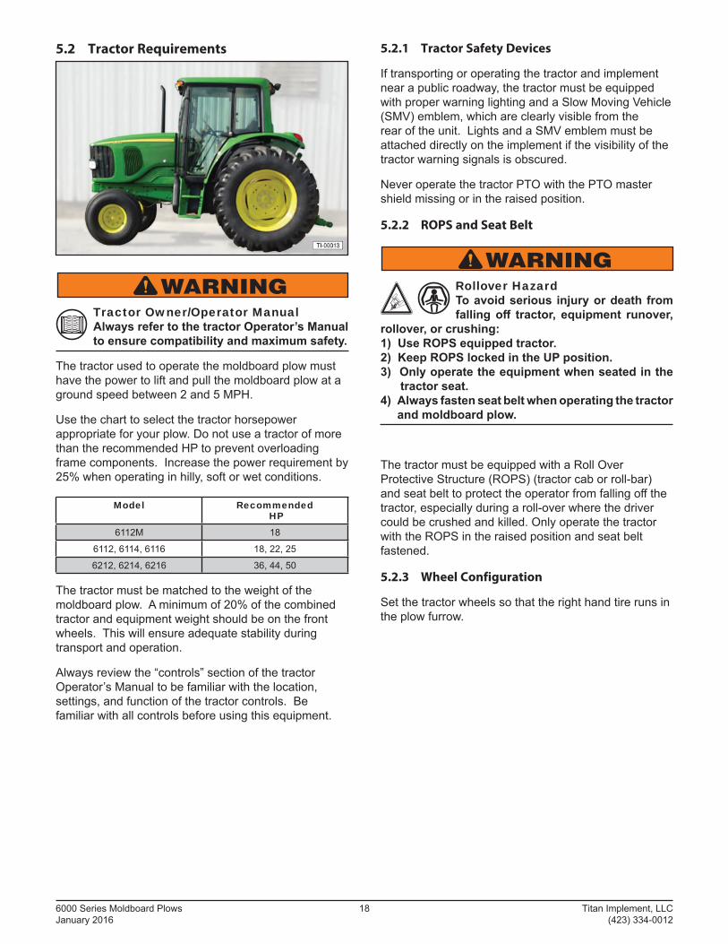
5.2 Tractor Requirements
WARNINGTractor Owner/Operator Manual Always refer to the tractor Operator’s Manual to ensure compatibility and maximum safety.
The tractor used to operate the moldboard plow must have the power to lift and pull the moldboard plow at a ground speed between 2 and 5 MPH.
Use the chart to select the tractor horsepower appropriate for your plow. Do not use a tractor of more than the recom mended HP to prevent overloading frame components. Increase the power requirement by 25% when operating in hilly, soft or wet conditions.
Model Recommended HP
6112M 18
6112, 6114, 6116 18, 22, 25
6212, 6214, 6216 36, 44, 50
The tractor must be matched to the weight of the moldboard plow. A minimum of 20% of the combined tractor and equipment weight should be on the front wheels. This will ensure adequate stability during transport and operation.
Always review the “controls” section of the tractor Operator’s Manual to be familiar with the location, settings, and function of the tractor controls. Be familiar with all controls before using this equipment.
5.2.1 Tractor Safety Devices
If transporting or operating the tractor and implement near a public roadway, the tractor must be equipped with proper warning lighting and a Slow Moving Vehicle (SMV) emblem, which are clearly visible from the rear of the unit. Lights and a SMV emblem must be attached directly on the implement if the visibility of the tractor warning signals is obscured.
Never operate the tractor PTO with the PTO master shield missing or in the raised position.
5.2.2 ROPS and Seat Belt
WARNINGRollover Hazard To avoid serious injury or death from falling off tractor, equipment runover,
rollover, or crushing: 1) Use ROPS equipped tractor. 2) Keep ROPS locked in the UP position. 3) Only operate the equipment when seated in the tractor seat. 4) Always fasten seat belt when operating the tractor
and moldboard plow.
The tractor must be equipped with a Roll Over Protective Structure (ROPS) (tractor cab or roll-bar) and seat belt to protect the operator from falling off the tractor, especially during a roll-over where the driver could be crushed and killed. Only operate the tractor with the ROPS in the raised position and seat belt fastened.
5.2.3 Wheel Configuration
Set the tractor wheels so that the right hand tire runs in the plow furrow.
Titan Implement, LLC 19 6000 Series Moldboard Plows (423) 334-0012 January 2016
5.2.4 3-Point Hitch
These moldboard plows are designed to be mounted on a tractor CAT I 3-Point or Quick Hitch.
Refer to the tractor operator’s manual for the category of the tractor being used. If the hitch does not conform to ASABE CAT I dimensions, the plow may not fi t or raise properly. Consult an authorized dealer for possible modifi cation procedures to mount non-conforming hitches. Depending on the hitch category, certain size pins are used to attach the implement to the tractor. CAT I hitches require 7/8” lower and 3/4” upper diameter hitch pins.
Always set the 3-point hitch in the “fl oat” mode to allow the plow to follow the contour of the ground.
Many newer tractors are equipped with “load Sensing” hydraulics. It is the responsibility of the operator to set the tractor hydraulic system to provide ‘’fl oat” on the 3-point hitch. Refer to the tractor Operator’s Manual for details.
Install the lift arm stabilizer or shorten the stop chains to place the arms into the non-sway con fi guration. Refer to the tractor manual for details.
Always install weights on the front of the tractor to provide extra stability and traction. This is particularly important if your tractor is equipped with a front wheel assist option.
5.3 Attaching to Tractor
Use caution when connecting the moldboard plow to the tractor. The moldboard plow should be securely resting on the ground or setting on blocks. Keep hands and feet from under the plow and clear of pinch points between the tractor hitch arms and moldboard plow hitch pins.
WARNING Crush Hazard Do not allow anyone to stand between the hitch and implement during hook-up operations. Never operate the hydraulic 3-point lift controls while someone is directly behind the tractor.
1. Shorten or remove the tractor drawbar to avoid interference when raising and lowering the moldboard plow.
2. Board the tractor and start the engine. Position the tractor with the 3-point lift arms positioned at the same height and to the outside of the moldboard plow hitch pins.
Note: Set the 3-point lift control to “Position Control” so that the lift arms maintain a constant height when attaching the moldboard plow. See the tractor Operator’s Manual for correct settings when attaching 3-point equipment.
3. Turn off the tractor engine and dismount.
4. One lift arm at a time, insert hitch pin through the lift arm holes and install retaining pin.
5. Walk around to the opposite side and repeat the procedure for the remaining lift arm and hitch pin.
6. Extend or retract 3-point top link to align its end hole with the hole of the moldboard plow’s top link. Insert the top link hitch pin and insert the retaining pin into the hitch pin.
7. Adjust any lower link check chains, guide blocks, or sway blocks to prevent the moldboard plow from swaying side-to-side and possible contact with the tractor rear tires.
6000 Series Moldboard Plows 20 Titan Implement, LLC January 2016 (423) 334-0012
5.4 Setting the Moldboard Plow
Properly setting the plow is essential for effi cient and safe operation. A properly adjusted moldboard plow will make a more uniform furrow, turn over the soil more evenly, require minimal tractor work, and follow the contour of uneven terrain.
5.4.1 Leveling the Frame
1. Use the screw jack on the right lift arm to level the frame from side-to-side. The cross frame should be level when the plow is in working position with the right tractor tire in the furrow.
2. Use the turnbuckle on the top link to level the frame from front to back. The frame should be parallel to the ground when the plow is at working depth.
3. Place the 3 point hitch in “fl oat” operating mode to allow the machine and the hitch to move up and down as required to follow ground contours.
5.4.2 Setting the Depth
The plow point pitch is controlled by the 3-point hitch top turnbuckle link. Shortening the upper link will increase the depth. Lengthening the upper link will decrease the depth.
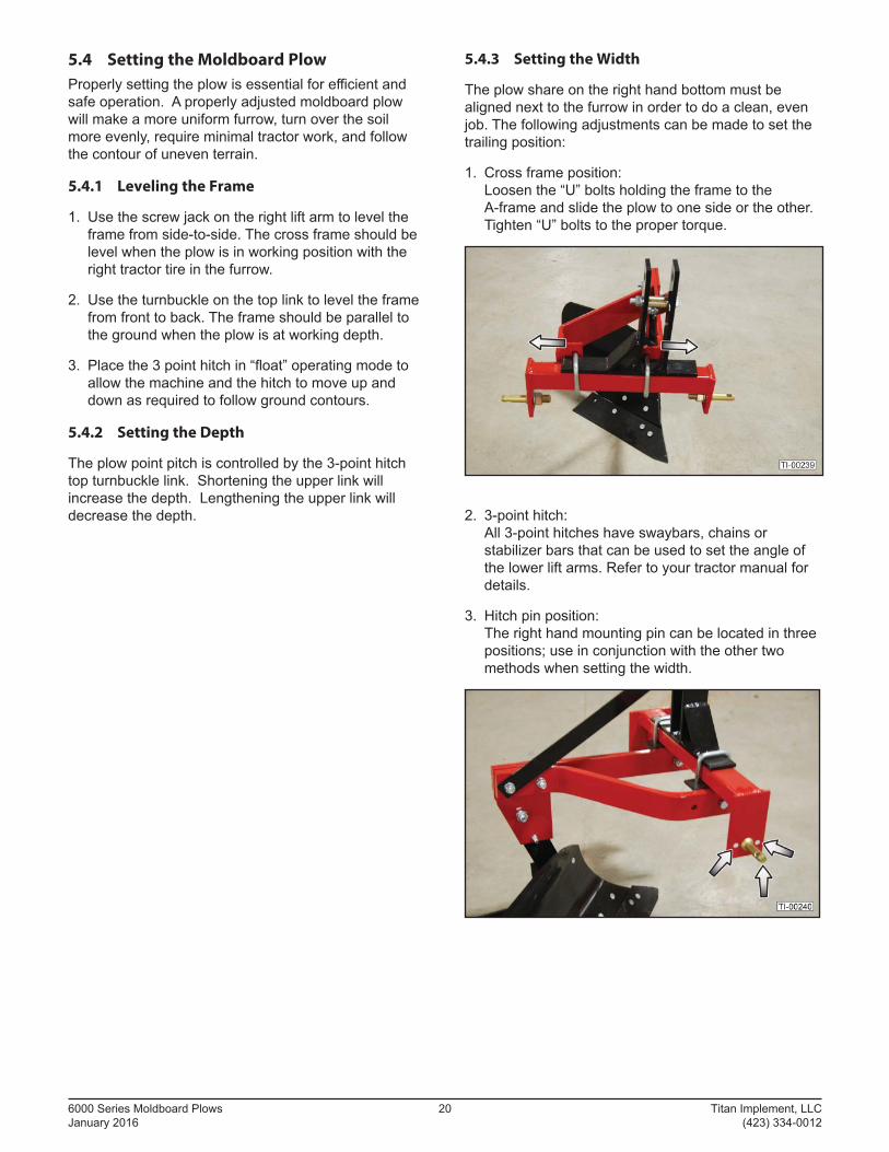
5.4.3 Setting the Width
The plow share on the right hand bottom must be aligned next to the furrow in order to do a clean, even job. The following adjustments can be made to set the trailing position:
1. Cross frame position:Loosen the “U” bolts holding the frame to the A-frame and slide the plow to one side or the other. Tighten “U” bolts to the proper torque.
2. 3-point hitch:All 3-point hitches have swaybars, chains or stabilizer bars that can be used to set the angle of the lower lift arms. Refer to your tractor manual for details.
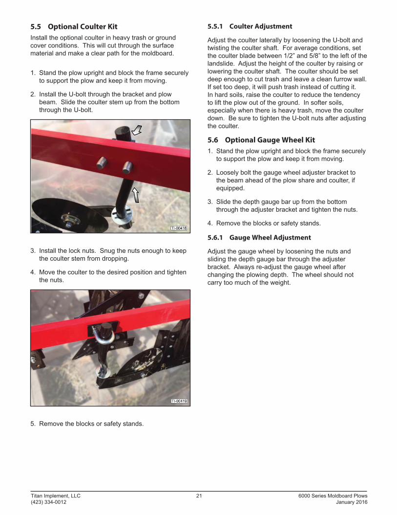
3. Hitch pin position:The right hand mounting pin can be located in three positions; use in con junction with the other two methods when setting the width.
Titan Implement, LLC 21 6000 Series Moldboard Plows (423) 334-0012 January 2016
5.5 Optional Coulter Kit
Install the optional coulter in heavy trash or ground cover conditions. This will cut through the surface material and make a clear path for the moldboard.
1. Stand the plow upright and block the frame securely to support the plow and keep it from moving.
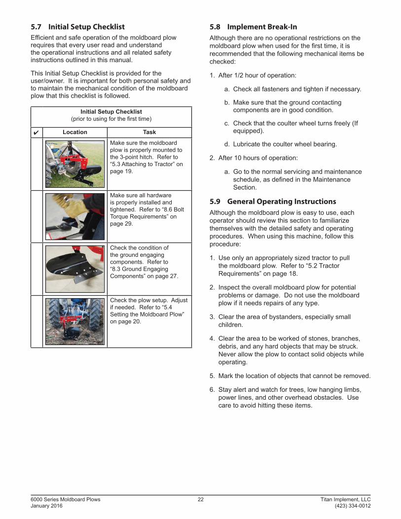
2. Install the U-bolt through the bracket and plow beam. Slide the coulter stem up from the bottom through the U-bolt.
3. Install the lock nuts. Snug the nuts enough to keep the coulter stem from dropping.
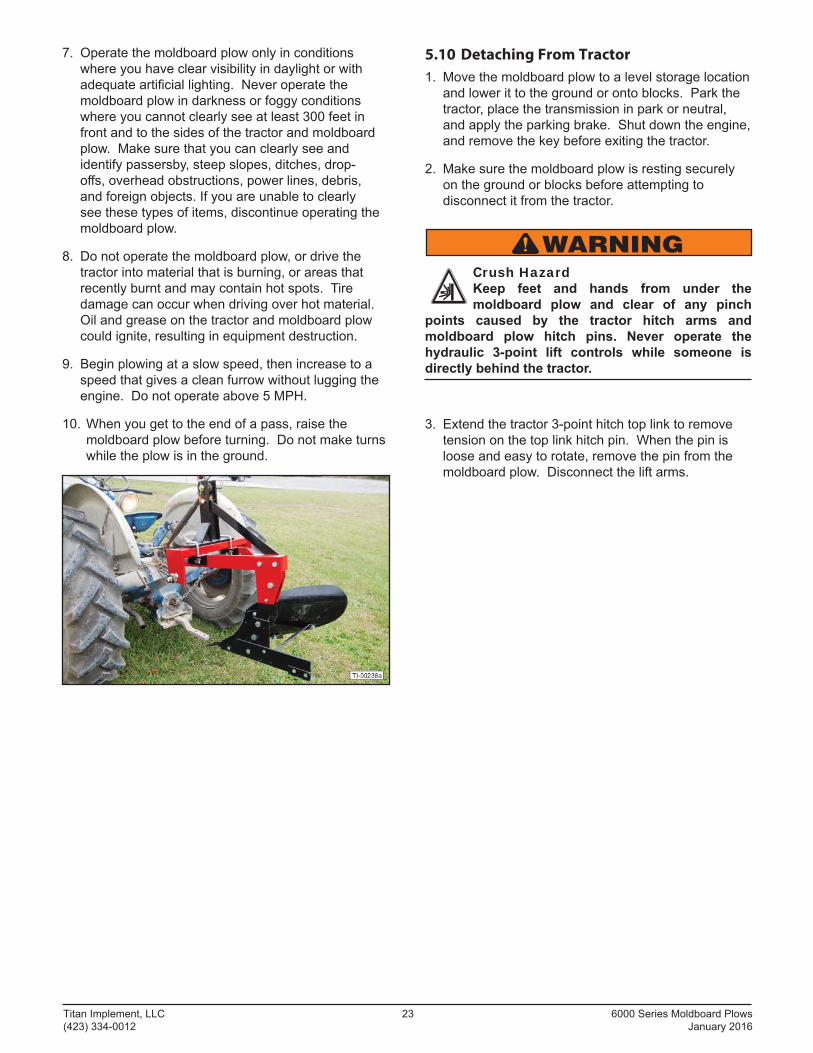
4. Move the coulter to the desired position and tighten the nuts.
5. Remove the blocks or safety stands.
5.5.1 Coulter Adjustment
Adjust the coulter laterally by loosening the U-bolt and twisting the coulter shaft. For average conditions, set the coulter blade between 1/2” and 5/8” to the left of the landslide. Adjust the height of the coulter by raising or lowering the coulter shaft. The coulter should be set deep enough to cut trash and leave a clean furrow wall. If set too deep, it will push trash instead of cutting it.In hard soils, raise the coulter to reduce the tendency to lift the plow out of the ground. In softer soils, especially when there is heavy trash, move the coulter down. Be sure to tighten the U-bolt nuts after adjusting the coulter.
5.6 Optional Gauge Wheel Kit
1. Stand the plow upright and block the frame securely to support the plow and keep it from moving.
2. Loosely bolt the gauge wheel adjuster bracket to the beam ahead of the plow share and coulter, if equipped.
3. Slide the depth gauge bar up from the bottom through the adjuster bracket and tighten the nuts.
4. Remove the blocks or safety stands.
5.6.1 Gauge Wheel Adjustment
Adjust the gauge wheel by loosening the nuts and sliding the depth gauge bar through the adjuster bracket. Always re-adjust the gauge wheel after changing the plowing depth. The wheel should not carry too much of the weight.
6000 Series Moldboard Plows 22 Titan Implement, LLC January 2016 (423) 334-0012
5.7 Initial Setup Checklist
Effi cient and safe operation of the moldboard plow requires that every user read and understand the operational instructions and all related safety instructions outlined in this manual.
This Initial Setup Checklist is provided for the user/owner. It is important for both personal safety and to maintain the mechanical condition of the moldboard plow that this checklist is followed.
Initial Setup Checklist (prior to using for the fi rst time)
✔ Location Task
Make sure the moldboard plow is properly mounted to the 3-point hitch. Refer to “5.3 Attaching to Tractor” on page 19.
Make sure all hardware is properly installed and tightened. Refer to “8.6 Bolt Torque Requirements” on page 29.
Check the condition of the ground engaging components. Refer to “8.3 Ground Engaging Components” on page 27.
Check the plow setup. Adjust if needed. Refer to “5.4 Setting the Moldboard Plow” on page 20.
5.8 Implement Break-In
Although there are no operational restrictions on the moldboard plow when used for the fi rst time, it is recommended that the following mechanical items be checked:
1. After 1/2 hour of operation:
a. Check all fasteners and tighten if necessary.
b. Make sure that the ground contacting components are in good condition.
c. Check that the coulter wheel turns freely (If equipped).
d. Lubricate the coulter wheel bearing.
2. After 10 hours of operation:
a. Go to the normal servicing and maintenance schedule, as defi ned in the Maintenance Section.
5.9 General Operating Instructions
Although the moldboard plow is easy to use, each operator should review this section to familiarize themselves with the detailed safety and operating procedures. When using this machine, follow this procedure:
1. Use only an appropriately sized tractor to pull the moldboard plow. Refer to “5.2 Tractor Requirements” on page 18.
2. Inspect the overall moldboard plow for potential problems or damage. Do not use the moldboard plow if it needs repairs of any type.
3. Clear the area of bystanders, especially small children.
4. Clear the area to be worked of stones, branches, debris, and any hard objects that may be struck. Never allow the plow to contact solid objects while operating.
5. Mark the location of objects that cannot be removed.
6. Stay alert and watch for trees, low hanging limbs, power lines, and other overhead obstacles. Use care to avoid hitting these items.
Titan Implement, LLC 23 6000 Series Moldboard Plows (423) 334-0012 January 2016
7. Operate the moldboard plow only in conditions where you have clear visibility in daylight or with adequate artifi cial lighting. Never operate the moldboard plow in darkness or foggy conditions where you cannot clearly see at least 300 feet in front and to the sides of the tractor and moldboard plow. Make sure that you can clearly see and identify passersby, steep slopes, ditches, drop-off s, overhead obstructions, power lines, debris, and foreign objects. If you are unable to clearly see these types of items, discontinue operating the moldboard plow.
8. Do not operate the moldboard plow, or drive the tractor into material that is burning, or areas that recently burnt and may contain hot spots. Tire damage can occur when driving over hot material. Oil and grease on the tractor and moldboard plow could ignite, resulting in equipment destruction.
9. Begin plowing at a slow speed, then increase to a speed that gives a clean furrow without lugging the engine. Do not operate above 5 MPH.
10. When you get to the end of a pass, raise the moldboard plow before turning. Do not make turns while the plow is in the ground.
5.10 Detaching From Tractor
1. Move the moldboard plow to a level storage location and lower it to the ground or onto blocks. Park the tractor, place the transmission in park or neutral, and apply the parking brake. Shut down the engine, and remove the key before exiting the tractor.
2. Make sure the moldboard plow is resting securely on the ground or blocks before attempting to disconnect it from the tractor.
WARNINGCrush Hazard Keep feet and hands from under the moldboard plow and clear of any pinch
points caused by the tractor hitch arms and moldboard plow hitch pins. Never operate the hydraulic 3-point lift controls while someone is directly behind the tractor.
3. Extend the tractor 3-point hitch top link to remove tension on the top link hitch pin. When the pin is loose and easy to rotate, remove the pin from the moldboard plow. Disconnect the lift arms.
6000 Series Moldboard Plows 24 Titan Implement, LLC January 2016 (423) 334-0012
6. Transporting
6.1 Transporting Safety (Road)
WARNINGThe following safety instructions are provided to help prevent serious injury and possibly even death.
Tractor Owner/Operator Manual Always refer to the tractor owner’s manual to determine its compatibility and maximum
safety.
THINKSAFETY!
Operating the Tractor Before attaching the moldboard plow to the tractor, be familiar with its controls and how
to stop it quickly in the event of an emergency. Read and understand this manual and the one provided with your tractor before transporting the moldboard plow.
Fall and Crush Hazard Do not allow riders on the moldboard plow or tractor.
Maximum Transporting Speed Do not exceed 20 MPH when transporting the moldboard plow. Slow down for corners and
rough terrain.
Visibility Clean refl ectors, SMV or SIS sign, and lights before transporting. Make sure
all the lights and refl ectors required by highway and transport authorities are in place and can be seen clearly by all overtaking and oncoming traffi c.
Regulations Make sure all local, state, and federal regulations, regarding the transport of
equipment on public roads and highways, are met. Check with the local authorities regarding transporting the moldboard plow on public roads. Obey all applicable laws and regulations.
Rollover Protection The tractor should be equipped with a Roll Over Protective Structure (ROPS)
and a seat belt.
SAFETYINSTRUCTIONS
The following safety instructions are provided to help prevent injury or limit equipment damage.
Drive Safely Be a safe and courteous driver. Anticipate what other drivers will do and drive
accordingly.
Allow Extra Distance Apply brakes early. Leave extra distance between your vehicle and the one(s) ahead to
provide adequate stopping space. Extra distance will be required to stop the vehicle.
Clear Vision Remove all objects from the area that would prevent clear vision of the complete work
area or would present an obstacle when moving the moldboard plow.
Hitch Attachment Be sure the moldboard plow is securely attached to the tractor and in good operating
condition before using.
Working Taillights Make sure lights on the tractor are working properly.
Additional Lighting For moldboard plows without lights, install additional lights on the rear of the tractor to
safeguard against rear-end collisions. Daybreak and dusk are particularly dangerous and rear pilot vehicles are recommended. Moldboard plows without lights should be transported on public roads only during daylight hours.
Hazard Flashers Use hazard fl ashers on the tractor when transporting unless prohibited by law.
Right-of-Way When travelling below the posted speed limit, keep to the right and yield the right-of-way to
allow faster traffi c to pass.
Titan Implement, LLC 25 6000 Series Moldboard Plows (423) 334-0012 January 2016
7. Storage
7.1 Storage Safety
At the end of the season, the moldboard plow should be thoroughly inspected and prepared for storage. Repair or replace any worn or damaged components to prevent any unnecessary downtime at the beginning of the next season.
CAUTIONPersonal Injury Hazard Store the moldboard plow in an area away from human activity. To prevent the possibility
of serious injury, do not permit children to play on or around the stored moldboard plow.
Crush Hazard Always set the moldboard plow on safety stands or on blocks for storage.
NOTICETo prevent damage to the moldboard plow, store it in a dry, level area.
7.2 Placing in Storage
1. Remove all entangled vegetation.
2. Thoroughly wash the moldboard plow with a pressure washer or water hose to remove all dirt, mud, or debris.
3. Select an area that is dry, level, and free of debris (inside a building is ideal). Move the moldboard plow to its storage area.
4. Raise the moldboard plow with the 3-point hitch and place on blocks.
5. Disconnect the moldboard plow from the 3-point hitch and drive the tractor away from the moldboard plow. Refer to “5.10 Detaching From Tractor” on page 23. Do not leave the tractor attached to the moldboard plow.
6. Lubricate all grease points. Make sure all grease cavities have been fi lled with grease to remove any water residue from washing.
7. Liberally coat all ground engaging components with grease to prevent rusting.
8. Touch up all paint nicks and scratches to prevent rusting.
7.3 Removing From Storage
When removing the moldboard plow from storage, follow this procedure:
1. Before placing the moldboard plow back into service, replace any worn or defective parts and perform the Pre-Operation Checklist.
2. Attach the moldboard plow to the tractor 3-point hitch. Refer to “5.3 Attaching to Tractor” on page 19.
3. Raise the moldboard plow up off the blocks.
6000 Series Moldboard Plows 26 Titan Implement, LLC January 2016 (423) 334-0012
8. Service and Maintenance
8.1 Maintenance Safety
WARNINGThe following safety instructions are provided to help prevent serious injury and possibly even death.
Personal Protection Equipment
Wear close fi tting and belted clothing to avoid getting caught in moving parts. Wear personal protection equipment (PPE), which may include hard hat, safety glasses, safety shoes, gloves, etc. appropriate for the work site and working conditions.
Damaged Parts Hazard Do not use the moldboard plow if any parts are damaged. If the
moldboard plow is believed to have a defect which could cause it to work improperly, immediately stop using it and remedy the problem before continuing.
No Unauthorized Modifi cations Do not modify the moldboard plow or safety devices. Do not weld on the unit.
Unauthorized modifi cations may impair its function and safety and will void the warranty.
If the moldboard plow has been altered in any way from the original design, the manufacturer does not accept any liability for injury or warranty.
Crush Hazard Always set the moldboard plow on safety stands or on the ground when
performing maintenance.
Good Working Condition Keep all parts in good condition and properly installed. Fix damage immediately. Replace
worn or broken parts.
OEMOEMReplacement Parts If replacement parts are necessary, genuine factory replacement parts must be used to
restore the unit to its original specifi cations. Titan Implement will not accept responsibility for damages as a result of the use of unapproved parts.
SAFETYINSTRUCTIONS
The following safety instructions are provided to help prevent injury or limit equipment damage.
Clean Work Area Do not leave tools lying around the work area. Follow good
shop practices. Keep service area clean and dry. Be sure electrical outlets and tools are properly grounded. Use adequate light.
Use the Right Tools Use the correct tools, jacks, hoists, or other tools that have the capacity for
the job.
Proper Support Use certifi ed safety stands rated to support the load when working
beneath the moldboard plow, or performing repairs, service, or maintenance.
Before working underneath the moldboard plow place it on blocks or jack stands.
Make sure the jack stands are stable and the moldboard plow is approximately level. Test the stability of the moldboard plow before working underneath.
If the moldboard plow is attached to the tractor, set the brakes, remove the key, chock the tractor wheels, and block the moldboard plow before working underneath.
Tighten the lower 3-point arm anti-sway mechanism to prevent side-to-side movement.
Titan Implement, LLC 27 6000 Series Moldboard Plows (423) 334-0012 January 2016
8.2 Greasing
Coat all ground engaging components with rust preventative after each use.
Grease the zerk on the coulter wheel hub (if equipped) every fi fty hours of operation. Use an SAE multipurpose lithium base grease.
1. Always use a handheld grease gun for all greasing.
2. Wipe grease zerks with a clean cloth before greasing to avoid injecting dirt and grit.
3. Apply grease until new grease can be seen coming out of the joint.
4. Do not let excess grease collect on or around parts, particularly when operating in sandy areas.
5. Replace any broken grease zerk immediately.
6. If any grease zerk will not take grease, remove and clean it thoroughly. Also clean the lubricant passageway. Replace the zerk if necessary.
8.3 Ground Engaging Components
Ground engaging components are subject to abrasion and wear. Worn components will require replacement. Always use new plow bolts when replacing any ground engaging component.
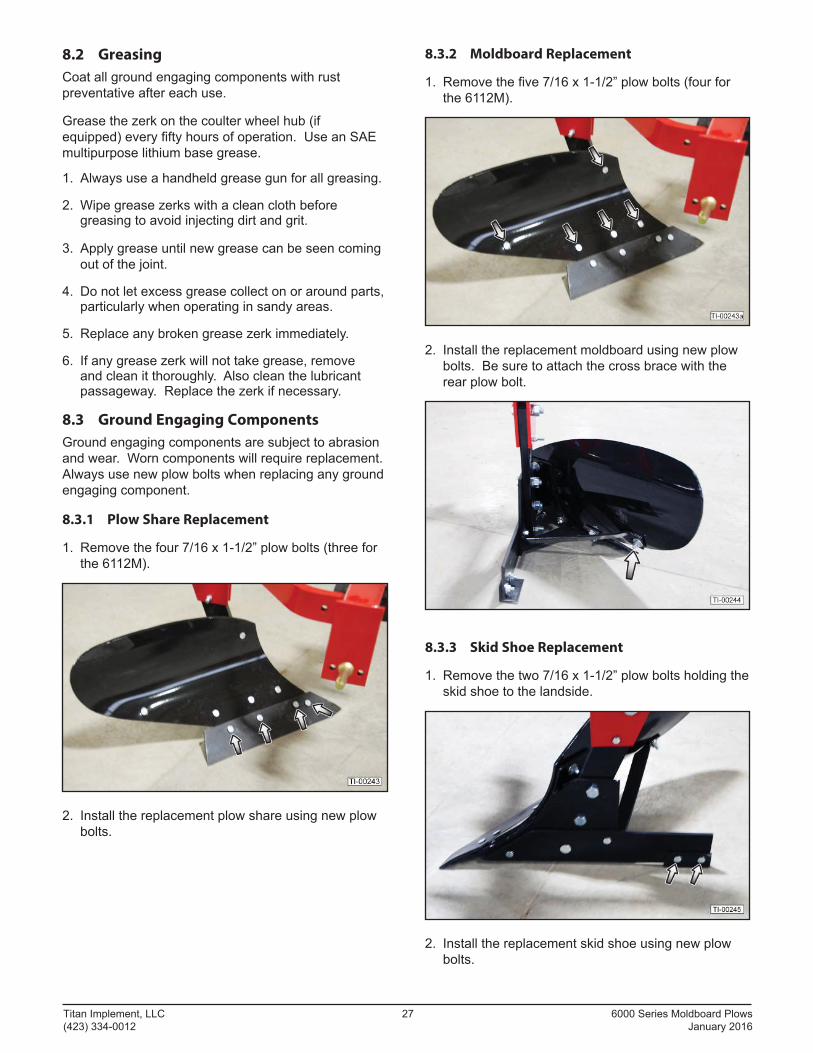
8.3.1 Plow Share Replacement
1. Remove the four 7/16 x 1-1/2” plow bolts (three for the 6112M).
2. Install the replacement plow share using new plow bolts.
8.3.2 Moldboard Replacement
1. Remove the fi ve 7/16 x 1-1/2” plow bolts (four for the 6112M).
2. Install the replacement moldboard using new plow bolts. Be sure to attach the cross brace with the rear plow bolt.
8.3.3 Skid Shoe Replacement
1. Remove the two 7/16 x 1-1/2” plow bolts holding the skid shoe to the landside.
2. Install the replacement skid shoe using new plow bolts.
6000 Series Moldboard Plows 28 Titan Implement, LLC January 2016 (423) 334-0012
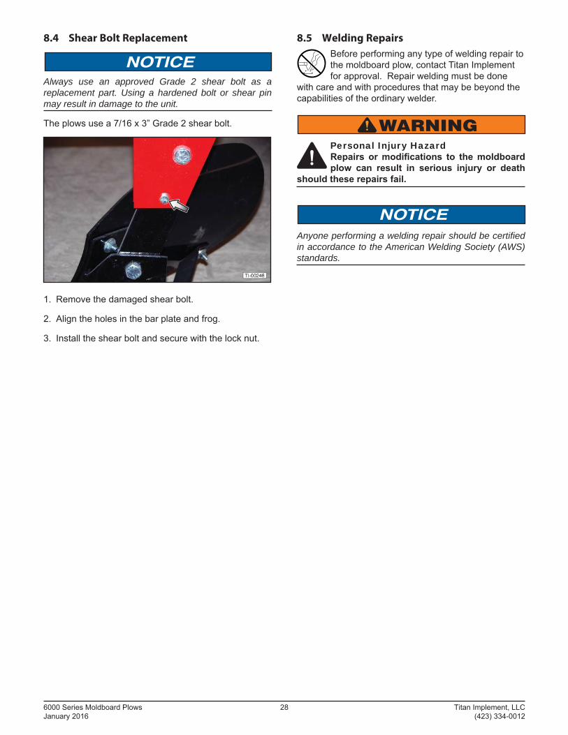
8.4 Shear Bolt Replacement
NOTICEAlways use an approved Grade 2 shear bolt as a replacement part. Using a hardened bolt or shear pin may result in damage to the unit.
The plows use a 7/16 x 3” Grade 2 shear bolt.
1. Remove the damaged shear bolt.
2. Align the holes in the bar plate and frog.
3. Install the shear bolt and secure with the lock nut.
8.5 Welding Repairs
Before performing any type of welding repair to the moldboard plow, contact Titan Implement for approval. Repair welding must be done
with care and with procedures that may be beyond the capabilities of the ordinary welder.
WARNINGPersonal Injury Hazard Repairs or modifi cations to the moldboard plow can result in serious injury or death
should these repairs fail.
NOTICEAnyone performing a welding repair should be certifi ed in accordance to the American Welding Society (AWS) standards.
Titan Implement, LLC 29 6000 Series Moldboard Plows (423) 334-0012 January 2016
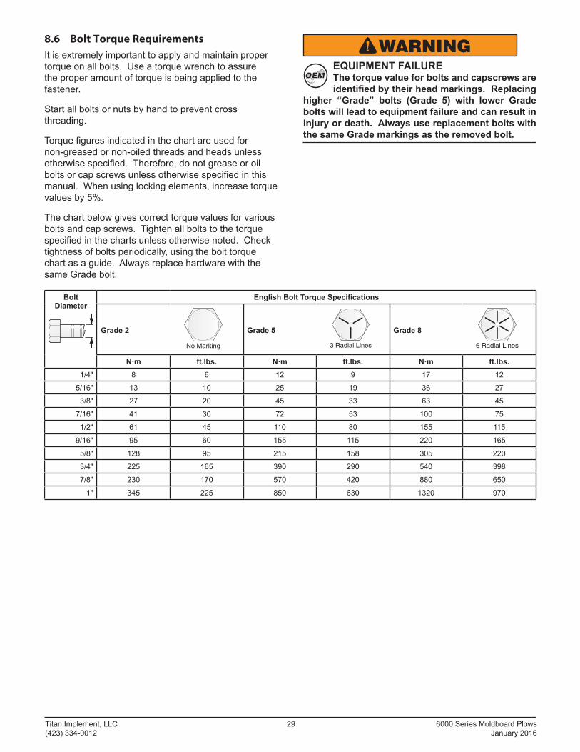
8.6 Bolt Torque Requirements
It is extremely important to apply and maintain proper torque on all bolts. Use a torque wrench to assure the proper amount of torque is being applied to the fastener.
Start all bolts or nuts by hand to prevent cross threading.
Torque fi gures indicated in the chart are used for non-greased or non-oiled threads and heads unless otherwise specifi ed. Therefore, do not grease or oil bolts or cap screws unless otherwise specifi ed in this manual. When using locking elements, increase torque values by 5%.
The chart below gives correct torque values for various bolts and cap screws. Tighten all bolts to the torque specifi ed in the charts unless otherwise noted. Check tightness of bolts periodically, using the bolt torque chart as a guide. Always replace hardware with the same Grade bolt.
BoltDiameter
English Bolt Torque Specifications
Grade 2
No Marking
Grade 5
3 Radial Lines
Grade 8
6 Radial Lines
N·m ft.lbs. N·m ft.lbs. N·m ft.lbs.1/4" 8 6 12 9 17 12
5/16" 13 10 25 19 36 27
3/8" 27 20 45 33 63 45
7/16" 41 30 72 53 100 75
1/2" 61 45 110 80 155 115
9/16" 95 60 155 115 220 165
5/8" 128 95 215 158 305 220
3/4" 225 165 390 290 540 398
7/8" 230 170 570 420 880 650
1" 345 225 850 630 1320 970
WARNINGOEMOEM
EQUIPMENT FAILURE The torque value for bolts and capscrews are identifi ed by their head markings. Replacing
higher “Grade” bolts (Grade 5) with lower Grade bolts will lead to equipment failure and can result in injury or death. Always use replacement bolts with the same Grade markings as the removed bolt.
6000 Series Moldboard Plows 30 Titan Implement, LLC January 2016 (423) 334-0012
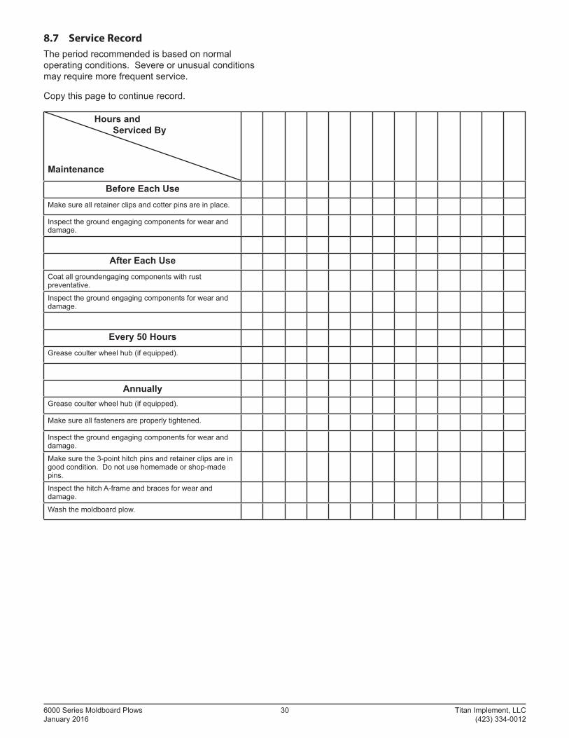
8.7 Service Record
The period recommended is based on normal operating conditions. Severe or unusual conditions may require more frequent service.
Copy this page to continue record.
Hours and Serviced By
Maintenance
Before Each UseMake sure all retainer clips and cotter pins are in place.
Inspect the ground engaging components for wear and damage.
After Each UseCoat all groundengaging components with rust preventative.
Inspect the ground engaging components for wear and damage.
Every 50 HoursGrease coulter wheel hub (if equipped).
AnnuallyGrease coulter wheel hub (if equipped).
Make sure all fasteners are properly tightened.
Inspect the ground engaging components for wear and damage.
Make sure the 3-point hitch pins and retainer clips are in good condition. Do not use homemade or shop-made pins.
Inspect the hitch A-frame and braces for wear and damage.
Wash the moldboard plow.
Titan Implement, LLC 31 6000 Series Moldboard Plows (423) 334-0012 January 2016
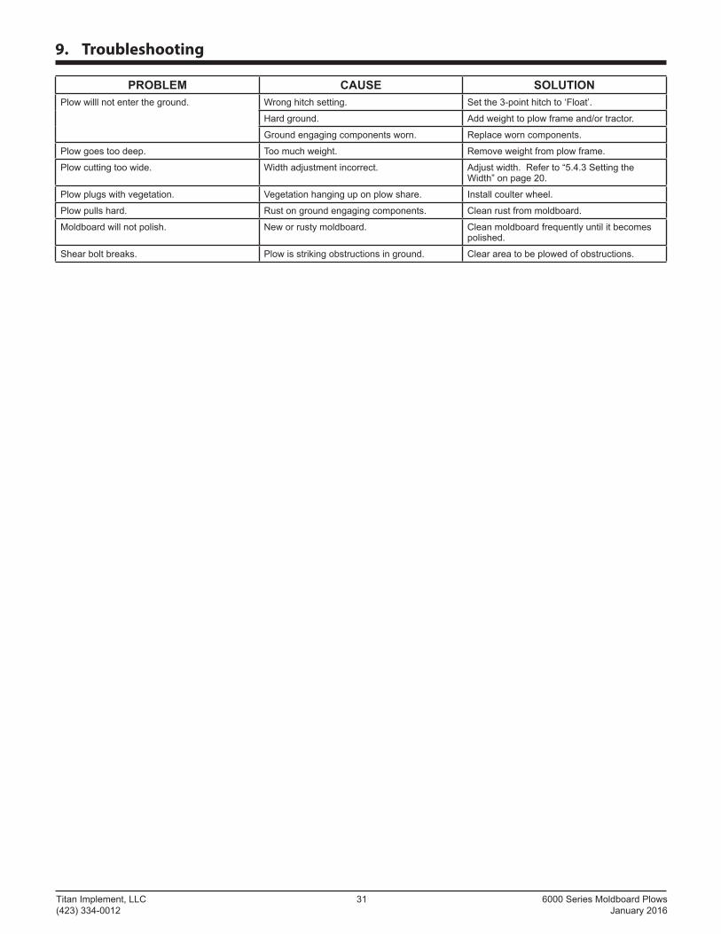
9. Troubleshooting
PROBLEM CAUSE SOLUTIONPlow willl not enter the ground. Wrong hitch setting. Set the 3-point hitch to ‘Float’.
Hard ground. Add weight to plow frame and/or tractor.
Ground engaging components worn. Replace worn components.
Plow goes too deep. Too much weight. Remove weight from plow frame.
Plow cutting too wide. Width adjustment incorrect. Adjust width. Refer to “5.4.3 Setting the Width” on page 20.
Plow plugs with vegetation. Vegetation hanging up on plow share. Install coulter wheel.
Plow pulls hard. Rust on ground engaging components. Clean rust from moldboard.
Moldboard will not polish. New or rusty moldboard. Clean moldboard frequently until it becomes polished.
Shear bolt breaks. Plow is striking obstructions in ground. Clear area to be plowed of obstructions.
6000 Series Moldboard Plows 32 Titan Implement, LLC January 2016 (423) 334-0012
10. Warranty
TITAN IMPLEMENT
LIMITED WARRANTYTITAN IMPLEMENT, LLC. (the “Manufacturer”) warrants, only to the original Purchaser, this equipment will be free from defects in material and workmanship, under normal use and service, for one (1) year from the date of purchase providing this equipment is purchased for individual use only. Commercial use of this equipment is not covered under any warranty. This warranty does not apply to any equipment which has been damaged or which has been subjected to change, misuse, negligence, abnormal wear and tear, alterations, tampering, or failure to follow operating instructions. This warranty does not cover any product or parts not manufactured by Titan Implement, LLC.
Shearbolts must be approved Grade 2 shearbolts.
Under this warranty, the Manufacturer will repair or replace any part which the Manufacturer determines has failed during the period of the warranty due to defects in material or workmanship. After written approval by the manufacturer, the equipment or defective part must be returned to Titan Implement, LLC.
Warranty coverage and performance is expressly conditioned upon the return of the completed registration form to Titan Implement, LLC, PO Box 649, Decatur, Tennessee 37322.
Titan Implement, LLC reserves the right to make improvements and changes in specifi cations without notice or obligation to modify previously sold units. The Owner’s Manual describes the proper assembly procedures for your implement and furnishes operating and maintenance recommendations to help you obtain long and satisfactory service.
PURCHASER’S EXCLUSIVE REMEDY FOR BREACH OF WARRANTY, OTHER DEFECT, OR CONDUCT GIVING RISE TO LIABILITY SHALL BE THE REPAIR OR REPLACEMENT OF THE PRODUCT SOLD, AND THE MANUFACTURER UNDER NO CIRCUMSTANCES SHALL BE LIABLE FOR ECONOMIC LOSS OR INCIDENTAL OR CONSEQUENTIAL DAMAGES. THE MANUFACTURER DISCLAIMS ALL IMPLIED WARRANTIES, INCLUDING THE WARRANTY OF MERCHANTABILITY AND FITNESS FOR PURPOSE.
Purchaser and Titan Implement, LLC hereby (a) submit to the non-exclusive jurisdiction of the courts of competent jurisdiction in Meigs County, Tennessee, and the United State District Court for the Eastern District of Tennessee for resolution of any dispute concerning this Limited Warranty or the rights or obligations of Purchaser and/or Titan Implement, LLC; (b) agree that any litigation commenced in Tennessee in connection with this Limited Warranty shall be venued in either the Meigs County, Tennessee District Court, or the United States District Court, Eastern District of Tennessee, Southern Division, and (c) waive any objection it may have as to any such action or proceeding brought in such court that such court is an inconvenient forum. Nothing herein shall limit the right of Purchaser or Titan Implement, LLC (or the right of any permitted successor or assign of either) to bring proceedings against the other in the courts of any other jurisdiction wherein any assets of such other party may be located.
IMPLEMENT
Titan Implement, LLC 33 6000 Series Moldboard Plows (423) 334-0012 January 2016
WARRANTY REGISTRATION FORMMoldboard Plow
THIS REGISTRATION FORM MUST BE ON FILE WITH TITAN IMPLEMENT, LLC. WITHIN 30 DAYS OF DELIVERY TO PURCHASER, OR WARRANTY CLAIM WILL NOT BE HONORED.
PLEASE RETURN COMPLETED FORM BY E-MAIL, FAX, OR MAIL:
E-MAIL: [email protected]
FAX: (423) 334-0023
MAIL: PO BOX 649, DECATUR, TN 37322
MODEL: __________________ SERIAL #: ___________________ DELIVERY DATE: ______________
TRACTOR MAKE & MODEL BEING USED WITH ABOVE UNIT: ________________________________
PURCHASER’S NAME: ________________________________________________________________
ADDRESS: __________________________________________________________________________
CITY: _________________________________ STATE: __________________ ZIP: _______________
SELLING DEALER’S NAME: ____________________________________________________________
CITY: _________________________________ STATE: __________________ ZIP: _______________
I have read all warranties and agree with these conditions. I agree to read and follow all safetyinstructions outlined in this manual before operating this moldboard plow.
Purchaser’s signature: _________________________________________________________________
IMPLEMENT
Cut
Her
e to
Rem
ove
Page
or M
ake
Cop
ies
of T
his
Page

6000 Series Moldboard Plows 34 Titan Implement, LLC January 2016 (423) 334-0012
Titan Implement, LLC 35 6000 Series Moldboard Plows (423) 334-0012 January 2016
11. Parts
Replacement parts are available from your authorized Dealer Parts Department or from Titan Implement.
The following pages contain a list of serviceable parts for the Titan Implement moldboard plow.
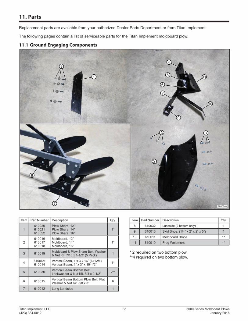
11.1 Ground Engaging Components
Item Part Number Description Qty.
1610020610021610022
Plow Share, 12”Plow Share, 14”Plow Share, 16”
1*
2610016610017610018
Moldboard, 12”Moldboard, 14”Moldboard, 16”
1*
3 610019 Moldboard & Plow Share Bolt, Washer & Nut Kit, 7/16 x 1-1/2” (5 Pack) 1
4 61006M610014
Vertical Beam, 1 x 3 x 16” (6112M)Vertical Beam, 1” x 3” x 19-1/2” 1*
5 610030 Vertical Beam Bottom Bolt, Lockwasher & Nut Kit, 3/4 x 2-1/2” 2**
6 610015 Vertical Beam Bottom Plow Bolt, Flat Washer & Nut Kit, 5/8 x 3” 6
7 610012 Long Landside 1
Item Part Number Description Qty.
8 610032 Landside (2 bottom only) 1
9 610013 Skid Shoe, (1/4” x 2” x 2” x 5”) 1
10 610011 Moldboard Brace 1*
11 610010 Frog Weldment 1*
* 2 required on two bottom plow.**4 required on two bottom plow.
6000 Series Moldboard Plows 36 Titan Implement, LLC January 2016 (423) 334-0012
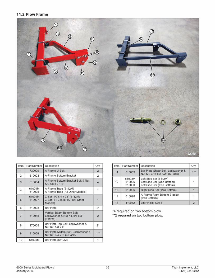
11.2 Plow Frame
Item Part Number Description Qty.
1 730009 A-Frame U-Bolt 2
2 610003 A-Frame Bottom Bracket 2
3 610004 A-Frame Bottom Bracket Bolt & Nut Kit, 5/8 x 2-1/2” 4
4 61001M610005
A-Frame Tube (6112M)A-Frame Tube (All Other Models) 1
561004M610007
Z-Bar, 1/2 x 4 x 28” (6112M)Z-Bar, 1 x 3 x 28-1/2” (All Other Models)
1
6 610008 Bar Plate 2*
7 610015Vertical Beam Bottom Bolt, Lockwasher & Nut Kit, 5/8 x 3” (6112M)
2
8 170008 Bar Plate Top Bolt, Lockwasher & Nut Kit, 5/8 x 4” 2*
9 110068 Bar Plate Middle Bolt, Lockwasher & Nut Kit, 3/4 x 3” (4 Pack) 1**
10 61005M Bar Plate (6112M) 1
Item Part Number Description Qty.
11 610009 Bar Plate Shear Bolt, Lockwasher & Nut Kit, 7/16 x 2-1/2” (5 Pack) 1**
1261003M610006610090
Left Side Bar (6112M)Left Side Bar (One Bottom)Left Side Bar (Two Bottom)
1
13 610006 Right Side Bar (Two Bottom) 1
14 610028 A-Frame Right Bottom Bracket (Two Bottom) 1
15 110032 Lift Pin Kit, CAT l 2
*4 required on two bottom plow.**2 required on two bottom plow.
Titan Implement, LLC 37 6000 Series Moldboard Plows (423) 334-0012 January 2016
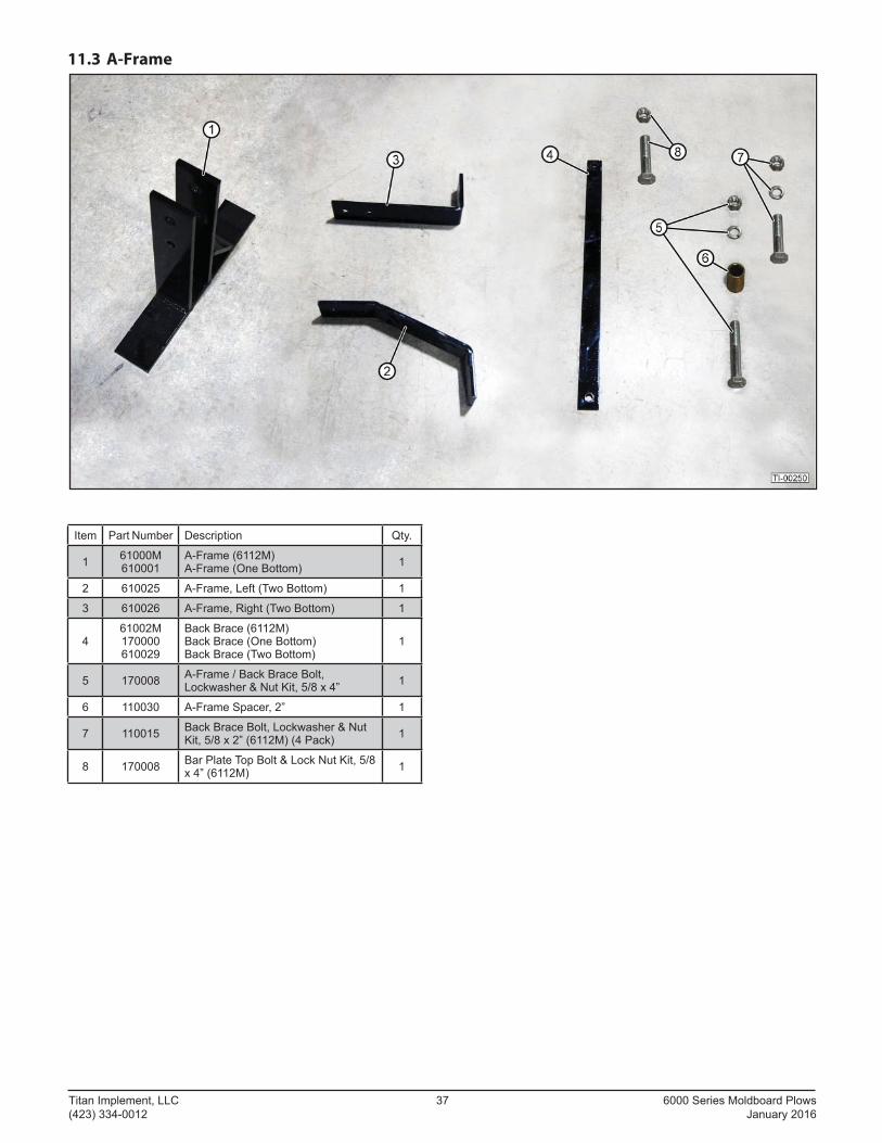
11.3 A-Frame
Item Part Number Description Qty.
1 61000M610001
A-Frame (6112M)A-Frame (One Bottom) 1
2 610025 A-Frame, Left (Two Bottom) 1
3 610026 A-Frame, Right (Two Bottom) 1
461002M170000610029
Back Brace (6112M)Back Brace (One Bottom)Back Brace (Two Bottom)
1
5 170008 A-Frame / Back Brace Bolt, Lockwasher & Nut Kit, 5/8 x 4” 1
6 110030 A-Frame Spacer, 2” 1
7 110015 Back Brace Bolt, Lockwasher & Nut Kit, 5/8 x 2” (6112M) (4 Pack) 1
8 170008 Bar Plate Top Bolt & Lock Nut Kit, 5/8 x 4” (6112M) 1
6000 Series Moldboard Plows 38 Titan Implement, LLC January 2016 (423) 334-0012
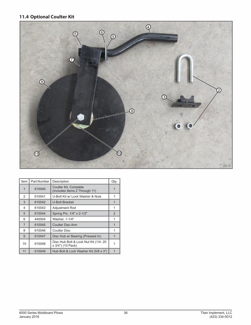
11.4 Optional Coulter Kit
Item Part Number Description Qty.
1 610040 Coulter Kit, Complete(Includes Items 2 Through 11) 1
2 610041 U-Bolt Kit w/ Lock Washer & Nuts 1
3 610042 U-Bolt Bracket 1
4 610043 Adjustment Rod 1
5 610044 Spring Pin, 1/4" x 2-1/2" 2
6 440004 Washer, 1-1/4" 1
7 610045 Coulter Disc Arm 1
8 610046 Coulter Disc 1
9 610047 Disc Hub w/ Bearing (Pressed In) 1
10 610048 Disc Hub Bolt & Lock Nut Kit (1/4- 20 x 3/4") (10 Pack) 1
11 610049 Hub Bolt & Lock Washer Kit (5/8 x 3") 1
Titan Implement, LLC 39 6000 Series Moldboard Plows (423) 334-0012 January 2016
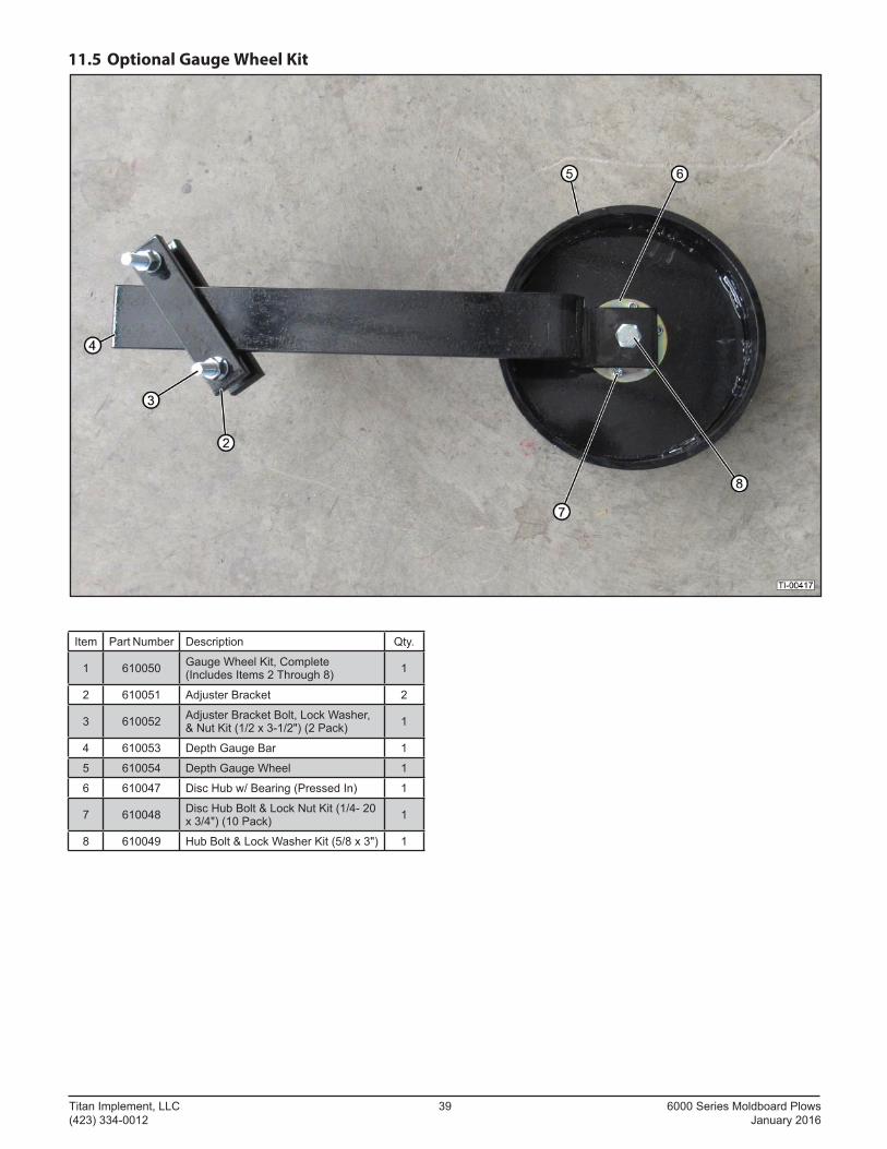
11.5 Optional Gauge Wheel Kit
Item Part Number Description Qty.
1 610050 Gauge Wheel Kit, Complete(Includes Items 2 Through 8) 1
2 610051 Adjuster Bracket 2
3 610052 Adjuster Bracket Bolt, Lock Washer, & Nut Kit (1/2 x 3-1/2") (2 Pack) 1
4 610053 Depth Gauge Bar 1
5 610054 Depth Gauge Wheel 1
6 610047 Disc Hub w/ Bearing (Pressed In) 1
7 610048 Disc Hub Bolt & Lock Nut Kit (1/4- 20 x 3/4") (10 Pack) 1
8 610049 Hub Bolt & Lock Washer Kit (5/8 x 3") 1

6000 Series Moldboard Plows 40 Titan Implement, LLC January 2016 (423) 334-0012
Notes
Titan Implement, LLC 41 6000 Series Moldboard Plows (423) 334-0012 January 2016
Notes
6000 Series Moldboard Plows 42 Titan Implement, LLC January 2016 (423) 334-0012
Notes


Form No. 6100MPrinted in USA 09-2016