Embed Size (px)
Citation preview

Solutions by the people of Zimmer Spine.zimmerspine.com
TiTLE® 2Polyaxial Spinal System
Surgical Technique
Total Page Count is 36

Versatile solutions From the people of Zimmer Spine.
At Zimmer Spine we appreciate the fact that no two surgeons are alike. Which is why
we create versatile spinal solutions that embrace a range of surgeon preferences.
We want you to feel comfortable and confident in your surgical procedures with
solutions such as the TiTLE 2 Polyaxial Spinal System. It features simple, intuitive
instrumentation and facilitates either an open or an MIS approach. All so you can
deliver real patient results on your terms. It’s another solution that supports you in
your quest to provide the absolute best in spinal care, brought to you by the people
of Zimmer Spine.
Total Page Count is 36

Indications/Contraindications 1
TiTLE 2 Implants 3
TiTLE 2 Instruments 5
Surgical Technique 11
Kit Contents 27
Warnings and Precautions 31
Table of Contents
Total Page Count is 36

1
Indications/Contraindications
Indications
The TiTLE 2 Polyaxial Spinal System is indicated for degenerative disc disease (defined as discogenic
back pain with degeneration of the disc confirmed by history and radiographic studies). Levels of
fixation are for the Thoracic, Lumbar and Sacral spine.
The TiTLE 2 Polyaxial Spinal System is a Pedicle Screw System intended to provide immobilization
and stabilization of spinal segments in skeletally mature patients as an adjunct to fusion in the
treatment of the following acute and chronic instabilities or deformities of the thoracic, lumbar, and
sacral spine: degenerative spondylolisthesis with objective evidence of neurologic impairment,
fracture, dislocation, scoliosis, kyphosis, spinal tumor, and failed previous fusion (pseudoarthrosis).
The TiTLE 2 Polyaxial Spinal System is also indicated for pedicle screw fixation for severe
spondylolisthesis (grades 3 and 4) at L5-S1, in skeletally mature patients, when autogenous bone
graft is used, when affixed to the posterior lumbosacral spine, and intended to be removed after
solid fusion is attained. Levels of fixation are from L3-S1.
In addition, TiTLE 2 Polyaxial Spinal System, when not used with pedicle screws, is indicated
for hook, wire, and/or sacral screw fixation from T1 to the ilium sacrum. The non-pedicle screw
indications are spondylolisthesis, degenerative disc disease, (defined as discogenic back pain with
degeneration of the disc confirmed by history and radiographic studies), deformities (scoliosis,
lordosis, and kyphosis), tumor, fracture, and previous failed fusion surgery.
The TiTLE 2 Poly Axial Spinal System can also be linked to the Minit® Posterior Cervical and Upper
Thoracic Fixation System.
Total Page Count is 36
2
Contraindications
Contraindications include but are not limited to:
• History of recent infection, systemic, spinal, or localized
• Morbid obesity
• Mental illness
• Alcoholism or drug abuse
• Fever or Leukocytes
• Pregnancy
• Metal sensitivity / allergies to implant materials
• Severe Osteopenia
• Presence of congenital abnormalities, vague spinal anatomy, tumors, or any other condition
which may prevent secure implant screw fixation and/or decrease the useful life of the device
• Any condition where the device will interfere with anatomical structures or physiological
performance, including inadequate tissue coverage over the operational site
• For pedicle screw cases, missing or congenitally deformed pedicles of the fifth lumbar vertebrae
• Patients unwilling or unable to follow post-operative care instructions
• Any circumstances not described under the heading, INDICATIONS
Total Page Count is 36

3
TiTLE 2 Implants
T-Link, GoldenGate® Cross Connector (30 - 80mm) 161-3030 to 161-3080
Curved Rod (5.5mm x 20mm - 5.5mm x 80mm) 535-5020 to 535-5080
Straight Rod (5.5mm x 40mm - 5.5mm x 200mm) 500-5040 to 500-5200
Hex-End Straight Rod (5.5mm x 250mm - 5.5mm x 450mm) 500-5250 to 500-5450
Note: Rod-to-rod connectors have not been validated for use through the FlexPosure portal.
GoldenGate Cross Connectors are not designed to be used through the FlexPosure portal.
TiTLE 2 Axial Rod-to-Rod Connector (5.5mm to 5.5mm) 502-5555
Minit Axial Rod-to-Rod Connector (3.25mm to 5.5mm) 502-3255
Cap Screw 800-0000
Total Page Count is 36

4
* TiTLE 2 Cannulated Pedicle Screw 5.5, 6.5, 7.5mm 810-5535 to 810-7535
TiTLE 2 Offset Rod-to-Rod Connector (5.5mm - 5.5mm) 501-5555
Minit Offset Rod-to-Rod Connector (3.25mm - 5.5mm) 501-3255
Pedicle Screw (5.5mm x 30mm - 7.5mm x 55mm) 800-5530 to 800-7555
Polyaxial Screw (4.5mm x 25mm - 4.5mm x 45mm) 800-4525 to 800-4545
Part # Diameter Color length inCrement tray
4.5mm Magenta 25 - 45mm 5mm 4.5mm Implant Kit
5.5mm Green 30 - 55mm 5mm Standard Kit
6.5mm Yellow 30 - 55mm 5mm Standard Kit
7.5mm Blue 30 - 55mm 5mm Standard Kit
800-5560
to
800-7570
Part # Diameter Color length inCrement tray
5.5mm Green 60 - 70mm 5mm Long Length Screw Kit
6.5mm Yellow 60 - 70mm 5mm Long Length Screw Kit
7.5mm Blue 60 - 70mm 5mm Long Length Screw Kit
800-5530
to
800-7555
TiTLE 2 Pedicle Screws
*Refer to surgical technique L1519 for use with guidewire.
Total Page Count is 36

5
TiTLE 2 Instruments
Awl ET1006-01
Marks the pedicle entry point.
Straight Pedicle Probe ET1004-01
Creates a path through the pedicle and into the vertebral body.
Endo Pedicle Marker Driver ET1076-01
Drives pedicle markers.
Endo Pedicle Marker Right ET1075-01
Placed in the pedicle canal to identify appropriate screwtrajectory fluoroscopically. Single-band design indicatesplacement on the right pedicle.
Endo Pedicle Marker Left ET1074-01
Placed in the pedicle canal to identify appropriate screw trajectory fluoroscopically. Double-band design indicates placement on the left pedicle.
Curved Pedicle Probe ET1005-01
Creates a path through the pedicle and into the vertebral body.
Total Page Count is 36

6
Sounding Probe Straight ET1002-01
Sounding Probe Curved ET1003-01
Checks pedicle integrity prior to tapping andscrew insertion.
Solid Awl-in-One (4.5mm - 7.5mm) ET1120-45 to ET1120-75
Provides awl and tap in a single tool. An alternative to the standard Bone Awl.
Solid Tap (4.5 - 7.5mm) ET1088-45 to ET1088-75
* Cannulated Tap (5.5 - 7.5mm) ET1090-55 to ET1090-75
Taps pedicle to prepare for polyaxial screw placement.
Solid Sharp Tap (4.5 - 7.5mm) ET1121-45 to ET1121-75
* Cannulated Sharp Tap (5.5 - 7.5mm) ET1121-55C to ET1121-75C
Taps pedicle to prepare for polyaxial screw placement; sharper tip alternative.
Locking Screwdriver, Solid, 3.5mm ET1091-01
Drives and adjusts polyaxial pedicle screws; includes locking threads to provide tight connection between driver and screw. Can be used with Locking Screwdriver Sleeve.
*Refer to surgical technique L1519 for use with guidewire.
Total Page Count is 36

7
Captive Hex Screwdriver (3.5mm, 4.0mm) ET1051-01 (3.5mm), ET1052-01 (4.0mm)
Drives and adjusts polyaxial pedicle screws.
Head Positioner ET1134-01
Aligns polyaxial screw heads for rod placement.
Endoscopic Rod Holder ET1062-01
Holds rod for placement in the TiTLE 2 construct; allows rod to be held in both horizontal and vertical orientation.
Rod Holder ET1011-01
Holds rod for placement in the TiTLE 2 construct.
French Bender ET1036-01
Contour rods as necessary to conform to the construct.
Cap Screw Extractor Tip ET1081-01, ET1082-01
Note: Single use disposable instrument
Total Page Count is 36

8
Cap Screw Extractor Ext ET1080-01
Provides option for removal of cap screws. Used with Cap Screw Extractor Tip.
Rod Rotation Wrench ET1025-01
Provides de-rotation and anatomical correction to rods.
In Situ Bender (Right, Left) ET1113-01, ET1113-02
Provide sagittal plane adjustment and may be used incombination.
4.0mm Ball Tip Screwdriver ET1119-01
Provides option to place cap screw when delivering from angle that is not collinear with polyaxial screw.
Note: Not to be used for Final Tightening.
Compressor ET1008-01
Compresses implants axially along the rod.
Distractor ET1009-01
Distracts implants axially along the rod.
Two-Piece Distractor ET1131-01
Provides alternative option for axial distraction along the rod. Used with Compressor / Distractor Screwdriver.
Two-Piece Compressor ET1130-01
Provides alternative option for axial compression along the rod. Used with Compressor / Distractor Screwdriver.
Total Page Count is 36

9
Counter Torque ET1132-01
Serves as counter torque wrench.
Marksman® Counter Torque Guide ET1054-01
Eases initiation of closure tops into screws and functions as a traditional counter torque wrench.
MIS Compressor/Distractor ET1096-01
Provides axial compression and/or distraction along the rod.
Compressor/Distractor Screwdriver ET1133-01
Used with 2- Piece Compressor and 2- Piece Distractor.
Note: For use with longer counter torque.
Rod Manipulator ET1117-01
Achieve spondylolisthesis reduction and rod approximation.
Reducer ET1095-01
Used with Reducer Driver as an alternative for spondylolisthesis reduction and rod approximation.
Total Page Count is 36

10
Reducer Driver ET1094-01
Used with Reducer as an alternative for spondylolisthesis reduction and rod approximation.
Bone Screw Remover ET1093-01
Alternative to remove pedicle screws.
Straight Ratcheting Handle ET1001-01
Attaches to Screw Driver for initial screw placement. Also utilized for the removal or revision of system constructs.
T-Ratcheting Handle ET1049-01
Attaches to Screw Driver for initial screw placement. Also utilized for the removal or revision of system constructs.
Torque Limiting T-Handle (90 in.-lbs.) ET1098-01
Optimally locks and limits input torque to 90 in-lbs. Used with 4.0mm Driver to lock cap screw.
Torque Limiting Handle (50 in-lbs) ET1020-01
Optimally locks and limits input torque to 50 in-lbs. Used with the 3.5mm Captive Hex driver to lock GoldenGate Transverse Connectors.
Total Page Count is 36
11
Surgical Technique
Pedicle Preparation
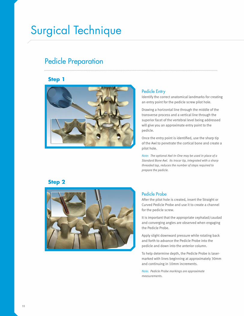
Pedicle EntryIdentify the correct anatomical landmarks for creating
an entry point for the pedicle screw pilot hole.
Drawing a horizontal line through the middle of the
transverse process and a vertical line through the
superior facet of the vertebral level being addressed
will give you an approximate entry point to the
pedicle.
Once the entry point is identified, use the sharp tip
of the Awl to penetrate the cortical bone and create a
pilot hole.
Note: The optional Awl-In-One may be used in place of a
Standard Bone Awl. Its trocar tip, integrated with a sharp
threaded tap, reduces the number of steps required to
prepare the pedicle.
Step 1
Pedicle Probe After the pilot hole is created, insert the Straight or
Curved Pedicle Probe and use it to create a channel
for the pedicle screw.
It is important that the appropriate cephalad/caudad
and converging angles are observed when engaging
the Pedicle Probe.
Apply slight downward pressure while rotating back
and forth to advance the Pedicle Probe into the
pedicle and down into the anterior column.
To help determine depth, the Pedicle Probe is laser-
marked with lines beginning at approximately 30mm
and continuing in 10mm increments.
Note: Pedicle Probe markings are approximate
measurements.
Step 2
Total Page Count is 36

12
Tapping (if necessary) TiTLE 2 screws are fully threaded and have a self-
tapping feature designed to eliminate the need to tap
the pedicle canal.
In many situations where patient bone quality is
compromised or where there is a dense cortical layer, it
may be necessary to utilize one of the size-specific taps
in the TiTLE 2 system.
If necessary, choose the appropriate diameter tap
based on the diameter of the screw to be implanted.
Attach the tap to either the Straight Ratcheting or
T-Ratcheting Handle. Shift the handle into the forward
position and advance clockwise into the pedicle canal.
Laser-marked lines on the tap begin at 30mm and
continue in increments of 10mm.
Advance to the desired depth, shift the ratcheting
handle in reverse and remove the tap in a counter-
clockwise direction.
Step 4
Pedicle Verification Use the Straight or Curved Sounding Probe to palpate
the channel, verifying the integrity of the pedicle wall
and confirming that the anterior cortex of the vertebral
body has not been penetrated.
Step 3
Total Page Count is 36

13
Screw Placement
The TiTLE 2 system offers two options for implanting pedicle screws.
Assemble 3.5mm Captive Hex ScrewdriverChoose the appropriate diameter and length of the
TiTLE 2 polyaxial pedicle screw.
Attach either the Straight or T-Ratcheting Handle to the
3.5mm Captive Hex Screwdriver. Insert the hex end
of the driver into the hex feature on the center of the
screw shank.
Step 5 Option 1
Assemble 3.5mm Locking ScrewdriverChoose the appropriate diameter and length of the
TiTLE 2 polyaxial pedicle screw.
Attach either the Straight or T-Ratcheting Handle to the
3.5mm Locking Screwdriver. Insert the hex end of the
driver into the hex feature on the center of the screw
shank.
Confirm that the shank of the screw is straight, and
advance the sleeve into the threads in the polybody
until tight.
Step 5 Option 2
Total Page Count is 36
14
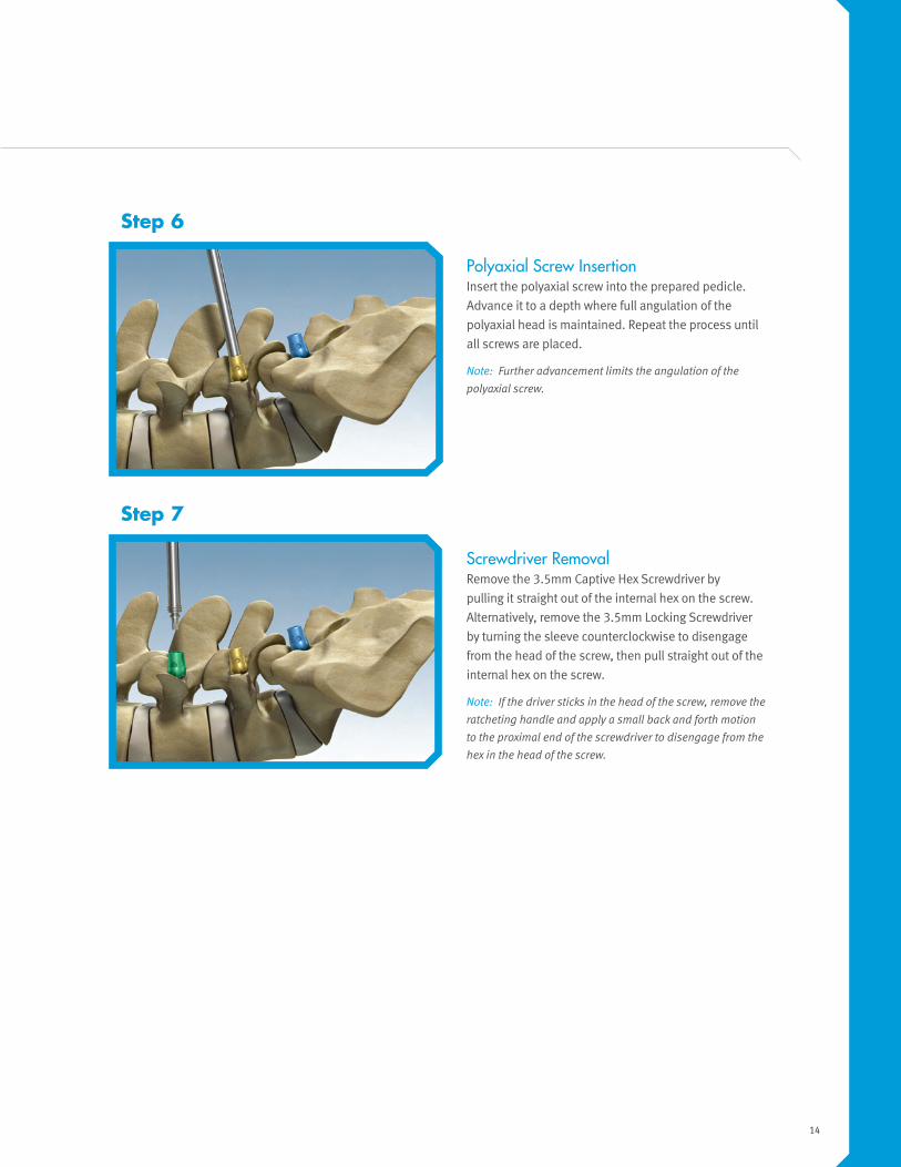
Screwdriver Removal Remove the 3.5mm Captive Hex Screwdriver by
pulling it straight out of the internal hex on the screw.
Alternatively, remove the 3.5mm Locking Screwdriver
by turning the sleeve counterclockwise to disengage
from the head of the screw, then pull straight out of the
internal hex on the screw.
Note: If the driver sticks in the head of the screw, remove the
ratcheting handle and apply a small back and forth motion
to the proximal end of the screwdriver to disengage from the
hex in the head of the screw.
Step 7
Polyaxial Screw Insertion Insert the polyaxial screw into the prepared pedicle.
Advance it to a depth where full angulation of the
polyaxial head is maintained. Repeat the process until
all screws are placed.
Note: Further advancement limits the angulation of the
polyaxial screw.
Step 6
Total Page Count is 36

15
Head PositioningUse the Head Positioner instrument to align all the
polyaxial screw heads.
The friction head feature on the TiTLE 2 polyaxial
screws will ensure their position is maintained once
aligned.
Step 8
Rod Selection Select the desired rod. The TiTLE 2 system offers a
wide range of pre-cut and pre-contoured 5.5mm rods.
Use the Rod Template to assist in determining the
length of the rod and the appropriate amount of
contouring required to achieve the desired sagittal
profile. It is recommended that 3–5mm of the rod
extend beyond the head of the screw on the superior
and inferior ends of the construct.
Table Top Rod Cutters may be used in situations
where one of the pre-cut rod lengths is not ideal.
Rod bending may be necessary to ensure that the rod
is fully seated within the head of the screw. The radius
of the bend can be varied by pulling out and rotating
the central button of the French Rod Bender.
Set the radius to the desired point, insert the rod into
the French Rod Bender and close the handles to apply
the bending force to rod.
Step 9
Screw Placement
Total Page Count is 36

16
Provisional Tightening Attach a cap screw to the 4.0mm Captive Hex Driver.
Insert all cap screws so they are provisionally tight.
Note: The 4.0mm Ball Tip Hex Driver can be used to help
engage the cap screw when a direct angle to the cap screw
cannot be achieved.
Step 11
Rod Placement through Standard Incision Use the Rod Holder to insert the rod into the heads of
the polyaxial screws.
Step 10
Total Page Count is 36

17
Reduction Option
There are four instrument options in the TiTLE 2 system designed to assist with engaging the set screw when the
position of the rod is proud of the polyaxial screw.
Head Positioner (if necessary)The Head Positioner can also be utilized as a rod
pusher. To push the rod, place the rod cutout on the
rod and apply controlled downward pressure until the
rod seats within the head of the polyaxial screw.
Once the rod is within the head of the polyaxial screw,
use the 4.0mm Captive Hex Driver to place the cap
screw.
Step 12 Option 1
Marksman Counter Torque Guide (if necessary)The Marksman Counter Torque Guide can be used to
drive the rod into the head of the screw.
Once the rod is within the head of the polyaxial screw,
use the 4.0mm Captive Hex Driver to place the cap
screw.
Note: The Marksman Counter Torque Guide can also be used
as an alignment guide for starting cap screws.
Step 12 Option 2
Total Page Count is 36

18
Rod Manipulator (if necessary)If the rod requires additional manipulation, the Rod
Manipulator can be used. The Rod Manipulator
attaches to the sides of the screw interfacing with the
round recesses in the sides of the polyaxial screw
head.
Clamp the Rod Manipulator down onto the sides of the
screw and position the instrument so that the forceps’
handle is at a 45° angle relative to the rod.
Turn the adjustment knob on the Rod Manipulator
clockwise until the rod is fully seated within the screw
housing. Use the 4.0mm Captive Hex Driver to place
the cap screw.
Step 12 Option 3
Spondy Reduction Instrument Assembly (if necessary)To assemble, pass the Reduction Driver through the
cannulation in the Reduction Instrument. Thread the
driver until the hex end is extended past the distal end
of the Reduction Instrument.
Attach the cap screw. Once the cap screw is on the
Reduction Driver, turn the driver counterclockwise to
back it up until the cap screw is at the proximal end of
the opening.
Step 12 Option 4a
Total Page Count is 36

19
Spondy Reduction Instrument (if necessary)Attach the Spondy Reduction Instrument to the head of
the polyaxial screw to be reduced.
Advance the Spondy Driver in a clockwise motion; this
will drive the rod into the head of the polyaxial screw.
As the rod is forced into the head of the polyaxial
screw, the cap screw will engage the threads on the
head of the polyaxial screw.
When the cap screw is provisionally tight, release the
Reduction Instrument from the head of the screw and
turn it counterclockwise to disengage from the sides
of the screw.
Once disengaged from the screw, remove by pulling
straight up on the Reduction Instrument and driver.
Standard final tightening technique should be followed.
Step 12 Option 4b
Compression Option
The TiTLE 2 system offers two options for compression in an open surgery.
Standard Open Compression (if necessary)Fully tighten the cap screw on one side of the segment
being translated, while leaving the cap screw loose on
the adjacent screw(s). Perform compression against
the fully tightened screw.
After achieving desired amount of compression, tighten
cap screw. Final cap screw tightening steps should be
followed to fully lock construct.
Step 13 Option 1
Total Page Count is 36

20
Lever-Style Open Compression (if necessary)Four instruments are required for this assembly:
Counter Torque, 4.0mm Driver, Compressor, 90 in-lb
Torque-Limiting Handle.
Place counter torque instrument through Level
Compressor. Place the Counter Torque over the screw
to be compressed with the 4.0mm Driver and 90 in-lb
Torque- Limiting Handle (black) assembly engaged
in the cap screw. Place the Compressor around the
adjacent screw to (off of which to compress).
Squeeze the Counter Torque and Compressor together
to compress the segment. Once desired compression is
achieved, tighten cap screw on compressed screw.
Step 13 Option 2
Standard Open Distraction (if necessary)Fully tighten the cap screw on one side of the segment
being translated, while leaving the set screw loose on
the adjacent screw(s). Perform distraction against the
fully tightened screw.
After achieving the desired amount of distraction,
tighten the cap screw. Final cap screw tightening steps
should be followed to fully lock the construct.
Step 14 Option 1
Distraction Option
The TiTLE 2 system offers two options for distraction in an open surgery.
Total Page Count is 36

21
Lever-Style Open Distraction (if necessary)Four instruments are required for this assembly:
Counter Torque, 4.0mm Driver, Distractor, 90 in-lb
Torque-Limiting Handle.
Place the Counter Torque over the screw to be distracted
with the driver and 90 in-lb Torque-Limiting Handle
(black) assembly engaged in the cap screw. Place the
Distractor against the screw to distract from. Squeeze
Counter Torque and Distractor together to distract the
segment. Once desired distraction is achieved, tighten
the cap screw on the distracted screw.
Step 14 Option 2
Final Tightening
Final Tightening Once all correction procedures have been completed,
the construct is ready for final tightening. Final
tightening requires the Marksman Counter Torque,
4.0mm Captive Hex Screwdriver and 90 in-lb Torque-
Limiting Handle (black).
Attach the Torque-Limiting Handle to the 4.0mm
Captive Hex Screwdriver. Pass the driver assembly
through the cannulated Marksman Counter Torque.
Visually confirm that the hex on the driver fully engages
the hex on the cap screw prior to positioning the
Marksman Counter Torque over the screw head.
Step 15a
Total Page Count is 36

22
Final Tightening While providing the appropriate Counter Torque,
turn the Torque-Limiting Handle (black) clockwise to
advance the cap screw.
The Torque-Limiting Handle will break over / click at 90
in-lbs. Repeat process until all remaining screws are
fully tightened.
Step 15b
Rod-to-Rod Connectors Option
Option 1: 5.5 to 5.5mm Connectors (if necessary)
The set screws for the 5.5mm to 5.5mm connectors have a torque requirement of 50 in-lbs. When final tightening the set
screws, utilize the TiTLE 2 Torque-Limiting Handle (gray) and the TiTLE 2 3.5mm Hex Driver. Both of these items are found
in the TiTLE 2 Spinal Instrumentation System. This is the same gray handle that is used to fully tighten the transverse
connectors and the same 3.5mm Hex Driver used to implant TiTLE 2 pedicle screws.
Option 2: 5.5mm to 3.25mm Connectors (if necessary)The set screws for the 5.5mm to 3.25mm connectors have torque recommendations of 30 in-lbs. When final tightening
the set screws utilize the Minit Torque-Limiting Handle and the TiTLE 2 3.5 mm Captive Hex Driver.
Note: Rod to rod connectors have not been validated for use through the FlexPosure portal.
Total Page Count is 36

23
Transverse Connector Preparation (if necessary)Attach the 50 in-lb Torque-Limiting Handle (gray) to the
3.5mm Captive Hex Screwdriver.
Confirm that all set screws on the Transverse Connector
are loose and will allow for free movement.
Transverse Connectors Option
Transverse Connector Selection (if necessary)Transverse Connectors are used to connect parallel
rod segments. Use the Transverse Connector Template
to determine the appropriate length Transverse
Connector.
Total Page Count is 36

24
Transverse Connector Placement (if necessary)Using the Rod Holder, position the selected Transverse
Connector over the rods.
Tighten the outer set screws on the Transverse
Connector first. Turn the driver assembly clockwise until
the 50 in-lb Torque-Limiting Handle breaks over / clicks.
Tighten center set screw. Turn the driver assembly
clockwise until the 50 in-lb Torque-Limiting Handle
breaks over / clicks.
Construct Removal Option
Removal and Revision (if necessary)The TiTLE 2 system provides instrumentation
specifically designed for removal. If the center hex
in screw head can be accessed, utilize either the
3.5mm Captive Hex Screwdriver or the 3.5mm Locking
Screwdriver to remove the screw. If the center hex
feature on the screw cannot be accessed, the Bone
Screw Remover should be used.
Remove all cap screws from the screw. Remove the rod
from the screw heads.
Attach Ratcheting Handle to Bone Screw Remover.
Turn the Racheting Handle counterclockwise to
remove the screw.
Total Page Count is 36

25
TiTLE 2 Kit Contents
Part Number Description Standard Kit Quantity
ET1008-01 Compressor 1
ET1009-01 Distractor 1
ET1010-01 Rod Template 1
ET1011-01 Rod Holder 1
ET1025-01 Rod Rotation Wrench 1
ET1036-01 French Bender 1
ET1043-01 T-Link Template, Packaging 1
ET1049-01 Ratcheting T-Handle, Grey 1
ET1052-01 Captive Hex Screwdriver, 4.0mm 2
ET1054-01 Marksman Countertorque Guide 1
ET1062-01 Endscopic Rod Holder 1
ET1093-01 TiTLE 2 Bone Screw Remover 1
ET1094-01 TiTLE 2 Reducer Driver 1
ET1095-01 TiTLE 2 Reducer 1
ET1096-01 MIS Compressor/Distractor 1
ET1097-01 MIS Compressor/Distractor Driver 1
ET1020-01 Torque Limiting Handle 1
ET1098-01 Torque Limiting T-Handle 1
TiTLE 2 Instruments
Module Number ET4000-42
Total Page Count is 36

26
Part Number Description Standard Kit Quantity
ET1001-01 Ratchet Handle 2
ET1002-01 Sounding Probe Straight 1
ET1003-01 Sounding Probe Canned 1
ET1004-01 Straight Pedicle Probe 1
ET1005-01 Curved Pedicle Probe 1
ET1006-01 Awl 1
ET1049-01 Ratcheting T-Handle 1
ET1051-01 3.5mm Captive Hex Screwdriver 2
ET1074-01 Endo Pedicle Marker Left 3
ET1075-01 Endo Pedicle Marker Right 3
ET1076-01 Endo Pedicle Marker Driver 1
ET1080-01 TiTLE 2, Cap Screw Extractor Ext 1
ET1081-01 TiTLE 2, Cap Screw Extractor Tip/#1 1
ET1082-01 TiTLE 2, Cap Screw Extractor Tip/#2 1
ET1088-55 Solid Tap, 5.5mm 1
ET1088-65 Solid Tap, 6.5mm 1
ET1088-75 Solid Tap, 7.5mm 1
ET1091-01 TiTLE 2 Lock Screwdriver, Solid 2
TiTLE 2 Instrument/Implant Set
Module Number ET4300-431
Part Number Description Standard Kit Quantity
ET1113-01 In-Situ Bender for 5.5mm 1
ET1117-01 T2 Rod Manipulator Assy 1
ET1118-01 Sleeve, Locking Screwdriver 2
ET1119-01 4.0mm Ball Tap Hex Screwdriver 2
ET1130-01 2 Piece Compressor 1
ET1131-01 2 Piece Distractor 1
ET1132-01 Countertorque Assembly 1
ET1133-01 4.0mm Driver Shaft Assembly 1
ET1134-01 T2 Head Positioner 1
ET1113-02 In-Situ Bender for 5.5mm 1
ET1121-45 S/S/INS, Sharp Tap, Solid, 4.5mm 1
Accessory Instrument Set
Module Number ET4300-42
Total Page Count is 36
27
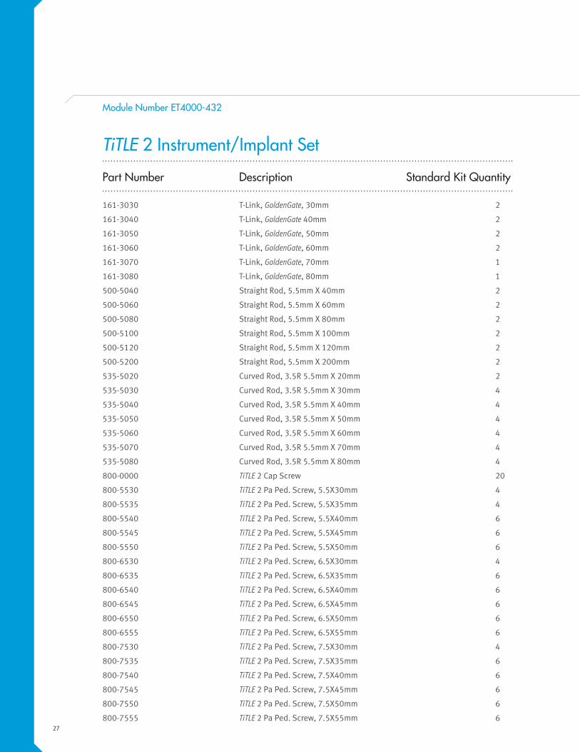
Part Number Description Standard Kit Quantity
161-3030 T-Link, GoldenGate, 30mm 2
161-3040 T-Link, GoldenGate 40mm 2
161-3050 T-Link, GoldenGate, 50mm 2
161-3060 T-Link, GoldenGate, 60mm 2
161-3070 T-Link, GoldenGate, 70mm 1
161-3080 T-Link, GoldenGate, 80mm 1
500-5040 Straight Rod, 5.5mm X 40mm 2
500-5060 Straight Rod, 5.5mm X 60mm 2
500-5080 Straight Rod, 5.5mm X 80mm 2
500-5100 Straight Rod, 5.5mm X 100mm 2
500-5120 Straight Rod, 5.5mm X 120mm 2
500-5200 Straight Rod, 5.5mm X 200mm 2
535-5020 Curved Rod, 3.5R 5.5mm X 20mm 2
535-5030 Curved Rod, 3.5R 5.5mm X 30mm 4
535-5040 Curved Rod, 3.5R 5.5mm X 40mm 4
535-5050 Curved Rod, 3.5R 5.5mm X 50mm 4
535-5060 Curved Rod, 3.5R 5.5mm X 60mm 4
535-5070 Curved Rod, 3.5R 5.5mm X 70mm 4
535-5080 Curved Rod, 3.5R 5.5mm X 80mm 4
800-0000 TiTLE 2 Cap Screw 20
800-5530 TiTLE 2 Pa Ped. Screw, 5.5X30mm 4
800-5535 TiTLE 2 Pa Ped. Screw, 5.5X35mm 4
800-5540 TiTLE 2 Pa Ped. Screw, 5.5X40mm 6
800-5545 TiTLE 2 Pa Ped. Screw, 5.5X45mm 6
800-5550 TiTLE 2 Pa Ped. Screw, 5.5X50mm 6
800-6530 TiTLE 2 Pa Ped. Screw, 6.5X30mm 4
800-6535 TiTLE 2 Pa Ped. Screw, 6.5X35mm 6
800-6540 TiTLE 2 Pa Ped. Screw, 6.5X40mm 6
800-6545 TiTLE 2 Pa Ped. Screw, 6.5X45mm 6
800-6550 TiTLE 2 Pa Ped. Screw, 6.5X50mm 6
800-6555 TiTLE 2 Pa Ped. Screw, 6.5X55mm 6
800-7530 TiTLE 2 Pa Ped. Screw, 7.5X30mm 4
800-7535 TiTLE 2 Pa Ped. Screw, 7.5X35mm 6
800-7540 TiTLE 2 Pa Ped. Screw, 7.5X40mm 6
800-7545 TiTLE 2 Pa Ped. Screw, 7.5X45mm 6
800-7550 TiTLE 2 Pa Ped. Screw, 7.5X50mm 6
800-7555 TiTLE 2 Pa Ped. Screw, 7.5X55mm 6
TiTLE 2 Instrument/Implant Set
Module Number ET4000-432
Total Page Count is 36
28
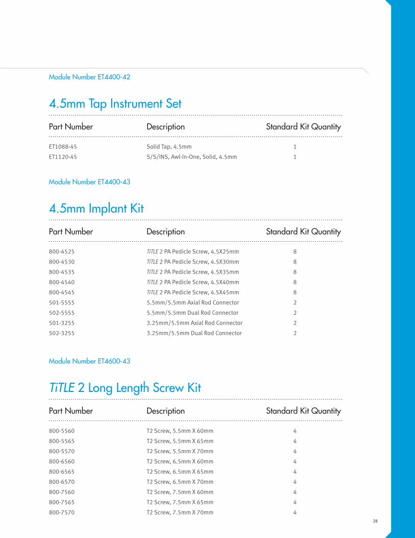
Part Number Description Standard Kit Quantity
ET1088-45 Solid Tap, 4.5mm 1
ET1120-45 S/S/INS, Awl-In-One, Solid, 4.5mm 1
4.5mm Tap Instrument Set
Module Number ET4400-42
Part Number Description Standard Kit Quantity
800-4525 TiTLE 2 PA Pedicle Screw, 4.5X25mm 8
800-4530 TiTLE 2 PA Pedicle Screw, 4.5X30mm 8
800-4535 TiTLE 2 PA Pedicle Screw, 4.5X35mm 8
800-4540 TiTLE 2 PA Pedicle Screw, 4.5X40mm 8
800-4545 TiTLE 2 PA Pedicle Screw, 4.5X45mm 8
501-5555 5.5mm/5.5mm Axial Rod Connector 2
502-5555 5.5mm/5.5mm Dual Rod Connector 2
501-3255 3.25mm/5.5mm Axial Rod Connector 2
502-3255 3.25mm/5.5mm Dual Rod Connector 2
4.5mm Implant Kit
Module Number ET4400-43
Part Number Description Standard Kit Quantity
800-5560 T2 Screw, 5.5mm X 60mm 4
800-5565 T2 Screw, 5.5mm X 65mm 4
800-5570 T2 Screw, 5.5mm X 70mm 4
800-6560 T2 Screw, 6.5mm X 60mm 4
800-6565 T2 Screw, 6.5mm X 65mm 4
800-6570 T2 Screw, 6.5mm X 70mm 4
800-7560 T2 Screw, 7.5mm X 60mm 4
800-7565 T2 Screw, 7.5mm X 65mm 4
800-7570 T2 Screw, 7.5mm X 70mm 4
TiTLE 2 Long Length Screw Kit
Module Number ET4600-43
Total Page Count is 36

29
Warnings and Precautions
Warnings
• The FDA has placed labeling limitations on this device.
• The safety and effectiveness of pedicle screw spinal systems have been established only for
spinal conditions with significant mechanical instability or deformity requiring fusion with
instrumentation. These conditions are significant mechanical instability or deformity of the
thoracic, lumbar, and sacral spine secondary to degenerative spondylolisthesis with objective
evidence of neurological impairment, fracture, dislocation, scoliosis, hypnosis, spinal tumor, and
failed previous fusion (pseudoarthrosis). The safety and effectiveness of these devices for any
other condition is unknown.
• When used as a Pedicle Screw System, this system is intended for Grade 3 or 4 spondylolisthesis
at the fifth lumbar/first sacral joint.
• The benefit of spinal fusions utilizing any pedicle screw fixation has not been adequately
established in patients with stable spines.
• Potential risks identified with the use of this device system, which may require additional
surgery, include device component fracture, loss of fixation, non-union, fracture of the vertebrae,
neurological injury, and vascular or visceral injury.
Total Page Count is 36

30
Precautions
• The implantation of Pedicle Screw System should be performed only by experienced spinal
surgeons with specific training in the use of pedicle screw spinal systems because this is a
technically demanding procedure presenting a risk of serious injury to the patient.
• This device system is not intended to be the sole means of support. Its use without bone graft or
in cases that develop into a non-union will not be successful. No spinal implant can withstand the
loads of the body without maturation of a solid fusion mass, and in this case, bending loosening
or fracture of the implant will eventually occur.
• Mixing of dissimilar metals can accelerate the corrosion process. Stainless Steel and Titanium
components must NOT be used together in building a construct.
• No components of the TiTLE 2 Poly Axial Spinal System should be used with components from any
other system or manufacturer, unless otherwise noted in the INDICATIONS section.
• The Delivery Instrumentation should be used to implant and connect the devices. The use of any
other drivers, taps, or other instrumentation may compromise the integrity of the construct.
• As with all orthopedic implants, none of the TiTLE 2 Poly Axial Spinal System implants should ever
be reused under any circumstances.
• Instruments designated for single use must not be reused and must be properly disposed of.
• All implants and some instruments are intended for single use only; refer to the product label to
determine if the instrument is intended for single use only. Single use devices should not be re-
used. Possible risks associated with re-use of single use devices include:
o Mechanical malfunction
o Transmission of infectious agents
• Using bent or damaged Guidewires can adversely affect Cannulated Pedicle Screw placement.
• Torque limiting instrument adjustment screws or caps with set screws should not be manipulated
during the cleaning process. Manipulation or disassembly of the instrument will affect the
calibration of the instrument and it will require re-calibration prior to use.
• Based on the fatigue testing results, the physician/surgeon should consider the levels of
implantation, patient weight, patient activity level, and other patient conditions, etc. which may
impact the performance of the system.
- The proper selection and compliance of the patient will greatly affect the results. Patients who
smoke have been shown to have an increased incidence of non-union. These patients should
be advised of this fact and warned of the consequences. Other poor candidates for spine fusion
include obese, malnourished, poor muscle or bone quality, and nerve paralysis patients.
Total Page Count is 36

31
Total Page Count is 36

32
Total Page Count is 36

7375 Bush Lake RoadEdina, MN 55439800.655.2614
5301 Riata Park Court, Building FAustin, Texas 78727512.918.2700
zimmerspine.com
L1419 Rev. F (851S-1040-00)©2010 Zimmer Spine, Inc.
Solutions by the people of Zimmer Spine.
You are devoted to helping your patients reduce their pain and improve their lives.
And the people of Zimmer Spine are devoted to you. We are dedicated to supporting
you with best-in-class tools, instruments and implants. We are driven by the opportunity
to share our unrivaled education and training. We are committed partners who will
do everything in our power to assist you in your quest to provide the absolute best in
spinal care. And we can be counted on always to act with integrity as ethical partners
who are worthy of your trust. We are the people of Zimmer Spine.
This documentation is intended exclusively for physicians and is not intended for laypersons. Information on the productsand procedures contained in this document is of a general nature and does not represent and does not constitute medicaladvice or recommendations. Because this information does not purport to constitute any diagnostic or therapeutic statementwith regard to any individual medical case, each patient must be examined and advised individually, and this documentdoes not replace the need for such examination and/or advice in whole or in part. Please refer to the package inserts forimportant product information, including, but not limited to, contraindications, warnings, precautions, and adverse effects.
Total Page Count is 36


![The Nervous System. Divisions of the Nervous System Central Nervous System [CNS] = Spinal Cord Brain Peripheral Nervous System [PNS]= Spinal Nerves](https://img.pdfslide.net/doc/110x75/56649d6c5503460f94a4c71d/the-nervous-system-divisions-of-the-nervous-system-central-nervous-system.jpg)